EP2549162A1 - Elektronisches expansionsventil - Google Patents
Elektronisches expansionsventil Download PDFInfo
- Publication number
- EP2549162A1 EP2549162A1 EP11756177A EP11756177A EP2549162A1 EP 2549162 A1 EP2549162 A1 EP 2549162A1 EP 11756177 A EP11756177 A EP 11756177A EP 11756177 A EP11756177 A EP 11756177A EP 2549162 A1 EP2549162 A1 EP 2549162A1
- Authority
- EP
- European Patent Office
- Prior art keywords
- refrigerant
- electronic expansion
- expansion valve
- valve body
- valve
- Prior art date
- Legal status (The legal status is an assumption and is not a legal conclusion. Google has not performed a legal analysis and makes no representation as to the accuracy of the status listed.)
- Withdrawn
Links
Images




Classifications
-
- F—MECHANICAL ENGINEERING; LIGHTING; HEATING; WEAPONS; BLASTING
- F25—REFRIGERATION OR COOLING; COMBINED HEATING AND REFRIGERATION SYSTEMS; HEAT PUMP SYSTEMS; MANUFACTURE OR STORAGE OF ICE; LIQUEFACTION SOLIDIFICATION OF GASES
- F25B—REFRIGERATION MACHINES, PLANTS OR SYSTEMS; COMBINED HEATING AND REFRIGERATION SYSTEMS; HEAT PUMP SYSTEMS
- F25B41/00—Fluid-circulation arrangements
- F25B41/30—Expansion means; Dispositions thereof
- F25B41/31—Expansion valves
- F25B41/34—Expansion valves with the valve member being actuated by electric means, e.g. by piezoelectric actuators
-
- F—MECHANICAL ENGINEERING; LIGHTING; HEATING; WEAPONS; BLASTING
- F25—REFRIGERATION OR COOLING; COMBINED HEATING AND REFRIGERATION SYSTEMS; HEAT PUMP SYSTEMS; MANUFACTURE OR STORAGE OF ICE; LIQUEFACTION SOLIDIFICATION OF GASES
- F25B—REFRIGERATION MACHINES, PLANTS OR SYSTEMS; COMBINED HEATING AND REFRIGERATION SYSTEMS; HEAT PUMP SYSTEMS
- F25B41/00—Fluid-circulation arrangements
- F25B41/30—Expansion means; Dispositions thereof
- F25B41/31—Expansion valves
- F25B41/34—Expansion valves with the valve member being actuated by electric means, e.g. by piezoelectric actuators
- F25B41/345—Expansion valves with the valve member being actuated by electric means, e.g. by piezoelectric actuators by solenoids
-
- Y—GENERAL TAGGING OF NEW TECHNOLOGICAL DEVELOPMENTS; GENERAL TAGGING OF CROSS-SECTIONAL TECHNOLOGIES SPANNING OVER SEVERAL SECTIONS OF THE IPC; TECHNICAL SUBJECTS COVERED BY FORMER USPC CROSS-REFERENCE ART COLLECTIONS [XRACs] AND DIGESTS
- Y02—TECHNOLOGIES OR APPLICATIONS FOR MITIGATION OR ADAPTATION AGAINST CLIMATE CHANGE
- Y02B—CLIMATE CHANGE MITIGATION TECHNOLOGIES RELATED TO BUILDINGS, e.g. HOUSING, HOUSE APPLIANCES OR RELATED END-USER APPLICATIONS
- Y02B30/00—Energy efficient heating, ventilation or air conditioning [HVAC]
- Y02B30/70—Efficient control or regulation technologies, e.g. for control of refrigerant flow, motor or heating
Definitions
- the present invention relates to an electronic expansion valve annexed to a refrigerant cycle of an automatic vending machine or the like, and in particular, relates to an electronic expansion valve that controls a refrigerant by pulse energizing a solenoid, and opening and closing a valve body with electromagnetic force.
- an electronic expansion valve there is known an electronic expansion valve with high controllability that regulates the extent of expansion of a refrigerant by changing the extent to which an expansion path is opened using a stepping motor (for example, refer to Patent Document 1), but as a stepping motor is used, the price is high.
- a low priced pulse drive type expansion valve that regulates the extent of expansion of a refrigerant by opening and closing an electromagnetic valve (for example, refer to Patent Document 2).
- pulse drive type expansion valve a refrigerant flow rate control device
- An operating configuration of the pulse drive type expansion valve is such that a valve body is opened by a solenoid, and the valve body is closed by a coil spring.
- the invention having been contrived bearing in mind the heretofore described situation, has an object of providing a low cost refrigerant cycle electronic expansion valve that solves the heretofore described problem, and operates stably over a long period.
- an electronic expansion valve is characterized by including a small hole that expands a refrigerant, a valve body that opens and closes the small hole, an elastic member that biases the valve body so as to close the small hole, and a solenoid that suctions the valve body so as to open the small hole, the electronic expansion valve expanding the refrigerant by opening and closing the valve body, wherein the elastic member is a disc spring that has plural slits formed in a spiral form in a disc-like board and disposed at mutually equal pitches.
- An electronic expansion valve according to claim 2 of the invention is characterized in that, in the electronic expansion valve according to claim 1, the valve body is opened and closed in a certain cycle.
- the electronic expansion valve of claim 1 has the elastic member that biases the valve body so as to close the small hole that expands the refrigerant and the solenoid that suctions the valve body in such a way as to open the small hole, and expands the refrigerant by opening and closing the valve body, wherein the rigidity of the valve body in the radial direction is increased, and the valve body optimally driven in the axial direction, by the elastic member being a disc spring that has plural slits formed in a spiral form in a disc-like board and disposed at mutually equal pitches, meaning that there is no need for a guide that regulates the axial direction, as a result of which the occurrence of sludge due to sliding is suppressed. Because of this, it is possible to provide a low cost refrigerant cycle electronic expansion valve that operates stably over a long period.
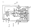
- Fig. 1 is a diagram of a heat pump operation refrigerant circuit of an automatic vending machine having three product storage chambers, one chamber dedicated to cooling and two chambers used for cooling and heating. Dotted line enclosures in the diagram schematically indicate a product storage chamber 40a dedicated to cooling and product storage amounts 40b and 40c used for cooling and heating.
- a heat pump automatic vending machine cooling/heating unit 10 is configured by a compressor 11, a condenser 12, electronic expansion valves 50a, 50b, and 50c, an accumulator 18, and an external auxiliary heat exchanger 19 being installed inside a machine chamber provided in a lower portion of the automatic vending machine, an evaporator 15a and internal heat exchangers 15b and 15c being installed inside the product storage chambers 40a, 40b, and 40c provided in an upper portion of the automatic vending machine, and each instrument being connected by refrigerant piping.
- the cooling/heating unit 10 circulates cooled or heated air inside the chambers using the evaporator 15a and internal heat exchangers 15b and 15c in accordance with a cooling and heating operation setting mode, thus cooling or heating products in product storage racks installed in the chambers.
- the cooling and heating compressor 11 is for compressing a refrigerant and circulating it in the circuit, is used with an evaporating temperature of approximately -10°C and a condensing temperature of approximately 40°C at a time of a cooling-only operation, and is used with an evaporating temperature of approximately -10°C and a condensing temperature of approximately 70°C at a time of a cooling and heating operation (a heat pump operation).
- a heat pump operation For example, when an R134a is used as the refrigerant, an operation is carried out at a low pressure of approximately 0.2MPa, and a high pressure of approximately 1MPa at a time of a cooling-only operation and approximately 2MPa at a time of a cooling and heating operation.
- the condenser 12 is a finned tube type heat exchanger, a fan 12f is installed in a rear portion thereof, and it is for ejecting excessive heat of condensation at a time of a cooling operation.
- a flow divider 14 is for distributing the refrigerant to the evaporator 15a and internal heat exchangers 15b and 15c.
- the evaporator 15a is for cooling the product storage chamber 40a, while the internal heat exchangers 15b and 15c are for cooling or heating the product storage chambers 40b and 40c. Also, the evaporator 15a and internal heat exchangers 15b and 15c are installed one in a lower portion of each product storage chamber, a fan 15f is installed to the rear thereof, and a duct is installed to the rear of the fan 15f.
- the cooling and heating inside the product storage chambers is carried out by air cooled or heated by the evaporator 15a and internal heat exchangers 15b and 15c being blown onto the products inside the product storage chambers, and circulated by and recovered from the ducts.
- a collector 17 is for collecting the refrigerant evaporated from the evaporator 15a and internal heat exchangers 15b and 15c, and returning it to the compressor 11.
- the accumulator 18 is an airtight container for taking in the evaporated refrigerant from the collector 17, dividing it into gas and liquid, accumulating the liquid refrigerant, and returning the gas refrigerant to the compressor 11. Also, the accumulator 18 is also a container for accumulating refrigerant surplus to the circuit refrigerant circulation.
- the external auxiliary heat exchanger 19 is a finned tube type heat exchanger, and is for ejecting excessive heat of condensation at a time of a heating operation.
- a condenser electromagnetic valve 21 is a three-way electromagnetic valve for switching the flow of refrigerant expelled from the compressor 11 to the condenser 12 or the internal heat exchangers 15b and 15c.
- Heater electromagnetic valves 21b and 21c open and close paths of the compressed refrigerant flowing from the compressor 11 to the internal heat exchangers 15b and 15c.
- Cooler outlet electromagnetic valves 23b and 23c open and close paths of the evaporated refrigerant between the internal heat exchangers 15b and 15c and the compressor 11.
- Check valves 24 and 24 are connected one each between the external auxiliary heat exchanger 19 and the internal heat exchangers 15b and 15c, and are for preventing high pressure refrigerant from flowing into the internal heat exchangers 15b and 15c at a time of a cooling or heating operation.
- Check valves 24b and 24c are connected one each between the electronic expansion valves 50b and 50c and heater electromagnetic valves 21b and 21c, and are for preventing high pressure refrigerant from the heater electromagnetic valves 21b and 21c from flowing into the electronic expansion valves 50b and 50c.
- a check valve 25 is connected between an outlet portion of the condenser 12 and an inlet portion of the flow divider 14, and is for preventing high pressure refrigerant from flowing into the condenser 12 at a time of a cooling or heating operation.
- Evaporator temperature sensors 26a, 26b, and 26c are installed in the evaporator 15a and internal heat exchangers 15b and 15c, and are for detecting the evaporating temperature of the evaporator 15a and internal heat exchangers 15b and 15c.
- Internal temperature sensors 41a, 41b, and 41c are installed in the product storage chambers 40a, 40b, and 40c, and are for detecting the internal temperature of the product storage chambers 40a, 40b, and 40c.
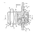
- the electronic expansion valves 50 reduce the pressure of, and adiabatically expand, refrigerant passing through at a time of a cooling operation, and also act as electromagnetic valves that open and close paths of the expanded refrigerant flowing to the evaporator 15a and internal heat exchangers 15b and 15c. A description will be given while referring to Figs. 2 and 3 .
- the electronic expansion valve 50 is configured to have a main body upper portion 51, a main body lower portion 52, a main body side portion 53, a valve seat 54, an armature 55, a spacer 56, pins 57, a solenoid 61, fixing pieces 63a and 63b, nuts 64, and a disc spring (elastic member) 70.
- the main body upper portion 51 is a ferromagnetic cylindrical member, and has an inflow portion 51a, into which a refrigerant inlet pipe 58 is inserted, in an upper portion, a suction portion 51b that suctions the armature 55 in a lower portion, a vertical hole 51c linking to the refrigerant inlet pipe 58 on a central axis, and a horizontal hole 51d, linking to the vertical hole 51c, that extends radially, leading to a main body internal portion 60 of the electronic expansion valve 50. Refrigerant flowing in from the refrigerant inlet pipe 58 flows out in a radial direction to the main body internal portion 60 of the electronic expansion valve 50 via the vertical hole 51c and horizontal hole 51d.
- the main body lower portion 52 is a ferromagnetic cylindrical member, and has an outflow portion 52a, into which a refrigerant outlet pipe 59 is inserted, in a lower portion, an internal space 52b, inside which the valve seat 54 and armature 55 are installed, in an upper portion, and a hole 52c linking an orifice (small hole) 54a formed in the valve seat 54 and the refrigerant outlet pipe 59 on a central axis.
- the main body side portion 53 is a non-magnetic cylindrical member, and engages with the main body upper portion 51 and main body lower portion 52 to form the main body internal portion 60.
- the valve seat 54 being a non-magnetic cylindrical member, is fixed to the main body lower portion 52, the upper surface is flat, and an orifice (small hole) 54a is bored on a central axis.
- the armature 55 is a ferromagnetic cylindrical member with a three stage structure whose central diameter is larger, and has an adsorption portion 55a of which an upper end surface of an upper portion is flat, a side portion 55b of which a central portion maintains a sufficient gap with the internal space 52b, and a valve body 55c of which a lower end surface of a lower portion is flat and closely attached to an upper portion of the valve seat 54, closing the orifice 54a.
- the armature 55, an upper end surface of the side portion 55b and the disc spring 70 being fixed by caulking, is attached providing a gap 60a between the adsorption portion 55a and suction portion 51b, and attached in such a way as to be biased toward the valve seat 54 by the disc spring 70.
- a groove 55d forming a refrigerant path is formed in such a way as to oppose the axial direction in a peripheral surface of the side portion 55b of the armature 55, as shown in Fig. 3 .
- the spacer 56 is a non-magnetic cylindrical member, and is for regulating the distance between the main body upper portion 51 and main body lower portion 52.
- the four pins 57 are fixing members for fixing the disc spring 70 in four peripheral places.
- the refrigerant inlet pipe 58 is piping for allowing condensed refrigerant to flow into the electronic expansion valve 50, while the refrigerant outlet pipe 59 is piping for allowing refrigerant expanded by the electronic expansion valve 50 to flow out of the electronic expansion valve 50.
- the solenoid 61 is for releasing the valve body 55c from the orifice 54a by suctioning the armature 55, and is configured of an iron core 61a and a coil 61b.
- the solenoid 61 has screw portions in an upper portion, and is fixed to the nuts 64 via the fixing pieces 63a and 63b.
- the fixing pieces 63a and 63b are ferromagnetic plate members, with both ends of a flat surface formed semi-circularly, and are for fixing the solenoid 61, and for fixing both the main body upper portion 51 and main body lower portion 52 with screws.
- a magnetic flux emitted from the coil 61b flows along a magnetic circuit from the iron core 61a, fixing piece 63a, main body upper portion 51, gap 60a, armature 55, main body lower portion 52, and fixing piece 63b, returning to the iron core 61a.
- the disc spring 70 is configured to have a main body plate (a disc-like board) 71 configured of a disc-like thin plate member, fixing holes 72 for fixing the disc spring 70 to the main body lower portion 52, slits 73 formed in a spiral form at mutually equal pitches in the main body plate 71, and a central hole 74 for engaging with the armature 55 in the center.
- a main body plate a disc-like board
- slits 73 formed in a spiral form are formed at equal pitches in four places in the main body plate 71, straightness in the axial direction is high, and rigidity in the radial direction is high. For this reason, unlike with a coil spring, there is no need for a guide that regulates a drive in the axial direction when the armature 55 is suctioned by the suction portion 51b.
- condensed refrigerant flowing in from the refrigerant inlet pipe 58 flows into the gap 60b via the vertical hole 51c, horizontal hole 51d, and main body internal portion 60 of the main body upper portion 51, the slits 73 of the disc spring 70, and the groove 55d of the armature 55, as shown by arrows in the drawing, is expanded by the orifice 54a, becomes two phases of refrigerant, gas and liquid, and flows out from the refrigerant outlet pipe 59. Also, by repeating the energizing of the solenoid 61 in a certain cycle, it is possible to control a refrigerant flow rate and a degree of superheat of a refrigerant cycle.
- the refrigerant circuit has a cooling-only circuit 10A that carries out only a cooling inside a chamber, and a cooling and heating circuit (heat pump operation circuit) 10B that simultaneously carries out a cooling and heating inside a chamber.
- a cooling-only circuit 10A that carries out only a cooling inside a chamber
- a cooling and heating circuit (heat pump operation circuit) 10B that simultaneously carries out a cooling and heating inside a chamber.
- the cooling-only circuit 10A is a circuit that is connected from the compressor 11 via the condenser electromagnetic valve 21, condenser 12, and check valve 25 to the flow divider 14, with one branch connecting to the collector 17 via the electromagnetic expansion valve 50a and evaporator 15a from the flow divider 14, and other branches connecting to the collector 17 via the electromagnetic expansion valves 50b and 50c, check valves 24b and 24c, internal heat exchangers 15b and 15c, and cooler outlet electromagnetic valves 23b and 23c from the flow divider 14, and returns to the compressor 11 from the collector 17 via the accumulator 18.
- the cooling and heating circuit 10B in addition to the cooling-only circuit 10A, there are provided pipelines connected from one outlet of the condenser electromagnetic valve 21, via the parallel connected heater electromagnetic valves 21b and 21c, to each of connection points 121b and 121c between the check valves 24b and 24c and the inlet side of the internal heat exchangers 15b and 15c, and pipelines that, after passing from the outlet side (the right side in the drawing) of the internal heat exchangers 15b and 15c through one each of the check valves 24 and 24 and joining, are connected to the flow divider 14 via the external auxiliary heat exchanger 19.
- the cooling and heating circuit 10B is a circuit that is connected from the compressor 11 via the condenser electromagnetic valve 21 and heater electromagnetic valves 21b and 21c to the internal heat exchangers 15b and 15c, connected from the internal heat exchangers 15b and 15c via the check valves 24 and 24 and external auxiliary heat exchanger 19 to the flow divider 14, connected from the flow divider 14 via the electronic expansion valve 50a to the evaporator 15a, and returns to the compressor 11 via the collector 17 and accumulator 18.
- a control device 90 carries out a control of a cooling or heating of the product storage chambers 40a, 40b, and 40c in accordance with a cooling and heating operation mode setting.
- the control device 90 has an internal CPU and memory, and carries out a control of a refrigerant circuit compressor operation, electromagnetic valve opening and closing, electronic expansion valve, and the like, in accordance with an operation mode setting of a cooling and heating mode setting switch 91, the temperature of each chamber, and the evaporating temperature.
- the control device 90 When controlling the temperature inside the chambers, the control device 90 maintains the temperature inside the chambers at an appropriate level by controlling the compressor 11, the condenser electromagnetic valve 21, the electronic expansion valves 50a, 50b, and 50c, the cooler outlet electromagnetic valves 23b and 23c, the heater electromagnetic valves 21b and 21c, and the like, in accordance with the temperatures detected by the internal temperature sensors 41a, 41b, and 41c, and carrying out a thermal cycling operation that on-off controls the inside of the chambers within a certain temperature range.
- the control device 90 controls the refrigerant flow rate and evaporating temperature by pulse drive controlling the electronic expansion valves 50a, 50b, and 50c in accordance with the temperatures detected by the evaporator temperature sensors 26a, 26b, and 26c. Specifically, the control device 90 sends a pulse signal every time a certain cycle time (for example, ten seconds) elapses, with the duty ratio (the ratio of the on time with respect to the cycle time) within a range of 30 to 100%, and controls the evaporating temperatures of the evaporator 15a and internal heat exchangers 15c and 15b to predetermined temperatures by opening and closing the valve body 55c in the electronic expansion valves 50a, 50b, and 50c.
- a certain cycle time for example, ten seconds
- the control device 90 when setting to an operation mode that cools all the product storage chambers with an operation of the cooling and heating mode setting switch 91, the control device 90 opens the cooler outlet electromagnetic valves 23b and 23c, closes the heater electromagnetic valves 21b and 21c, and carries out a switching of the condenser electromagnetic valve 21 paths in such a way that the refrigerant flows to the condenser 12 side. At this time, the refrigerant flows as shown by the heavy lines of Fig.
- a high temperature refrigerant compressed by the compressor 11 passes through the condenser electromagnetic valve 21 and is condensed by the condenser 12, becoming a liquid, the flow is divided into three in the flow divider 14, the liquid is expanded in the electronic expansion valves 50a, 50b, and 50c, becomes a low temperature gas-liquid two phase flow, and flows into the evaporator 15a and internal heat exchangers 15b and 15c.
- the inflowing refrigerant evaporates in the evaporator 15a and internal heat exchangers 15b and 15c, cooling the product storage chambers 40a, 40b, and 40c, the evaporated refrigerant is collected by the collector 17 and divided into gas and liquid using the accumulator 18, and the gas phase returns to the compressor 11.
- the cooling is such that the temperature in the chambers is controlled to an appropriate temperature by the control device 90 with a thermal cycling operation using the internal temperature sensors 41a, 41b, and 41c. Also, the control device 90 sends a pulse signal, changing the duty ratio, to the electronic expansion valves 50a, 50b, and 50c so that the evaporating temperature of the evaporator 15a and internal heat exchangers 15b and 15c becomes a predetermined temperature. That is, when the evaporating temperature is higher than the predetermined temperature, the control device 90 sends a pulse signal with a high duty ratio.
- the heretofore described control is such that the operation is continued until the temperature in the chambers reaches the appropriate level and, when one product storage chamber reaches the appropriate temperature, the power to the electronic expansion valve 50 corresponding to the product storage chamber is shut off, and the valve body 55c is closed. Then, the heretofore described control is continued until all the product storage chambers reach the appropriate temperature.
- the control device 90 opens the heater electromagnetic valves 21b and 21c, closes the electronic expansion valves 50b and 50c and cooler outlet electromagnetic valves 23b and 23c, and carries out a switching of the condenser electromagnetic valve 21 paths in such a way that the refrigerant flows to the heater electromagnetic valves 21b and 21c side.
- a high temperature refrigerant compressed by the compressor 11 flows into the internal heat exchangers 15b and 15c via the condenser electromagnetic valve 21, heater electromagnetic valves 21b and 21c, and contact points 121b and 121c, as shown by the heavy lines of Fig. 7 .
- the refrigerant flowing into the internal heat exchangers 15b and 15c condenses, heats the product storage chambers 40b and 40c, is collected by the check valves 24 and 24, further condenses in the external auxiliary heat exchanger 19, and flows into the electronic expansion valve 50a via the flow divider 14.
- the refrigerant flowing into the electronic expansion valve 50a expands, becomes a low temperature, low pressure gas-liquid two phase flow, and flows into the evaporator 15a.
- the refrigerant flowing into the evaporator 15a evaporates, cooling the product storage chamber 40a, and returns to the compressor 11 via the collector 17 and accumulator 18.
- This heat pump operation is also such that the electronic expansion valve 50a is controlled so that the evaporating temperature of the evaporator 15a becomes a predetermined temperature, as heretofore described, and the inside of the chamber is maintained at an appropriate temperature with a thermal cycling operation.
- the electronic expansion valves 50a, 50b and 50c have the disc spring 70 that biases the valve body 55c so as to close the orifice 54a that expands the refrigerant and the solenoid 61 that suctions the valve body 55c in such a way as to open the orifice 54a, and expand the refrigerant by opening and closing the valve body 55c, wherein the rigidity of the valve body 55c in the radial direction is increased, and the valve body 55c optimally driven in the axial direction, by the plural slits 73 formed in a spiral form being provided at mutually equal pitches on the perimeter in the disc spring 70, meaning that there is no need for a guide that regulates the axial direction, as a result of which the occurrence of sludge due to sliding is suppressed. Because of this, it is possible to provide a low cost refrigerant cycle electronic expansion valve that operates stably over a long period.
- the electronic expansion valve according to the invention is appropriate for use in an instrument having a refrigerant circuit that cools or heats an automatic vending machine, air conditioner, or the like.
Landscapes
- Engineering & Computer Science (AREA)
- Physics & Mathematics (AREA)
- Mechanical Engineering (AREA)
- Thermal Sciences (AREA)
- General Engineering & Computer Science (AREA)
- Magnetically Actuated Valves (AREA)
- Devices That Are Associated With Refrigeration Equipment (AREA)
Applications Claiming Priority (2)
| Application Number | Priority Date | Filing Date | Title |
|---|---|---|---|
| JP2010062406A JP2011196428A (ja) | 2010-03-18 | 2010-03-18 | 電子膨張弁 |
| PCT/JP2011/055676 WO2011114991A1 (ja) | 2010-03-18 | 2011-03-10 | 電子膨張弁 |
Publications (2)
| Publication Number | Publication Date |
|---|---|
| EP2549162A1 true EP2549162A1 (de) | 2013-01-23 |
| EP2549162A4 EP2549162A4 (de) | 2013-07-24 |
Family
ID=44649086
Family Applications (1)
| Application Number | Title | Priority Date | Filing Date |
|---|---|---|---|
| EP11756177.9A Withdrawn EP2549162A4 (de) | 2010-03-18 | 2011-03-10 | Elektronisches expansionsventil |
Country Status (5)
| Country | Link |
|---|---|
| US (1) | US8857788B2 (de) |
| EP (1) | EP2549162A4 (de) |
| JP (1) | JP2011196428A (de) |
| CN (1) | CN102483178B (de) |
| WO (1) | WO2011114991A1 (de) |
Families Citing this family (5)
| Publication number | Priority date | Publication date | Assignee | Title |
|---|---|---|---|---|
| DE202015006366U1 (de) * | 2015-09-07 | 2016-12-08 | Gebr. Kemper Gmbh + Co. Kg Metallwerke | Trink- und Brauchwasserversorgungseinrichtung eines Gebäudes und Regulierventil hierfür |
| WO2017179088A1 (ja) * | 2016-04-11 | 2017-10-19 | 三菱電機株式会社 | 冷凍装置および冷凍装置の制御方法 |
| CN111623126A (zh) * | 2019-02-28 | 2020-09-04 | 浙江盾安禾田金属有限公司 | 电子膨胀阀 |
| CN111412684B (zh) * | 2020-04-20 | 2020-12-15 | 珠海格力电器股份有限公司 | 节流元件失效的控制方法及空调 |
| KR102548358B1 (ko) * | 2020-09-07 | 2023-06-28 | 한온시스템 주식회사 | 베이퍼 인젝션 모듈 및 이를 이용하는 히트펌프 시스템 |
Family Cites Families (26)
| Publication number | Priority date | Publication date | Assignee | Title |
|---|---|---|---|---|
| US3589672A (en) * | 1969-02-18 | 1971-06-29 | Trans Lux Corp | Solenoid controlled valve and armature with adjustable bias |
| JPS51117226U (de) * | 1975-03-19 | 1976-09-22 | ||
| JPS531352A (en) | 1976-06-28 | 1978-01-09 | Hitachi Ltd | Cooling medium flow control means |
| JPS57167972U (de) * | 1981-04-16 | 1982-10-22 | ||
| JPH06147350A (ja) * | 1991-12-03 | 1994-05-27 | Ckd Corp | 差動式比例制御弁 |
| CN2200083Y (zh) * | 1994-04-08 | 1995-06-07 | 西安交通大学 | 电子膨胀阀 |
| US5785297A (en) * | 1996-07-16 | 1998-07-28 | Millipore Corporation | Valve mechanism |
| JP3557837B2 (ja) * | 1997-03-25 | 2004-08-25 | 東海ゴム工業株式会社 | 流体封入式防振装置 |
| JP4042184B2 (ja) * | 1997-08-06 | 2008-02-06 | アイシン精機株式会社 | 電磁弁 |
| JPH1182801A (ja) * | 1997-09-16 | 1999-03-26 | Fuji Koki Corp | 電磁弁 |
| JP3786518B2 (ja) * | 1998-04-23 | 2006-06-14 | 株式会社テージーケー | 電磁弁付膨張弁 |
| JPH11316068A (ja) * | 1998-05-07 | 1999-11-16 | Tgk Co Ltd | 膨張弁 |
| US6343751B1 (en) * | 1999-02-23 | 2002-02-05 | Aisan Kogyo Kabushiki Kaisha | Electromagnetic fuel injection valve |
| US6443183B1 (en) * | 2000-06-07 | 2002-09-03 | Transcend Inc. | Valve and assembly for axially movable members |
| JP2002071045A (ja) * | 2000-08-29 | 2002-03-08 | Saginomiya Seisakusho Inc | 電磁比例弁 |
| JP2003156268A (ja) * | 2001-11-16 | 2003-05-30 | Tgk Co Ltd | 電磁膨張装置およびその制御方法 |
| DE60328064D1 (de) * | 2002-04-12 | 2009-08-06 | Seiko Epson Corp | Ventilanordnung |
| JP4028291B2 (ja) | 2002-05-16 | 2007-12-26 | 株式会社鷺宮製作所 | 電動弁の駆動装置及び冷凍サイクル装置 |
| JP4235515B2 (ja) * | 2003-09-12 | 2009-03-11 | 株式会社テージーケー | 定差圧弁 |
| US7055798B2 (en) * | 2004-02-06 | 2006-06-06 | Kojima Instruments Inc. | Proportional solenoid control valve |
| JP5022120B2 (ja) * | 2007-07-03 | 2012-09-12 | 株式会社不二工機 | 冷暖房システム用の電動弁 |
| ITBS20070120A1 (it) * | 2007-08-08 | 2009-02-09 | Camozzi S P A Societa Uniperso | Elettrovalvola e relativo metodo di montaggio |
| JP2009167924A (ja) * | 2008-01-17 | 2009-07-30 | Nikki Co Ltd | インジェクタ |
| US8430378B2 (en) * | 2008-05-30 | 2013-04-30 | South Bend Controls Holdings Llc | High flow proportional valve |
| CN101691890B (zh) * | 2009-10-13 | 2011-08-31 | 金仁召 | 一种节流阀 |
| EP2400193B1 (de) * | 2010-06-23 | 2019-08-28 | Asco Numatics GmbH | Vorrichtung zur Durchflussregelung eines flüssigen oder gasförmigen Mediums |
-
2010
- 2010-03-18 JP JP2010062406A patent/JP2011196428A/ja active Pending
-
2011
- 2011-03-10 WO PCT/JP2011/055676 patent/WO2011114991A1/ja not_active Ceased
- 2011-03-10 CN CN201180003410.6A patent/CN102483178B/zh active Active
- 2011-03-10 EP EP11756177.9A patent/EP2549162A4/de not_active Withdrawn
- 2011-03-10 US US13/389,748 patent/US8857788B2/en active Active
Also Published As
| Publication number | Publication date |
|---|---|
| CN102483178B (zh) | 2014-08-06 |
| CN102483178A (zh) | 2012-05-30 |
| WO2011114991A1 (ja) | 2011-09-22 |
| JP2011196428A (ja) | 2011-10-06 |
| US20120326064A1 (en) | 2012-12-27 |
| US8857788B2 (en) | 2014-10-14 |
| EP2549162A4 (de) | 2013-07-24 |
Similar Documents
| Publication | Publication Date | Title |
|---|---|---|
| US9612047B2 (en) | Refrigeration cycle apparatus and refrigerant circulation method | |
| CN105579788B (zh) | 喷射器式制冷循环 | |
| CN102032699B (zh) | 冷冻循环装置以及水暖装置 | |
| EP2549162A1 (de) | Elektronisches expansionsventil | |
| CN105593610B (zh) | 热泵系统及热泵式供热水机 | |
| CN105556220A (zh) | 具有热回收模块的制冷回路 | |
| EP2901091B1 (de) | Kühlschrank und verfahren zur steuerung des kühlschranks | |
| KR20130088430A (ko) | 냉장고 | |
| CN113286974B (zh) | 用于器具的快速切换多蒸发器系统 | |
| EP3062041A1 (de) | Kühlvorrichtung | |
| US10739044B2 (en) | Method for installing expansion device in a sealed system | |
| JP6079657B2 (ja) | 冷凍サイクル装置 | |
| JP6001997B2 (ja) | ターボ冷凍機 | |
| JP5146884B2 (ja) | 冷凍サイクル用冷媒加熱補助装置及びその冷媒加熱方法 | |
| JP2007139244A (ja) | 冷凍装置 | |
| JP2015143597A (ja) | 給湯装置 | |
| WO2011114992A1 (ja) | 電子膨張弁 | |
| KR20110117974A (ko) | 히트펌프식 급탕장치 | |
| WO2012114451A1 (ja) | 空気調和装置、空気調和装置の運転制御方法および冷却システム | |
| JP2007139257A (ja) | 冷凍装置 | |
| EP2357431A1 (de) | Kühlsystem mit veränderlicher leistung | |
| JP2005257164A (ja) | 冷却装置 | |
| WO2018034275A1 (ja) | 冷凍サイクル装置 | |
| KR101266107B1 (ko) | 공기조화기 및 그 운전 방법 | |
| JP2012021745A (ja) | 電子膨張弁 |
Legal Events
| Date | Code | Title | Description |
|---|---|---|---|
| PUAI | Public reference made under article 153(3) epc to a published international application that has entered the european phase |
Free format text: ORIGINAL CODE: 0009012 |
|
| 17P | Request for examination filed |
Effective date: 20121018 |
|
| AK | Designated contracting states |
Kind code of ref document: A1 Designated state(s): AL AT BE BG CH CY CZ DE DK EE ES FI FR GB GR HR HU IE IS IT LI LT LU LV MC MK MT NL NO PL PT RO RS SE SI SK SM TR |
|
| RIN1 | Information on inventor provided before grant (corrected) |
Inventor name: TAKANO, YUKIHIRO Inventor name: SANUKI, YASUTAKA Inventor name: SAITOH, SHUSUKE Inventor name: MIGISHIMA, NOBUTOSHI Inventor name: TAKIGUCHI, KOUJI Inventor name: INOSHITA, NAOKI |
|
| DAX | Request for extension of the european patent (deleted) | ||
| A4 | Supplementary search report drawn up and despatched |
Effective date: 20130625 |
|
| RIC1 | Information provided on ipc code assigned before grant |
Ipc: F25B 1/00 20060101ALI20130619BHEP Ipc: F16K 31/06 20060101AFI20130619BHEP |
|
| STAA | Information on the status of an ep patent application or granted ep patent |
Free format text: STATUS: EXAMINATION IS IN PROGRESS |
|
| 17Q | First examination report despatched |
Effective date: 20170516 |
|
| GRAP | Despatch of communication of intention to grant a patent |
Free format text: ORIGINAL CODE: EPIDOSNIGR1 |
|
| STAA | Information on the status of an ep patent application or granted ep patent |
Free format text: STATUS: GRANT OF PATENT IS INTENDED |
|
| INTG | Intention to grant announced |
Effective date: 20190705 |
|
| GRAS | Grant fee paid |
Free format text: ORIGINAL CODE: EPIDOSNIGR3 |
|
| STAA | Information on the status of an ep patent application or granted ep patent |
Free format text: STATUS: THE APPLICATION IS DEEMED TO BE WITHDRAWN |
|
| 18D | Application deemed to be withdrawn |
Effective date: 20191116 |