EP2357431A1 - Kühlsystem mit veränderlicher leistung - Google Patents
Kühlsystem mit veränderlicher leistung Download PDFInfo
- Publication number
- EP2357431A1 EP2357431A1 EP10382016A EP10382016A EP2357431A1 EP 2357431 A1 EP2357431 A1 EP 2357431A1 EP 10382016 A EP10382016 A EP 10382016A EP 10382016 A EP10382016 A EP 10382016A EP 2357431 A1 EP2357431 A1 EP 2357431A1
- Authority
- EP
- European Patent Office
- Prior art keywords
- valve
- compressor
- machine
- per
- pressure
- Prior art date
- Legal status (The legal status is an assumption and is not a legal conclusion. Google has not performed a legal analysis and makes no representation as to the accuracy of the status listed.)
- Withdrawn
Links
Images

Classifications
-
- F—MECHANICAL ENGINEERING; LIGHTING; HEATING; WEAPONS; BLASTING
- F25—REFRIGERATION OR COOLING; COMBINED HEATING AND REFRIGERATION SYSTEMS; HEAT PUMP SYSTEMS; MANUFACTURE OR STORAGE OF ICE; LIQUEFACTION SOLIDIFICATION OF GASES
- F25B—REFRIGERATION MACHINES, PLANTS OR SYSTEMS; COMBINED HEATING AND REFRIGERATION SYSTEMS; HEAT PUMP SYSTEMS
- F25B41/00—Fluid-circulation arrangements
- F25B41/20—Disposition of valves, e.g. of on-off valves or flow control valves
- F25B41/22—Disposition of valves, e.g. of on-off valves or flow control valves between evaporator and compressor
-
- F—MECHANICAL ENGINEERING; LIGHTING; HEATING; WEAPONS; BLASTING
- F25—REFRIGERATION OR COOLING; COMBINED HEATING AND REFRIGERATION SYSTEMS; HEAT PUMP SYSTEMS; MANUFACTURE OR STORAGE OF ICE; LIQUEFACTION SOLIDIFICATION OF GASES
- F25B—REFRIGERATION MACHINES, PLANTS OR SYSTEMS; COMBINED HEATING AND REFRIGERATION SYSTEMS; HEAT PUMP SYSTEMS
- F25B2400/00—General features or devices for refrigeration machines, plants or systems, combined heating and refrigeration systems or heat-pump systems, i.e. not limited to a particular subgroup of F25B
- F25B2400/13—Economisers
-
- F—MECHANICAL ENGINEERING; LIGHTING; HEATING; WEAPONS; BLASTING
- F25—REFRIGERATION OR COOLING; COMBINED HEATING AND REFRIGERATION SYSTEMS; HEAT PUMP SYSTEMS; MANUFACTURE OR STORAGE OF ICE; LIQUEFACTION SOLIDIFICATION OF GASES
- F25B—REFRIGERATION MACHINES, PLANTS OR SYSTEMS; COMBINED HEATING AND REFRIGERATION SYSTEMS; HEAT PUMP SYSTEMS
- F25B2600/00—Control issues
- F25B2600/02—Compressor control
- F25B2600/025—Compressor control by controlling speed
- F25B2600/0251—Compressor control by controlling speed with on-off operation
-
- F—MECHANICAL ENGINEERING; LIGHTING; HEATING; WEAPONS; BLASTING
- F25—REFRIGERATION OR COOLING; COMBINED HEATING AND REFRIGERATION SYSTEMS; HEAT PUMP SYSTEMS; MANUFACTURE OR STORAGE OF ICE; LIQUEFACTION SOLIDIFICATION OF GASES
- F25B—REFRIGERATION MACHINES, PLANTS OR SYSTEMS; COMBINED HEATING AND REFRIGERATION SYSTEMS; HEAT PUMP SYSTEMS
- F25B2600/00—Control issues
- F25B2600/02—Compressor control
- F25B2600/026—Compressor control by controlling unloaders
- F25B2600/0261—Compressor control by controlling unloaders external to the compressor
-
- F—MECHANICAL ENGINEERING; LIGHTING; HEATING; WEAPONS; BLASTING
- F25—REFRIGERATION OR COOLING; COMBINED HEATING AND REFRIGERATION SYSTEMS; HEAT PUMP SYSTEMS; MANUFACTURE OR STORAGE OF ICE; LIQUEFACTION SOLIDIFICATION OF GASES
- F25B—REFRIGERATION MACHINES, PLANTS OR SYSTEMS; COMBINED HEATING AND REFRIGERATION SYSTEMS; HEAT PUMP SYSTEMS
- F25B2600/00—Control issues
- F25B2600/25—Control of valves
- F25B2600/2509—Economiser valves
-
- F—MECHANICAL ENGINEERING; LIGHTING; HEATING; WEAPONS; BLASTING
- F25—REFRIGERATION OR COOLING; COMBINED HEATING AND REFRIGERATION SYSTEMS; HEAT PUMP SYSTEMS; MANUFACTURE OR STORAGE OF ICE; LIQUEFACTION SOLIDIFICATION OF GASES
- F25B—REFRIGERATION MACHINES, PLANTS OR SYSTEMS; COMBINED HEATING AND REFRIGERATION SYSTEMS; HEAT PUMP SYSTEMS
- F25B2700/00—Sensing or detecting of parameters; Sensors therefor
- F25B2700/19—Pressures
- F25B2700/193—Pressures of the compressor
- F25B2700/1933—Suction pressures
-
- F—MECHANICAL ENGINEERING; LIGHTING; HEATING; WEAPONS; BLASTING
- F25—REFRIGERATION OR COOLING; COMBINED HEATING AND REFRIGERATION SYSTEMS; HEAT PUMP SYSTEMS; MANUFACTURE OR STORAGE OF ICE; LIQUEFACTION SOLIDIFICATION OF GASES
- F25B—REFRIGERATION MACHINES, PLANTS OR SYSTEMS; COMBINED HEATING AND REFRIGERATION SYSTEMS; HEAT PUMP SYSTEMS
- F25B2700/00—Sensing or detecting of parameters; Sensors therefor
- F25B2700/21—Temperatures
- F25B2700/2117—Temperatures of an evaporator
Definitions
- the invention relates to a capacity control system to be applied to the design and construction of self-contained refrigeration units and refrigeration plants in the industrial and commercial refrigeration sector.
- refrigerant vapour compression where a refrigerant fluid is compressed by mean of a compressor to a high pressure state, which is then condensed in a condenser at high temperature and driven in liquid phase to the evaporating units.
- a restrictor By mean of a restrictor, the liquid refrigerant is expanded to a low pressure state and evaporated in the evaporator at a lower temperature than the refrigerated medium. Finally the refrigerant vapour is driven back to the compressor.
- the present invention has also its origin in the analysis of an advanced cooling system by combining market standard components, such as pressure control valves and liquid injection valves, for the variation of capacity in a hermetic compressor, and in particular in a reciprocating type compressor.
- the invention refers to a new capacity control system to be applied to the construction of self-contained refrigeration units with variable capacity, said units involving at least one compressor and a condenser, said control system consisting of a new combination of pressure control valves able to adapt the refrigerant flow to the instant load.
- the refrigeration units resulting from this invention are most suitable to be used in small refrigeration installations at both positive and negative temperature, in the commercial and industrial refrigeration sectors, such as centralised installations with multiple evaporators, or industrial applications where it is required an accurate control on the evaporator cooling capacity.
- the key to the invention is the innovative combination of control valves that allows adapting the refrigerant flow to the instant load, while keeping the system within the safety limits, and reasonably reducing the power consumption under partial load.
- the present invention results in better performance in comparison to the existing variable capacity systems based on control valves. It has lower power consumption under partial load than the simple hot gas by-pass system, and keeps the operating pressure and temperature within the safety limits even under low load demand. Moreover, the present invention has the advantage of being a much simpler solution than the existing variable capacity compressor technologies, while achieving a similar performance.
- Fig. 1 is the schematic representation of the preferential embodiment of a refrigeration subsystem involving a combination of valves subject to the present invention, said valves being of the type of pressure-driven control valves.
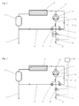
- Fig. 2 is the schematic representation of an alternative refrigeration subsystem, analogue to the one in fig. 1 , wherein one of those pressure-driven valves is replaced by a motor-driven valve as a function of pressure.
- Fig. 3 is the schematic representation of an alternative refrigeration system, analogue to the one in fig. 2 , wherein the electronic control of the motor-driven valve is a function of the temperature of the refrigerated medium.
- Fig. 4 is the schematic representation of an alternative system, analogue to the one in fig. 3 . wherein an economizer is also included.
- the invention relates to system being able to control the capacity of the compressor or compressors in a refrigeration unit, said system consisting of a new combination of temperature and pressure control valves.
- Said combination of valves involves: a restriction valve (1) regulating the refrigerant flow returning to the compressor; a bypass valve (2) between the compressor discharge and the compressor suction line, said valve being adjusted to keep a minimum suction pressure level; and a liquid injection valve (3) between the liquid refrigerant supply line and the compressor suction line, said valve being adjusted to keep a fixed temperature gap between the temperature of the compressor suction line and the dew-point temperature.
- Figure 1 represents a refrigeration subsystem, corresponding to a single-compressor condensing unit or refrigeration plant, based on the principle of the invention.
- This subsystem consists of: a compressor (4), a condenser (5), a liquid receiver (6), a high-pressure refrigerant supply line, (6) and a low pressure refrigerant return line (8).
- This subsystem incorporates the combination of valves as described above.
- the restriction valve (1) regulating the refrigerant flow is installed on the refrigerant return line, said valve keeps the pressure in the return line to a constant value, said valve may consist of a pressure-driven valve, the so-called constant-pressure valve. When restricting the refrigerant return flow, said valve produces a pressure drop in the compressor suction line (10).
- hermetic compressors need at least a certain refrigerant flow rate to be able to cool its motor windings. Thus, a certain minimum suction pressure must be maintained.
- a refrigerant bypass valve (2) is installed on a bypass line (12) between the compressor discharge (11) and the compressor suction line (10).
- Said valve may consist of a pressure-driven control valve, the so-called hot gas bypass valve.
- said control valve opens to introduce hot gas into the compressor suction line (10) to maintain the suction pressure.
- suction gas temperature is also increased.
- suction gas temperature must also be limited to a given value. Such a value is ideally the lowest temperature as possible that ensures the lack of refrigerant in liquid phase. Thus, suction gas temperature should be slightly superheated with respect to its dew-point temperature.
- a liquid injection valve (3) is installed on the compressor suction line (10).
- Said valve may consist of a thermostatic expansion valve, driven by the fluid inside a bulb at the same pressure than the suction line.
- a capillary tube (14) bypassing the pressure control valve (1), said capillary tube being calibrated to admit a small refrigerant flow rate, will produce, under a low load situation, a reduction of pressure in the return line (8), even beyond the pressure set point of the restriction valve (1), said restriction valve being closed under said situation.
- the refrigerant return line (8) is also equipped with a low pressure switch (15), said pressure switch being calibrated to an activation pressure greater than the pressure set point of the bypass valve (2), and said pressure switch turning off the compressor when the pressure in the return line (8) drops below said given value.
- Figure 2 represents an alternative construction of the refrigeration system introduced in figure 1 , wherein the pressure-driven control valve (1), the pressure switch (15) and the capillary tube (14), are replaced by a motor-driven control valve (16), said valve being controlled by an electronic controller as a function of the pressure read by a pressure transducer (17).
- the electronic controller (18) regulates the opening of the motor-driven restriction valve (16) to maintain a constant pressure in the refrigerant return line (8), said pressure being read by the pressure transducer (17).
- the controller orders the complete closing of the motor-driven valve (16), it also turns off the compressor (4).
- Figure 3 represents an alternative construction of a complete refrigeration system, wherein the motor-driven restriction valve (1) is now controlled by an electronic controller (18) as a function of the temperature value read by a temperature probe (20), said probe being placed on the refrigerated medium.
- Such construction in addition involves an evaporator (21) and an expansion valve (22).
- the electronic controller (18) controls the opening of the motor-valve (19) to maintain a constant temperature of the refrigerated medium.
- the controller orders the complete closing of the motor valve (16), it also turns off the compressor (4).
- Figure 4 represents an analogue construction of figure 3 , wherein an economizer (23) is also involved, said economizer being placed between the liquid supply line (7) and the liquid injection line (9).
- an economizer (23) is also involved, said economizer being placed between the liquid supply line (7) and the liquid injection line (9).
- the liquid refrigerant in the supply line (7) is subcooled to provide a greater refrigeration effect.
Landscapes
- Engineering & Computer Science (AREA)
- Physics & Mathematics (AREA)
- Mechanical Engineering (AREA)
- Thermal Sciences (AREA)
- General Engineering & Computer Science (AREA)
- Air Conditioning Control Device (AREA)
Priority Applications (1)
| Application Number | Priority Date | Filing Date | Title |
|---|---|---|---|
| EP10382016A EP2357431A1 (de) | 2010-02-01 | 2010-02-01 | Kühlsystem mit veränderlicher leistung |
Applications Claiming Priority (1)
| Application Number | Priority Date | Filing Date | Title |
|---|---|---|---|
| EP10382016A EP2357431A1 (de) | 2010-02-01 | 2010-02-01 | Kühlsystem mit veränderlicher leistung |
Publications (1)
| Publication Number | Publication Date |
|---|---|
| EP2357431A1 true EP2357431A1 (de) | 2011-08-17 |
Family
ID=42232698
Family Applications (1)
| Application Number | Title | Priority Date | Filing Date |
|---|---|---|---|
| EP10382016A Withdrawn EP2357431A1 (de) | 2010-02-01 | 2010-02-01 | Kühlsystem mit veränderlicher leistung |
Country Status (1)
| Country | Link |
|---|---|
| EP (1) | EP2357431A1 (de) |
Cited By (3)
| Publication number | Priority date | Publication date | Assignee | Title |
|---|---|---|---|---|
| EP2873936A3 (de) * | 2013-11-13 | 2015-08-26 | Mitsubishi Heavy Industries, Ltd. | Wärmepumpensystem |
| WO2017102122A1 (de) * | 2015-12-17 | 2017-06-22 | Man Diesel & Turbo Se | Kälteanlage-umblaseventil und kälteanlage |
| WO2017123602A1 (en) * | 2016-01-12 | 2017-07-20 | Daikin Applied Americas Inc. | Centrifugal compressor with hot gas injection |
Citations (5)
| Publication number | Priority date | Publication date | Assignee | Title |
|---|---|---|---|---|
| EP0981033A2 (de) | 1998-08-20 | 2000-02-23 | Carrier Corporation | Verfahren zum Betreiben einer Kälteanlage in stationärem Betriebszustand |
| US20020021972A1 (en) | 2000-03-16 | 2002-02-21 | Igor Vaisman | Capacity control of refrigeration systems |
| WO2005088212A1 (en) * | 2004-03-01 | 2005-09-22 | Arcelik Anonim Sirketi | A cooling device and control method |
| WO2008079122A1 (en) * | 2006-12-26 | 2008-07-03 | Carrier Corporation | Pulse width modulation with discharge to suction bypass |
| WO2009056561A1 (en) * | 2007-11-02 | 2009-05-07 | L. Oliva Torras, S.A. | Cooling system for an automotive vehicle |
-
2010
- 2010-02-01 EP EP10382016A patent/EP2357431A1/de not_active Withdrawn
Patent Citations (5)
| Publication number | Priority date | Publication date | Assignee | Title |
|---|---|---|---|---|
| EP0981033A2 (de) | 1998-08-20 | 2000-02-23 | Carrier Corporation | Verfahren zum Betreiben einer Kälteanlage in stationärem Betriebszustand |
| US20020021972A1 (en) | 2000-03-16 | 2002-02-21 | Igor Vaisman | Capacity control of refrigeration systems |
| WO2005088212A1 (en) * | 2004-03-01 | 2005-09-22 | Arcelik Anonim Sirketi | A cooling device and control method |
| WO2008079122A1 (en) * | 2006-12-26 | 2008-07-03 | Carrier Corporation | Pulse width modulation with discharge to suction bypass |
| WO2009056561A1 (en) * | 2007-11-02 | 2009-05-07 | L. Oliva Torras, S.A. | Cooling system for an automotive vehicle |
Non-Patent Citations (2)
| Title |
|---|
| WANG ET AL.: "Mechanical Engineering Handbook", 1999, article "Air conditioning and refrigeration", pages: 9.77 |
| WANG: "Handbook of Air conditioning and Refrigeration", 2000, MCGRAW-HILL, pages: 11.24 - 26 |
Cited By (4)
| Publication number | Priority date | Publication date | Assignee | Title |
|---|---|---|---|---|
| EP2873936A3 (de) * | 2013-11-13 | 2015-08-26 | Mitsubishi Heavy Industries, Ltd. | Wärmepumpensystem |
| WO2017102122A1 (de) * | 2015-12-17 | 2017-06-22 | Man Diesel & Turbo Se | Kälteanlage-umblaseventil und kälteanlage |
| CN108603695A (zh) * | 2015-12-17 | 2018-09-28 | 曼柴油机和涡轮机欧洲股份公司 | 制冷系统再循环阀及制冷系统 |
| WO2017123602A1 (en) * | 2016-01-12 | 2017-07-20 | Daikin Applied Americas Inc. | Centrifugal compressor with hot gas injection |
Similar Documents
| Publication | Publication Date | Title |
|---|---|---|
| US9612047B2 (en) | Refrigeration cycle apparatus and refrigerant circulation method | |
| EP1941219B1 (de) | Kältemittelsystem mit pulsbreitenmodulierten komponenten und drehzahlgeregeltem kompressor | |
| CN109073281B (zh) | 用于制冷系统的、具有过冷却器的冷凝器蒸发器系统 | |
| JP4767199B2 (ja) | 空気調和システムの運転制御方法並びに空気調和システム | |
| EP2693133A1 (de) | Wärmequellensystem und verfahren zur zählung einer maschinenanzahl für ein wärmequellensystem | |
| EP2446200B1 (de) | Verfahren mit geringer umweltnutzung für kühlsysteme mit hocheffizienten kondensatoren | |
| EP2837901B1 (de) | Kühlsystem | |
| CN102725596B (zh) | 热泵系统 | |
| JP2011017455A (ja) | ターボ冷凍機 | |
| WO2010047420A1 (ja) | ガスインジエクション冷凍システム | |
| US7475565B2 (en) | Refrigeration system including a side-load sub-cooler | |
| EP3112777B1 (de) | Klimaanlage und betriebsverfahren dafür | |
| EP2357431A1 (de) | Kühlsystem mit veränderlicher leistung | |
| WO2015076331A1 (ja) | 空気調和機 | |
| JP2007225258A (ja) | 冷凍装置 | |
| WO2013140992A1 (ja) | 冷凍サイクル及び冷凍ショーケース | |
| JP5463995B2 (ja) | 多室型空気調和装置 | |
| CN103851817B (zh) | 制冷装置 | |
| CN102997527B (zh) | 气液热交换型冷冻装置 | |
| KR102017405B1 (ko) | 히트 펌프 | |
| JP2014159950A (ja) | 冷凍装置 | |
| US20220252317A1 (en) | A heat pump | |
| CN105783318A (zh) | 冷冻装置 | |
| US20150068037A1 (en) | Thermal System Including an Environmental Test Chamber | |
| EP3078925A1 (de) | Kondensationseinheit mit variabler kapazität |
Legal Events
| Date | Code | Title | Description |
|---|---|---|---|
| PUAI | Public reference made under article 153(3) epc to a published international application that has entered the european phase |
Free format text: ORIGINAL CODE: 0009012 |
|
| AK | Designated contracting states |
Kind code of ref document: A1 Designated state(s): AT BE BG CH CY CZ DE DK EE ES FI FR GB GR HR HU IE IS IT LI LT LU LV MC MK MT NL NO PL PT RO SE SI SK SM TR |
|
| AX | Request for extension of the european patent |
Extension state: AL BA RS |
|
| STAA | Information on the status of an ep patent application or granted ep patent |
Free format text: STATUS: THE APPLICATION IS DEEMED TO BE WITHDRAWN |
|
| 18D | Application deemed to be withdrawn |
Effective date: 20120218 |