EP2547539B1 - Supports de roue pour suspension independant ayant plusieurs bras oscillants - Google Patents
Supports de roue pour suspension independant ayant plusieurs bras oscillants Download PDFInfo
- Publication number
- EP2547539B1 EP2547539B1 EP11706173.9A EP11706173A EP2547539B1 EP 2547539 B1 EP2547539 B1 EP 2547539B1 EP 11706173 A EP11706173 A EP 11706173A EP 2547539 B1 EP2547539 B1 EP 2547539B1
- Authority
- EP
- European Patent Office
- Prior art keywords
- hinge pin
- wheel support
- link connecting
- pin receptacle
- arm
- Prior art date
- Legal status (The legal status is an assumption and is not a legal conclusion. Google has not performed a legal analysis and makes no representation as to the accuracy of the status listed.)
- Active
Links
- 239000000725 suspension Substances 0.000 title claims description 12
- 230000007704 transition Effects 0.000 claims description 2
- 210000000245 forearm Anatomy 0.000 description 9
- 239000000463 material Substances 0.000 description 8
- 229910052782 aluminium Inorganic materials 0.000 description 4
- XAGFODPZIPBFFR-UHFFFAOYSA-N aluminium Chemical compound [Al] XAGFODPZIPBFFR-UHFFFAOYSA-N 0.000 description 4
- 238000010276 construction Methods 0.000 description 4
- 230000009467 reduction Effects 0.000 description 4
- 238000005266 casting Methods 0.000 description 3
- 238000005452 bending Methods 0.000 description 2
- 229920001971 elastomer Polymers 0.000 description 2
- 239000000806 elastomer Substances 0.000 description 2
- 230000007246 mechanism Effects 0.000 description 2
- 238000000034 method Methods 0.000 description 2
- 239000011343 solid material Substances 0.000 description 2
- 229910001018 Cast iron Chemical group 0.000 description 1
- XEEYBQQBJWHFJM-UHFFFAOYSA-N Iron Chemical group [Fe] XEEYBQQBJWHFJM-UHFFFAOYSA-N 0.000 description 1
- 230000009471 action Effects 0.000 description 1
- 230000015572 biosynthetic process Effects 0.000 description 1
- 230000008878 coupling Effects 0.000 description 1
- 238000010168 coupling process Methods 0.000 description 1
- 238000005859 coupling reaction Methods 0.000 description 1
- 238000005520 cutting process Methods 0.000 description 1
- 238000013016 damping Methods 0.000 description 1
- 238000009795 derivation Methods 0.000 description 1
- 238000009826 distribution Methods 0.000 description 1
- 230000000694 effects Effects 0.000 description 1
- 230000008030 elimination Effects 0.000 description 1
- 238000003379 elimination reaction Methods 0.000 description 1
- 239000000446 fuel Substances 0.000 description 1
- 230000000977 initiatory effect Effects 0.000 description 1
- 238000003780 insertion Methods 0.000 description 1
- 230000037431 insertion Effects 0.000 description 1
- 238000005304 joining Methods 0.000 description 1
- 238000004519 manufacturing process Methods 0.000 description 1
- 229910052751 metal Inorganic materials 0.000 description 1
- 239000002184 metal Substances 0.000 description 1
- 230000000149 penetrating effect Effects 0.000 description 1
- 230000036316 preload Effects 0.000 description 1
- 239000003381 stabilizer Substances 0.000 description 1
Images


Classifications
-
- B—PERFORMING OPERATIONS; TRANSPORTING
- B60—VEHICLES IN GENERAL
- B60G—VEHICLE SUSPENSION ARRANGEMENTS
- B60G3/00—Resilient suspensions for a single wheel
- B60G3/18—Resilient suspensions for a single wheel with two or more pivoted arms, e.g. parallelogram
- B60G3/20—Resilient suspensions for a single wheel with two or more pivoted arms, e.g. parallelogram all arms being rigid
- B60G3/202—Resilient suspensions for a single wheel with two or more pivoted arms, e.g. parallelogram all arms being rigid having one longitudinal arm and two parallel transversal arms, e.g. dual-link type strut suspension
-
- B—PERFORMING OPERATIONS; TRANSPORTING
- B60—VEHICLES IN GENERAL
- B60G—VEHICLE SUSPENSION ARRANGEMENTS
- B60G7/00—Pivoted suspension arms; Accessories thereof
- B60G7/008—Attaching arms to unsprung part of vehicle
-
- B—PERFORMING OPERATIONS; TRANSPORTING
- B60—VEHICLES IN GENERAL
- B60G—VEHICLE SUSPENSION ARRANGEMENTS
- B60G2200/00—Indexing codes relating to suspension types
- B60G2200/10—Independent suspensions
- B60G2200/18—Multilink suspensions, e.g. elastokinematic arrangements
- B60G2200/182—Multilink suspensions, e.g. elastokinematic arrangements with one longitudinal arm or rod and lateral rods
-
- B—PERFORMING OPERATIONS; TRANSPORTING
- B60—VEHICLES IN GENERAL
- B60G—VEHICLE SUSPENSION ARRANGEMENTS
- B60G2200/00—Indexing codes relating to suspension types
- B60G2200/10—Independent suspensions
- B60G2200/18—Multilink suspensions, e.g. elastokinematic arrangements
- B60G2200/184—Assymetric arrangements
-
- B—PERFORMING OPERATIONS; TRANSPORTING
- B60—VEHICLES IN GENERAL
- B60G—VEHICLE SUSPENSION ARRANGEMENTS
- B60G2204/00—Indexing codes related to suspensions per se or to auxiliary parts
- B60G2204/10—Mounting of suspension elements
- B60G2204/14—Mounting of suspension arms
- B60G2204/148—Mounting of suspension arms on the unsprung part of the vehicle, e.g. wheel knuckle or rigid axle
-
- B—PERFORMING OPERATIONS; TRANSPORTING
- B60—VEHICLES IN GENERAL
- B60G—VEHICLE SUSPENSION ARRANGEMENTS
- B60G2204/00—Indexing codes related to suspensions per se or to auxiliary parts
- B60G2204/40—Auxiliary suspension parts; Adjustment of suspensions
- B60G2204/41—Elastic mounts, e.g. bushings
-
- B—PERFORMING OPERATIONS; TRANSPORTING
- B60—VEHICLES IN GENERAL
- B60G—VEHICLE SUSPENSION ARRANGEMENTS
- B60G2204/00—Indexing codes related to suspensions per se or to auxiliary parts
- B60G2204/40—Auxiliary suspension parts; Adjustment of suspensions
- B60G2204/422—Links for mounting suspension elements
-
- B—PERFORMING OPERATIONS; TRANSPORTING
- B60—VEHICLES IN GENERAL
- B60G—VEHICLE SUSPENSION ARRANGEMENTS
- B60G2204/00—Indexing codes related to suspensions per se or to auxiliary parts
- B60G2204/40—Auxiliary suspension parts; Adjustment of suspensions
- B60G2204/43—Fittings, brackets or knuckles
-
- B—PERFORMING OPERATIONS; TRANSPORTING
- B60—VEHICLES IN GENERAL
- B60G—VEHICLE SUSPENSION ARRANGEMENTS
- B60G2206/00—Indexing codes related to the manufacturing of suspensions: constructional features, the materials used, procedures or tools
- B60G2206/01—Constructional features of suspension elements, e.g. arms, dampers, springs
- B60G2206/014—Constructional features of suspension elements, e.g. arms, dampers, springs with reinforcing nerves or branches
-
- B—PERFORMING OPERATIONS; TRANSPORTING
- B60—VEHICLES IN GENERAL
- B60G—VEHICLE SUSPENSION ARRANGEMENTS
- B60G2206/00—Indexing codes related to the manufacturing of suspensions: constructional features, the materials used, procedures or tools
- B60G2206/01—Constructional features of suspension elements, e.g. arms, dampers, springs
- B60G2206/017—Constructional features of suspension elements, e.g. arms, dampers, springs forming an eye for the bushing
-
- B—PERFORMING OPERATIONS; TRANSPORTING
- B60—VEHICLES IN GENERAL
- B60G—VEHICLE SUSPENSION ARRANGEMENTS
- B60G2206/00—Indexing codes related to the manufacturing of suspensions: constructional features, the materials used, procedures or tools
- B60G2206/01—Constructional features of suspension elements, e.g. arms, dampers, springs
- B60G2206/10—Constructional features of arms
- B60G2206/11—Constructional features of arms the arm being a radius or track or torque or steering rod or stabiliser end link
-
- B—PERFORMING OPERATIONS; TRANSPORTING
- B60—VEHICLES IN GENERAL
- B60G—VEHICLE SUSPENSION ARRANGEMENTS
- B60G2206/00—Indexing codes related to the manufacturing of suspensions: constructional features, the materials used, procedures or tools
- B60G2206/01—Constructional features of suspension elements, e.g. arms, dampers, springs
- B60G2206/50—Constructional features of wheel supports or knuckles, e.g. steering knuckles, spindle attachments
-
- B—PERFORMING OPERATIONS; TRANSPORTING
- B60—VEHICLES IN GENERAL
- B60G—VEHICLE SUSPENSION ARRANGEMENTS
- B60G2206/00—Indexing codes related to the manufacturing of suspensions: constructional features, the materials used, procedures or tools
- B60G2206/01—Constructional features of suspension elements, e.g. arms, dampers, springs
- B60G2206/70—Materials used in suspensions
- B60G2206/71—Light weight materials
- B60G2206/7102—Aluminium alloys
-
- B—PERFORMING OPERATIONS; TRANSPORTING
- B60—VEHICLES IN GENERAL
- B60G—VEHICLE SUSPENSION ARRANGEMENTS
- B60G2206/00—Indexing codes related to the manufacturing of suspensions: constructional features, the materials used, procedures or tools
- B60G2206/01—Constructional features of suspension elements, e.g. arms, dampers, springs
- B60G2206/80—Manufacturing procedures
- B60G2206/81—Shaping
- B60G2206/8101—Shaping by casting
-
- B—PERFORMING OPERATIONS; TRANSPORTING
- B60—VEHICLES IN GENERAL
- B60G—VEHICLE SUSPENSION ARRANGEMENTS
- B60G2206/00—Indexing codes related to the manufacturing of suspensions: constructional features, the materials used, procedures or tools
- B60G2206/01—Constructional features of suspension elements, e.g. arms, dampers, springs
- B60G2206/80—Manufacturing procedures
- B60G2206/82—Joining
- B60G2206/8207—Joining by screwing
Definitions
- the invention relates to a wheel carrier for a multi-link independent suspension according to the preamble of patent claim 1.
- Such a multi-link independent suspension comprises an upper control arm, a trailing arm, a front lower arm and a rear lower arm.
- the aforementioned wishbones are articulated, for example via elastically deformable bushes, connected to the wheel.
- Out EP 0 899 133 B1 is known an independent suspension, comprising an upper and two lower wishbone, and a trailing arm.
- the trailing arm is coupled to a lying between the lower wishbones rear connection point and a lying in front of the front lower control arm front connection point with the wheel and thereby from the inside, ie on the side facing away from a wheel rim, attached to the wheel. Between these two attachment points of the trailing arm is formed relatively wide and provided in this widened region with a recess.
- the lower front wishbone dips into this recess and is coupled in the region of the recess with the wheel carrier.
- the coupling of the front lower arm with the wheel is via an elastic bushing structure, which is designed such that a defined by this main pivot axis extends at least roughly in the direction of the trailing arm.
- Independent suspensions of the aforementioned type are widely used in rear suspension of motor vehicles application.
- the vehicle-side connection of the control arms is usually carried out using a subframe, which can also act as a holder of a stabilizer.
- the pairs of trailing arms provided in a motor vehicle can be connected to the vehicle body via articulated systems.
- the trailing arms may be substantially rigidly coupled to the wheel carrier, in particular screwed thereto.
- the wheel carrier can pivot in the vertical direction about the body-side attachment point of the longitudinal member.
- the initiation of the generated by the Radfeder- and damping systems supporting forces takes place this typically over the rear, usually vertically spring-loaded wishbone.
- the wheel carrier itself can be manufactured as a deep-drawn, drop-forged, or as a cast component.
- Multi-link independent wheel suspensions according to the preamble of claim 1 are made EP 1 145 877 A2 and DE 103 46 280 A1 known.
- the invention has for its object to provide a wheel for a multi-link independent suspension, which is characterized by a particularly high structural strength.
- a wheel carrier for a multi-link independent suspension according to claim 1.
- a front pivot pin receptacle of the third wishbone connection point is integrated into the wheel carrier via the trailing arm linkage arm section or, in other words, connected to the wheel carrier via the trailing arm linkage arm section.
- the yoke is designed such that it defines the axial position of the lower arm on its hinge eye axis.
- the inner axial boundary surfaces of these Fork structure preferably machined to measure, so that the associated elastomer bushing is sitting under this possibly required for the assembly of the same joining play in this fork structure.
- the yoke may be configured to include a threaded portion for receiving a threaded hinge pin.
- This threaded portion is preferably formed in the rear hinge pin receptacle. It is possible to effect the mounting of the front wishbone in this yoke using a bushing that fits tightly into the yoke. About the screwed into the yoke and the bush passing through the hinge pin, the two hinge pin receptacles can be clamped against each other. This results under the action of the hinge pin and the surrounding bush and an increase in the carrying capacity of L josslenkarmanitatisabites.
- the wheel carrier preferably has a brake caliper connection section, which as such serves to connect a brake caliper or another brake mechanism.
- the brake caliper attachment portion preferably includes a bore passing through a root portion thereof located between the wheel bearing receiving portion and the trailing arm connection arm portion. In the region of this bore, a seat surface is preferably formed on a cutting path, on which the brake caliper, a caliper or any other component of the brake mechanism can be clamped.
- the L josslenkeranitatisarmabites is preferably designed so that it has a in the installed position substantially horizontally or in its course to the vehicle front slightly downwardly oriented aligned upper arm leg and a downwardly bent for example by 75 ° extending forearm leg.
- the front hinge pin receptacle comprises a machined bore, which is surrounded in the region of its axial ends by preferably also machined to measure machined annular end faces. These annular end faces are located on correspondingly opposite sides on a nose-like projection which is connected via a in its course to the forearm leg widening intermediate portion of those forearm legs.
- the L josslenkeranitatisarmabites is preferably further designed such that it has a first Verschraubungsstelle and a second Verschraubungsstelle, wherein the first Verschraubungsstelle in the transition region between the upper arm leg and the Forearm leg is located and the second Verschraubungsstelle located in the lower end of the forearm leg.
- the above-mentioned front hinge pin receptacle is preferably located in a region lying between these two Verschraubungsstellen and opposite this to the vehicle outer side (or the brake disc space) offset.
- flank sections can be designed such that they run out of the region of the hinge pin receptacle that surrounds the aforementioned bore, in each case toward the material section carrying the above-mentioned screw connection points.
- the wheel carrier is preferably made as an aluminum casting.
- the wheel carrier can be designed in such a way that the wheel bearing to be incorporated in it, as well as the brake caliper to be connected, further contribute to the overall strength of the system which includes the wheel carrier.
- the wheel bearing may for this purpose comprise a flange structure, e.g. from the outside on the wheel carrier can be screwed.
- the position of the wheel bearing connecting bores formed correspondingly in the wheel carrier is preferably selected such that they are located close to the respective wishbone connection points or at least in the force flow path to those wishbone connection points.
- the wheel carrier can also be stiffened by web structures. These web structures may be considered inward, i. be carried out to the wishbone arrangement projecting, near-edge webs. These webs can leak into the Lssenslenkeranitatisarmabêt.
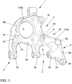
- FIG. 1 shows a wheel carrier according to the invention for a multi-link independent suspension.
- This wheel carrier comprises a wheel bearing receiving portion R for receiving a wheel bearing, not shown here.
- the wheel carrier comprises a first wishbone connection point 1 for connecting an upper transverse link, a second wishbone connection point 2 for connecting a rear lower wishbone, a third wishbone connection point 3 for connecting a front lower wishbone, and a trailing arm connection point 4 for connecting a trailing arm.
- the trailing arm connection point 4 is formed by a L Lucasslenkeranitatisarmabexcellent 5, which protrudes from a lying in the installed position of the wheel carrier on the third wishbone connection point 3 area to the associated trailing arm (not shown).
- the wheel carrier according to the invention is characterized in that the third wishbone connection point 3 is formed by a rear hinge pin receptacle 3a and a front hinge pin receptacle 3b, and that the front hinge pin receptacle 3b is designed as part of the L josslenkeranitatisarmabitess 5 and is thus integrated over the L josslenkerarmanitatisabrough 5 in the wheel ,
- a yoke is formed, which supports a cross arm hinged hinge pin on both sides and at the same time determines the axial position of the front lower arm on its main pivot axis X.
- the yoke is here designed to include a threaded portion for receiving a threaded hinge pin.
- the threaded portion is formed here in the rear hinge pin receptacle 3a.
- the wheel carrier has a brake caliper connecting portion 7, via which a brake caliper is connected.
- the brake caliper connecting portion 7 comprises a lower bore 8 passing through a root portion W thereof between the wheel bearing receiving portion R and the trailing arm connector arm portion 5.
- the L josslenkeranitatisarmabites 5 is designed so that it has a in the installed position substantially horizontally oriented upper arm leg 5a and a downwardly cranked down forearm leg 5b.
- the front hinge pin receptacle 3b is supported by a nosecone 5c which is concave on the inside, as can be seen here, which protrudes outward from the aforementioned forearm leg 5b, ie towards the wheel region.
- the trailing arm connection arm section 5 has a first screw connection point 5d and a second screw connection point 5e, the first screw connection point 5d lying in the transitional region between the upper arm leg 5a and the lower arm leg 5b.
- the second screw 5e is located in the lower end of the forearm leg 5b.
- the wheel carrier is made in this embodiment as an aluminum casting.
- the second wishbone connection point 2 is formed by a bushing section 2a, which is connected via a to the Radlagerungsabilityabrough R widening expiring framework structure with a first web 2b and a second web 2c to that material portion of the wheel carrier, which surrounds the wheel bearing region R. That section of material skirting the wheel bearing area is bordered on the edge by a web 9 which has a plurality of web sections 9a, 9b, 9c, 9d, 9e, 9f. These web portions 9a, 9b, 9c, 9d, 9e, 9f cause a stiffening of the wheel carrier and also a particularly rigid connection of the wishbone connection points 1, 2, 3 and the L josslenkeranitatisarmabitess. 5
- FIG. 2 the structure of the wheel carrier according to the invention is further illustrated. From this illustration, the realized by means of the inventive design of Lssenslenkeranitatisarmabitess 5 with integrated additional hinge pin receptacle 3b fork structure can be seen.
- This fork structure forms two contact surfaces 31, 32, between which the front lower control arm or its support formed with the inclusion of an elastomer bushing is received axially secured. The insertion of a corresponding threaded bolt takes place from direction P1.
- the threaded bolt is screwed into a preferably cut directly into the rear hinge pin receptacle 3a thread.
- By the threaded bolt of the forearm leg 5b is relatively stiff coupled to the rear hinge pin receptacle 3a.
- FIG. 3 the wheel carrier according to the invention together with associated wishbone 40 (front lower wishbone, also referred to as tie rod) is shown.
- the wishbone 40 is designed as a sheet metal part.
- a first outer sleeve 42 which is secured by press fit, weld or other structures in the handle 41.
- this outer sleeve 42 sits an elastomeric bushing.
- This Elastomerbuchse sits a support bush.
- This support sleeve is penetrated by the hinge pin, which sits as such on both sides in the two hinge pin receptacles 3a, 3b.
- the inventive concept makes it possible to realize a double-sided connection of the front, also referred to as tie rod wishbone in a wheel carrier.
- the invention is particularly suitable for under- or only partially steered Deutschenachssysteme.
- the invention can be used both in driven, as well as non-driven axle systems application.
- the concept according to the invention results in improved lightweight construction with simultaneously increased strength and rigidity of the component structure.
- the wheel carrier according to the invention can be manufactured as an aluminum cast component, preferably in the CPC method (mold back pressure method).
- the wheel carrier according to the invention can also be made of other casting materials and by other manufacturing methods.
- the concept according to the invention makes it possible to achieve a considerable increase in the structural strength. Under extreme loads (e.g., pothole traverse), the inventive concept provides large safety margins due to the significant increase in rigidity.
- the concept according to the invention furthermore offers a considerable potential for saving material through the widespread derivation of applied forces and a significant reduction in the bending moments.
- the basic construction is preferably carried out as an aluminum or cast iron part.
- the tie rod connection of the front lower tie rod is done in two sections.
- the type-existing trailing arm connection takes on an additional support function and causes a load distribution.
- the concept according to the invention makes it possible to dispense with previously required washers and nuts, and the hinge bolt provided for connecting the tie rod can be screwed directly into the solid material of the wheel carrier via a direct screw connection.
- the forces introduced via the front lower control arm are absorbed by the trailing arm connection section 5 and a rear hinge pin connection section and are dissipated in a wide range.
- the inventive concept results in a reduction of the unsprung mass and a reduction in the total vehicle weight and thus a positive contribution to reducing fuel consumption. Furthermore, a reduction of the preload forces in the tie rod connection is possible by the inventive concept. This makes it possible to achieve the required strength with smaller sizes directly into the solid material of the wheel carrier screwed screws.
- the wheel according to the invention can be built geound compared to previous designs cost and under low material usage and elimination of numerous standard and repeating parts.
- the tie rod can be included in the load transfer.
- the supporting structure created by incorporating the tie rod (or its bearing) forms a new load path, via which forces are transmitted both to the trailing arm and to the tie rod. This has the consequence that a load splitting is achieved by the resulting formation of a structure. Moments about train / pressure can be removed much more efficiently. The torsional load of the tie rod connection can be prevented.
- the construction according to the invention thus has a significantly increased lightweight construction potential.
- the use of materials can be significantly reduced with the same strength, since the newly created with the inclusion of the tie rod structure bending moments can remove significantly more material-efficient.
Claims (9)
- Support de roue pour une suspension indépendante à plusieurs bras, comprenant :- une portion de réception de palier de roue (R) pour recevoir un palier de roue ;- un premier point de liaison de bras oscillant transversal (1) pour la liaison d'un bras oscillant transversal supérieur ;- un deuxième point de liaison de bras oscillant transversal (2) pour la liaison d'un bras oscillant transversal inférieur arrière ;- un troisième point de liaison de bras oscillant transversal (3) avec un logement de boulon d'articulation pour la liaison d'un bras oscillant transversal avant inférieur (40) ; et- un point de liaison de bras oscillant longitudinal (4) pour la liaison d'un bras oscillant longitudinal, le point de liaison de bras oscillant longitudinal (4) étant formé au niveau d'une portion de bras de liaison de bras oscillant longitudinal (5) qui s'avance depuis une région située dans la position d'installation du support de roue au-delà du troisième point de liaison du bras oscillant transversal (3) jusqu'au bras oscillant longitudinal associé,caractérisé en ce que- le troisième point de liaison de bras oscillant transversal (3) est formé avec un logement de boulon d'articulation par un logement de boulon d'articulation arrière (3a) et un logement de boulon d'articulation avant (3b),- le logement de boulon d'articulation avant (3b) est incorporé dans le support de roue par le biais de la portion de bras de liaison de bras oscillant longitudinal (5), et- une fourche d'articulation est formée par le logement de boulon d'articulation arrière (3a) et le logement de boulon d'articulation avant (3b) en formant la portion de bras de liaison de bras oscillant longitudinal (5), par le biais de laquelle fourche d'articulation un boulon d'articulation supportant le bras oscillant transversal inférieur avant (40) est supporté radialement des deux côtés dans les deux logements de boulon d'articulation (3a, 3b).
- Support de roue selon la revendication 1, caractérisé en ce que la fourche d'articulation est configurée de telle sorte que la position axiale du bras oscillant transversal inférieur (40) sur son axe de pivotement principal (X) soit fixée par ladite fourche d'articulation en collaboration avec une douille d'articulation.
- Support de roue selon la revendication 1 ou 2, caractérisé en ce que la fourche d'articulation comprend une portion filetée pour recevoir un boulon d'articulation pourvu d'un filetage.
- Support de roue selon la revendication 3, caractérisé en ce que la portion filetée est réalisée dans le logement de boulon d'articulation arrière (3a).
- Support de roue selon l'une quelconque des revendications 1 à 4, caractérisé en ce que le support de roue présente une portion de liaison d'étrier de frein (7) pour la liaison d'un étrier de frein, la portion de liaison d'étrier de frein (7) présentant un alésage (8) qui traverse une région d'embase (W) de celle-ci, située entre la portion de réception de palier de roue (R) et la portion de bras de liaison de bras oscillant longitudinal (5).
- Support de roue selon l'une quelconque des revendications 1 à 5, caractérisé en ce que la portion de bras de liaison de bras oscillant longitudinal (5) présente une branche de bras supérieure (5a) s'étendant dans la position d'installation de manière orientée essentiellement horizontalement et une branche de bras inférieure (5b) s'étendant de manière coudée vers le bas par rapport à celle-ci.
- Support de roue selon la revendication 6, caractérisé en ce que le logement de boulon d'articulation avant (3b) est formé par une structure de nez qui fait saillie vers l'extérieur depuis ladite branche de bras inférieure (5b).
- Support de roue selon la revendication 6 ou 7, caractérisé en ce que la portion de bras de liaison de bras oscillant longitudinal (5) présente un premier point de vissage (5d) et un deuxième point de vissage (5e), le premier point de vissage (5d) étant situé dans la région de transition entre la branche de bras supérieure (5a) et la branche de bras inférieure (5b), et le deuxième point de vissage (5e) étant situé dans la région d'extrémité inférieure de la branche de bras inférieure (5b).
- Suspension indépendante à plusieurs bras comprenant un support de roue selon l'une quelconque des revendications précédentes.
Applications Claiming Priority (2)
| Application Number | Priority Date | Filing Date | Title |
|---|---|---|---|
| DE102010011487A DE102010011487A1 (de) | 2010-03-16 | 2010-03-16 | Radträger für eine Einzelradaufhängung |
| PCT/EP2011/000805 WO2011113514A1 (fr) | 2010-03-16 | 2011-02-19 | Support de roue pour une suspension à roues indépendantes à bras oscillants multiples |
Publications (2)
| Publication Number | Publication Date |
|---|---|
| EP2547539A1 EP2547539A1 (fr) | 2013-01-23 |
| EP2547539B1 true EP2547539B1 (fr) | 2017-04-12 |
Family
ID=43983724
Family Applications (1)
| Application Number | Title | Priority Date | Filing Date |
|---|---|---|---|
| EP11706173.9A Active EP2547539B1 (fr) | 2010-03-16 | 2011-02-19 | Supports de roue pour suspension independant ayant plusieurs bras oscillants |
Country Status (4)
| Country | Link |
|---|---|
| EP (1) | EP2547539B1 (fr) |
| CN (1) | CN102802970B (fr) |
| DE (1) | DE102010011487A1 (fr) |
| WO (1) | WO2011113514A1 (fr) |
Families Citing this family (10)
| Publication number | Priority date | Publication date | Assignee | Title |
|---|---|---|---|---|
| DE102013006241A1 (de) | 2013-04-11 | 2014-10-16 | Volkswagen Aktiengesellschaft | Radträger für die Radaufhängung eines Fahrzeugs |
| DE102013217218B4 (de) * | 2013-08-28 | 2021-05-27 | Volkswagen Aktiengesellschaft | Schwenklager bzw. Radträger |
| CN106143606B (zh) * | 2015-04-28 | 2019-04-30 | 长城汽车股份有限公司 | 一种车辆的转向节、悬架装置 |
| CN108136897A (zh) * | 2015-07-30 | 2018-06-08 | 庞巴迪动力产品公司 | 用于车辆悬架总成的转向节 |
| KR101826566B1 (ko) | 2016-07-12 | 2018-02-07 | 현대자동차 주식회사 | 차량의 현가장치용 캐리어 |
| CN107128365A (zh) * | 2017-04-22 | 2017-09-05 | 福州六和机械有限公司 | 一种转向节接触式防误方法 |
| DE102017214190A1 (de) | 2017-08-15 | 2019-02-21 | Ford Global Technologies, Llc | Lageranordnung für einen Kraftwagen |
| DE102018217956A1 (de) * | 2018-10-19 | 2020-04-23 | Thyssenkrupp Ag | Dämpferstelze aus zwei Halbschalen |
| DE102019113939A1 (de) * | 2019-05-24 | 2020-11-26 | Knorr-Bremse Systeme für Nutzfahrzeuge GmbH | Achsschenkel eines Nutzfahrzeuges |
| CN112124421A (zh) * | 2020-09-27 | 2020-12-25 | 东风柳州汽车有限公司 | 一种四连杆独立悬架后转向节 |
Family Cites Families (12)
| Publication number | Priority date | Publication date | Assignee | Title |
|---|---|---|---|---|
| DE19737715A1 (de) | 1997-08-29 | 1999-03-04 | Volkswagen Ag | Einzelradaufhängung einer Hinterachse |
| US6138357A (en) * | 1997-12-08 | 2000-10-31 | Ford Global Technologies, Inc. | Method of making knuckle assembly |
| DE10018764A1 (de) * | 2000-04-15 | 2001-10-18 | Volkswagen Ag | Radaufhängung |
| US6932366B2 (en) * | 2002-11-19 | 2005-08-23 | Ford Global Technologies, Llc | Automotive camber adjust mechanism |
| DE10336798A1 (de) * | 2003-08-11 | 2005-03-10 | Volkswagen Ag | Radträger mit Bremsenabdeckblech |
| DE10346280A1 (de) * | 2003-10-06 | 2005-05-12 | Volkswagen Ag | Radträger für eine Kraftfahrzeug-Radaufhängung |
| DE20319147U1 (de) * | 2003-12-09 | 2004-04-01 | Zf Friedrichshafen Ag | Radträgereinheit für ein Kraftfahrzeug |
| DE102004024899B4 (de) * | 2004-05-19 | 2020-10-08 | Volkswagen Ag | Vierlenker-Radaufhängung für eine Hinterachse |
| US7431315B2 (en) * | 2005-07-11 | 2008-10-07 | Ford Global Technologies, Llc | Vehicle suspension system with wheel support knuckle and trailing arm attached to toe link |
| DE102006055819A1 (de) * | 2006-11-27 | 2008-05-29 | Ford Global Technologies, LLC, Dearborn | Radaufhängung mit beeinflußbarer Vorspur |
| JP2008195296A (ja) * | 2007-02-14 | 2008-08-28 | Honda Motor Co Ltd | サスペンション装置 |
| DE102007024586A1 (de) * | 2007-05-25 | 2008-11-27 | Audi Ag | Radaufhängung für Kraftfahrzeuge |
-
2010
- 2010-03-16 DE DE102010011487A patent/DE102010011487A1/de not_active Withdrawn
-
2011
- 2011-02-19 EP EP11706173.9A patent/EP2547539B1/fr active Active
- 2011-02-19 WO PCT/EP2011/000805 patent/WO2011113514A1/fr active Application Filing
- 2011-02-19 CN CN201180014177.1A patent/CN102802970B/zh active Active
Also Published As
| Publication number | Publication date |
|---|---|
| WO2011113514A1 (fr) | 2011-09-22 |
| CN102802970B (zh) | 2016-03-30 |
| DE102010011487A1 (de) | 2011-09-22 |
| CN102802970A (zh) | 2012-11-28 |
| EP2547539A1 (fr) | 2013-01-23 |
Similar Documents
| Publication | Publication Date | Title |
|---|---|---|
| EP2547539B1 (fr) | Supports de roue pour suspension independant ayant plusieurs bras oscillants | |
| EP1912806B2 (fr) | Bras oscillant de suspension | |
| DE10053411B4 (de) | Fahrzeugachse | |
| EP2329159B1 (fr) | Dispositif de liaison d'arbre creux | |
| EP0909693B1 (fr) | Fusée d'essieu | |
| EP2038157B1 (fr) | Cadre de châssis d'un véhicule ferroviaire | |
| EP2270356B1 (fr) | Douille élastique | |
| WO2011147411A2 (fr) | Module d'essieu, en particulier essieu à bras combinés | |
| DE102012107515B4 (de) | Aktives geometrie-gesteuertes aufhängungssystem | |
| DE3902407C1 (en) | Bearing | |
| DE102011016628A1 (de) | Schwenklager | |
| EP0806310B1 (fr) | Suspension indépendante pour une roue directrice à suspension pneumatique d'un autobus ou camion | |
| WO2019042634A1 (fr) | Amortisseur de vibrations dans la suspension de roue d'un véhicule | |
| WO2008098550A1 (fr) | Essieu rigide pour véhicule utilitaire | |
| EP3153737B1 (fr) | Palier de châssis | |
| DE3809995A1 (de) | Hintere aufhaengungseinrichtung fuer motorfahrzeuge | |
| DE102017214190A1 (de) | Lageranordnung für einen Kraftwagen | |
| DE102017211277B4 (de) | Radaufhängung für ein Kraftfahrzeug | |
| DE102015216839A1 (de) | Querlenker für eine Radaufhängung eines Kraftfahrzeugs | |
| WO2019206622A1 (fr) | Suspension de véhicule automobile | |
| EP2821263B1 (fr) | Axe pour un véhicule utilitaire, essieu et véhicule utilitaire équipé d'un tel axe | |
| DE102016221964B4 (de) | Hinterradaufhängung, insbesondere Integral-Hinterradaufhängung mit Luftfeder für ein Fahrzeug | |
| DE102006003074B3 (de) | Fahrwerksanordnung | |
| DE102005058565A1 (de) | Nabenträger, sowie hiermit ausgestattete Radaufhängung | |
| DE202015106075U1 (de) | Querlenker für eine Radaufhängung eines Kraftfahrzeugs |
Legal Events
| Date | Code | Title | Description |
|---|---|---|---|
| PUAI | Public reference made under article 153(3) epc to a published international application that has entered the european phase |
Free format text: ORIGINAL CODE: 0009012 |
|
| 17P | Request for examination filed |
Effective date: 20121016 |
|
| AK | Designated contracting states |
Kind code of ref document: A1 Designated state(s): AL AT BE BG CH CY CZ DE DK EE ES FI FR GB GR HR HU IE IS IT LI LT LU LV MC MK MT NL NO PL PT RO RS SE SI SK SM TR |
|
| DAX | Request for extension of the european patent (deleted) | ||
| GRAJ | Information related to disapproval of communication of intention to grant by the applicant or resumption of examination proceedings by the epo deleted |
Free format text: ORIGINAL CODE: EPIDOSDIGR1 |
|
| GRAP | Despatch of communication of intention to grant a patent |
Free format text: ORIGINAL CODE: EPIDOSNIGR1 |
|
| GRAP | Despatch of communication of intention to grant a patent |
Free format text: ORIGINAL CODE: EPIDOSNIGR1 |
|
| INTG | Intention to grant announced |
Effective date: 20170102 |
|
| GRAS | Grant fee paid |
Free format text: ORIGINAL CODE: EPIDOSNIGR3 |
|
| GRAA | (expected) grant |
Free format text: ORIGINAL CODE: 0009210 |
|
| AK | Designated contracting states |
Kind code of ref document: B1 Designated state(s): AL AT BE BG CH CY CZ DE DK EE ES FI FR GB GR HR HU IE IS IT LI LT LU LV MC MK MT NL NO PL PT RO RS SE SI SK SM TR |
|
| REG | Reference to a national code |
Ref country code: GB Ref legal event code: FG4D Free format text: NOT ENGLISH |
|
| REG | Reference to a national code |
Ref country code: CH Ref legal event code: EP |
|
| REG | Reference to a national code |
Ref country code: IE Ref legal event code: FG4D Free format text: LANGUAGE OF EP DOCUMENT: GERMAN |
|
| REG | Reference to a national code |
Ref country code: AT Ref legal event code: REF Ref document number: 883477 Country of ref document: AT Kind code of ref document: T Effective date: 20170515 |
|
| REG | Reference to a national code |
Ref country code: DE Ref legal event code: R096 Ref document number: 502011012021 Country of ref document: DE |
|
| REG | Reference to a national code |
Ref country code: NL Ref legal event code: MP Effective date: 20170412 |
|
| REG | Reference to a national code |
Ref country code: LT Ref legal event code: MG4D |
|
| PG25 | Lapsed in a contracting state [announced via postgrant information from national office to epo] |
Ref country code: NL Free format text: LAPSE BECAUSE OF FAILURE TO SUBMIT A TRANSLATION OF THE DESCRIPTION OR TO PAY THE FEE WITHIN THE PRESCRIBED TIME-LIMIT Effective date: 20170412 |
|
| PG25 | Lapsed in a contracting state [announced via postgrant information from national office to epo] |
Ref country code: NO Free format text: LAPSE BECAUSE OF FAILURE TO SUBMIT A TRANSLATION OF THE DESCRIPTION OR TO PAY THE FEE WITHIN THE PRESCRIBED TIME-LIMIT Effective date: 20170712 Ref country code: HR Free format text: LAPSE BECAUSE OF FAILURE TO SUBMIT A TRANSLATION OF THE DESCRIPTION OR TO PAY THE FEE WITHIN THE PRESCRIBED TIME-LIMIT Effective date: 20170412 Ref country code: FI Free format text: LAPSE BECAUSE OF FAILURE TO SUBMIT A TRANSLATION OF THE DESCRIPTION OR TO PAY THE FEE WITHIN THE PRESCRIBED TIME-LIMIT Effective date: 20170412 Ref country code: GR Free format text: LAPSE BECAUSE OF FAILURE TO SUBMIT A TRANSLATION OF THE DESCRIPTION OR TO PAY THE FEE WITHIN THE PRESCRIBED TIME-LIMIT Effective date: 20170713 Ref country code: LT Free format text: LAPSE BECAUSE OF FAILURE TO SUBMIT A TRANSLATION OF THE DESCRIPTION OR TO PAY THE FEE WITHIN THE PRESCRIBED TIME-LIMIT Effective date: 20170412 Ref country code: ES Free format text: LAPSE BECAUSE OF FAILURE TO SUBMIT A TRANSLATION OF THE DESCRIPTION OR TO PAY THE FEE WITHIN THE PRESCRIBED TIME-LIMIT Effective date: 20170412 |
|
| PG25 | Lapsed in a contracting state [announced via postgrant information from national office to epo] |
Ref country code: BG Free format text: LAPSE BECAUSE OF FAILURE TO SUBMIT A TRANSLATION OF THE DESCRIPTION OR TO PAY THE FEE WITHIN THE PRESCRIBED TIME-LIMIT Effective date: 20170712 Ref country code: IS Free format text: LAPSE BECAUSE OF FAILURE TO SUBMIT A TRANSLATION OF THE DESCRIPTION OR TO PAY THE FEE WITHIN THE PRESCRIBED TIME-LIMIT Effective date: 20170812 Ref country code: LV Free format text: LAPSE BECAUSE OF FAILURE TO SUBMIT A TRANSLATION OF THE DESCRIPTION OR TO PAY THE FEE WITHIN THE PRESCRIBED TIME-LIMIT Effective date: 20170412 Ref country code: SE Free format text: LAPSE BECAUSE OF FAILURE TO SUBMIT A TRANSLATION OF THE DESCRIPTION OR TO PAY THE FEE WITHIN THE PRESCRIBED TIME-LIMIT Effective date: 20170412 Ref country code: RS Free format text: LAPSE BECAUSE OF FAILURE TO SUBMIT A TRANSLATION OF THE DESCRIPTION OR TO PAY THE FEE WITHIN THE PRESCRIBED TIME-LIMIT Effective date: 20170412 Ref country code: PL Free format text: LAPSE BECAUSE OF FAILURE TO SUBMIT A TRANSLATION OF THE DESCRIPTION OR TO PAY THE FEE WITHIN THE PRESCRIBED TIME-LIMIT Effective date: 20170412 |
|
| REG | Reference to a national code |
Ref country code: DE Ref legal event code: R097 Ref document number: 502011012021 Country of ref document: DE |
|
| PG25 | Lapsed in a contracting state [announced via postgrant information from national office to epo] |
Ref country code: RO Free format text: LAPSE BECAUSE OF FAILURE TO SUBMIT A TRANSLATION OF THE DESCRIPTION OR TO PAY THE FEE WITHIN THE PRESCRIBED TIME-LIMIT Effective date: 20170412 Ref country code: EE Free format text: LAPSE BECAUSE OF FAILURE TO SUBMIT A TRANSLATION OF THE DESCRIPTION OR TO PAY THE FEE WITHIN THE PRESCRIBED TIME-LIMIT Effective date: 20170412 Ref country code: SK Free format text: LAPSE BECAUSE OF FAILURE TO SUBMIT A TRANSLATION OF THE DESCRIPTION OR TO PAY THE FEE WITHIN THE PRESCRIBED TIME-LIMIT Effective date: 20170412 Ref country code: DK Free format text: LAPSE BECAUSE OF FAILURE TO SUBMIT A TRANSLATION OF THE DESCRIPTION OR TO PAY THE FEE WITHIN THE PRESCRIBED TIME-LIMIT Effective date: 20170412 |
|
| PLBE | No opposition filed within time limit |
Free format text: ORIGINAL CODE: 0009261 |
|
| STAA | Information on the status of an ep patent application or granted ep patent |
Free format text: STATUS: NO OPPOSITION FILED WITHIN TIME LIMIT |
|
| REG | Reference to a national code |
Ref country code: FR Ref legal event code: PLFP Year of fee payment: 8 |
|
| PG25 | Lapsed in a contracting state [announced via postgrant information from national office to epo] |
Ref country code: IT Free format text: LAPSE BECAUSE OF FAILURE TO SUBMIT A TRANSLATION OF THE DESCRIPTION OR TO PAY THE FEE WITHIN THE PRESCRIBED TIME-LIMIT Effective date: 20170412 Ref country code: SM Free format text: LAPSE BECAUSE OF FAILURE TO SUBMIT A TRANSLATION OF THE DESCRIPTION OR TO PAY THE FEE WITHIN THE PRESCRIBED TIME-LIMIT Effective date: 20170412 |
|
| 26N | No opposition filed |
Effective date: 20180115 |
|
| PG25 | Lapsed in a contracting state [announced via postgrant information from national office to epo] |
Ref country code: SI Free format text: LAPSE BECAUSE OF FAILURE TO SUBMIT A TRANSLATION OF THE DESCRIPTION OR TO PAY THE FEE WITHIN THE PRESCRIBED TIME-LIMIT Effective date: 20170412 |
|
| REG | Reference to a national code |
Ref country code: CH Ref legal event code: PL |
|
| PG25 | Lapsed in a contracting state [announced via postgrant information from national office to epo] |
Ref country code: MC Free format text: LAPSE BECAUSE OF FAILURE TO SUBMIT A TRANSLATION OF THE DESCRIPTION OR TO PAY THE FEE WITHIN THE PRESCRIBED TIME-LIMIT Effective date: 20170412 Ref country code: MT Free format text: LAPSE BECAUSE OF FAILURE TO SUBMIT A TRANSLATION OF THE DESCRIPTION OR TO PAY THE FEE WITHIN THE PRESCRIBED TIME-LIMIT Effective date: 20170412 |
|
| REG | Reference to a national code |
Ref country code: IE Ref legal event code: MM4A |
|
| REG | Reference to a national code |
Ref country code: BE Ref legal event code: MM Effective date: 20180228 |
|
| PG25 | Lapsed in a contracting state [announced via postgrant information from national office to epo] |
Ref country code: CH Free format text: LAPSE BECAUSE OF NON-PAYMENT OF DUE FEES Effective date: 20180228 Ref country code: LU Free format text: LAPSE BECAUSE OF NON-PAYMENT OF DUE FEES Effective date: 20180219 Ref country code: LI Free format text: LAPSE BECAUSE OF NON-PAYMENT OF DUE FEES Effective date: 20180228 |
|
| PG25 | Lapsed in a contracting state [announced via postgrant information from national office to epo] |
Ref country code: IE Free format text: LAPSE BECAUSE OF NON-PAYMENT OF DUE FEES Effective date: 20180219 |
|
| PG25 | Lapsed in a contracting state [announced via postgrant information from national office to epo] |
Ref country code: BE Free format text: LAPSE BECAUSE OF NON-PAYMENT OF DUE FEES Effective date: 20180228 |
|
| REG | Reference to a national code |
Ref country code: AT Ref legal event code: MM01 Ref document number: 883477 Country of ref document: AT Kind code of ref document: T Effective date: 20180219 |
|
| PG25 | Lapsed in a contracting state [announced via postgrant information from national office to epo] |
Ref country code: AT Free format text: LAPSE BECAUSE OF NON-PAYMENT OF DUE FEES Effective date: 20180219 |
|
| PG25 | Lapsed in a contracting state [announced via postgrant information from national office to epo] |
Ref country code: TR Free format text: LAPSE BECAUSE OF FAILURE TO SUBMIT A TRANSLATION OF THE DESCRIPTION OR TO PAY THE FEE WITHIN THE PRESCRIBED TIME-LIMIT Effective date: 20170412 |
|
| PG25 | Lapsed in a contracting state [announced via postgrant information from national office to epo] |
Ref country code: PT Free format text: LAPSE BECAUSE OF FAILURE TO SUBMIT A TRANSLATION OF THE DESCRIPTION OR TO PAY THE FEE WITHIN THE PRESCRIBED TIME-LIMIT Effective date: 20170412 Ref country code: HU Free format text: LAPSE BECAUSE OF FAILURE TO SUBMIT A TRANSLATION OF THE DESCRIPTION OR TO PAY THE FEE WITHIN THE PRESCRIBED TIME-LIMIT; INVALID AB INITIO Effective date: 20110219 |
|
| PG25 | Lapsed in a contracting state [announced via postgrant information from national office to epo] |
Ref country code: CY Free format text: LAPSE BECAUSE OF FAILURE TO SUBMIT A TRANSLATION OF THE DESCRIPTION OR TO PAY THE FEE WITHIN THE PRESCRIBED TIME-LIMIT Effective date: 20170412 Ref country code: MK Free format text: LAPSE BECAUSE OF NON-PAYMENT OF DUE FEES Effective date: 20170412 |
|
| PG25 | Lapsed in a contracting state [announced via postgrant information from national office to epo] |
Ref country code: AL Free format text: LAPSE BECAUSE OF FAILURE TO SUBMIT A TRANSLATION OF THE DESCRIPTION OR TO PAY THE FEE WITHIN THE PRESCRIBED TIME-LIMIT Effective date: 20170412 |
|
| PGFP | Annual fee paid to national office [announced via postgrant information from national office to epo] |
Ref country code: FR Payment date: 20230223 Year of fee payment: 13 Ref country code: CZ Payment date: 20230216 Year of fee payment: 13 |
|
| P01 | Opt-out of the competence of the unified patent court (upc) registered |
Effective date: 20230523 |
|
| PGFP | Annual fee paid to national office [announced via postgrant information from national office to epo] |
Ref country code: DE Payment date: 20240229 Year of fee payment: 14 Ref country code: CZ Payment date: 20240206 Year of fee payment: 14 Ref country code: GB Payment date: 20240220 Year of fee payment: 14 |