EP2546898A2 - Phosphor adhesive sheet, light emitting diode element including phosphor layer, light emitting diode device, and producing methods thereof - Google Patents
Phosphor adhesive sheet, light emitting diode element including phosphor layer, light emitting diode device, and producing methods thereof Download PDFInfo
- Publication number
- EP2546898A2 EP2546898A2 EP12172382A EP12172382A EP2546898A2 EP 2546898 A2 EP2546898 A2 EP 2546898A2 EP 12172382 A EP12172382 A EP 12172382A EP 12172382 A EP12172382 A EP 12172382A EP 2546898 A2 EP2546898 A2 EP 2546898A2
- Authority
- EP
- European Patent Office
- Prior art keywords
- light emitting
- emitting diode
- phosphor
- resin composition
- silicone resin
- Prior art date
- Legal status (The legal status is an assumption and is not a legal conclusion. Google has not performed a legal analysis and makes no representation as to the accuracy of the status listed.)
- Withdrawn
Links
- OAICVXFJPJFONN-UHFFFAOYSA-N Phosphorus Chemical compound [P] OAICVXFJPJFONN-UHFFFAOYSA-N 0.000 title claims abstract description 534
- 239000000853 adhesive Substances 0.000 title claims abstract description 157
- 230000001070 adhesive effect Effects 0.000 title claims abstract description 157
- 238000000034 method Methods 0.000 title description 54
- 239000010410 layer Substances 0.000 claims abstract description 316
- 239000011342 resin composition Substances 0.000 claims abstract description 283
- 229920002050 silicone resin Polymers 0.000 claims abstract description 280
- 239000012790 adhesive layer Substances 0.000 claims abstract description 233
- 229920001187 thermosetting polymer Polymers 0.000 claims abstract description 66
- 229920001169 thermoplastic Polymers 0.000 claims abstract description 49
- 239000004416 thermosoftening plastic Substances 0.000 claims abstract description 49
- 238000010438 heat treatment Methods 0.000 claims description 77
- 238000004519 manufacturing process Methods 0.000 claims description 76
- 239000000919 ceramic Substances 0.000 claims description 35
- 229920005989 resin Polymers 0.000 claims description 31
- 239000011347 resin Substances 0.000 claims description 31
- 238000011049 filling Methods 0.000 claims description 4
- 238000001816 cooling Methods 0.000 claims description 2
- 125000003342 alkenyl group Chemical group 0.000 description 166
- -1 (Sr Chemical compound 0.000 description 152
- 229920001296 polysiloxane Polymers 0.000 description 151
- POPVULPQMGGUMJ-UHFFFAOYSA-N octasilsesquioxane cage Chemical compound O1[SiH](O[SiH](O2)O[SiH](O3)O4)O[SiH]4O[SiH]4O[SiH]1O[SiH]2O[SiH]3O4 POPVULPQMGGUMJ-UHFFFAOYSA-N 0.000 description 103
- 150000002430 hydrocarbons Chemical group 0.000 description 70
- 238000006459 hydrosilylation reaction Methods 0.000 description 65
- 238000006243 chemical reaction Methods 0.000 description 57
- 239000003054 catalyst Substances 0.000 description 46
- 125000003277 amino group Chemical group 0.000 description 41
- 229920006136 organohydrogenpolysiloxane Polymers 0.000 description 41
- 238000002156 mixing Methods 0.000 description 40
- YXFVVABEGXRONW-UHFFFAOYSA-N Toluene Chemical compound CC1=CC=CC=C1 YXFVVABEGXRONW-UHFFFAOYSA-N 0.000 description 39
- 125000002496 methyl group Chemical group [H]C([H])([H])* 0.000 description 34
- 239000000047 product Substances 0.000 description 34
- 239000007787 solid Substances 0.000 description 33
- 125000005442 diisocyanate group Chemical group 0.000 description 27
- 239000002243 precursor Substances 0.000 description 27
- 125000002887 hydroxy group Chemical group [H]O* 0.000 description 22
- VLKZOEOYAKHREP-UHFFFAOYSA-N n-Hexane Chemical compound CCCCCC VLKZOEOYAKHREP-UHFFFAOYSA-N 0.000 description 21
- KPUWHANPEXNPJT-UHFFFAOYSA-N disiloxane Chemical class [SiH3]O[SiH3] KPUWHANPEXNPJT-UHFFFAOYSA-N 0.000 description 17
- IQPQWNKOIGAROB-UHFFFAOYSA-N isocyanate group Chemical group [N-]=C=O IQPQWNKOIGAROB-UHFFFAOYSA-N 0.000 description 17
- 239000000203 mixture Substances 0.000 description 17
- 239000002904 solvent Substances 0.000 description 16
- 239000001257 hydrogen Substances 0.000 description 15
- 229910052739 hydrogen Inorganic materials 0.000 description 15
- 239000007788 liquid Substances 0.000 description 15
- 125000000391 vinyl group Chemical group [H]C([*])=C([H])[H] 0.000 description 15
- 239000000470 constituent Substances 0.000 description 14
- BASFCYQUMIYNBI-UHFFFAOYSA-N platinum Chemical compound [Pt] BASFCYQUMIYNBI-UHFFFAOYSA-N 0.000 description 14
- UFHFLCQGNIYNRP-UHFFFAOYSA-N Hydrogen Chemical compound [H][H] UFHFLCQGNIYNRP-UHFFFAOYSA-N 0.000 description 13
- XEKOWRVHYACXOJ-UHFFFAOYSA-N Ethyl acetate Chemical compound CCOC(C)=O XEKOWRVHYACXOJ-UHFFFAOYSA-N 0.000 description 12
- 125000004432 carbon atom Chemical group C* 0.000 description 12
- 230000000052 comparative effect Effects 0.000 description 12
- 125000004435 hydrogen atom Chemical group [H]* 0.000 description 12
- 238000005160 1H NMR spectroscopy Methods 0.000 description 11
- 230000009257 reactivity Effects 0.000 description 11
- 229930195734 saturated hydrocarbon Natural products 0.000 description 11
- 125000002029 aromatic hydrocarbon group Chemical group 0.000 description 10
- 230000002950 deficient Effects 0.000 description 10
- 230000003287 optical effect Effects 0.000 description 10
- 125000001997 phenyl group Chemical group [H]C1=C([H])C([H])=C(*)C([H])=C1[H] 0.000 description 10
- ZWEHNKRNPOVVGH-UHFFFAOYSA-N 2-Butanone Chemical compound CCC(C)=O ZWEHNKRNPOVVGH-UHFFFAOYSA-N 0.000 description 9
- OKKJLVBELUTLKV-UHFFFAOYSA-N Methanol Chemical compound OC OKKJLVBELUTLKV-UHFFFAOYSA-N 0.000 description 9
- 150000004945 aromatic hydrocarbons Chemical class 0.000 description 8
- 238000006482 condensation reaction Methods 0.000 description 8
- 239000000463 material Substances 0.000 description 8
- 229910052697 platinum Inorganic materials 0.000 description 8
- 125000000217 alkyl group Chemical group 0.000 description 7
- 238000004132 cross linking Methods 0.000 description 7
- 230000008034 disappearance Effects 0.000 description 7
- 238000007689 inspection Methods 0.000 description 7
- 238000005259 measurement Methods 0.000 description 7
- 239000000758 substrate Substances 0.000 description 7
- XUIMIQQOPSSXEZ-UHFFFAOYSA-N Silicon Chemical group [Si] XUIMIQQOPSSXEZ-UHFFFAOYSA-N 0.000 description 6
- 150000001875 compounds Chemical class 0.000 description 6
- 230000018044 dehydration Effects 0.000 description 6
- 238000006297 dehydration reaction Methods 0.000 description 6
- 239000002245 particle Substances 0.000 description 6
- 229920002554 vinyl polymer Polymers 0.000 description 6
- 239000000654 additive Substances 0.000 description 5
- 230000000996 additive effect Effects 0.000 description 5
- 229910010293 ceramic material Inorganic materials 0.000 description 5
- 238000005520 cutting process Methods 0.000 description 5
- 230000003247 decreasing effect Effects 0.000 description 5
- 125000000962 organic group Chemical group 0.000 description 5
- 239000000843 powder Substances 0.000 description 5
- 229910052710 silicon Inorganic materials 0.000 description 5
- 239000004820 Pressure-sensitive adhesive Substances 0.000 description 4
- BOTDANWDWHJENH-UHFFFAOYSA-N Tetraethyl orthosilicate Chemical compound CCO[Si](OCC)(OCC)OCC BOTDANWDWHJENH-UHFFFAOYSA-N 0.000 description 4
- 238000007259 addition reaction Methods 0.000 description 4
- 150000001338 aliphatic hydrocarbons Chemical class 0.000 description 4
- 230000000712 assembly Effects 0.000 description 4
- 238000000429 assembly Methods 0.000 description 4
- 239000011230 binding agent Substances 0.000 description 4
- IJOOHPMOJXWVHK-UHFFFAOYSA-N chlorotrimethylsilane Chemical compound C[Si](C)(C)Cl IJOOHPMOJXWVHK-UHFFFAOYSA-N 0.000 description 4
- 150000002148 esters Chemical class 0.000 description 4
- 230000007062 hydrolysis Effects 0.000 description 4
- 238000006460 hydrolysis reaction Methods 0.000 description 4
- 229910052757 nitrogen Inorganic materials 0.000 description 4
- 239000003960 organic solvent Substances 0.000 description 4
- 238000002360 preparation method Methods 0.000 description 4
- 239000003566 sealing material Substances 0.000 description 4
- 229920002379 silicone rubber Polymers 0.000 description 4
- 239000004925 Acrylic resin Substances 0.000 description 3
- 229920000178 Acrylic resin Polymers 0.000 description 3
- UHOVQNZJYSORNB-UHFFFAOYSA-N Benzene Chemical compound C1=CC=CC=C1 UHOVQNZJYSORNB-UHFFFAOYSA-N 0.000 description 3
- 125000003545 alkoxy group Chemical group 0.000 description 3
- 125000002947 alkylene group Chemical group 0.000 description 3
- LSXWFXONGKSEMY-UHFFFAOYSA-N di-tert-butyl peroxide Chemical compound CC(C)(C)OOC(C)(C)C LSXWFXONGKSEMY-UHFFFAOYSA-N 0.000 description 3
- 238000009792 diffusion process Methods 0.000 description 3
- 125000000524 functional group Chemical group 0.000 description 3
- 239000002223 garnet Substances 0.000 description 3
- 229910052698 phosphorus Inorganic materials 0.000 description 3
- 239000000376 reactant Substances 0.000 description 3
- 238000005245 sintering Methods 0.000 description 3
- DVKJHBMWWAPEIU-UHFFFAOYSA-N toluene 2,4-diisocyanate Chemical compound CC1=CC=C(N=C=O)C=C1N=C=O DVKJHBMWWAPEIU-UHFFFAOYSA-N 0.000 description 3
- 229910052727 yttrium Inorganic materials 0.000 description 3
- NAWXUBYGYWOOIX-SFHVURJKSA-N (2s)-2-[[4-[2-(2,4-diaminoquinazolin-6-yl)ethyl]benzoyl]amino]-4-methylidenepentanedioic acid Chemical compound C1=CC2=NC(N)=NC(N)=C2C=C1CCC1=CC=C(C(=O)N[C@@H](CC(=C)C(O)=O)C(O)=O)C=C1 NAWXUBYGYWOOIX-SFHVURJKSA-N 0.000 description 2
- DMWVYCCGCQPJEA-UHFFFAOYSA-N 2,5-bis(tert-butylperoxy)-2,5-dimethylhexane Chemical compound CC(C)(C)OOC(C)(C)CCC(C)(C)OOC(C)(C)C DMWVYCCGCQPJEA-UHFFFAOYSA-N 0.000 description 2
- 125000003903 2-propenyl group Chemical group [H]C([*])([H])C([H])=C([H])[H] 0.000 description 2
- IJGRMHOSHXDMSA-UHFFFAOYSA-N Atomic nitrogen Chemical compound N#N IJGRMHOSHXDMSA-UHFFFAOYSA-N 0.000 description 2
- 229920002799 BoPET Polymers 0.000 description 2
- IRIAEXORFWYRCZ-UHFFFAOYSA-N Butylbenzyl phthalate Chemical compound CCCCOC(=O)C1=CC=CC=C1C(=O)OCC1=CC=CC=C1 IRIAEXORFWYRCZ-UHFFFAOYSA-N 0.000 description 2
- 229910052693 Europium Inorganic materials 0.000 description 2
- 239000005057 Hexamethylene diisocyanate Substances 0.000 description 2
- XEEYBQQBJWHFJM-UHFFFAOYSA-N Iron Chemical compound [Fe] XEEYBQQBJWHFJM-UHFFFAOYSA-N 0.000 description 2
- 239000005058 Isophorone diisocyanate Substances 0.000 description 2
- CSNNHWWHGAXBCP-UHFFFAOYSA-L Magnesium sulfate Chemical compound [Mg+2].[O-][S+2]([O-])([O-])[O-] CSNNHWWHGAXBCP-UHFFFAOYSA-L 0.000 description 2
- PXHVJJICTQNCMI-UHFFFAOYSA-N Nickel Chemical compound [Ni] PXHVJJICTQNCMI-UHFFFAOYSA-N 0.000 description 2
- KDLHZDBZIXYQEI-UHFFFAOYSA-N Palladium Chemical compound [Pd] KDLHZDBZIXYQEI-UHFFFAOYSA-N 0.000 description 2
- 229920004482 WACKER® Polymers 0.000 description 2
- 229910052782 aluminium Inorganic materials 0.000 description 2
- 125000003118 aryl group Chemical group 0.000 description 2
- 125000001797 benzyl group Chemical group [H]C1=C([H])C([H])=C(C([H])=C1[H])C([H])([H])* 0.000 description 2
- 125000000484 butyl group Chemical group [H]C([*])([H])C([H])([H])C([H])([H])C([H])([H])[H] 0.000 description 2
- 239000000460 chlorine Substances 0.000 description 2
- QABCGOSYZHCPGN-UHFFFAOYSA-N chloro(dimethyl)silicon Chemical compound C[Si](C)Cl QABCGOSYZHCPGN-UHFFFAOYSA-N 0.000 description 2
- 239000011248 coating agent Substances 0.000 description 2
- 238000000576 coating method Methods 0.000 description 2
- 238000009833 condensation Methods 0.000 description 2
- 230000005494 condensation Effects 0.000 description 2
- 239000004020 conductor Substances 0.000 description 2
- 239000010949 copper Substances 0.000 description 2
- 125000000753 cycloalkyl group Chemical group 0.000 description 2
- 125000000113 cyclohexyl group Chemical group [H]C1([H])C([H])([H])C([H])([H])C([H])(*)C([H])([H])C1([H])[H] 0.000 description 2
- 239000002270 dispersing agent Substances 0.000 description 2
- 125000001495 ethyl group Chemical group [H]C([H])([H])C([H])([H])* 0.000 description 2
- 239000005038 ethylene vinyl acetate Substances 0.000 description 2
- 238000011156 evaluation Methods 0.000 description 2
- 238000005227 gel permeation chromatography Methods 0.000 description 2
- 239000011521 glass Substances 0.000 description 2
- RRAMGCGOFNQTLD-UHFFFAOYSA-N hexamethylene diisocyanate Chemical compound O=C=NCCCCCCN=C=O RRAMGCGOFNQTLD-UHFFFAOYSA-N 0.000 description 2
- 125000004051 hexyl group Chemical group [H]C([H])([H])C([H])([H])C([H])([H])C([H])([H])C([H])([H])C([H])([H])* 0.000 description 2
- 229910052909 inorganic silicate Inorganic materials 0.000 description 2
- NIMLQBUJDJZYEJ-UHFFFAOYSA-N isophorone diisocyanate Chemical compound CC1(C)CC(N=C=O)CC(C)(CN=C=O)C1 NIMLQBUJDJZYEJ-UHFFFAOYSA-N 0.000 description 2
- 150000002576 ketones Chemical class 0.000 description 2
- 229910052751 metal Inorganic materials 0.000 description 2
- 239000002184 metal Substances 0.000 description 2
- 125000000956 methoxy group Chemical group [H]C([H])([H])O* 0.000 description 2
- JRZJOMJEPLMPRA-UHFFFAOYSA-N olefin Natural products CCCCCCCC=C JRZJOMJEPLMPRA-UHFFFAOYSA-N 0.000 description 2
- 150000001451 organic peroxides Chemical class 0.000 description 2
- TWNQGVIAIRXVLR-UHFFFAOYSA-N oxo(oxoalumanyloxy)alumane Chemical compound O=[Al]O[Al]=O TWNQGVIAIRXVLR-UHFFFAOYSA-N 0.000 description 2
- 125000001147 pentyl group Chemical group C(CCCC)* 0.000 description 2
- 150000002978 peroxides Chemical class 0.000 description 2
- 239000004014 plasticizer Substances 0.000 description 2
- 229920001200 poly(ethylene-vinyl acetate) Polymers 0.000 description 2
- 229920001223 polyethylene glycol Polymers 0.000 description 2
- 229920001843 polymethylhydrosiloxane Polymers 0.000 description 2
- 125000001436 propyl group Chemical group [H]C([*])([H])C([H])([H])C([H])([H])[H] 0.000 description 2
- 125000004805 propylene group Chemical group [H]C([H])([H])C([H])([*:1])C([H])([H])[*:2] 0.000 description 2
- 230000000630 rising effect Effects 0.000 description 2
- 229920006395 saturated elastomer Polymers 0.000 description 2
- 239000002002 slurry Substances 0.000 description 2
- 238000003756 stirring Methods 0.000 description 2
- 238000003860 storage Methods 0.000 description 2
- PNWOTXLVRDKNJA-UHFFFAOYSA-N tert-butylperoxybenzene Chemical compound CC(C)(C)OOC1=CC=CC=C1 PNWOTXLVRDKNJA-UHFFFAOYSA-N 0.000 description 2
- 125000003944 tolyl group Chemical group 0.000 description 2
- 239000005051 trimethylchlorosilane Substances 0.000 description 2
- 229930195735 unsaturated hydrocarbon Chemical group 0.000 description 2
- XLYOFNOQVPJJNP-UHFFFAOYSA-N water Substances O XLYOFNOQVPJJNP-UHFFFAOYSA-N 0.000 description 2
- 229910019901 yttrium aluminum garnet Inorganic materials 0.000 description 2
- XQWPAXMLSPUNPV-UHFFFAOYSA-N (4-tert-butylcyclohexyl) (4-tert-butylcyclohexyl)oxy carbonate Chemical compound C1CC(C(C)(C)C)CCC1OOC(=O)OC1CCC(C(C)(C)C)CC1 XQWPAXMLSPUNPV-UHFFFAOYSA-N 0.000 description 1
- FYRCDEARNUVZRG-UHFFFAOYSA-N 1,1,5-trimethyl-3,3-bis(2-methylpentan-2-ylperoxy)cyclohexane Chemical compound CCCC(C)(C)OOC1(OOC(C)(C)CCC)CC(C)CC(C)(C)C1 FYRCDEARNUVZRG-UHFFFAOYSA-N 0.000 description 1
- VBQCFYPTKHCPGI-UHFFFAOYSA-N 1,1-bis(2-methylpentan-2-ylperoxy)cyclohexane Chemical compound CCCC(C)(C)OOC1(OOC(C)(C)CCC)CCCCC1 VBQCFYPTKHCPGI-UHFFFAOYSA-N 0.000 description 1
- VTEYUPDBOLSXCD-UHFFFAOYSA-N 1,1-bis(tert-butylperoxy)-2-methylcyclohexane Chemical compound CC1CCCCC1(OOC(C)(C)C)OOC(C)(C)C VTEYUPDBOLSXCD-UHFFFAOYSA-N 0.000 description 1
- HSLFISVKRDQEBY-UHFFFAOYSA-N 1,1-bis(tert-butylperoxy)cyclohexane Chemical compound CC(C)(C)OOC1(OOC(C)(C)C)CCCCC1 HSLFISVKRDQEBY-UHFFFAOYSA-N 0.000 description 1
- IBMCQJYLPXUOKM-UHFFFAOYSA-N 1,2,2,6,6-pentamethyl-3h-pyridine Chemical compound CN1C(C)(C)CC=CC1(C)C IBMCQJYLPXUOKM-UHFFFAOYSA-N 0.000 description 1
- UICXTANXZJJIBC-UHFFFAOYSA-N 1-(1-hydroperoxycyclohexyl)peroxycyclohexan-1-ol Chemical compound C1CCCCC1(O)OOC1(OO)CCCCC1 UICXTANXZJJIBC-UHFFFAOYSA-N 0.000 description 1
- XSZYESUNPWGWFQ-UHFFFAOYSA-N 1-(2-hydroperoxypropan-2-yl)-4-methylcyclohexane Chemical compound CC1CCC(C(C)(C)OO)CC1 XSZYESUNPWGWFQ-UHFFFAOYSA-N 0.000 description 1
- ZGEGCLOFRBLKSE-UHFFFAOYSA-N 1-Heptene Chemical group CCCCCC=C ZGEGCLOFRBLKSE-UHFFFAOYSA-N 0.000 description 1
- HQOVXPHOJANJBR-UHFFFAOYSA-N 2,2-bis(tert-butylperoxy)butane Chemical compound CC(C)(C)OOC(C)(CC)OOC(C)(C)C HQOVXPHOJANJBR-UHFFFAOYSA-N 0.000 description 1
- XMNIXWIUMCBBBL-UHFFFAOYSA-N 2-(2-phenylpropan-2-ylperoxy)propan-2-ylbenzene Chemical compound C=1C=CC=CC=1C(C)(C)OOC(C)(C)C1=CC=CC=C1 XMNIXWIUMCBBBL-UHFFFAOYSA-N 0.000 description 1
- MIRQGKQPLPBZQM-UHFFFAOYSA-N 2-hydroperoxy-2,4,4-trimethylpentane Chemical compound CC(C)(C)CC(C)(C)OO MIRQGKQPLPBZQM-UHFFFAOYSA-N 0.000 description 1
- WFUGQJXVXHBTEM-UHFFFAOYSA-N 2-hydroperoxy-2-(2-hydroperoxybutan-2-ylperoxy)butane Chemical compound CCC(C)(OO)OOC(C)(CC)OO WFUGQJXVXHBTEM-UHFFFAOYSA-N 0.000 description 1
- YAQDPWONDFRAHF-UHFFFAOYSA-N 2-methyl-2-(2-methylpentan-2-ylperoxy)pentane Chemical compound CCCC(C)(C)OOC(C)(C)CCC YAQDPWONDFRAHF-UHFFFAOYSA-N 0.000 description 1
- IXHVFQAWXRNZCZ-UHFFFAOYSA-N 2-methyl-2-[2-methyl-1-[(2-methylpropan-2-yl)oxy]-1-oxopropan-2-yl]peroxypropanoic acid Chemical compound CC(C)(C)OC(=O)C(C)(C)OOC(C)(C)C(O)=O IXHVFQAWXRNZCZ-UHFFFAOYSA-N 0.000 description 1
- YMMLZUQDXYPNOG-UHFFFAOYSA-N 2-methylpentan-2-yl 7,7-dimethyloctaneperoxoate Chemical compound CCCC(C)(C)OOC(=O)CCCCCC(C)(C)C YMMLZUQDXYPNOG-UHFFFAOYSA-N 0.000 description 1
- RPBWMJBZQXCSFW-UHFFFAOYSA-N 2-methylpropanoyl 2-methylpropaneperoxoate Chemical compound CC(C)C(=O)OOC(=O)C(C)C RPBWMJBZQXCSFW-UHFFFAOYSA-N 0.000 description 1
- BIISIZOQPWZPPS-UHFFFAOYSA-N 2-tert-butylperoxypropan-2-ylbenzene Chemical compound CC(C)(C)OOC(C)(C)C1=CC=CC=C1 BIISIZOQPWZPPS-UHFFFAOYSA-N 0.000 description 1
- FRIBMENBGGCKPD-UHFFFAOYSA-N 3-(2,3-dimethoxyphenyl)prop-2-enal Chemical compound COC1=CC=CC(C=CC=O)=C1OC FRIBMENBGGCKPD-UHFFFAOYSA-N 0.000 description 1
- UPMLOUAZCHDJJD-UHFFFAOYSA-N 4,4'-Diphenylmethane Diisocyanate Chemical compound C1=CC(N=C=O)=CC=C1CC1=CC=C(N=C=O)C=C1 UPMLOUAZCHDJJD-UHFFFAOYSA-N 0.000 description 1
- RDNMXACGFJLCEM-UHFFFAOYSA-N 4-[2-[4,4-bis(butylperoxy)cyclohexyl]propan-2-yl]-1,1-bis(butylperoxy)cyclohexane Chemical compound C1CC(OOCCCC)(OOCCCC)CCC1C(C)(C)C1CCC(OOCCCC)(OOCCCC)CC1 RDNMXACGFJLCEM-UHFFFAOYSA-N 0.000 description 1
- 229920006310 Asahi-Kasei Polymers 0.000 description 1
- 229910016064 BaSi2 Inorganic materials 0.000 description 1
- OMPJBNCRMGITSC-UHFFFAOYSA-N Benzoylperoxide Chemical compound C=1C=CC=CC=1C(=O)OOC(=O)C1=CC=CC=C1 OMPJBNCRMGITSC-UHFFFAOYSA-N 0.000 description 1
- 229910004706 CaSi2 Inorganic materials 0.000 description 1
- 239000005132 Calcium sulfide based phosphorescent agent Substances 0.000 description 1
- 229910052684 Cerium Inorganic materials 0.000 description 1
- ZAMOUSCENKQFHK-UHFFFAOYSA-N Chlorine atom Chemical compound [Cl] ZAMOUSCENKQFHK-UHFFFAOYSA-N 0.000 description 1
- RYGMFSIKBFXOCR-UHFFFAOYSA-N Copper Chemical compound [Cu] RYGMFSIKBFXOCR-UHFFFAOYSA-N 0.000 description 1
- 239000004593 Epoxy Substances 0.000 description 1
- LFQSCWFLJHTTHZ-UHFFFAOYSA-N Ethanol Chemical compound CCO LFQSCWFLJHTTHZ-UHFFFAOYSA-N 0.000 description 1
- KRHYYFGTRYWZRS-UHFFFAOYSA-M Fluoride anion Chemical compound [F-] KRHYYFGTRYWZRS-UHFFFAOYSA-M 0.000 description 1
- YCKRFDGAMUMZLT-UHFFFAOYSA-N Fluorine atom Chemical compound [F] YCKRFDGAMUMZLT-UHFFFAOYSA-N 0.000 description 1
- 229910052688 Gadolinium Inorganic materials 0.000 description 1
- 229910020440 K2SiF6 Inorganic materials 0.000 description 1
- 229910020491 K2TiF6 Inorganic materials 0.000 description 1
- BPQQTUXANYXVAA-UHFFFAOYSA-N Orthosilicate Chemical compound [O-][Si]([O-])([O-])[O-] BPQQTUXANYXVAA-UHFFFAOYSA-N 0.000 description 1
- 239000004698 Polyethylene Substances 0.000 description 1
- 239000002202 Polyethylene glycol Substances 0.000 description 1
- 239000004793 Polystyrene Substances 0.000 description 1
- 229910003564 SiAlON Inorganic materials 0.000 description 1
- BQCADISMDOOEFD-UHFFFAOYSA-N Silver Chemical compound [Ag] BQCADISMDOOEFD-UHFFFAOYSA-N 0.000 description 1
- 229910004412 SrSi2 Inorganic materials 0.000 description 1
- 239000005084 Strontium aluminate Substances 0.000 description 1
- UCKMPCXJQFINFW-UHFFFAOYSA-N Sulphide Chemical compound [S-2] UCKMPCXJQFINFW-UHFFFAOYSA-N 0.000 description 1
- GWEVSGVZZGPLCZ-UHFFFAOYSA-N Titan oxide Chemical compound O=[Ti]=O GWEVSGVZZGPLCZ-UHFFFAOYSA-N 0.000 description 1
- KXBFLNPZHXDQLV-UHFFFAOYSA-N [cyclohexyl(diisocyanato)methyl]cyclohexane Chemical compound C1CCCCC1C(N=C=O)(N=C=O)C1CCCCC1 KXBFLNPZHXDQLV-UHFFFAOYSA-N 0.000 description 1
- VBXBSTJDBPXOAD-UHFFFAOYSA-N acetyl acetate;platinum Chemical compound [Pt].CC(=O)OC(C)=O VBXBSTJDBPXOAD-UHFFFAOYSA-N 0.000 description 1
- YRKCREAYFQTBPV-UHFFFAOYSA-N acetylacetone Natural products CC(=O)CC(C)=O YRKCREAYFQTBPV-UHFFFAOYSA-N 0.000 description 1
- 239000002253 acid Substances 0.000 description 1
- PSNPEOOEWZZFPJ-UHFFFAOYSA-N alumane;yttrium Chemical compound [AlH3].[Y] PSNPEOOEWZZFPJ-UHFFFAOYSA-N 0.000 description 1
- 150000004645 aluminates Chemical class 0.000 description 1
- XAGFODPZIPBFFR-UHFFFAOYSA-N aluminium Chemical compound [Al] XAGFODPZIPBFFR-UHFFFAOYSA-N 0.000 description 1
- PNEYBMLMFCGWSK-UHFFFAOYSA-N aluminium oxide Inorganic materials [O-2].[O-2].[O-2].[Al+3].[Al+3] PNEYBMLMFCGWSK-UHFFFAOYSA-N 0.000 description 1
- 125000004429 atom Chemical group 0.000 description 1
- 235000019400 benzoyl peroxide Nutrition 0.000 description 1
- 230000015572 biosynthetic process Effects 0.000 description 1
- 235000010290 biphenyl Nutrition 0.000 description 1
- 239000004305 biphenyl Substances 0.000 description 1
- 125000004369 butenyl group Chemical group C(=CCC)* 0.000 description 1
- 125000000480 butynyl group Chemical group [*]C#CC([H])([H])C([H])([H])[H] 0.000 description 1
- GWXLDORMOJMVQZ-UHFFFAOYSA-N cerium Chemical compound [Ce] GWXLDORMOJMVQZ-UHFFFAOYSA-N 0.000 description 1
- 229910019990 cerium-doped yttrium aluminum garnet Inorganic materials 0.000 description 1
- 239000012295 chemical reaction liquid Substances 0.000 description 1
- 229910052801 chlorine Inorganic materials 0.000 description 1
- 239000002131 composite material Substances 0.000 description 1
- 229910052802 copper Inorganic materials 0.000 description 1
- 239000013078 crystal Substances 0.000 description 1
- SPTHWAJJMLCAQF-UHFFFAOYSA-M ctk4f8481 Chemical compound [O-]O.CC(C)C1=CC=CC=C1C(C)C SPTHWAJJMLCAQF-UHFFFAOYSA-M 0.000 description 1
- 125000004122 cyclic group Chemical group 0.000 description 1
- 125000001511 cyclopentyl group Chemical group [H]C1([H])C([H])([H])C([H])([H])C([H])(*)C1([H])[H] 0.000 description 1
- 239000004205 dimethyl polysiloxane Substances 0.000 description 1
- 239000012153 distilled water Substances 0.000 description 1
- 238000007606 doctor blade method Methods 0.000 description 1
- 230000000694 effects Effects 0.000 description 1
- 229920001971 elastomer Polymers 0.000 description 1
- 239000000806 elastomer Substances 0.000 description 1
- 239000003822 epoxy resin Substances 0.000 description 1
- 238000005530 etching Methods 0.000 description 1
- 125000001301 ethoxy group Chemical group [H]C([H])([H])C([H])([H])O* 0.000 description 1
- OGPBJKLSAFTDLK-UHFFFAOYSA-N europium atom Chemical compound [Eu] OGPBJKLSAFTDLK-UHFFFAOYSA-N 0.000 description 1
- 239000000284 extract Substances 0.000 description 1
- 239000000706 filtrate Substances 0.000 description 1
- 229910052731 fluorine Inorganic materials 0.000 description 1
- 239000011737 fluorine Substances 0.000 description 1
- 229910001677 galaxite Inorganic materials 0.000 description 1
- PCHJSUWPFVWCPO-UHFFFAOYSA-N gold Chemical compound [Au] PCHJSUWPFVWCPO-UHFFFAOYSA-N 0.000 description 1
- 229910052737 gold Inorganic materials 0.000 description 1
- 239000010931 gold Substances 0.000 description 1
- 230000017525 heat dissipation Effects 0.000 description 1
- 125000005980 hexynyl group Chemical group 0.000 description 1
- 229910052742 iron Inorganic materials 0.000 description 1
- 125000000959 isobutyl group Chemical group [H]C([H])([H])C([H])(C([H])([H])[H])C([H])([H])* 0.000 description 1
- 125000001449 isopropyl group Chemical group [H]C([H])([H])C([H])(*)C([H])([H])[H] 0.000 description 1
- 239000004973 liquid crystal related substance Substances 0.000 description 1
- 229910052943 magnesium sulfate Inorganic materials 0.000 description 1
- 235000019341 magnesium sulphate Nutrition 0.000 description 1
- 239000011159 matrix material Substances 0.000 description 1
- 238000010297 mechanical methods and process Methods 0.000 description 1
- 230000005226 mechanical processes and functions Effects 0.000 description 1
- 239000007769 metal material Substances 0.000 description 1
- 229910044991 metal oxide Inorganic materials 0.000 description 1
- 150000004706 metal oxides Chemical class 0.000 description 1
- 229910052976 metal sulfide Inorganic materials 0.000 description 1
- 239000000178 monomer Substances 0.000 description 1
- 229910052759 nickel Inorganic materials 0.000 description 1
- 150000004767 nitrides Chemical class 0.000 description 1
- SRSFOMHQIATOFV-UHFFFAOYSA-N octanoyl octaneperoxoate Chemical compound CCCCCCCC(=O)OOC(=O)CCCCCCC SRSFOMHQIATOFV-UHFFFAOYSA-N 0.000 description 1
- SIWVEOZUMHYXCS-UHFFFAOYSA-N oxo(oxoyttriooxy)yttrium Chemical compound O=[Y]O[Y]=O SIWVEOZUMHYXCS-UHFFFAOYSA-N 0.000 description 1
- 229910052763 palladium Inorganic materials 0.000 description 1
- 125000002255 pentenyl group Chemical group C(=CCCC)* 0.000 description 1
- 125000005981 pentynyl group Chemical group 0.000 description 1
- ZUOUZKKEUPVFJK-UHFFFAOYSA-N phenylbenzene Natural products C1=CC=CC=C1C1=CC=CC=C1 ZUOUZKKEUPVFJK-UHFFFAOYSA-N 0.000 description 1
- CLSUSRZJUQMOHH-UHFFFAOYSA-L platinum dichloride Chemical compound Cl[Pt]Cl CLSUSRZJUQMOHH-UHFFFAOYSA-L 0.000 description 1
- 229920000435 poly(dimethylsiloxane) Polymers 0.000 description 1
- 229920006002 poly(vinyl butyral-co-vinyl alcohol-co-vinyl acetate) Polymers 0.000 description 1
- 229920001921 poly-methyl-phenyl-siloxane Polymers 0.000 description 1
- 229920000515 polycarbonate Polymers 0.000 description 1
- 239000004417 polycarbonate Substances 0.000 description 1
- 229920000647 polyepoxide Polymers 0.000 description 1
- 229920000728 polyester Polymers 0.000 description 1
- 229920000573 polyethylene Polymers 0.000 description 1
- 229920000139 polyethylene terephthalate Polymers 0.000 description 1
- 239000005020 polyethylene terephthalate Substances 0.000 description 1
- 229920001721 polyimide Polymers 0.000 description 1
- 239000009719 polyimide resin Substances 0.000 description 1
- 229920000098 polyolefin Polymers 0.000 description 1
- 229920005606 polypropylene copolymer Polymers 0.000 description 1
- 229920002223 polystyrene Polymers 0.000 description 1
- 229920001343 polytetrafluoroethylene Polymers 0.000 description 1
- 239000004810 polytetrafluoroethylene Substances 0.000 description 1
- BWJUFXUULUEGMA-UHFFFAOYSA-N propan-2-yl propan-2-yloxycarbonyloxy carbonate Chemical compound CC(C)OC(=O)OOC(=O)OC(C)C BWJUFXUULUEGMA-UHFFFAOYSA-N 0.000 description 1
- 125000004368 propenyl group Chemical group C(=CC)* 0.000 description 1
- YPVDWEHVCUBACK-UHFFFAOYSA-N propoxycarbonyloxy propyl carbonate Chemical compound CCCOC(=O)OOC(=O)OCCC YPVDWEHVCUBACK-UHFFFAOYSA-N 0.000 description 1
- QQONPFPTGQHPMA-UHFFFAOYSA-N propylene Natural products CC=C QQONPFPTGQHPMA-UHFFFAOYSA-N 0.000 description 1
- 230000036632 reaction speed Effects 0.000 description 1
- 238000001953 recrystallisation Methods 0.000 description 1
- 229910052703 rhodium Inorganic materials 0.000 description 1
- 239000010948 rhodium Substances 0.000 description 1
- MHOVAHRLVXNVSD-UHFFFAOYSA-N rhodium atom Chemical compound [Rh] MHOVAHRLVXNVSD-UHFFFAOYSA-N 0.000 description 1
- 238000007789 sealing Methods 0.000 description 1
- 239000004065 semiconductor Substances 0.000 description 1
- 239000010703 silicon Substances 0.000 description 1
- 229910052709 silver Inorganic materials 0.000 description 1
- 239000004332 silver Substances 0.000 description 1
- 229910002076 stabilized zirconia Inorganic materials 0.000 description 1
- 229910001220 stainless steel Inorganic materials 0.000 description 1
- 239000010935 stainless steel Substances 0.000 description 1
- 238000003786 synthesis reaction Methods 0.000 description 1
- NMOALOSNPWTWRH-UHFFFAOYSA-N tert-butyl 7,7-dimethyloctaneperoxoate Chemical compound CC(C)(C)CCCCCC(=O)OOC(C)(C)C NMOALOSNPWTWRH-UHFFFAOYSA-N 0.000 description 1
- 125000000999 tert-butyl group Chemical group [H]C([H])([H])C(*)(C([H])([H])[H])C([H])([H])[H] 0.000 description 1
- CIHOLLKRGTVIJN-UHFFFAOYSA-N tert‐butyl hydroperoxide Chemical compound CC(C)(C)OO CIHOLLKRGTVIJN-UHFFFAOYSA-N 0.000 description 1
- OGIDPMRJRNCKJF-UHFFFAOYSA-N titanium oxide Inorganic materials [Ti]=O OGIDPMRJRNCKJF-UHFFFAOYSA-N 0.000 description 1
- VWQVUPCCIRVNHF-UHFFFAOYSA-N yttrium atom Chemical compound [Y] VWQVUPCCIRVNHF-UHFFFAOYSA-N 0.000 description 1
Images


Classifications
-
- C—CHEMISTRY; METALLURGY
- C09—DYES; PAINTS; POLISHES; NATURAL RESINS; ADHESIVES; COMPOSITIONS NOT OTHERWISE PROVIDED FOR; APPLICATIONS OF MATERIALS NOT OTHERWISE PROVIDED FOR
- C09J—ADHESIVES; NON-MECHANICAL ASPECTS OF ADHESIVE PROCESSES IN GENERAL; ADHESIVE PROCESSES NOT PROVIDED FOR ELSEWHERE; USE OF MATERIALS AS ADHESIVES
- C09J7/00—Adhesives in the form of films or foils
- C09J7/30—Adhesives in the form of films or foils characterised by the adhesive composition
- C09J7/35—Heat-activated
-
- H—ELECTRICITY
- H01—ELECTRIC ELEMENTS
- H01L—SEMICONDUCTOR DEVICES NOT COVERED BY CLASS H10
- H01L33/00—Semiconductor devices having potential barriers specially adapted for light emission; Processes or apparatus specially adapted for the manufacture or treatment thereof or of parts thereof; Details thereof
- H01L33/48—Semiconductor devices having potential barriers specially adapted for light emission; Processes or apparatus specially adapted for the manufacture or treatment thereof or of parts thereof; Details thereof characterised by the semiconductor body packages
- H01L33/50—Wavelength conversion elements
- H01L33/505—Wavelength conversion elements characterised by the shape, e.g. plate or foil
-
- C—CHEMISTRY; METALLURGY
- C09—DYES; PAINTS; POLISHES; NATURAL RESINS; ADHESIVES; COMPOSITIONS NOT OTHERWISE PROVIDED FOR; APPLICATIONS OF MATERIALS NOT OTHERWISE PROVIDED FOR
- C09J—ADHESIVES; NON-MECHANICAL ASPECTS OF ADHESIVE PROCESSES IN GENERAL; ADHESIVE PROCESSES NOT PROVIDED FOR ELSEWHERE; USE OF MATERIALS AS ADHESIVES
- C09J183/00—Adhesives based on macromolecular compounds obtained by reactions forming in the main chain of the macromolecule a linkage containing silicon, with or without sulfur, nitrogen, oxygen, or carbon only; Adhesives based on derivatives of such polymers
- C09J183/04—Polysiloxanes
-
- C—CHEMISTRY; METALLURGY
- C09—DYES; PAINTS; POLISHES; NATURAL RESINS; ADHESIVES; COMPOSITIONS NOT OTHERWISE PROVIDED FOR; APPLICATIONS OF MATERIALS NOT OTHERWISE PROVIDED FOR
- C09J—ADHESIVES; NON-MECHANICAL ASPECTS OF ADHESIVE PROCESSES IN GENERAL; ADHESIVE PROCESSES NOT PROVIDED FOR ELSEWHERE; USE OF MATERIALS AS ADHESIVES
- C09J7/00—Adhesives in the form of films or foils
- C09J7/20—Adhesives in the form of films or foils characterised by their carriers
- C09J7/22—Plastics; Metallised plastics
-
- H—ELECTRICITY
- H01—ELECTRIC ELEMENTS
- H01L—SEMICONDUCTOR DEVICES NOT COVERED BY CLASS H10
- H01L33/00—Semiconductor devices having potential barriers specially adapted for light emission; Processes or apparatus specially adapted for the manufacture or treatment thereof or of parts thereof; Details thereof
- H01L33/005—Processes
-
- C—CHEMISTRY; METALLURGY
- C09—DYES; PAINTS; POLISHES; NATURAL RESINS; ADHESIVES; COMPOSITIONS NOT OTHERWISE PROVIDED FOR; APPLICATIONS OF MATERIALS NOT OTHERWISE PROVIDED FOR
- C09J—ADHESIVES; NON-MECHANICAL ASPECTS OF ADHESIVE PROCESSES IN GENERAL; ADHESIVE PROCESSES NOT PROVIDED FOR ELSEWHERE; USE OF MATERIALS AS ADHESIVES
- C09J2203/00—Applications of adhesives in processes or use of adhesives in the form of films or foils
-
- C—CHEMISTRY; METALLURGY
- C09—DYES; PAINTS; POLISHES; NATURAL RESINS; ADHESIVES; COMPOSITIONS NOT OTHERWISE PROVIDED FOR; APPLICATIONS OF MATERIALS NOT OTHERWISE PROVIDED FOR
- C09J—ADHESIVES; NON-MECHANICAL ASPECTS OF ADHESIVE PROCESSES IN GENERAL; ADHESIVE PROCESSES NOT PROVIDED FOR ELSEWHERE; USE OF MATERIALS AS ADHESIVES
- C09J2301/00—Additional features of adhesives in the form of films or foils
- C09J2301/10—Additional features of adhesives in the form of films or foils characterized by the structural features of the adhesive tape or sheet
- C09J2301/16—Additional features of adhesives in the form of films or foils characterized by the structural features of the adhesive tape or sheet by the structure of the carrier layer
-
- C—CHEMISTRY; METALLURGY
- C09—DYES; PAINTS; POLISHES; NATURAL RESINS; ADHESIVES; COMPOSITIONS NOT OTHERWISE PROVIDED FOR; APPLICATIONS OF MATERIALS NOT OTHERWISE PROVIDED FOR
- C09J—ADHESIVES; NON-MECHANICAL ASPECTS OF ADHESIVE PROCESSES IN GENERAL; ADHESIVE PROCESSES NOT PROVIDED FOR ELSEWHERE; USE OF MATERIALS AS ADHESIVES
- C09J2301/00—Additional features of adhesives in the form of films or foils
- C09J2301/40—Additional features of adhesives in the form of films or foils characterized by the presence of essential components
- C09J2301/41—Additional features of adhesives in the form of films or foils characterized by the presence of essential components additives as essential feature of the carrier layer
-
- C—CHEMISTRY; METALLURGY
- C09—DYES; PAINTS; POLISHES; NATURAL RESINS; ADHESIVES; COMPOSITIONS NOT OTHERWISE PROVIDED FOR; APPLICATIONS OF MATERIALS NOT OTHERWISE PROVIDED FOR
- C09J—ADHESIVES; NON-MECHANICAL ASPECTS OF ADHESIVE PROCESSES IN GENERAL; ADHESIVE PROCESSES NOT PROVIDED FOR ELSEWHERE; USE OF MATERIALS AS ADHESIVES
- C09J2301/00—Additional features of adhesives in the form of films or foils
- C09J2301/50—Additional features of adhesives in the form of films or foils characterized by process specific features
-
- H—ELECTRICITY
- H01—ELECTRIC ELEMENTS
- H01L—SEMICONDUCTOR DEVICES NOT COVERED BY CLASS H10
- H01L2924/00—Indexing scheme for arrangements or methods for connecting or disconnecting semiconductor or solid-state bodies as covered by H01L24/00
- H01L2924/0001—Technical content checked by a classifier
- H01L2924/0002—Not covered by any one of groups H01L24/00, H01L24/00 and H01L2224/00
-
- Y—GENERAL TAGGING OF NEW TECHNOLOGICAL DEVELOPMENTS; GENERAL TAGGING OF CROSS-SECTIONAL TECHNOLOGIES SPANNING OVER SEVERAL SECTIONS OF THE IPC; TECHNICAL SUBJECTS COVERED BY FORMER USPC CROSS-REFERENCE ART COLLECTIONS [XRACs] AND DIGESTS
- Y10—TECHNICAL SUBJECTS COVERED BY FORMER USPC
- Y10T—TECHNICAL SUBJECTS COVERED BY FORMER US CLASSIFICATION
- Y10T428/00—Stock material or miscellaneous articles
- Y10T428/28—Web or sheet containing structurally defined element or component and having an adhesive outermost layer
- Y10T428/2852—Adhesive compositions
Definitions
- the present invention relates to a phosphor adhesive sheet, a light emitting diode element including a phosphor layer, a light emitting diode device, and producing methods thereof, to be specific, to a phosphor adhesive sheet, a producing method thereof, a light emitting diode element including a phosphor layer which includes the phosphor adhesive sheet, a producing method thereof, a light emitting diode device, and a producing method thereof.
- the white light emitting device is provided with, for example, an LED (light emitting diode) and a phosphor layer disposed thereon, and emits high-energy white light by color mixing of blue light, which is emitted from the LED and transmits through the phosphor layer, and yellow light, which is converted in wavelength from a part of the blue light in the phosphor layer.
- LED light emitting diode
- phosphor layer disposed thereon
- the following method has been proposed (ref: for example, US Patent Specification No.7294861 ).
- an LED package which includes a package body in which a concave portion opening upward is formed, an LED provided at the bottom surface of the concave portion, and a sealing material (an encapsulating material) that seals in (encapsulates) the LED in the concave portion, is prepared.
- a phosphor tape which includes a phosphor film containing YAG:Ce and a pressure-sensitive adhesive composed of an acrylic resin and laminated thereon, is prepared.
- the phosphor tape is attached to the LED package such that the pressure-sensitive adhesive is in contact with the upper surface of the LED package, so that the white light emitting device is obtained.
- the pressure-sensitive adhesive of the phosphor tape is required to have an excellent durability such as heat resistance and light resistance, along with higher brightness and higher output power of the white light emitting device.
- a phosphor adhesive sheet of the present invention includes a phosphor layer containing a phosphor and an adhesive layer laminated on one surface in a thickness direction of the phosphor layer, wherein the adhesive layer is formed of a silicone resin composition having both thermoplastic and thermosetting properties.
- the adhesive layer is plasticized by heating, so that the phosphor layer can be temporarily fixed to an object.
- the adhesive layer is cured by heating, so that the phosphor layer can be adhered to the object.
- the phosphor adhesive sheet by the plasticization of the adhesive layer, a gap can be prevented from being generated between the phosphor layer and the object or the adhesive layer can also conform to the object having a concavity and convexity. Therefore, by the subsequent curing by heating of the adhesive layer, the phosphor layer can be surely adhered to the object.
- the adhesive layer is formed into a predetermined shape or to be thin. Therefore, the thinning of the adhesive layer can be achieved.
- the adhesive layer is cured by heating, so that the adhesive layer has an excellent durability.
- the phosphor layer is formed of a ceramic of the phosphor.
- the adhesive layer is formed to be thin in the phosphor layer formed of the ceramic of the phosphor, so that heat generated by wavelength conversion of light can be efficiently thermal conducted to the outside via the adhesive layer.
- the phosphor layer is formed of a phosphor resin composition containing the phosphor and a resin.
- the phosphor layer is formed of the phosphor resin composition, so that the phosphor layer can be easily formed into an arbitrary shape.
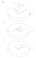
- the method for producing a phosphor adhesive sheet of the present invention includes the steps of preparing a phosphor layer containing a phosphor, plasticizing a silicone resin composition having both thermoplastic and thermosetting properties to be laminated on one surface in a thickness direction of the phosphor layer, and forming an adhesive layer by cooling the silicone resin composition to be solidified.
- the silicone resin composition having both thermoplastic and thermosetting properties is plasticized to be laminated on one surface in the thickness direction of the phosphor layer, so that the adhesive layer can be easily and uniformly formed on one surface in the thickness direction of the phosphor layer.
- the silicone resin composition is cooled to be solidified, so that the adhesive layer is formed. Therefore, the phosphor adhesive sheet including the adhesive layer can be produced with an excellent workability (handling ability).
- a light emitting diode element including a phosphor layer of the present invention includes a light emitting diode element and a phosphor adhesive sheet laminated on at least one surface in a thickness direction of the light emitting diode element, wherein the phosphor adhesive sheet includes a phosphor layer containing a phosphor and an adhesive layer laminated on one surface in the thickness direction of the phosphor layer, and the adhesive layer is formed of a silicone resin composition having both thermoplastic and thermosetting properties.
- the adhesive layer is adhered to at least one surface in the thickness direction of the light emitting diode element, so that the adhesive force of the phosphor layer with respect to the light emitting diode element is improved.
- the adhesive layer is cured by heating, the durability of the light emitting diode element including a phosphor layer can be improved.
- the reliability of the light emitting diode element including a phosphor layer can be improved.
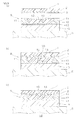
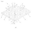
- a light emitting diode device of the present invention includes a light emitting diode package, which includes a board, a light emitting diode element mounted on the board, a reflector formed on one side in a thickness direction of the board and disposed so as to surround the light emitting diode element when projected in the thickness direction, and an encapsulating layer filled in the reflector and encapsulating the light emitting diode element; and a phosphor adhesive sheet, which is adhered to one surface in the thickness direction of the light emitting diode package, wherein the phosphor adhesive sheet includes a phosphor layer containing a phosphor and an adhesive layer laminated on one surface in the thickness direction of the phosphor layer, and the adhesive layer is formed of a silicone resin composition having both thermoplastic and thermosetting properties.
- the adhesive layer is adhered to one surface in the thickness direction of the light emitting diode package, so that the adhesive force of the phosphor layer with respect to the light emitting diode package is improved.
- the adhesive layer is formed to be thin by the plasticization, so that light emitted from the light emitting diode element can be prevented from being diffused to the outside via the adhesive layer formed on one surface in the thickness direction of the reflector. Therefore, the luminous efficiency of the light emitting diode device can be improved.
- the heat generated by wavelength conversion in the phosphor layer can be conducted to the reflector and the board via the adhesive layer formed to be thin, so that an efficient diffusion of the heat can be achieved. Therefore, the luminous efficiency of the light emitting diode device can be further improved.
- a corroding component infiltrating into the light emitting diode package can be prevented from infiltrating thereto via the adhesive layer formed to be thin.
- the adhesive layer is cured by heating, so that the durability of the light emitting diode device can be improved.
- the reliability of the light emitting diode device can be improved.
- a light emitting diode device of the present invention includes a board, a light emitting diode element mounted on the board, and a phosphor adhesive sheet adhered to at least one surface in a thickness direction of the light emitting diode element, wherein the phosphor adhesive sheet includes a phosphor layer containing a phosphor and an adhesive layer laminated on one surface in the thickness direction of the phosphor layer, and the adhesive layer is formed of a silicone resin composition having both thermoplastic and thermosetting properties.
- the adhesive layer is adhered to one surface in the thickness direction of the light emitting diode device, so that the adhesive force of the phosphor layer with respect to the light emitting diode package is improved.
- the adhesive layer is formed to be thin by the plasticization, so that the heat generated from the light emitting diode element can be efficiently conducted to the phosphor layer via the adhesive layer and therefore, the efficient diffusion of the heat can be achieved.
- the luminous efficiency of the light emitting diode device can be further improved.
- a corroding component infiltrating into the light emitting diode element can be prevented from infiltrating thereto via the adhesive layer formed to be thin.
- the adhesive layer is cured by heating, so that the durability of the light emitting diode device can be improved.
- the reliability of the light emitting diode device can be improved.
- the method for producing a light emitting diode device of the present invention includes the steps of disposing a reflector on one side in a thickness direction of a board so as to surround a light emitting diode element when projected in the thickness direction, along with mounting the light emitting diode element on the board, and thereafter, filling an encapsulating layer in the reflector so as to encapsulate the light emitting diode element to prepare a light emitting diode package; putting a phosphor adhesive sheet, which includes a phosphor layer containing a phosphor and an adhesive layer laminated on one surface in the thickness direction of the phosphor layer, on one surface in the thickness direction of the light emitting diode package such that the adhesive layer is in contact with the light emitting diode package; temporarily fixing the phosphor layer to one surface in the thickness direction of the light emitting diode package by plasticizing the adhesive layer; and adhering the phosphor layer to one surface in the thickness direction of the light emitting diode package by curing the
- the phosphor adhesive sheet is put on one surface in the thickness direction of the light emitting diode package such that the adhesive layer is in contact with the light emitting diode package and the adhesive layer is plasticized, so that the phosphor layer is temporarily fixed to one surface in the thickness direction of the light emitting diode package.
- the phosphor adhesive sheet by the plasticization of the adhesive layer, a gap can be prevented from being generated between the phosphor layer and one surface in the thickness direction of the light emitting diode package or the adhesive layer can also conform to a concavity and convexity on one surface in the thickness direction of the light emitting diode package. Therefore, by the subsequent curing by heating of the adhesive layer, the phosphor layer can be surely adhered to the light emitting diode package.
- the phosphor layer can be peeled off from the light emitting diode package judged as defective to be temporarily fixed (reworked) to another light emitting diode package.
- the yield rate of the phosphor layer can be improved to reduce the production cost.
- the phosphor layer is adhered to the light emitting diode package by curing the adhesive layer by heating, so that the adhesive force of the phosphor layer with respect to the light emitting diode package can be improved.
- the method for producing a light emitting diode device of the present invention includes the steps of putting a phosphor adhesive sheet, which includes a phosphor layer containing a phosphor and an adhesive layer laminated on one surface in a thickness direction of the phosphor layer, on at least one surface in the thickness direction of a light emitting diode element such that the adhesive layer is in contact with the light emitting diode element; temporarily fixing the phosphor layer to at least one surface in the thickness direction of the light emitting diode element by plasticizing the adhesive layer; and adhering the phosphor layer to at least one surface in the thickness direction of the light emitting diode element by curing the adhesive layer by heating, wherein the adhesive layer is formed of a silicone resin composition having both thermoplastic and thermosetting properties.
- the phosphor adhesive sheet is put on at least one surface in the thickness direction of the light emitting diode element such that the adhesive layer is in contact with the light emitting diode element and the adhesive layer is plasticized, so that the phosphor layer is temporarily fixed to at least one surface in the thickness direction of the light emitting diode element.
- the phosphor adhesive sheet by the plasticization of the adhesive layer, a gap can be prevented from being generated between the phosphor layer and one surface in the thickness direction of the light emitting diode element or the adhesive layer can also conform to a concavity and convexity on at least one surface in the thickness direction of the light emitting diode element. Therefore, by the subsequent curing by heating of the adhesive layer, the phosphor layer can be surely adhered to the light emitting diode element.
- the phosphor layer can be peeled off from the light emitting diode element judged as defective by heating to be temporarily fixed (reworked) to another light emitting diode element.
- the yield rate of the phosphor layer can be improved to reduce the production cost.
- the phosphor layer is adhered to the light emitting diode element by curing the adhesive layer by heating, so that the adhesive force of the phosphor layer with respect to the light emitting diode element can be improved.
- a step of mounting the light emitting diode element on the board is further included and the putting step is performed after the mounting step.
- a step of mounting the light emitting diode element on the board is further included and the mounting step is performed after the adhering step.
- the method for producing a light emitting diode element including a phosphor layer includes the steps of putting a phosphor adhesive sheet, which includes a phosphor layer containing a phosphor and an adhesive layer laminated on one surface in a thickness direction of the phosphor layer, on at least one surface in the thickness direction of a light emitting diode element such that the adhesive layer is in contact with the light emitting diode element; temporarily fixing the phosphor layer to at least one surface in the thickness direction of the light emitting diode element by plasticizing the adhesive layer; and adhering the phosphor layer to at least one surface in the thickness direction of the light emitting diode element by curing the adhesive layer by heating, wherein the adhesive layer is formed of a silicone resin composition having both thermoplastic and thermosetting properties.
- the phosphor adhesive sheet is put on at least one surface in the thickness direction of the light emitting diode element such that the adhesive layer is in contact with the light emitting diode element and the adhesive layer is plasticized, so that the phosphor layer is temporarily fixed to at least one surface in the thickness direction of the light emitting diode element.
- a gap can be prevented from being generated between the phosphor layer and at least one surface in the thickness direction of the light emitting diode element or the adhesive layer can also conform to a concavity and convexity on at least one surface in the thickness direction of the light emitting diode element. Therefore, by the subsequent curing by heating of the adhesive layer, the phosphor layer can be surely adhered to the light emitting diode element.
- the phosphor layer is adhered to the light emitting diode element by curing the adhesive layer by heating, so that the adhesive force of the phosphor layer with respect to the light emitting diode element can be improved.
- the adhesive force of the phosphor layer with respect to the light emitting diode element is improved by the adhesive layer, so that the light emitting diode element including a phosphor layer which has an excellent durability and improved reliability can be produced.
- the adhesive layer is plasticized by heating, so that the phosphor layer can be temporarily fixed to the object, and by the subsequent heating, the adhesive layer is cured by heating, so that the phosphor layer can be adhered to the object.
- the adhesive layer can be easily and uniformly formed on one surface in the thickness direction of the phosphor layer, so that the phosphor adhesive sheet and the light emitting diode element including a phosphor layer can be produced with an excellent workability (handling ability).
- the adhesive force of the phosphor layer with respect to the light emitting diode package or the light emitting diode element is improved, so that the light emitting diode device and the light emitting diode element including a phosphor layer can have an excellent durability and the reliability thereof can be improved.
- the production cost can be reduced.
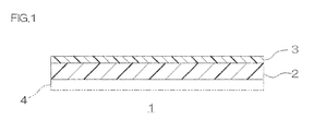
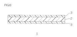
- FIG. 1 shows a sectional view of one embodiment of a phosphor adhesive sheet of the present invention.
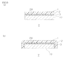
- FIG. 2 shows perspective views for illustrating one embodiment of a method for producing the phosphor adhesive sheet of the present invention.
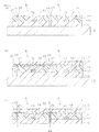
- FIG. 3 shows sectional views for illustrating one embodiment of a method for producing a light emitting diode device of the present invention.
- a phosphor adhesive sheet 1 includes a phosphor layer 2 and an adhesive layer 3 laminated on the upper surface (one surface in a thickness direction) of the phosphor layer 2.
- the phosphor layer 2 is a wavelength conversion layer, which converts a part of blue light emitted from a light emitting diode element 10 to be described later (ref: FIG. 3 ) to yellow light and allows the remaining blue light to transmit therethrough.
- the phosphor layer 2 is formed into a plate shape or a sheet shape.
- the phosphor layer 2 is formed of, for example, a ceramic of a phosphor as a phosphor ceramic plate or is formed of a phosphor resin composition containing a phosphor and a resin as a phosphor resin sheet.
- the phosphor emits fluorescent light, which is excited by absorbing a part or all of the light whose wavelength is in the range of 350 to 480 nm as an exciting light and has a wavelength longer than that of the exciting light, for example, in the range of 500 to 650 nm.
- an example of the phosphor includes a yellow phosphor.
- An example thereof includes a phosphor obtained by doping a metal atom such as cerium (Ce) or europium (Eu) into a composite metal oxide, a metal sulfide, or the like.
- examples of the phosphor include a garnet type phosphor having a garnet type crystal structure such as Y 3 Al 5 O 12 :Ce (YAG (yttrium aluminum gamet):Ce), (Y, Gd) 3 Al 5 O 12 :Ce, Tb 3 Al 3 O 12 :Ce, Ca 3 Sc 2 Si 3 O 12 :Ce, and Lu 2 CaMg 2 (Si, Ge) 3 O 12 :Ce; a silicate phosphor such as (Sr, Ba) 2 SiO 4 :Eu, Ca 3 SiO 4 Cl 2 :Eu, Sr 3 SiO 5 :Eu, Li 2 SrSiO 4 :Eu, and Ca 3 Si 2 O 7 :Eu; an aluminate phosphor such as CaAl 12 O 19 :Mn and SrAl 2 O 4 :Eu; a sulfide phosphor such as ZnS:Cu,Al, CaS:Eu, CaGa 2
- the phosphors can be used alone or in combination of two or more.
- the above-described phosphor is used as a ceramic material and by sintering the ceramic material, the phosphor layer 2 (phosphor ceramic) is obtained.
- An additive can be added to the ceramic material at an appropriate ratio.
- examples thereof include a binder resin, a dispersant, a plasticizer, and a sintering additive.
- the above-described phosphor is blended with the resin, so that the phosphor resin composition is prepared.
- the resin is a matrix in which the phosphor is dispersed, including, for example, a transparent resin such as a silicone resin composition, an epoxy resin, and an acrylic resin.
- a transparent resin such as a silicone resin composition, an epoxy resin, and an acrylic resin.
- a silicone resin composition is used.
- the silicone resin composition has, in its molecule, a main chain mainly composed of the siloxane bond (-Si-O-Si-) and a side chain, which is bonded to silicon atoms (Si) of the main chain, and composed of an organic group such as an alkyl group (for example, a methyl group and the like) or an alkoxyl group (for example, a methoxy group).
- a main chain mainly composed of the siloxane bond (-Si-O-Si-) and a side chain, which is bonded to silicon atoms (Si) of the main chain, and composed of an organic group such as an alkyl group (for example, a methyl group and the like) or an alkoxyl group (for example, a methoxy group).
- examples of the silicone resin composition include a dehydration condensation type silicone resin, an addition reaction type silicone resin, a peroxide curable silicone resin, a moisture curable silicone resin, and a curable silicone resin.
- an addition reaction type silicone resin is used.
- the silicone resin composition has a kinetic viscosity at 25°C in the range of, for example, 10 to 30 mm 2 /s.
- the resins can be used alone or in combination of two or more.
- the mixing ratio of each of the components is as follows.
- the mixing ratio of the phosphor is, for example, 1 to 50 mass %, or preferably 5 to 30 mass % with respect to the phosphor resin composition.
- the mixing ratio of the phosphor is, for example, 1 to 100 parts by mass, or preferably 5 to 40 parts by mass with respect to 100 parts by mass of the resin.
- the mixing ratio of the resin is, for example, 50 to 99 mass %, or preferably 70 to 95 mass % with respect to the phosphor resin composition.
- the phosphor and the resin are blended at the above-described mixing ratio to be stirred and mixed, so that the phosphor resin composition is prepared.
- the prepared phosphor resin composition is molded into a sheet shape and to be specific, is formed as a phosphor resin sheet.
- the phosphor layer 2 has a thickness of, for example, 100 to 1000 ⁇ m when formed as a phosphor ceramic plate.
- the phosphor layer 2 has a thickness of, in view of film formability and appearance of device, for example, 25 to 1000 ⁇ m, or preferably 50 to 200 ⁇ m when formed of a phosphor resin sheet.
- the adhesive layer 3 is formed on the entire upper surface (one surface in the thickness direction) of the phosphor layer 2.
- the adhesive layer 3 is formed of a silicone resin composition having both thermoplastic and thermosetting properties.
- silicone resin composition examples include a first silicone resin composition, a second silicone resin composition, a third silicone resin composition, a fourth silicone resin composition, a fifth silicone resin composition, and a sixth silicone resin composition.
- the first silicone resin composition contains, for example, a silicone resin composition containing amino groups at both ends, a diisocyanate, and a radical generator.
- the silicone resin composition containing amino groups at both ends is, preferably, in view of transparency and high heat resistance, a compound represented by the following formula (1).
- R 1 represents a monovalent hydrocarbon group
- R 2 represents an alkenyl group
- R 3 represents an alkylene group.
- "a” represents an integer of 0 or 1 or more
- "b” represents an integer of 0 or 1 or more.
- "a+b" safisfies the relationship of being an integer of at least 1 or more. All of the R 1 s may be the same or different from each other and "b" pieces of R 2 may be the same or different from each other.
- the compound represented by formula (1) consists of the constituent units A, B, C, and D and is a compound containing an amino group (-NH 2 ) in its end unit.
- the hydrocarbon group represented by R 1 in formula (1) is, for example, a saturated hydrocarbon group or an aromatic hydrocarbon group.
- the number of carbon atoms in the hydrocarbon group is, in view of availability, for example, 1 to 20, or preferably 1 to 10.
- An example of the saturated hydrocarbon group includes an alkyl group such as methyl, ethyl, propyl, butyl, pentyl, hexyl, cyclohexyl, and cyclopentyl.
- An example of the aromatic hydrocarbon group includes an aryl group such as phenyl, benzyl, and tolyl.
- hydrocarbon groups represented by R 1 in view of transparency and light resistance of the obtained first silicone resin composition, preferably, methyl and phenyl are used, or more preferably, methyl is used.
- R 1 s are independent respectively, regardless of the constituent unit, and represent the above-described hydrocarbon group.
- R 2 in formula (1) examples include a substituted or unsubstituted alkenyl group.
- an organic group containing an alkenyl group in the skeleton is used.
- examples thereof include vinyl, allyl, butynyl, pentynyl, and hexynyl.
- vinyl is used.
- R 3 in formula (1) examples include a substituted or unsubstituted alkylene group.
- an organic group containing an alkylene group in the skeleton is used.
- the number of carbon atoms in the organic group is, in view of transparency and heat resistance of the obtained first silicone resin composition, for example, 1 to 10.
- examples thereof include methylene, ethylene, propylene, butylene, pentylene, hexylene, and heptylene.
- propylene is used.
- all of the R 3 s that is, two R 3 s may be the same or different from each other.
- the constituent unit A is an end unit and to be specific, is contained in one end of a molecule. That is, one constituent unit A is contained in formula (1).
- the constituent unit D is an end unit and to be specific, is contained in the other end of the molecule, which is the opposite side of the constituent unit A. That is, one constituent unit D is contained in formula (1).
- the repeating unit number of the constituent unit B, that is, "a" in formula (1) represents an integer of 0 or 1 or more and is, in view of transparency of the obtained first silicone resin composition, for example, an integer of 1 to 10000, or preferably an integer of 10 to 10000.
- the repeating unit number of the constituent unit C is, in view of transparency of the obtained first silicone resin composition, for example, an integer of 0 to 10000, or preferably an integer of 0 to 1000.
- the sum of "a” and “b” is preferably 1 to 10000, or more preferably 10 to 10000.
- the sum of “a” and “b” is an integer of at least 1 or more and therefore, either “a” or “b” may be 0.
- a commercially available product can be used as the silicone resin composition containing amino groups at both ends represented by formula (1).
- the silicone resin composition containing amino groups at both ends can be also synthesized in accordance with a known method.
- the weight average molecular weight of the silicone resin composition containing amino groups at both ends represented by formula (1) is, in view of stability and handling ability, for example, 100 to 1000000, or preferably 1000 to 100000.
- the weight average molecular weight is measured with a gel permeation chromatography (GPC: calibrated with standard polystyrene equivalent) and the same applies hereinafter.
- the content of the silicone resin composition containing amino groups at both ends in the first silicone resin composition is, for example, 1 to 99.9 mass %, or preferably 80 to 99.9 mass %.
- the diisocyanate is, in view of compatibility with each of the components, for example, represented by the following formula (2).
- Y represents a divalent hydrocarbon group.
- Y in formula (2) include a saturated or unsaturated straight chain, branched chain, or cyclic hydrocarbon group.
- the number of carbon atoms in the hydrocarbon group is, in view of availability and heat resistance of the obtained first silicone resin composition, for example, 1 to 50, or preferably 1 to 30.
- the diisocyanate include aliphatic diisocyanate, aromatic diisocyanate, alicyclic diisocyanate, or modified forms thereof.
- examples of the diisocyanate include hexamethylene diisocyanate, 4,4'-methylene dicyclohexylene diisocyanate, 4,4'-methylene diphenylene diisocyanate, 1,3-diazetidine-2,4-dione-bis(4,4'-methylene dicyclohexyl)diisocyanate, 1,3-diazetidine-2,4-dione-bis(4,4-methylene diphenyl)diisocyanate, tetramethylene xylylene diisocyanate, isophorone diisocyanate, tolylene2,4-diisocyanate, and dicyclohexylmethylene diisocyanate.
- tolylene2,4-diisocyanate preferably, isophorone diisocyanate, and hexamethylene diisocyanate are used.
- a commercially available product can be used as the diisocyanate.
- the diisocyanate can be also synthesized in accordance with a known method.
- the content of the diisocyanate in the first silicone resin composition is, for example, 1.0 ⁇ 10 -5 to 20 mass %, or preferably 1.0 ⁇ 10 -5 to 10 mass %.
- the molar ratio (the amino group/the isocyanate group) of the functional groups is, for example, 0.1/1 to 1/0.1, or preferably substantially equal in amount (1/1).
- the radical generator is a compound, which generates radical and accelerates a cross-linking reaction among the silicone resin compositions containing amino groups at both ends.
- examples thereof include a photo radical generator and an organic peroxide.
- the first silicone resin composition shows thermoplastic properties/thermosetting properties according to the temperature. Therefore, preferably, an organic peroxide, which generates radical by heating, is used.
- examples of the radical generator include methyl ethyl ketone peroxide, cyclohexanone peroxide, methylcyclohexanone peroxide, acetylacetone peroxide, 1,1-di(t-hexylperoxy)-3,3,5-trimethylcyclohexane, 1,1-di(t-hexylperoxy)cyclohexane, 1,1-di(t-butylperoxy)-2-methylcyclohexane, 1,1-di(t-butylperoxy)cyclohexane, 2,2-di(t-butylperoxy)butane, 2,2-di(4,4-di-(butylperoxy)cyclohexyl)propane, p-menthane hydroperoxide, diisopropylbenzene hydroperoxide, 1,1,3,3-tetramethylbutyl hydroperoxide, cumene hydroperoxide, t-butyl
- di-t-butyl peroxide 2,5-dimethyl-2,5-di(t-butylperoxy)hexane, and t-butyl peroxybenzene are used.
- the temperature at which these radical generators generate radical is not unconditionally determined and is, for example, 100°C or more.
- the radical generator can be also synthesized in accordance with a known method.
- the content of the radical generator in the first silicone resin composition is, for example, 1.0 ⁇ 10 -6 to 20 mass %, or preferably 1.0 ⁇ 10 -6 to 10 mass %.
- the content of the radical generator with respect to 100 mol % of R 1 group amount in the silicone resin composition containing amino groups at both ends is, in view of maintaining flexibility of the obtained first silicone resin composition, for example, 0.001 to 50 mol %, or preferably 0.01 to 10 mol %.
- the first silicone resin composition can be prepared without any particular limitation as long as it contains the silicone resin composition containing amino groups at both ends, the diisocyanate, and the radical generator.
- reaction temperature and duration are appropriately selected according to the respective reaction mechanism of the reaction of the isocyanate group and the cross-linking reaction by the radical generator to proceed and terminate the reactions.
- components related to the reaction of the isocyanate group that is, the silicone resin composition containing amino groups at both ends and the diisocyanate are mixed in advance and then, the radical generator is blended thereto.
- the mixing of the components related to the reaction of the isocyanate group is performed by stirring the silicone resin composition containing amino groups at both ends and the diisocyanate, and an additive such as an organic solvent as required at, for example, 0 to 100°C, or preferably 10 to 60°C for, for example, 0.1 to 40 hours.
- the organic solvent is not particularly limited and in view of improving compatibility of each of the components, preferably, ketone such as methyl ethyl ketone is used.
- a part of the reaction of the amino group in the silicone resin composition containing amino groups at both ends with the isocyanate group in the diisocyanate may start.
- the degree of progress of the reaction can be checked by 1 H-NMR measurement based on the degree of disappearance of the peak derived from the amino group.
- the radical generator is mixed in a mixture of the components related to the reaction of the isocyanate group described above.
- a cured product (a molded product) can be obtained by the occurrence of the cross-linking reaction on obtaining the cured product by performing two types of the reactions, that is, the reaction of the isocynate group and the cross-linking reaction by the radical generator. Therefore, the mixing method is not particularly limited as long as the radical generator is uniformly mixed into the mixture of the components related to the reaction of the isocyanate group described above.
- the radical generator is blended into the mixture of the silicone resin composition containing amino groups at both ends and the diisocyanate to be stirred and mixed.
- the mixing duration is not unconditionally determined according to the reaction temperature and the type and amount of the component subjected to the reaction and is, for example, 0.1 to 40 hours.
- a solvent or the like can be removed in accordance with a known method.
- the first silicone resin composition obtained in this way is solid under normal temperature, shows a thermoplastic behavior at 40°C or more, and furthermore, shows thermosetting properties at 50°C or more.
- the thermoplastic temperature of the first silicone resin composition is preferably 40 to 200°C, or more preferably 80 to 150°C.
- the thermoplastic temperature is the temperature at which the first silicone resin composition shows thermoplastic properties.
- the thermoplastic temperature is the temperature at which the first silicone resin composition in a solid state is softened by heating to be brought into a completely liquid state and is substantially the same as the softening temperature.
- the thermosetting temperature of the first silicone resin composition is preferably 100 to 200°C, or more preferably 130 to 200°C.
- the thermosetting temperature is the temperature at which the first silicone resin composition shows thermosetting properties.
- the thermosetting temperature is the temperature at which the first silicone resin composition in a liquid state is cured by heating to be brought into a completely solid state.
- the second silicone resin composition contains, for example, a silicone resin composition containing amino groups at both ends, an organohydrogenpolysiloxane, a diisocyanate, and a hydrosilylation catalyst.
- An example of the silicone resin composition containing amino groups at both ends in the second silicone resin composition includes the same silicone resin composition containing amino groups at both ends as that illustrated in the first silicone resin composition.
- the content of the silicone resin composition containing amino groups at both ends in the second silicone resin composition is, for example, 1 to 99.5 mass %, or preferably 80 to 99.5 mass %.
- the organohydrogenpolysiloxane is a polysiloxane containing a hydrosilyl group (-SiH).
- the organohydrogenpolysiloxane is in a straight chain and an example thereof includes a side-chain type organohydrogenpolysiloxane, which contains a hydrosilyl group in its side chain bonded to the main chain, and/or a dual-end type organohydrogenpolysiloxane, which contains hydrosilyl groups at both ends of a molecule.
- the side-chain type organohydrogenpolysiloxane is, for example, represented by the following formula (3).
- R 4 represents a monovalent hydrocarbon group.
- "e” represents an integer of 0 or 1 or more and "f” represents an integer of 1 or more.
- E to H constitute the side-chain type organohydrogenpolysiloxane.
- the monovalent hydrocarbon group represented by R 4 in formula (3) may be the same or different from each other. Preferably, the monovalent hydrocarbon group represented by R 4 is the same.
- An example of the monovalent hydrocarbon group represented by R 4 includes the same monovalent hydrocarbon group as that represented by R 1 in the above-described formulas (1) and (2).
- methyl and phenyl are used, or more preferably, methyl is used.
- e represents, in view of reactivity and stability, preferably an integer of 1 to 10000, or more preferably an integer of 1 to 5000.
- f represents preferably an integer of 2 or more, and also represents, in view of reactivity and stability, preferably an integer of 1 to 10000, more preferably an integer of 1 to 1000, in view of imparting flexibility to the silicone resin composition while obtaining it in a solid state at room temperature, particularly preferably an integer larger than "e", or most preferably an integer of 100 to 1000.
- Examples of the side-chain type organohydrogenpolysiloxane include methylhydrogensiloxane, dimethylsiloxane-co-methylhydrogensiloxane, ethylhydrogensiloxane, and methylhydrogensiloxane-co-methylphenylsiloxane.
- the number average molecular weight of the side-chain type organohydrogenpolysiloxane is, in view of stability and handling ability, for example, 200 to 100000, or preferably 200 to 80000.
- the side-chain type organohydrogenpolysiloxane can be, for example, synthesized in accordance with a known method.
- a commercially available product for example, manufactured by Gelest, Inc., and Shin-Etsu Chemical Co., Ltd. can also be used.
- the dual-end type organohydrogenpolysiloxane is, for example, represented by the following formula (4).
- R to U represent a constituent unit
- R and U represent an end unit
- S and T represent a repeating unit
- R 5 represents a monovalent hydrocarbon group selected from a saturated hydrocarbon group and an aromatic hydrocarbon group.
- "g” represents an integer of 0 or more and "t” represents an integer of 0 or more.
- R to U constitute the dual-end type organohydrogenpolysiloxane.
- the monovalent hydrocarbon group represented by R 5 in formula (4) may be the same or different from each other.
- the monovalent hydrocarbon group represented by R 5 is the same.
- An example of the monovalent hydrocarbon group represented by R 5 includes the same monovalent hydrocarbon group as that represented by R 1 in the above-described formula (1).
- As the monovalent hydrocarbon group represented by R 5 preferably, a methyl group and a phenyl group are used, or more preferably, a methyl group is used.
- g represents, in view of reactivity and stability, preferably an integer of 0 or more, more preferably an integer of 1 to 10000, or particularly preferably an integer of 1 to 5000.
- t represents, in view of reactivity and stability, preferably an integer of 0 or more, more preferably an integer of 1 to 10000, or particularly preferably an integer of 1 to 5000.
- the dual-end type organohydrogenpolysiloxane is, for example, when "t" is 1 or more, an organopolysiloxane containing both a hydrogen atom in its side chain and hydrogen atoms at both ends, which contains a hydrogen atom in the side chain branched off from the main chain and hydrogen atoms at both ends of the main chain.
- examples thereof include methylhydrogenpolysiloxane containing hydrosilyl groups at both ends, (dimethylpolysiloxane-co-methylhydrogenpolysiloxane) containing hydrosilyl groups at both ends, ethylhydrogenpolysiloxane containing hydrosilyl groups at both ends, and (methylhydrogenpolysiloxane-co-methylphenylpolysiloxane) containing hydrosilyl groups at both ends.
- the dual-end type organohydrogenpolysiloxane is, for example, when "t" is 0, an organopolysiloxane containing no hydrogen atom in its side chain/containing hydrogen atoms at both ends, which does not contain a hydrogen atom in the side chain branched off from the main chain and contains hydrogen atoms at both ends of the main chain.
- examples thereof include polydimethylsiloxane containing hydrosilyl groups at both ends, polymethylphenylsiloxane containing hydrosilyl groups at both ends, and polydiphenylsiloxane containing hydrosilyl groups at both ends.
- an organopolysiloxane containing no hydrogen atom in its side chain/containing hydrogen atoms at both ends represented by formula (5) is used.
- R 5 represents a monovalent hydrocarbon group selected from a saturated hydrocarbon group and an aromatic hydrocarbon group.
- g represents an integer of 1 or more.
- the monovalent hydrocarbon group represented by R 5 in formula (5) may be the same or different from each other.
- the monovalent hydrocarbon group represented by R 5 is the same.
- R 5 is the same as the description above and "g" is the same as the description above.
- the number average molecular weight of the dual-end type organohydrogenpolysiloxane is, in view of stability and handling ability, for example, 100 to 30000, or preferably 100 to 10000.
- the dual-end type organohydrogenpolysiloxane can be, for example, synthesized in accordance with a known method. A commercially available product can also be used.
- the content of the hydrosilyl group in the organohydrogenpolysiloxane is, for example, 0.01 to 20 mmol/g, or preferably 0.05 to 15 mmol/g.
- the content of the hydrosilyl group is calculated from the integral value of the hydrosilyl group and the methyl group with a 1 H-NMR.
- the organohydrogenpolysiloxane can be, for example, synthesized in accordance with a known method.
- a commercially available product for example, manufactured by Gelest, Inc., and Shin-Etsu Chemical Co., Ltd. can also be used.
- the content of the organohydrogenpolysiloxane in the second silicone resin composition is, for example, 0.0001 to 90 mass %, or preferably 0.001 to 50 mass %.
- the molar ratio (the alkenyl group/the SiH group) of the functional groups is, for example, 1/1 to 0.1/1, preferably 1/1 to 0.2/1, more preferably 1/1 to 0.5/1, or particularly preferably substantially equal in amount (1/1).
- An example of the diisocyanate includes the same diisocyanate as that illustrated in the first silicone resin composition.
- the content of the diisocyanate in the second silicone resin composition is, for example, 1.0 ⁇ 10 -5 to 20 mass %, or preferably 1.0 ⁇ 10 -5 to 10 mass %.
- the molar ratio (the amino group/the isocyanate group) of the functional groups is, for example, 1/1 to 0.1/1, preferably 1/1 to 0.2/1, more preferably 1/1 to 0.5/1, or particularly preferably substantially equal in amount (1/1).
- the hydrosilylation catalyst is not particularly limited as long as it is a compound, which catalyzes the hydrosilylation reaction of the alkenyl group in the silicone resin composition containing amino groups at both ends with the hydrosilyl group in the organohydrogenpolysiloxane.
- the hydrosilylation catalyst include a platinum catalyst such as platinum black, platinum chloride, chloroplatinic acid, a platinum olefin complex, a platinum carbonyl complex, and platinum acetyl acetate; a palladium catalyst; and a rhodium catalyst.
- the content of the hydrosilylation catalyst in the second silicone resin composition for example, when the platinum catalyst is used, in view of reaction speed, the content of the platinum is, for example, 1.0 ⁇ 10 -10 to 0.5 parts by mass, or preferably 1.0 ⁇ 10 -8 to 1.0 ⁇ 10 -3 parts by mass with respect to 100 parts by mass of the organohydrogenpolysiloxane.
- the second silicone resin composition can be prepared without any particular limitation as long as it contains each of the components of the silicone resin composition containing amino groups at both ends, the organohydrogenpolysiloxane, the diisocyanate, and the hydrosilylation catalyst.
- reaction temperature and duration are appropriately selected according to the respective reaction mechanism of the reaction of the isocyanate group and the hydrosilylation reaction to proceed and terminate the reactions.
- components related to the reaction of the isocyanate group are mixed in advance and then, the components related to the hydrosilylation reaction may be mixed thereto.
- the mixing of the components related to the reaction of the isocyanate group can be performed by stirring the silicone resin composition containing amino groups at both ends and the diisocyanate, and an additive such as an organic solvent as required at, for example, 0 to 100°C, or preferably 10 to 60°C for, for example, 0.1 to 40 hours.
- the organic solvent is not particularly limited and in view of improving compatibility of each of the components, preferably, ketone such as methyl ethyl ketone is used.
- a part of the reaction of the amino group in the silicone resin composition containing amino groups at both ends with the isocyanate group in the diisocyanate may start.
- the degree of progress of the reaction can be checked by 1 H-NMR measurement based on the degree of disappearance of the peak derived from the amino group.
- the organohydrogenpolysiloxane and the hydrosilylation catalyst are blended in a mixture of the components related to the reaction of the isocyanate group described above.
- the mixing method is not particularly limited as long as the components related to the hydrosilylation reaction are uniformly mixed into the mixture of the components related to the reaction of the isocyanate group described above.
- the organohydrogenpolysiloxane and the hydrosilylation catalyst are blended into the mixture of the silicone resin composition containing amino groups at both ends and the diisocyanate to be stirred and mixed.
- the mixing duration is not unconditionally determined according to the reaction temperature and the type and amount of the component subjected to the reaction and is, for example, 0.1 to 40 hours.
- the mixing method is not particularly limited as long as each of the components is uniformly mixed.
- a solvent or the like can be removed in accordance with a known method.
- the second silicone resin composition obtained in this way is solid under normal temperature, shows a thermoplastic behavior at 40°C or more, and furthermore, shows thermosetting properties at 50°C or more.
- thermoplastic temperature of the second silicone resin composition is, for example, 40 to 200°C, or preferably 40 to 150°C.
- thermosetting temperature in the second silicone resin composition, the hydrosilylation reaction proceeds and the second silicone resin composition is cured by heating.
- the thermosetting temperature is, for example, 100 to 200°C, or preferably 130 to 200°C.
- the degree of progress of the hydrosilylation reaction can be checked by 1 H-NMR measurement based on the intensity of a signal derived from the amino group in the silicone resin composition containing amino groups at both ends. The reaction is considered to be terminated at the time of disappearance of the signal.
- the third silicone resin composition is obtained by allowing a cage octasilsesquioxane to react with an alkenyl group-containing polysiloxane in the presence of a hydrosilylation catalyst.
- the cage octasilsesquioxane is an octamer of trifunctional silicone monomer and to be specific, has eight groups represented by the following formula (6),
- R 6 represents a monovalent hydrocarbon group
- R 7 represents hydrogen or a monovalent hydrocarbon group.
- the molar ratio of the monovalent hydrocarbon group: hydrogen in R 7 in the cage octasilsesquioxane as a whole is, as an average value, in the range of 6.5:1.5 to 5.5:2.5.
- the cage octasilsesquioxane is represented by the following formula (7).
- R 6 and R 7 are the same as the description above.
- the molar ratio of the monovalent hydrocarbon group: hydrogen in R 7 is the same as the description above.
- An example of the monovalent hydrocarbon group represented by R 6 in the above-described formulas (6) and (7) includes a saturated hydrocarbon group or an aromatic hydrocarbon group.
- saturated hydrocarbon group examples include a straight chain saturated hydrocarbon group (for example, an alkyl group having 1 to 6 carbon atoms such as methyl, ethyl, propyl, butyl, pentyl, and hexyl), a branched chain saturated hydrocarbon group (for example, an alkyl group having 3 to 6 carbon atoms such as isopropyl and isobutyl), and a cyclic saturated hydrocarbon group (for example, a cycloalkyl group having 3 to 6 carbon atoms such as cyclohexyl).
- a straight chain saturated hydrocarbon group for example, an alkyl group having 1 to 6 carbon atoms such as methyl, ethyl, propyl, butyl, pentyl, and hexyl
- branched chain saturated hydrocarbon group for example, an alkyl group having 3 to 6 carbon atoms such as isopropyl and isobutyl
- a cyclic saturated hydrocarbon group for example,
- aromatic hydrocarbon group includes an aryl group having 6 to 8 carbon atoms such as phenyl, benzyl, and tolyl.
- the number of carbon atoms of the monovalent hydrocarbon group is, for example, 1 to 8, or preferably 1 to 6.
- R 6 may be the same or different from each other. Preferably, R 6 is the same.
- a saturated and straight chain hydrocarbon group is used, more preferably, an alkyl group having 1 to 6 carbon atoms is used, or particularly preferably, methyl is used.
- An example of the monovalent hydrocarbon group represented by R 7 in the above-described formulas (6) and (7) includes the same monovalent hydrocarbon group as that represented by R 1 described above.
- the molar ratio of the monovalent hydrocarbon group: hydrogen in R 7 in formula (7), the cage octasilsesquioxane as a whole, is in the range of 6.5:1.5 to 5.5:2.5, or preferably 6.0:2.0 to 5.5:2.5 as an average value.
- the group represented by the above-described formula (6) forms 1.5 to 2.5 (to be specific, two), or preferably 2 to 2.5 (to be specific, two) of the hydrosilyl groups (-SiH).
- the third silicone resin composition may not show thermoplastic properties.
- examples of the above-described cage octasilsesquioxane include a cage octasilsesquioxane having methyl in R 6 and methyl or hydrogen in R 7 in the above-described formulas (6) and (7) and having a molar ratio of methyl: hydrogen in R 7 in the cage octasilsesquioxane as a whole of 5.5:2.5, 6:2, or 6.5:1.5 as an average value.
- the cage octasilsesquioxane represented by the above-described formula (7) is, for example, synthesized in accordance with a known method (for example, in accordance with the description in Japanese Unexamined Patent Publication No. 2007-246880 ).
- tetraalkoxysilane (tetraethoxysilane and the like) is allowed to react with an alcohol such as methanol and/or with water in the presence of a catalyst to synthesize an octa (silsesquioxane) skeleton (a portion in formula (7) excluding the groups of formula (6)) and thereafter, dialkylchlorosilane (dimethylchlorosilane and the like) and trialkylchlorosilane (trimethylchlorosilane and the like) are blended at a mixing ratio corresponding to the molar ratio of the monovalent hydrocarbon group: hydrogen in the above-described R 7 .
- an alkoxyl group (ethoxy and the like) bonded to the silicon atom of the octa (silsesquioxane) skeleton is allowed to react with dialkylchlorosilane and trialkylchlorosilane. After the reaction, the reactant is refined as required. In this way, the cage octasilsesquioxane can be obtained.
- a commercially available product can also be used as the cage octasilsesquioxane.
- the alkenyl group-containing polysiloxane is a polysiloxane containing alkenyl groups at both ends, which contains alkenyl groups at both ends of the molecule.
- alkenyl group-containing polysiloxane is represented by the following formula (8).
- R 8 represents a monovalent hydrocarbon group and R 9 represents an alkenyl group.
- "i" represents an integer of 1 or more.
- the monovalent hydrocarbon group represented by R 8 in formula (8) may be the same or different from each other.
- the monovalent hydrocarbon group represented by R 8 is the same.
- R 8 An example of the monovalent hydrocarbon group represented by R 8 includes the same monovalent hydrocarbon group as that represented by R 6 in the above-described formulas (6) and (7).
- methyl and phenyl are used, or more preferably, methyl is used.
- Examples of the alkenyl group represented by R 9 in formula (8) include a substituted or unsubstituted alkenyl group. Preferably, an unsubstituted alkenyl group is used.
- alkenyl group includes an alkenyl group having 2 to 10 carbon atoms such as vinyl, allyl, propenyl, butenyl, and pentenyl.
- the number of carbon atoms of the alkenyl group is, for example, 2 to 10, or preferably 2 to 5.
- R 9 may be the same or different from each other. Preferably, R 9 is the same.
- alkenyl group preferably, in view of reactivity with the hydrosilyl group in the cage octasilsesquioxane, an alkenyl group having 2 to 5 carbon atoms is used, or more preferably, vinyl is used.
- i represents, in view of reactivity and stability, preferably an integer of 1 to 5000, or more preferably an integer of 1 to 1000.
- the number average molecular weight of the alkenyl group-containing polysiloxane represented by the above-described formula (8) is, in view of safety and handling ability, for example, 100 to 10000, or preferably 300 to 5000.
- the alkenyl group-containing polysiloxane represented by the above-described formula (8) can be, for example, synthesized in accordance with a known method.
- a commercially available product for example, manufactured by Gelest, Inc.
- Gelest, Inc. can also be used.
- hydrosilylation catalyst includes the same hydrosilylation catalyst as that illustrated in the second silicone resin composition.
- a platinum catalyst is used, or more preferably, a platinum olefin complex is used.
- a platinum-divinylsiloxane complex such as a platinum-1,3-diviny-1,1,3,3-tetramethyldisiloxane complex is used.
- the hydrosilylation catalyst may be prepared as a solution in a known solvent (such as toluene).
- the mixing ratio of the hydrosilylation catalyst is, for example, 1.0 ⁇ 10 -10 to 3 parts by mass, or preferably 1.0 ⁇ 10 -8 to 1 parts by mass with respect to 100 parts by mass of the total amount of the cage octasilsesquioxane and the alkenyl group-containing polysiloxane.
- the cage octasilsesquioxane is allowed to react with the alkenyl group-containing polysiloxane in the presence of the hydrosilylation catalyst such that the number of moles of the hydrosilyl group in the cage octasilsesquioxane is larger (excessive) than that of the alkenyl group in the alkenyl group-containing polysiloxane.
- the molar ratio (the number of moles of the alkenyl group/the number of moles of the hydrosilyl group) of the alkenyl group to the hydrosilyl group is below 1, for example, 0.10 to 0.99, preferably 0.20 to 0.99, or more preferably 0.50 to 0.99.
- the hydrosilyl group is fewer than the alkenyl group. In such a case, the excess of the hydrosilyl group does not remain after the reaction and thermosetting properties may not be imparted to the third silicone resin composition.
- the solvent examples include an aromatic hydrocarbon such as toluene, an aliphatic hydrocarbon such as hexane, and ester such as ethyl acetate.
- an aromatic hydrocarbon is used, or more preferably, toluene is used.
- the reaction temperature is, for example, 0 to 100°C, or preferably 20 to 80°C and the reaction duration is, for example, 0.5 to 96 hours.
- the degree of the hydrosilylation reaction can be checked by 1 H-NMR measurement based on the intensity of a signal derived from the alkenyl group in the alkenyl group-containing polysiloxane.
- the hydrosilylation reaction is considered to be terminated at the time of disappearance of the signal.
- the cage octasilsesquioxane is allowed to react with the alkenyl group-containing polysiloxane such that the number of moles of the hydrosilyl group is excessive compared with the number of moles of the alkenyl group. Therefore, after the reaction, the excess of the hydrosilyl group remains and the excess of the hydrosilyl group is hydrolyzed with moisture in the air and undergoes a condensation reaction by the subsequent heating (for example, the heating at 100 to 200°C). The excess of the hydrosilyl group is bonded with each other (three-dimensional cross-linking) and in this way, thermosetting properties are imparted to the third silicone resin composition.
- the third silicone resin composition can be obtained.
- the obtained third silicone resin composition is in a solid state.
- the third silicone resin composition in a solid state is obtained because the mobility of the alkenyl group-containing polysiloxane is decreased due to the steric hindrance of the cage octasilsesquioxane.
- thermoplastic temperature of the third silicone resin composition is, for example, 40 to 100°C, or preferably 50 to 90°C.
- thermosetting properties of the once plasticized third silicone resin composition are exhibited by hydrolysis and condensation reaction of the excess of the hydrosilyl group by the subsequent heating, causing the excess of the hydrosilyl group to bond with each other (three-dimensional cross-linking).
- thermosetting temperature of the third silicone resin composition is, for example, 150 to 300°C, or preferably 180 to 250°C.
- the fourth silicone resin composition contains a cage octasilsesquioxane, an alkenyl group-containing polysiloxane, a hydrosilylation catalyst, and a hydroxyl group-containing polysiloxane.
- Each example of the cage octasilsesquioxane, the alkenyl group-containing polysiloxane, and the hydrosilylation catalyst in the fourth silicone resin composition includes the same cage octasilsesquioxane as that illustrated in the third silicone resin composition, the same alkenyl group-containing polysiloxane as that illustrated in the third silicone resin composition, and the same hydrosilylation catalyst as that illustrated in the second silicone resin composition, respectively.
- the hydroxyl group-containing polysiloxane is a polysiloxane containing a plurality (for example, two) of hydroxyl groups.
- the hydroxyl group-containing polysiloxane is a dual-end type polysiloxane containing hydroxyl groups at both ends of the molecule.
- the hydroxyl group-containing polysiloxane is represented by the following formula (9).
- R 10 represents a monovalent hydrocarbon group.
- "j" represents an integer of 1 or more.
- the monovalent hydrocarbon group represented by R 10 in formula (9) may be the same or different from each other.
- the monovalent hydrocarbon group represented by R 10 is the same.
- An example of the monovalent hydrocarbon group represented by R 10 includes the same monovalent hydrocarbon group as that represented by R 6 in the above-described formulas (5) and (6).
- methyl and phenyl are used, or more preferably, methyl is used.
- j represents, in view of reactivity and stability, preferably an integer of 1 to 10000, or more preferably an integer of 1 to 5000.
- the number average molecular weight of the hydroxyl group-containing polysiloxane represented by the above-described formula (9) is, in view of safety and handling ability, for example, 100 to 100000, or preferably 500 to 50000.
- the hydroxyl group-containing polysiloxane represented by the above-described formula (9) can be, for example, synthesized in accordance with a known method.
- a commercially available product for example, manufactured by Gelest, Inc.
- Gelest, Inc. can also be used.
- the cage octasilsesquioxane, the alkenyl group-containing polysiloxane, the hydrosilylation catalyst, and the hydroxyl group-containing polysiloxane are blended to prepare the fourth silicone resin composition.
- the mixing ratio of the cage octasilsesquioxane is, for example, 1 to 50 mass %, or preferably 5 to 40 mass % with respect to the fourth silicone resin composition.
- the mixing ratio of the alkenyl group-containing polysiloxane is adjusted such that the number of moles of the alkenyl group in the alkenyl group-containing polysiloxane is smaller than that of the hydrosilyl group in the cage octasilsesquioxane.
- the molar ratio (the number of moles of the alkenyl group/the number of moles of the hydrosilyl group) of the alkenyl group to the hydrosilyl group is below 1, for example, 0.10 to 0.99, preferably 0.20 to 0.99, or more preferably 0.50 to 0.99.
- the hydrosilyl group is fewer than the alkenyl group. In such a case, the excess of the hydrosilyl group does not remain after the reaction and thermosetting properties may not be imparted to the fourth silicone resin composition.
- the mixing ratio of the hydrosilylation catalyst is, for example, 1.0 ⁇ 10 -10 to 3 parts by mass, or preferably 1.0 ⁇ 10 -8 to 1 parts by mass with respect to 100 parts by mass of the total amount of the cage octasilsesquioxane and the alkenyl group-containing polysiloxane.
- the mixing ratio of the hydroxyl group-containing polysiloxane is adjusted such that the number of moles (X) of the hydroxyl group with respect to the number of moles (Y), which is obtained by subtracting the number of moles of the alkenyl group in the alkenyl group-containing polysiloxane from the number of moles of the hydrosilyl group in the cage octasilsesquioxane, as the molar ratio (X/Y), is, for example, 0.001 to 1000, or preferably 0.01 to 100.
- the mixing ratio of the hydroxyl group-containing polysiloxane is, for example, 0.1 to 50 parts by mass, or preferably 1 to 30 parts by mass with respect to 100 parts by mass of the total amount of the cage octasilsesquioxane and the alkenyl group-containing polysiloxane.
- a silicone resin composition precursor which is obtained by allowing the cage octasilsesquioxane to react with the alkenyl group-containing polysiloxane in the presence of the hydrosilylation catalyst, and the hydroxyl group-containing polysiloxane are blended.
- the cage octasilsesquioxane is allowed to react with the alkenyl group-containing polysiloxane in the presence of the hydrosilylation catalyst such that the number of moles of the hydrosilyl group in the cage octasilsesquioxane is larger (excessive) than that of the alkenyl group in the alkenyl group-containing polysiloxane.
- the silicone resin composition precursor is obtained.
- the above-described cage octasilsesquioxane and the above-described alkenyl group-containing polysiloxane are blended at the above-described mixing ratio, along with the hydrosilylation catalyst, and the solvent as required, and thereafter, the mixture is heated as required.
- the solvent examples include an aromatic hydrocarbon such as toluene, an aliphatic hydrocarbon such as hexane, and ester such as ethyl acetate.
- an aromatic hydrocarbon is used, or more preferably, toluene is used.
- the reaction temperature is, for example, 0 to 100°C, or preferably 20 to 80°C and the reaction duration is, for example, 0.5 to 96 hours.
- the cage octasilsesquioxane is allowed to react with the alkenyl group-containing polysiloxane. That is, the hydrosilyl group in the cage octasilsesquioxane and the alkenyl group in the alkenyl group-containing polysiloxane are allowed to undergo the hydrosilylation reaction.
- the degree of the hydrosilylation reaction of the hydrosilyl group in the cage octasilsesquioxane with the alkenyl group in the alkenyl group-containing polysiloxane can be checked by 1 H-NMR measurement based on the intensity of a signal derived from the alkenyl group in the alkenyl group-containing polysiloxane.
- the hydrosilylation reaction is considered to be terminated at the time of disappearance of the signal.
- the cage octasilsesquioxane is allowed to react with the alkenyl group-containing polysiloxane such that the number of moles of the hydrosilyl group is excessive compared with the number of moles of the alkenyl group. After the reaction, the excess of the hydrosilyl group remains.
- the silicone resin composition precursor is in a liquid state or in a semi-solid state.
- the obtained silicone resin composition precursor and hydroxyl group-containing polysiloxane are blended at the above-described ratio.
- the silicone resin composition precursor is allowed to react with the hydroxyl group-containing polysiloxane.
- the solvent is distilled off as required.
- the fourth silicone resin composition can be obtained.
- the obtained fourth silicone resin composition is in a solid state.
- the fourth silicone resin composition in a solid state is obtained because the mobility of the alkenyl group-containing polysiloxane is decreased due to the steric hindrance of the cage octasilsesquioxane.
- the fourth silicone resin composition exhibits the thermoplastic properties based on an increase in mobility of the cage octasilsesquioxane and the alkenyl group-containing polysiloxane by heating.
- thermoplastic temperature of the fourth silicone resin composition is, for example, 40 to 150°C, or preferably 50 to 100°C.
- thermosetting properties of the once plasticized fourth silicone resin composition are exhibited by allowing the hydrosilyl group, which remains in the fourth silicone resin composition precursor, to react with the hydroxyl group in the hydroxyl group-containing polysiloxane.
- the hydrosilyl group in the cage octasilsesquioxane in the fourth silicone resin composition precursor and the hydroxyl group in the hydroxyl group-containing polysiloxane are allowed to undergo the condensation reaction.
- the thermosetting temperature of the fourth silicone resin composition is relatively low and is, for example, 100 to 250°C, or preferably 120 to 250°C.
- the thermosetting temperature is the temperature at which the fourth silicone resin composition shows thermosetting properties.
- the thermosetting temperature is the temperature at which the plasticized fourth silicone resin composition is cured by heating to be brought into a completely solid state.
- the fourth silicone resin composition contains the hydroxyl group-containing polysiloxane, so that the hydroxyl group in the hydroxyl group-containing polysiloxane is allowed to react with the residual hydrosilyl group in the cage octasilsesquioxane and therefore, the cage octasilsesquioxane can be cross-linked.
- the flexibility of the fourth silicone resin composition can be improved.
- the fourth silicone resin composition can lower its thermosetting temperature (for example, 100 to 250°C).
- the fifth silicone resin composition contains a cage octasilsesquioxane, an alkenyl group-containing polysiloxane, a hydrosilylation catalyst, and an organohydrogenpolysiloxane.
- Each example of the cage octasilsesquioxane, the alkenyl group-containing polysiloxane, and the hydrosilylation catalyst in the fifth silicone resin composition includes the same cage octasilsesquioxane, the same alkenyl group-containing polysiloxane, and the same hydrosilylation catalyst as those in the fourth silicone resin composition, respectively.
- the content of the hydrosilyl group in the organohydrogenpolysiloxane is, for example, 0.01 to 20 mmol/g, or preferably 0.05 to 15 mmol/g.
- organohydrogenpolysiloxane in the fifth silicone resin composition includes the same organohydrogenpolysiloxane as that illustrated in the second silicone resin composition.
- the cage octasilsesquioxane, the alkenyl group-containing polysiloxane, the hydrosilylation catalyst, and the organohydrogenpolysiloxane are blended to prepare the fifth silicone resin composition.
- the mixing ratio of the cage octasilsesquioxane is, for example, 10 to 80 mass %, or preferably 10 to 70 mass % with respect to the fifth silicone resin composition.
- the mixing ratio of the alkenyl group-containing polysiloxane is adjusted such that the number of moles of the alkenyl group in the alkenyl group-containing polysiloxane is smaller than that of the hydrosilyl group in the cage octasilsesquioxane.
- the molar ratio (the number of moles of the alkenyl group/the number of moles of the hydrosilyl group) of the alkenyl group to the hydrosilyl group is below 1, for example, 0.10 to 0.99, preferably 0.20 to 0.99, or more preferably 0.50 to 0.99.
- the hydrosilyl group is fewer than the alkenyl group. In such a case, the excess of the hydrosilyl group does not sufficiently remain after the reaction and thermosetting properties may not be imparted to the fifth silicone resin composition.
- the mixing ratio of the hydrosilylation catalyst is, for example, 1.0 ⁇ 10 -10 to 3 parts by mass, or preferably 1.0 ⁇ 10 -8 to 1 parts by mass with respect to 100 parts by mass of the total amount of the cage octasilsesquioxane and the alkenyl group-containing polysiloxane.
- the mixing ratio of the organohydrogenpolysiloxane is adjusted such that the number of moles (X) of the hydrosilyl group with respect to the number of moles (Y), which is obtained by subtracting the number of moles of the alkenyl group in the alkenyl group-containing polysiloxane from the number of moles of the hydrosilyl group in the cage octasilsesquioxane, as the molar ratio (X/Y), is, for example, 0.001 to 1000, or preferably 0.01 to 100.
- the mixing ratio of the organohydrogenpolysiloxane is, for example, 0.01 to 100 parts by mass, or preferably 0.01 to 50 parts by mass with respect to 100 parts by mass of the total amount of the cage octasilsesquioxane and the alkenyl group-containing polysiloxane.
- the mixing ratio of the organohydrogenpolysiloxane with respect to the fifth silicone resin composition as a whole is, for example, 0.01 to 50 mass %, or preferably 0.01 to 30 mass %.
- a silicone resin composition precursor which is obtained by allowing the cage octasilsesquioxane to react with the alkenyl group-containing polysiloxane in the presence of the hydrosilylation catalyst, and the organohydrogenpolysiloxane are blended.
- the cage octasilsesquioxane is allowed to react with the alkenyl group-containing polysiloxane in the presence of the hydrosilylation catalyst at such a mixing ratio that the number of moles of the hydrosilyl group in the cage octasilsesquioxane is larger (excessive) than that of the alkenyl group in the alkenyl group-containing polysiloxane.
- the silicone resin composition precursor is obtained.
- the above-described cage octasilsesquioxane and the above-described alkenyl group-containing polysiloxane are blended at the above-described mixing ratio, along with the hydrosilylation catalyst, and the solvent as required, and thereafter, the mixture is heated as required.
- the solvent examples include an aromatic hydrocarbon such as toluene, an aliphatic hydrocarbon such as hexane, and ester such as ethyl acetate.
- an aromatic hydrocarbon is used, or more preferably, toluene is used.
- the reaction temperature is, for example, 0 to 100°C, or preferably 20 to 80°C and the reaction duration is, for example, 0.5 to 96 hours.
- the cage octasilsesquioxane is allowed to react with the alkenyl group-containing polysiloxane. That is, the hydrosilyl group in the cage octasilsesquioxane and the alkenyl group in the alkenyl group-containing polysiloxane are allowed to undergo the hydrosilylation reaction.
- the degree of the hydrosilylation reaction of the hydrosilyl group in the cage octasilsesquioxane with the alkenyl group in the alkenyl group-containing polysiloxane can be checked by 1 H-NMR measurement based on the intensity of a signal derived from the alkenyl group in the alkenyl group-containing polysiloxane.
- the hydrosilylation reaction is considered to be terminated at the time of disappearance of the signal.
- the cage octasilsesquioxane is allowed to react with the alkenyl group-containing polysiloxane such that the number of moles of the hydrosilyl group is excessive compared with the number of moles of the alkenyl group. After the reaction, the excess of the hydrosilyl group remains.
- the silicone resin composition precursor is in a liquid state or in a semi-solid state.
- the obtained silicone resin composition precursor and organohydrogenpolysiloxane are blended at the above-described ratio.
- the silicone resin composition precursor is allowed to react with the organohydrogenpolysiloxane.
- the solvent is distilled off as required.
- the obtained fifth silicone resin composition is in a solid state.
- the fifth silicone resin composition in a solid state is obtained because the mobility of the alkenyl group-containing polysiloxane is decreased due to the steric hindrance of the cage octasilsesquioxane.
- the molar ratio of the monovalent hydrocarbon group: hydrogen in R 7 is within a specific range and therefore, in the cage octasilsesquioxane, the ratio of the hydrosilyl group to be reacted with the alkenyl group in the alkenyl group-containing polysiloxane is adjusted. Furthermore, the alkenyl group-containing polysiloxane is allowed to react with the cage octasilsesquioxane such that the alkenyl group thereof has a number of moles that is smaller than the number of moles of the hydrosilyl group in the cage octasilsesquioxane. Therefore, the obtained fifth silicone resin composition can have both thermoplastic and thermosetting properties, while having an excellent transparency and heat resistance.
- the fifth silicone resin composition is once plasticized (or liquefied) by the above-described heating and then, is cured by heating.
- the fifth silicone resin composition exhibits the thermoplastic properties based on an increase in mobility of the cage octasilsesquioxane and the alkenyl group-containing polysiloxane by heating.
- the thermoplastic temperature of the fifth silicone resin composition is, for example, 40 to 150°C, or preferably 50 to 100°C.
- the thermoplastic temperature is the temperature at which the fifth silicone resin composition shows thermoplastic properties.
- the thermoplastic temperature is the temperature at which the fifth silicone resin composition in a solid state is softened by heating to be brought into a completely liquid state and is substantially the same as the softening temperature.
- thermosetting properties of the once plasticized fifth silicone resin composition are exhibited by allowing the hydrosilyl group, which remains in the silicone resin composition precursor, to react with the hydrosilyl group in the organohydrogenpolysiloxane.
- the hydrosilyl group in the cage octasilsesquioxane in the silicone resin composition precursor and the hydrosilyl group in the organohydrogenpolysiloxane are allowed to react with moisture in the air (to be hydrolyzed) and undergo a dehydration (intermolecular dehydration) condensation reaction.
- the thermosetting temperature of the fifth silicone resin composition is relatively low and is, for example, 100 to 250°C, or preferably 120 to 250°C.
- the thermosetting temperature is the temperature at which the fifth silicone resin composition shows thermosetting properties.
- the thermosetting temperature is the temperature at which the plasticized fifth silicone resin composition is cured by heating to be brought into a completely solid state.
- the hydrosilyl group in the organohydrogenpolysiloxane is allowed to react with the residual hydrosilyl group in the cage octasilsesquioxane. That is, by the dehydration (intermolecular dehydration) condensation reaction, the cage octasilsesquioxane can be cross-linked.
- the flexibility of the fifth silicone resin composition can be improved.
- the fifth silicone resin composition can lower its thermosetting temperature (for example, 100 to 250°C).
- the sixth silicone resin composition contains a cage octasilsesquioxane, a polysiloxane containing alkenyl groups at both ends, a hydrosilylation catalyst, and a polysiloxane containing alkenyl groups in its side chain.
- Each example of the cage octasilsesquioxane, the polysiloxane containing alkenyl groups at both ends, and the hydrosilylation catalyst in the sixth silicone resin composition includes the same cage octasilsesquioxane as that illustrated in the third silicone resin composition, the same polysiloxane containing alkenyl groups at both ends as that illustrated in the third silicone resin composition, and the same hydrosilylation catalyst as that illustrated in the second silicone resin composition, respectively.
- the polysiloxane containing alkenyl groups in its side chain is a polysiloxane containing two or more alkenyl groups in its side chain.
- Examples of the polysiloxane containing alkenyl groups in its side chain include a straight chain siloxane-containing polysiloxane, which contains alkenyl groups as a side chain bonded to a main chain (a silicon atom of the main chain) containing a straight chain siloxane portion (-Si-O-), and/or, a branched chain siloxane-containing polysiloxane, which contains alkenyl groups bonded to the silicon atom of the branched chain siloxane portion.
- straight chain siloxane-containing polysiloxane is represented by the following formula (10).
- R 11 represents a monovalent hydrocarbon group and R 12 represents an alkenyl group.
- "k” represents an integer of 0 or 1 or more and "m” represents an integer of 2 or more.
- I to L constitute the straight chain siloxane-containing polysiloxane.
- the monovalent hydrocarbon group represented by R 11 in formula (10) may be the same or different from each other.
- the monovalent hydrocarbon group represented by R 11 is the same.
- An example of the monovalent hydrocarbon group represented by R 11 includes the same monovalent hydrocarbon group as that represented by R 1 in the above-described formula (1).
- the monovalent hydrocarbon group represented by R 11 preferably, methyl and phenyl are used, or more preferably, methyl is used.
- k represents, in view of reactivity and stability, preferably an integer of 1 to 10000, or more preferably an integer of 1 to 5000.
- m represents, in view of reactivity and stability, preferably an integer of 2 to 500, or more preferably an integer of 2 to 100.
- the number average molecular weight of the straight chain siloxane-containing polysiloxane is, in view of stability and handling ability, for example, 200 to 1000000, or preferably 200 to 80000.
- the content of the vinyl group in the straight chain siloxane-containing polysiloxane is, for example, 0.01 to 10 mmol/g, or preferably 0.1 to 5 mmol/g.
- the content of the vinyl group in the straight chain siloxane-containing polysiloxane is measured from the area ratio of the vinyl group to the methyl group with a 1 H-NMR.
- the straight chain siloxane-containing polysiloxane can be, for example, synthesized in accordance with a known method.
- a commercially available product for example, manufactured by Gelest, Inc.
- Gelest, Inc. can also be used.
- branched chain siloxane-containing polysiloxane is represented by the following formula (11).
- R 13 represents a monovalent hydrocarbon group.
- "n” represents an integer of 1 or more
- "p” and “q” represent an integer of 0 or 1 or more
- "r” represents an integer of 4 or more.
- at least two R 13 s are an alkenyl group.
- M, N, P, and Q constitute the branched chain siloxane-containing polysiloxane.
- Examples of the monovalent hydrocarbon group represented by R 13 include a saturated hydrocarbon group, an aromatic hydrocarbon group, and an unsaturated hydrocarbon group (excluding the aromatic hydrocarbon group).
- saturated hydrocarbon group and the aromatic hydrocarbon group includes the same monovalent hydrocarbon group as that represented by R 1 in the above-described formula (1).
- methyl and phenyl are used, or more preferably, methyl is used.
- An example of the unsaturated hydrocarbon group (excluding the aromatic hydrocarbon group) includes the same alkenyl group as that represented by R 2 in the above-described formula (1).
- the monovalent hydrocarbon group represented by R 13 in formula (11) contains at least the alkenyl group, preferably an alkyl group and/or a phenyl group, and the alkenyl group, or more preferably a methyl group and a vinyl group.
- the number of the alkenyl group in the branched chain siloxane-containing polysiloxane is 2 or more, preferably 3 or more, and usually is 30 or less.
- n represents, preferably an integer of 1 to 100, or more preferably an integer of 1 to 50.
- p represents, preferably an integer of 1 to 100, or more preferably an integer of 1 to 50.
- q represents, preferably an integer of 1 to 100, or more preferably an integer of 1 to 50.
- r represents, preferably an integer of 4 to 100, or more preferably an integer of 4 to 30.
- the number average molecular weight of the branched chain siloxane-containing polysiloxane is, in view of stability and handling ability, for example, 100 to 10000, or preferably 200 to 8000.
- the content of the vinyl group in the branched chain siloxane-containing polysiloxane is, for example, 0.01 to 100 mmol/g, or preferably 0.1 to 10 mmol/g.
- the content of the vinyl group in the branched chain siloxane-containing polysiloxane is measured from the area ratio of the vinyl group to the methyl group with a 1 H-NMR.
- the branched chain siloxane-containing polysiloxane can be, for example, synthesized in accordance with a known method.
- a commercially available product for example, manufactured by Gelest, Inc.
- Gelest, Inc. can also be used.
- the cage octasilsesquioxane, the polysiloxane containing alkenyl groups at both ends, the hydrosilylation catalyst, and the polysiloxane containing alkenyl groups in its side chain are blended to prepare the sixth silicone resin composition.
- the mixing ratio of the cage octasilsesquioxane is, for example, 10 to 80 mass %, or preferably 10 to 70 mass % with respect to the sixth silicone resin composition.
- the mixing ratio of the polysiloxane containing alkenyl groups at both ends is adjusted such that the number of moles of the alkenyl group in the polysiloxane containing alkenyl groups at both ends is smaller than that of the hydrosilyl group in the cage octasilsesquioxane.
- the molar ratio (the number of moles of the alkenyl group/the number of moles of the hydrosilyl group) of the alkenyl group to the hydrosilyl group is below 1, for example, 0.10 to 0.99, preferably 0.20 to 0.99, or more preferably 0.50 to 0.99.
- the mixing ratio of the polysiloxane containing alkenyl groups at both ends is, for example, 0.001 to 30 parts by mass, or preferably 0.01 to 20 parts by mass with respect to 100 parts by mass of the total amount of the cage octasilsesquioxane and the polysiloxane containing alkenyl groups at both ends.
- the mixing ratio of the polysiloxane containing alkenyl groups at both ends can be set to be, for example, 0.01 to 100 parts by mass, or preferably 0.1 to 50 parts by mass with respect to 100 parts by mass of the total amount of the cage octasilsesquioxane and the polysiloxane containing alkenyl groups at both ends.
- the hydrosilyl group is fewer than the alkenyl group. In such a case, the excess of the hydrosilyl group does not sufficiently remain after the reaction and thermosetting properties may not be imparted to the sixth silicone resin composition.
- the mixing ratio of the hydrosilylation catalyst is, for example, 1.0 ⁇ 10 -10 to 3 parts by mass, or preferably 1.0 ⁇ 10 -8 to 1 parts by mass with respect to 100 parts by mass of the total amount of the cage octasilsesquioxane and the polysiloxane containing alkenyl groups at both ends.
- the mixing ratio of the polysiloxane containing alkenyl groups in its side chain is adjusted such that the number of moles (X) of the alkenyl group with respect to the number of moles (Y), which is obtained by subtracting the number of moles of the alkenyl group in the polysiloxane containing alkenyl groups at both ends from the number of moles of the hydrosilyl group in the cage octasilsesquioxane, as the molar ratio (X/Y), is, for example, 0.001 to 1000, or preferably 0.01 to 100.
- a sixth silicone resin composition precursor which is obtained by allowing the cage octasilsesquioxane to react with the polysiloxane containing alkenyl groups at both ends in the presence of the hydrosilylation catalyst, and the polysiloxane containing alkenyl groups in its side chain are blended.
- the cage octasilsesquioxane is allowed to react with the polysiloxane containing alkenyl groups at both ends in the presence of the hydrosilylation catalyst at such a mixing ratio that the number of moles of the hydrosilyl group in the cage octasilsesquioxane is larger (excessive) than that of the alkenyl group in the polysiloxane containing alkenyl groups at both ends.
- the sixth silicone resin composition precursor is obtained.
- the above-described cage octasilsesquioxane and the above-described polysiloxane containing alkenyl groups at both ends are blended at the above-described mixing ratio, along with the hydrosilylation catalyst, and the solvent as required, and thereafter, the mixture is heated as required.
- the solvent examples include an aromatic hydrocarbon such as toluene, an aliphatic hydrocarbon such as hexane, and ester such as ethyl acetate.
- an aromatic hydrocarbon is used, or more preferably, toluene is used.
- the reaction temperature is, for example, 0 to 100°C, or preferably 20 to 80°C and the reaction duration is, for example, 0.5 to 96 hours.
- the cage octasilsesquioxane is allowed to react with the polysiloxane containing alkenyl groups at both ends. That is, the hydrosilyl group in the cage octasilsesquioxane and the alkenyl group in the polysiloxane containing alkenyl groups at both ends are allowed to undergo the hydrosilylation reaction.
- the degree of the hydrosilylation reaction of the hydrosilyl group in the cage octasilsesquioxane with the alkenyl group in the polysiloxane containing alkenyl groups at both ends can be checked by 1 H-NMR measurement based on the intensity of a signal derived from the alkenyl group in the polysiloxane containing alkenyl groups at both ends.
- the hydrosilylation reaction is considered to be terminated at the time of disappearance of the signal.
- the cage octasilsesquioxane is allowed to react with the polysiloxane containing alkenyl groups at both ends such that the number of moles of the hydrosilyl group is excessive compared with the number of moles of the alkenyl group. After the reaction, the excess of the hydrosilyl group remains.
- the sixth silicone resin composition precursor is in a liquid state or in a semi-solid state.
- the obtained sixth silicone resin composition precursor and the polysiloxane containing alkenyl groups in its side chain are blended at the above-described ratio.
- the sixth silicone resin composition precursor is allowed to react with the polysiloxane containing alkenyl groups in its side chain.
- the solvent is distilled off as required.
- the obtained sixth silicone resin composition is in a solid state.
- the sixth silicone resin composition in a solid state is obtained because the mobility of the polysiloxane containing alkenyl groups at both ends is decreased due to the steric hindrance of the cage octasilsesquioxane.
- the molar ratio of the monovalent hydrocarbon group: hydrogen in the cage octasilsesquioxane is within a specific range and therefore, in the cage octasilsesquioxane, the ratio of the hydrosilyl group to be reacted with the alkenyl group in the polysiloxane containing alkenyl groups at both ends is adjusted.
- the polysiloxane containing alkenyl groups at both ends is allowed to react with the cage octasilsesquioxane such that the alkenyl group thereof has a number of moles that is smaller than the number of moles of the hydrosilyl group in the cage octasilsesquioxane. Therefore, the obtained sixth silicone resin composition can have both thermoplastic and thermosetting properties, while having an excellent transparency and heat resistance.
- the sixth silicone resin composition is once plasticized (or liquefied) by the above-described heating and then, is cured by heating.
- the sixth silicone resin composition exhibits the thermoplastic properties based on an increase in mobility of the cage octasilsesquioxane and the polysiloxane containing alkenyl groups at both ends by heating.
- the thermoplastic temperature of the sixth silicone resin composition is, for example, 40 to 150°C, or preferably 50 to 100°C.
- the thermoplastic temperature is the temperature at which the sixth silicone resin composition shows thermoplastic properties.
- the thermoplastic temperature is the temperature at which the sixth silicone resin composition in a solid state is softened by heating to be brought into a completely liquid state and is substantially the same as the softening temperature.
- thermosetting properties of the once plasticized sixth silicone resin composition are exhibited by allowing the hydrosilyl group, which remains in the sixth silicone resin composition precursor, to react with the alkenyl group in the polysiloxane containing alkenyl groups in its side chain.
- the hydrosilyl group in the cage octasilsesquioxane in the sixth silicone resin composition precursor and the alkenyl group in the polysiloxane containing alkenyl groups in its side chain are allowed to undergo the hydrosilylation reaction.
- the thermosetting temperature of the sixth silicone resin composition is relatively low and is, for example, 100 to 250°C, or preferably 120 to 250°C.
- the thermosetting temperature is the temperature at which the sixth silicone resin composition shows thermosetting properties.
- the thermosetting temperature is the temperature at which the plasticized sixth silicone resin composition is cured by heating to be brought into a completely solid state.
- the alkenyl group in the polysiloxane containing alkenyl groups in its side chain is allowed to react with the residual hydrosilyl group in the cage octasilsesquioxane and therefore, the cage octasilsesquioxane can be cross-linked.
- the flexibility of the sixth silicone resin composition can be improved.
- the sixth silicone resin composition can lower its thermosetting temperature (for example, 100 to 250°C).
- the phosphor layer 2 is first prepared.
- the phosphor layer 2 is formed of a ceramic of a phosphor (a phosphor ceramic plate), for example, the above-described phosphor is used as a ceramic material and is molded into a plate shape to then be sintered, so that the phosphor layer 2 (phosphor ceramic plate) in a plate shape is obtained.
- a ceramic of a phosphor a phosphor ceramic plate
- the above-described phosphor resin composition is applied onto the entire upper surface of a release substrate 4 shown in phantom lines in FIG. 1 to form a phosphor film (not shown).
- the release substrate 4 is formed of a resin material such as a vinyl polymer including polyolefin (to be specific, polyethylene and polypropylene) and ethylene-vinyl acetate copolymer (EVA); a polyester including polyethylene terephthalate and polycarbonate; and a fluorine resin including polytetrafluoroethylene, and a glass material.
- the release substrate 4 is also formed of a metal material such as iron, aluminum, or stainless steel.
- the release substrate 4 has a thickness, for example, 10 to 1000 ⁇ m.
- the formed phosphor film is heated at, for example, 50 to 150°C to be dried, so that the phosphor layer 2 in a sheet shape is obtained.
- the release substrate 4 is peeled off from the phosphor layer 2.
- the phosphor layer 2 is allowed to come in contact with a hot plate 5 as a heat source.
- the phosphor layer 2 is put on the upper surface of the hot plate 5.
- the temperature of the hot plate 5 is adjusted to the above-described thermoplastic temperature of the silicone resin composition, which is, to be specific, for example, 40 to 150°C, or preferably 50 to 100°C.
- the temperature of the hot plate 5 is also, for example, 40 to 200°C, or preferably 80 to 150°C, or, for example, 40 to 150°C, or preferably 50 to 100°C.
- the above-described silicone resin composition is put on the upper surface (one surface in the thickness direction) of the phosphor layer 2.
- the shape of the silicone resin composition is not particularly limited and the silicone resin composition is molded as a silicone molded product 6, for example, in a sheet shape, a massive shape (a block shape), a particle shape (a powder shape), or the like.
- the silicone molded product 6 is adjusted such that a bottom area S1 (the area of the contact surface which is in contact with the phosphor layer 2; when the silicone molded product is molded into a particle shape, the area of the shadow of the silicone molded product when projected in the thickness direction) thereof is, for example, smaller than an area S2 of the upper surface of the phosphor layer 2 or the same as that.
- the bottom area S 1 of the silicone molded product 6 is smaller than the area S2 of the upper surface of the phosphor layer 2 (S1 ⁇ S2).
- the silicone molded product 6 is put in the central portion on the upper surface of the phosphor layer 2.
- the phosphor layer 2 is put on the hot plate 5, so that the silicone molded product 6 is heated and therefore, is plasticized.
- the silicone molded product 6 fluidly moves on the upper surface of the phosphor layer 2 by the above-described plasticization.
- the silicone molded product 6 is put in the central portion on the upper surface of the phosphor layer 2, for example, the phosphor layer 2 is diffused outwardly in the plane direction (the direction to be along the upper surface of the phosphor layer 2), to be specific, from the central portion toward the circumference end portion of the phosphor layer 2.
- the silicone molded product 6 fluidly moves, for example, without being spilled out of the upper surface of the phosphor layer 2.
- the diffused silicone resin composition is laminated on the upper surface of the phosphor layer 2 with a uniform thickness in the plane direction.
- the phosphor layer 2 having the upper surface on which the silicone resin composition is diffused is taken out (picked up) from the hot plate 5 and is put on the upper surface of a stand (not shown) at room temperature (20 to 25°C).
- the silicone resin composition is cooled to be solidified.
- the adhesive layer 3 in a solid state without a tack is formed on the entire upper surface of the phosphor layer 2.
- the phosphor adhesive sheet 1 including the phosphor layer 2 and the adhesive layer 3 laminated on the upper surface thereof is produced.
- the phosphor adhesive sheet 1 is, for example, used in various industrial fields.
- the phosphor adhesive sheet 1 is used in the optical field and to be specific, is used as an adhesive sheet for providing the phosphor layer 2 in a light emitting diode package 8 (ref: FIG. 3 ) and the light emitting diode element 10 (ref: FIGS. 8 and 10 ).
- the light emitting diode package 8 is prepared.
- the light emitting diode package 8 includes a board 9, the light emitting diode element 10 mounted on the board 9, a reflector 11 formed on (one side in the thickness direction of) the board 9 and disposed so as to surround the light emitting diode element 10 when projected in the thickness direction, and an encapsulating layer 12 filled in the reflector 11 and encapsulating light emitting diode element 10.
- the board 9 is formed into a flat plate shape and an insulating board is formed of, for example, a silicon board, a ceramic board, a polyimide resin board, or the like.
- the board 9 is formed of a ceramic board, to be specific, a sapphire (Al 2 O 3 ) board.
- a board-side terminal for being electrically connected to an element-side terminal of the light emitting diode element 10 and a conductive pattern 13 provided with a wire, which is continuous to the board-side terminal, are formed.
- the conductive pattern 13 is formed of, for example, a conductor such as gold, copper, silver, or nickel. The conductors can be used alone or in combination.
- the light emitting diode element 10 is mounted on the board 9 and is formed of a known semiconductor material.
- the light emitting diode element 10 is flip-chip mounted on or wire bonded to the board 9 by electrically connecting the element-side terminal thereof to the board-side terminal of the board 9.
- the reflector 11 is, in plane view, formed into a generally rectangular frame shape or a generally ring shape (a circular ring shape or an elliptical ring shape) with the center thereof open.
- the reflector 11 is, in sectional view, formed into a generally trapezoidal shape with its width becoming gradually narrow toward the upper side.
- the reflector 11 is disposed at spaced intervals to the light emitting diode element 10 so as to surround the light emitting diode element 10. That is, the light emitting diode element 10 is disposed inside the reflector 11.
- the reflector 11 is formed of, for example, a sintered body of a ceramic material containing a light reflecting component (for example, titanium oxide and the like) and a reflecting resin composition containing a light reflecting component.
- the reflector 11 reflects light emitted from the light emitting diode element 10.
- the encapsulating layer 12 is filled in the reflector 11 and to be specific, is formed so as to cover the inner side surfaces of the reflector 11, the upper surface of the board 9, which is exposed from the light emitting diode element 10, and the upper surface and the outer side surfaces of the light emitting diode element 10.
- a concave portion 14 which is gradually dented downward from the circumference end portion toward the central portion, is formed.
- the concave portion 14 is formed as a concave surface, which gradually sinks downward from the inner end portion of the upper surface of the reflector 11 toward the inner side.
- An example of the encapsulating resin for forming the encapsulating layer 12 includes a transparent resin such as a silicone resin composition, an epoxy rein, and an acrylic resin.
- a transparent resin such as a silicone resin composition, an epoxy rein, and an acrylic resin.
- a silicone resin composition is used.
- the silicone resin composition contains a silicone elastomer and has, in its molecule, a main chain mainly composed of the siloxane bond (-Si-O-Si-) and a side chain, which is bonded to silicon atoms (Si) of the main chain, and composed of an organic group such as an alkyl group (for example, a methyl group and the like) or an alkoxyl group (for example, a methoxy group).
- examples of the silicone resin composition include a dehydration condensation type silicone resin, an addition reaction type silicone resin, a peroxide curable silicone resin, a moisture curable silicone resin, and a curable silicone resin.
- an addition reaction type silicone resin is used.
- the silicone resin composition has a kinetic viscosity at 25°C in the range of, for example, 10 to 30 mm 2 /s.
- the encapsulating resins can be used alone or in combination of two or more.
- the board 9 is prepared.
- the light emitting diode element 10 is mounted on the board 9 and separately, the reflector 11 is formed on the board 9. Thereafter, the encapsulating resin is filled in the reflector 11 to be heated and reacted, so that the encapsulating layer 12 is formed.
- the encapsulating layer 12 has the upper surface in a flat state before the reaction.
- the concave portion 14 in the above-described shape is formed in the encapsulating layer 12 after the reaction.
- the light emitting diode package 8 is heated.
- the light emitting diode package 8 is allowed to come in contact with the hot plate 5 as a heat source. To be specific, the light emitting diode package 8 is put on the upper surface of the hot plate 5.
- the temperature of the hot plate 5 is adjusted to the above-described thermoplastic temperature of the adhesive layer 3, which is, to be specific, for example, 40 to 150°C, or preferably 50 to 100°C.
- the temperature of the hot plate 5 can also be adjusted at, for example, 40 to 200°C, or preferably 80 to 150°C, or, for example, 40 to 150°C, or preferably 50 to 100°C.
- the phosphor adhesive sheet 1 shown in FIG. 1 is reversed upside down; as shown in the upper portion of FIG. 3 (a) , the reversed phosphor adhesive sheet 1 is disposed in opposed relation to the upper side of the light emitting diode package 8; and subsequently, the phosphor adhesive sheet 1 is put on the upper surface of the light emitting diode package 8 such that the adhesive layer 3 is in contact with the light emitting diode package 8 (the putting step).
- the adhesive layer 3 comes in contact with the upper surface of the reflector 11 without being in contact with the concave portion 14 in the encapsulating layer 12.
- the light emitting diode package 8 is heated immediately after the putting, so that heat is conducted to the entire adhesive layer 3 via the upper surface of the reflector 11.
- the adhesive layer 3 (the central portion of the adhesive layer 3) is plasticized to be thus filled in the concave portion 14.
- the adhesive layer 3 (the circumference end portion of the adhesive layer 3) in contact with the upper surface of the reflector 11 is formed to be thin by the plasticization.
- the thickness thereof is, for example, 10 to 90 %, or preferably 30 to 60 % with respect to the thickness of the adhesive layer 3 before the putting and to be specific, is, for example, 2 to 100 ⁇ m, or preferably 5 to 50 ⁇ m.
- the phosphor layer 2 is temporarily fixed to the upper surface of the light emitting diode package 8.
- the light emitting diode package 8 is inspected as required.
- the light emitting test of the light emitting diode element 10 is performed by applying an electric current to the conductive pattern 13 of the board 9.
- the phosphor adhesive sheet 1 is peeled off from the light emitting diode package 8 and is put on another light emitting diode package 8 (the putting step).
- the adhesive layer 3 is cured by heating, so that the phosphor layer 2 is adhered to the upper surface (one surface in the thickness direction) of the light emitting diode package 8 (the adhering step).
- the temperature of the hot plate 5 is increased (allowed to increase) to the thermosetting temperature of the adhesive layer 3.
- the temperature of the hot plate 5 is increased to, for example, 100 to 200°C, or preferably 130 to 200°C, or, for example, 100 to 250°C, or preferably 120 to 250°C.
- the light emitting diode device 15 including the light emitting diode package 8 and the phosphor adhesive sheet 1 adhered to the upper surface of the light emitting diode package 8 is obtained. That is, the light emitting diode device 15 including the light emitting diode package 8 and the phosphor layer 2 adhered to the upper surface thereof via the adhesive layer 3 is obtained.
- the adhesive layer 3 is plasticized by heating, so that the phosphor layer 2 can be temporarily fixed to the light emitting diode package 8.
- the adhesive layer 3 is cured by heating by the subsequent heating, so that the phosphor layer 2 can be adhered to the light emitting diode package 8.
- a gap 30 (ref: FIG. 3 (b) ) can be prevented from being generated between the phosphor layer 2 and the concave portion 14. Therefore, by the subsequent curing by heating of the adhesive layer 3, the phosphor layer 2 can be surely adhered to the encapsulating layer 12 having the concave portion 14.
- the adhesive layer 3 is formed to be thin by the plasticization, so that the thinning of the adhesive layer 3 can be achieved.
- the adhesive layer 3 corresponding to the reflector 11 is formed to be thin, so that in the phosphor layer 2 formed of the ceramic of the phosphor, heat generated by wavelength conversion of light can be efficiently thermal conducted to the board 9 via the adhesive layer 3 and the phosphor layer 2, which has an excellent thermal conductivity.
- the phosphor layer 2 when the phosphor layer 2 is formed of the phosphor resin composition, the phosphor layer 2 can be easily formed into an arbitrary shape.
- the silicone resin composition having both thermoplastic and thermosetting properties is put on the upper surface of the phosphor layer 2 and the silicone molded product 6 made of the put silicone resin composition is plasticized, so that the adhesive layer 3 can be easily and uniformly formed on the upper surface of the phosphor layer 2 by heating.
- the silicone resin composition is cooled to be solidified, so that the adhesive layer 3 is formed. Therefore, the phosphor adhesive sheet 1 including the adhesive layer 3 can be produced with an excellent workability (handling ability).
- the adhesive layer 3 is adhered to the upper surface of the light emitting diode package 8, so that the adhesive force of the phosphor layer 2 with respect to the light emitting diode package 8 is improved.
- the adhesive layer 3 is formed to be thin by the plasticization, so that light emitted from the light emitting diode element 10 can be prevented from being diffused to the outside via the adhesive layer 3 formed on the upper surface of the reflector 11. Therefore, the luminous efficiency of the light emitting diode device 15 can be improved.
- the heat generated by wavelength conversion in the phosphor layer 2 can be efficiently conducted to the reflector 11 and the board 9 via the adhesive layer 3 formed to be thin, so that an efficient diffusion of the heat can be achieved. Therefore, the luminous efficiency of the light emitting diode device 15 can be further improved.
- a corroding component for example, moisture, chlorine, and the like infiltrating into the light emitting diode package 8 can be prevented from infiltrating thereto via the adhesive layer 3 formed to be thin.
- the adhesive layer 3 is cured by heating, so that the durability of the light emitting diode device 15 can be improved.
- the reliability of the light emitting diode device 15 can be improved.
- the light emitting diode package 8 is heated; the phosphor adhesive sheet 1 is put on the upper surface of the light emitting diode package 8 such that the adhesive layer 3 is in contact with the light emitting diode package 8; and the adhesive layer 3 is plasticized, so that the phosphor layer 2 is temporarily fixed to the upper surface of the light emitting diode package 8.
- the gap 30 can be prevented from being generated between the phosphor layer 2 and the upper surface of the light emitting diode package 8. Therefore, by the subsequent curing by heating of the adhesive layer 3, the phosphor layer 2 can be surely adhered to the light emitting diode package 8.
- the phosphor layer 2 can be peeled off from the light emitting diode package 8 judged as defective to be temporarily fixed (reworked) to another light emitting diode package 8. As a result, the yield rate of the phosphor layer 2 can be improved to reduce the production cost.
- the phosphor layer 2 is adhered to the light emitting diode package 8 by curing the adhesive layer 3 by heating, so that the adhesive force of the phosphor layer 2 with respect to the light emitting diode package 8 can be improved.
- the phosphor layer 2 is heated and then, the silicone molded product 6 is put on the phosphor layer 2.
- the phosphor adhesive sheet 1 can be obtained as follows. Without using the hot plate 5, for example, the phosphor layer 2 at normal temperature is prepared. Separately, a silicone resin composition is plasticized by heating and the plasticized silicone resin composition is applied to the upper surface (one surface in the thickness direction) of the phosphor layer 2. Thereafter, the silicone resin composition is cooled to be solidified, so that the adhesive layer 3 is formed to obtain the phosphor adhesive sheet 1.
- the plasticized silicone resin composition is applied to the upper surface of the phosphor layer 2 by, for example, a known application method such as a bar coating.
- FIG. 4 shows a perspective view of a package assembly.
- FIG. 5 shows sectional views for illustrating another embodiment (an embodiment in which the light emitting diode device is produced from the package assembly) of a method for producing the light emitting diode device of the present invention.
- FIG. 6 shows a sectional view for illustrating another embodiment (an embodiment in which adhesive layers are provided on both surfaces of the phosphor layer) of the phosphor adhesive sheet of the present invention.
- FIG. 7 shows sectional views for illustrating a method for producing the light emitting diode device by the phosphor adhesive sheet shown in FIG. 6 .
- FIG. 5 shows sectional views for illustrating another embodiment (an embodiment in which the light emitting diode device is produced from the package assembly) of a method for producing the light emitting diode device of the present invention.
- FIG. 6 shows a sectional view for illustrating another embodiment (an embodiment in which adhesive layers are provided on both surfaces of the phosphor layer) of the phosphor adhesive sheet of the present invention.
- FIG. 8 shows sectional views for illustrating a method for producing another embodiment (an embodiment in which the phosphor adhesive sheet is laminated on the upper surface of a light emitting diode element) of the light emitting diode device of the present invention.
- FIG. 9 shows sectional views for illustrating one embodiment of a light emitting diode element including a phosphor layer of the present invention.
- FIG. 10 shows sectional views for illustrating a method for producing the light emitting diode element including a phosphor layer in FIG. 9 and a method for producing the light emitting diode device using the light emitting diode element including a phosphor layer.
- the encapsulating layer 12 is omitted.
- the conductive pattern 13 is omitted.
- one piece of the light emitting diode package 8 is prepared and one piece of the phosphor adhesive sheet 1 is adhered thereto.
- a package assembly 16 in which a plurality of the light emitting diode packages 8 are disposed in alignment is prepared and as shown in FIG. 5 , one piece of the phosphor adhesive sheet 1 is adhered thereto, so that a plurality of the light emitting diode devices 15 can be produced.
- the package assembly 16 integrally includes a plurality of the light emitting diode packages 8.
- Each of the light emitting diode packages 8 is disposed adjacent to each other in the plane direction.
- cutting portions 17, each of which is formed between the light emitting diode packages 8 along them, are formed into a generally grid shape in plane view.
- the cutting portions 17 are linear portions, which are cut by a dicing process to be described later.
- the cutting portions 17 include cut-out portions 18, which are formed by cutting out the upper portions of the reflector 11, and through holes 23, which extend through the reflector 11 and the board 9 in the thickness direction.
- the through holes 23 are formed in portions where a plurality of the cut-out portions 18 intersect with each other.
- the through hole 23 is formed into a circular shape in plane view.
- the package assembly 16 To prepare the package assembly 16, first, one piece of the board 9 is prepared and then, the reflector 11 is integrally formed. Separately, a plurality of the light emitting diode elements 10 are mounted on the board 9 in openings of the reflector 11. Thereafter, a sealing resin is filled in each of the openings of the reflector 11 to be heated and reacted, so that the encapsulating layer 12 is formed.
- the package assembly 16 can also be prepared as a commercially available product.
- the prepared package assembly 16 is put on the upper surface of the hot plate 5 to be heated.
- the phosphor adhesive sheet 1 is put on the upper surface of the package assembly 16 such that the adhesive layer 3 comes in contact with the reflector 11 (the putting step).
- the adhesive layer 3 is plasticized to be thus filled in the concave portions 14.
- the adhesive layer 3 is cured by heating, so that the phosphor layer 2 is adhered to the upper surface of the package assembly 16 (the adhering step).
- a light emitting diode device assembly 19 including the package assembly 16 and the phosphor adhesive sheet 1 adhered to the upper surface of the package assembly 16 is obtained. That is, the light emitting diode device assembly 19 including the package assembly 16 and the phosphor layer 2 adhered to the upper surface thereof via the adhesive layer 3 is obtained.
- the cutting portions 17 of the light emitting diode device assembly 19 are subjected to a dicing process along the thickness direction, so that the light emitting diode devices 15 are obtained. That is, the light emitting diode device assemblies 19 are singulated (individualized).
- the adhesive layer 3 can also conform to the package assembly 16 having the cut-out portions 18 and the marks 21. That is, the adhesive layer 3 is filled in the upper portions of the cut-out portions 18 and in the marks 21 without any space.
- the adhesive layer 3 is provided on the upper surface (one surface in the thickness direction) of the phosphor layer 2.
- the adhesive layers 3 can be provided on both surfaces of the upper surface (one surface in the thickness direction) and the lower surface (the other surface in the thickness direction) of the phosphor layer 2.
- the above-described silicone resin composition is heated to be plasticized and the plasticized resin is applied to the upper surface (one surface) of the phosphor layer 2. Thereafter, the applied phosphor layer 2 is reversed upside down to be applied on the upper surface (the other surface).
- the package assembly 16 is prepared.
- the phosphor adhesive sheet 1 is put on the upper surface of the package assembly 16 such that the adhesive layer 3 comes in contact with the reflector 11 (the putting step). In this way, the adhesive layer 3 is plasticized to be thus filled in the concave portions 14.
- lenses 22 are provided on the phosphor adhesive sheet 1.
- the lenses 22 are attached to the plasticized adhesive layer 3 at the upper side thereof so as to correspond to the light emitting diode elements 10.
- the lens 22 is formed into a generally hemisphere shape (a generally dome shape) and is a condensing lens, which condenses light emitted from the light emitting diode element 10.
- the lens 22 is, when projected in the thickness direction, attached so as to include the inside of the reflector 11.
- the lens 22 is, for example, formed of a transparent resin such as a silicone resin composition.
- the light emitting diode packages 8 in which the phosphor adhesive sheet 1 and the lenses 22 are laminated are inspected. For example, whether the optical axis of the light emitted from the light emitting diode element 10 is out of alignment with the optical axis of the lens 22 or not is inspected.
- the adhesive layer 3 at the upper side is cured by heating, so that the lenses 22 are adhered to the upper surface of the phosphor layer 2.
- the lens 22 is picked up from the phosphor adhesive sheet 1. That is, the lens 22 is peeled off from the plasticized adhesive layer 3 at the upper side thereof (picking).
- the lens 22 is again provided on the phosphor adhesive sheet 1 (placement).
- the adhesive layer 3 at the upper side is cured by heating, so that the lens 22 is adhered to the upper surface of the phosphor layer 2.
- the adhesive layer 3 at the upper side is cured by heating
- the adhesive layer 3 at the lower side is also cured by heating at the same time and the phosphor layer 2 is adhered to the upper surface (one surface in the thickness direction) of the light emitting diode packages 8 (the adhering step).
- the light emitting diode packages 8 are subjected to a dicing process along the cut-out portions 18 (ref: FIG. 5(c) ), so that the light emitting diode devices 15 are obtained. That is, the light emitting diode device assemblies 19 are singulated (individualized).
- the phosphor layer 2 can be reworked to the package assembly 16 via the plasticized adhesive layer 3 at the lower side thereof and the lens 22 judged as out of alignment in position can be once peeled off from the plasticized adhesive layer 3 at the upper side thereof to be then reworked (picked and placed) to the upper surface of the phosphor adhesive sheet 1.
- the phosphor adhesive sheet 1 is temporarily fixed and adhered to the upper surfaces of the light emitting diode packages 8 in which the light emitting diode elements 10 are encapsulated.
- the phosphor adhesive sheet 1 can be temporarily fixed and adhered to the upper surface of the light emitting diode element 10.
- the light emitting diode device 15 having the phosphor adhesive sheet 1 adhered to the upper surface of the light emitting diode element 10 is described with reference to FIG. 8 (d) .
- the light emitting diode device 15 includes the board 9, the light emitting diode element 10 mounted on the board 9, the phosphor adhesive sheet 1 adhered to the light emitting diode element 10, and the encapsulating layer 12 covering the side surfaces of the light emitting diode element 10 and the phosphor adhesive sheet 1.
- a concavo-convex portion 24 is formed so as to take out light (luminescent light), which is blocked in the light emitting diode element 10 by the total reflection.
- the phosphor layer 2 is adhered to the upper surface of the light emitting diode element 10 via the adhesive layer 3.
- the encapsulating layer 12 is formed into a rectangular shape in sectional view along the outer side surfaces of the light emitting diode element 10.
- the upper surface of the encapsulating layer 12 is formed to be flush with the upper surface of the phosphor layer 2 in the plane direction.
- the light emitting diode element 10 is mounted on the board 9 (the mounting step).
- the board 9 is put on the upper surface of the hot plate 5, so that the light emitting diode element 10 is heated.
- the phosphor adhesive sheet 1 is put on the upper surface of the light emitting diode element 10 such that the adhesive layer 3 comes in contact with the light emitting diode element 10 (the putting step). Immediately after the putting, the adhesive layer 3 is plasticized to be thus filled in a concave portion of the concavo-convex portion 24.
- the phosphor layer 2 is temporarily fixed to the upper surface of the light emitting diode element 10 via the adhesive layer 3.
- the light emitting diode element 10 having the phosphor layer 2 temporarily fixed thereto is inspected as required.
- the adhesive layer 3 is cured by heating, so that the phosphor layer 2 is adhered to the upper surface of the light emitting diode element 10 (the adhering step).
- the encapsulating layer 12 is formed so as to cover the upper surface of the phosphor layer 2 and the side surfaces of the phosphor layer 2 and the light emitting diode element 10.
- the upper side portion of the encapsulating layer 12 (the portion located at the upper side with respect to the upper surface of the phosphor layer 2) is removed by, for example, an etching or a mechanical process (to be specific, a grind process or the like). In this way, the upper surface of the phosphor layer 2 is exposed.
- the light emitting diode device 15 is obtained.
- the light emitting diode element 10 is heated; the phosphor adhesive sheet 1 is put on the upper surface of the light emitting diode element 10 such that the adhesive layer 3 is in contact with the light emitting diode element 10; and the adhesive layer 3 is plasticized, so that the phosphor layer 2 is temporarily fixed to the upper surface of the light emitting diode element 10.
- the phosphor layer 2 can be peeled off from the light emitting diode element 10 judged as defective by heating to be temporarily fixed (reworked) to another light emitting diode element 10. As a result, the yield rate of the phosphor layer 2 can be improved to reduce the production cost.
- the phosphor layer 2 is adhered to the light emitting diode element 10 by curing the adhesive layer 3 by heating, so that the adhesive force of the phosphor layer 2 with respect to the light emitting diode element 10 can be improved.
- the gap 30 (ref: FIG. 8 (b) ) can be prevented from being generated between the phosphor layer 2 and the upper surface of the light emitting diode element 10 and furthermore, the adhesive layer 3 can also conform to the concavo-convex portion 24 on the upper surface of the light emitting diode element 10. Therefore, by the subsequent curing by heating of the adhesive layer 3, the phosphor layer 2 can be surely adhered to the light emitting diode element 10.
- the light emitting diode element 10 is heated in advance and then, the phosphor adhesive sheet 1 is put on the upper surface of the light emitting diode element 10, so that the adhesive layer 3 is plasticized.
- the phosphor adhesive sheet 1 is heated in advance to plasticize the adhesive layer 3 and then, the phosphor adhesive sheet 1 can be temporarily fixed to the upper surface of the light emitting diode element 10 such that the adhesive layer 3 is attached to the light emitting diode element 10.
- the light emitting diode element 10 is mounted on the board 9 (the mounting step, ref: FIG. 8 (a) ).
- the phosphor adhesive sheet 1 is put on the light emitting diode element 10 (the putting step, ref: FIG. 8 (b) ) and the phosphor layer 2 is temporarily fixed to the light emitting diode element 10 via the adhesive layer 3 (ref: FIG. 8 (c) ).
- the following steps can be used.
- the phosphor adhesive sheet 1 is put on the light emitting diode element 10 without mounting the light emitting diode element 10 on the board 9 (the putting step, ref: FIG. 10 (b) ).
- the phosphor layer 2 is adhered to the light emitting diode element 10 via the adhesive layer 3 (the adhering step), so that a light emitting diode element 7 including a phosphor layer (ref: FIG. 9(a) ) is prepared (ref: FIG. 10 (c) ). Thereafter, the light emitting diode element 10 of the light emitting diode element 7 including a phosphor layer is mounted on the board 9 (the mounting step) (ref: FIG. 10 (d) ).
- the light emitting diode element 7 including a phosphor layer includes the light emitting diode element 10 and the phosphor adhesive sheet 1 adhered to the upper surface of the light emitting diode element 10.
- the adhesive layer 3 is formed on (in close contact with) the upper surface of the light emitting diode element 10.
- the phosphor layer 2 is formed on the upper surface of the adhesive layer 3. Therefore, the phosphor layer 2 is adhered to the upper surface of the light emitting diode element 10 via the adhesive layer 3.
- the light emitting diode element 7 including a phosphor layer shown in FIG. 9 (a) is prepared.
- the light emitting diode element 7 including a phosphor layer shown in FIG. 9 (a) first, as shown in FIG. 10 (a) , for example, the light emitting diode element 10 and a support 25 which supports the light emitting diode element 10 are prepared.
- the support 25 is a supporting sheet made of the same material as that of the above-described release substrate 4.
- the thickness of the support 25 is, for example, 10 to 1000 ⁇ m.
- the support 25 supports the light emitting diode element 10 on the upper surface thereof.
- the light emitting diode element 10 and the support 25 are heated.
- the support 25 is put on the upper surface of the hot plate 5.
- the phosphor adhesive sheet 1 is put on the upper surface of the light emitting diode element 10 (the putting step). To be specific, the phosphor adhesive sheet 1 is put on the light emitting diode element 10 such that the adhesive layer 3 is in contact with the light emitting diode element 10.
- the adhesive layer 3 is plasticized, so that the phosphor layer 2 is temporarily fixed to the upper surface of the light emitting diode element 10. Subsequently, the adhesive layer 3 is cured by heating, so that the phosphor layer 2 is adhered to the upper surface of the light emitting diode element 10 via the adhesive layer 3 (the adhering step).
- the light emitting diode element 7 including a phosphor layer shown in FIG. 9 (a) is prepared (obtained).
- the adhesive layer 3 is adhered to the upper surface of the light emitting diode element 10, so that the adhesive force of the phosphor layer 2 with respect to the light emitting diode element 10 is improved.
- the adhesive layer 3 is cured by heating, so that the durability of the light emitting diode element 7 including a phosphor layer can be improved.
- the reliability of the light emitting diode element 7 including a phosphor layer can be improved.
- the light emitting diode element 7 including a phosphor layer is peeled off from the support 25.
- the light emitting diode element 7 including a phosphor layer is mounted on the board 9 (the mounting step).
- an element-side terminal (not shown) of the light emitting diode element 10 in the light emitting diode element 7 including a phosphor layer is electrically connected to a board-side terminal (not shown) of the board 9.
- the encapsulating layer 12 is formed so as to cover the upper surface of the phosphor layer 2 and the side surfaces of the phosphor layer 2, the adhesive layer 3, and the light emitting diode element 10.
- the light emitting diode device 15 is obtained.
- the upper surface of the light emitting diode element 7 including a phosphor layer is covered by the encapsulating layer 12.
- the upper surface of the light emitting diode element 7 including a phosphor layer can be exposed.
- the upper side portion of the encapsulating layer 12 (the portion located at the upper side with respect to the upper surface of the phosphor layer 2) is removed. In this way, the upper surface of the light emitting diode element 7 including a phosphor layer (the phosphor layer 2) is exposed.
- the light emitting diode element 10 is heated by the hot plate 5 in advance and then, the phosphor adhesive sheet 1 is put on the upper surface of the light emitting diode element 10, so that the adhesive layer 3 is plasticized and cured by heating.
- the phosphor adhesive sheet 1 is heated in advance to plasticize the adhesive layer 3.
- the phosphor adhesive sheet 1 is temporarily fixed to the upper surface of the light emitting diode element 10 such that the adhesive layer 3 is attached to the light emitting diode element 10 and thereafter, the adhesive layer 3 can be cured by heating.
- the phosphor adhesive sheet 1 is adhered only to the upper surface of the light emitting diode element 10.
- the phosphor adhesive sheet 1 can be adhered to both surfaces of the upper surface and the side surfaces of the light emitting diode element 10.
- the adhesive layer 3 is formed continuously to (in close contact with) both surfaces of the upper surface and the side surfaces of the light emitting diode element 10.
- the phosphor layer 2 is formed on (in close contact with) the outer top surface of the adhesive layer 3 which is formed on the upper surface and the side surfaces of the light emitting diode element 10.
- the phosphor layer 2 is, in view of flexibility, preferably formed of a phosphor resin composition (a phosphor resin sheet).
- the light emitting diode element 7 including a phosphor layer shown in FIG. 9 (b) is prepared.
- the light emitting diode element 7 including a phosphor layer shown in FIG. 9 (b) first, as shown in the phantom lines in FIG. 10 (a) , for example, the light emitting diode element 10 and the support 25 are prepared. Next, they are heated.
- the phosphor adhesive sheet 1 is put on the light emitting diode element 10 so as to cover the light emitting diode element 10 (the putting step).
- the adhesive layer 3 is brought into contact with the upper surface and the side surfaces of the light emitting diode element 10.
- the adhesive layer 3 is plasticized and the phosphor layer 2 is temporarily fixed to the upper surface and the side surfaces of the light emitting diode element 10. Subsequently, the adhesive layer 3 is cured by heating, so that the phosphor layer 2 is adhered to the upper surface and the side surfaces of the light emitting diode element 10 (the adhering step).
- the light emitting diode element 7 including a phosphor layer shown in FIG. 9 (b) is prepared.
- the light emitting diode element 7 including a phosphor layer is peeled off from the support 25.
- the light emitting diode element 7 including a phosphor layer is mounted on the board 9 (the mounting step).
- the light emitting diode device 15 is obtained.
- the light emitting diode element 7 including a phosphor layer is covered by the encapsulating layer 12 as required.
- the light emitting diode element 7 including a phosphor layer is embedded by the encapsulating layer 12. That is, the top surface (including the phantom lines) of the phosphor layer 2 is covered by the encapsulating layer 12.
- the light emitting diode element 10 and the support 25 are heated in advance and then, the phosphor adhesive sheet 1 is put on the light emitting diode element 10, so that the adhesive layer 3 is plasticized and cured by heating.
- the phosphor adhesive sheet 1 is heated in advance to plasticize the adhesive layer 3.
- the phosphor adhesive sheet 1 is temporarily fixed to the upper surface of the light emitting diode element 10 such that the adhesive layer 3 is attached to the light emitting diode element 10 and thereafter, the adhesive layer 3 can be cured by heating.
- the above-described light emitting diode device 15 ( FIGS. 3 and 10 ) and light emitting diode device assembly 19 ( FIGS. 5 and 7 ) are used as various light emitting devices and to be specific, are used as a light source, which requires high brightness and high output power. Examples thereof include a back light of a large-scale liquid crystal screen, a variety of lighting equipments, a head light of a car, an advertising sign, and a flash for a digital camera.
- the components described below were put in a vessel made of alumina, added with an yttrium stabilized zirconia ball with a diameter of 3 mm, and wet blended at a speed of 1500 rpm for 24 hours with a ball mill, so that a slurry solution of the material particle of the phosphor was prepared.
- the details of the components were as follows: 20 g of the prepared material powder of the phosphor; 1.52 g of PVB (poly(vinyl butyral-co-vinyl alcohol-co-vinyl acetate), manufactured by Sigma-Aldrich Co.
- the prepared slurry solution was tape casted on a PET film by a doctor blade method and was dried naturally to form a ceramic green sheet. Thereafter, the ceramic green sheet was peeled off from the PET film, so that a ceramic green sheet having a thickness of 125 ⁇ m was obtained.
- the obtained green sheet was cut out in the size of 20 mm ⁇ 20 mm to obtain three pieces thereof.
- the pieces were stacked to be thermal laminated at a temperature of 90°C using a biaxial hot press, so that a ceramic green sheet laminate was produced.
- a binder removing treatment was performed in which the produced ceramic green sheet laminate was heated up to 800°C at the temperature rising speed of 1°C/min in the air in an electric muffle furnace to decompose and remove an organic component such as a binder resin. Then, the laminate was transferred into a high-temperature vacuum furnace and was heated up to 1750°C at the temperature rising speed of 5°C/min under reduced pressure of about 10 -3 Torr (133 ⁇ 10 -3 N/m 2 ) to be calcined for 5 hours at this temperature, so that a phosphor ceramic plate (a phosphor layer) having a thickness of 310 ⁇ m was produced.
- the obtained phosphor film was heated at 100°C for 1 hour and subsequently, at 150°C for 1 hour, so that a phosphor resin sheet (a phosphor layer) was produced.
- 35.8 mL (160.6 mol) of tetraethoxysilane was gradually added dropwise into a liquid mixture of 66.8 mL (158.6 mol) of tetramethylammonium hydride (25 % methanol soluction), 32.8 mL of methanol, and 24.6 mL of distilled water and the mixture was stirred for a whole day to be reacted.
- reaction liquid was filtrated and the filtrate was added dropwise to a liquid mixture of 428 mL of hexane, 7.1 g (75 mmol) of dimethylchlorosilane, and 24.4 g (225 mmol) of trimethylchlorosilane and the mixture was stirred for a whole day. Thereafter, the reactant was extracted with hexane and magnesium sulfate was added to the extract to be dried. Thereafter, hexane was once removed and then, thereafter added again to cause recrystallization, so that a white solid cage octasilsesquioxane was obtained.
- each of the silicone resin compositions was put on a surface of a hot plate and the hot plate was heated at 30 to 200°C. The thermoplastic temperature and the thermosetting temperature of the silicone resin compositions were observed visually.
- a multilayer ceramic board (trade name: 207806, manufactured by Sumitomo Metal (SMI) Electronics Devices Inc.) in which a reflector dividing a concave portion (cavity) in a generally elliptical shape was laminated on a board and a conductive pattern was formed on the board inside of the concave portion was prepared (ref: FIG. 3 ).
- the multilayer ceramic board was formed into a rectangular shape having an outer diameter of 3.5 mm ⁇ 2.8 mm.
- the concave portion had an inner diameter of 2.68 mm in a long axis direction and 1.98 mm in a short axis direction and was formed into an elliptical shape.
- the reflector had a thickness of 0.6 mm.
- a blue light emitting diode (LED) chip (trade name: C450EZ1000-0123, manufactured by Cree, Inc.), as a light emitting diode element, was wire bonding connected to the multilayer ceramic board.
- the blue LED chip was in a rectangular shape and had a size of 980 ⁇ m ⁇ 980 ⁇ m ⁇ 100 ⁇ m.
- thermosetting silicone elastomer (trade name: KER 2500, manufactured by Shin-Etsu Chemical Co., Ltd.) was potted in the cavity such that the liquid surface thereof was the same in height as the upper surface of the reflector. Thereafter, the potted product was heated at 100°C for 1 hour and at 150°C for 1 hour to be cured.
- the concave portion which was dented downward by 65 ⁇ m from the circumference end portion toward the central portion, was formed.
- the silicone molded product was plasticized (liquefied) to be uniformly diffused over the entire upper surface of the phosphor ceramic plate (ref: the arrows in FIG. 2 (b) ).
- the phosphor ceramic plate was taken out from the hot plate to be cooled to the room temperature.
- the third silicone resin composition was solidified (ref: FIG. 2(c) ).
- the light emitting diode package in Production Example 3 was put on the hot plate heated at 70°C (ref: the lower portion of FIG. 3 (a) ).
- the phosphor adhesive sheet was put on the upper surface of the light emitting diode package such that the adhesive layer came in contact with the light emitting diode package (ref: FIG. 3 (b) ).
- the adhesive layer was plasticized (softened), so that the phosphor layer was temporarily fixed to the upper surface of the light emitting diode package (ref: FIG. 3 (c) ).
- the light emitting diode package was taken out from the hot plate and 350 mA of direct current was applied thereto to inspect optical properties thereof as a white light emitting device. As a result, it was confirmed that a desired property value was obtained and again, the light emitting diode package was put on the hot plate to be heated at 200°C for 30 minutes.
- the adhesive layer was once plasticized (liquefied) and subsequently, was cured, so that the phosphor layer was adhered to the light emitting diode package.
- the thickness of the adhesive layer corresponding to the reflector was 17 ⁇ m.
- a phosphor adhesive sheet was obtained and subsequently, a light emitting diode device was obtained in the same manner as in Example 1, except that the first silicone resin composition in Prepared Example 2 was used instead of the third silicone resin composition in Prepared Example 1 (ref: FIG. 3 (c) ).
- the thickness of the adhesive layer corresponding to the reflector was 21 ⁇ m.
- thermosetting gel-like silicone resin composition in a liquid state (trade name "Wacker SilGel 612", manufactured by WACKER ASAHIKASEI SILICONE CO., LTD.) was used instead of the third silicone resin composition in Prepared Example 1.
- thermosetting gel-like silicone resin composition At the time of production of the phosphor sheet, immediately after the thermosetting gel-like silicone resin composition was applied dropwise to the upper surface of the phosphor ceramic plate, a curing reaction proceeds, while changing its state from liquid to gel, so that the thermosetting gel-like silicone resin composition was cured.
- thermosetting gel-like silicone resin composition was heated for 15 minutes. In this way, a gel-like adhesive layer made of the silicone resin composition after curing was formed.
- the phosphor sheet including the phosphor layer made of the phosphor ceramic plate and the adhesive layer was obtained.
- the thickness of the adhesive layer corresponding to the reflector was 92 ⁇ m.
- thermosetting silicone elastomer (trade name "KER2500", manufactured by Shin-Etsu Chemical Co., Ltd.) was applied on the upper surface of the phosphor ceramic plate at normal temperature to form an adhesive layer.
- the phosphor adhesive sheet was put on the upper surface of the light emitting diode package in Production Example 3 such that the adhesive layer came in contact with the light emitting diode package.
- the obtained phosphor adhesive sheet was heated at 100°C for 1 hour and then, 150°C for 1 hour to cure the adhesive layer.
- the thickness of the adhesive layer corresponding to the reflector was 68 ⁇ m.
- each of the light emitting diode packages was integrally formed, cut-out portions were formed between light emitting diodes, and marks were formed in each of the light emitting diode packages.
- a phosphor adhesive sheet was produced in the same manner as in Example 1, except that the size of the phosphor ceramic plate in Production Example 1 was changed to 17.5 mm ⁇ 14.0 mm (the area S2 of the upper surface: 245 mm 2 ) and the placed mass of the third silicone resin composition in Prepared Example 1 was changed to 25 mg (size: 12.0 mm ⁇ 12.0 mm, the projected area S1 in the thickness direction: 144 mm 2 ) (ref: FIG. 1 ).
- a light emitting diode device assembly was obtained by adhering the phosphor adhesive sheet to the package assembly in the same manner as in Example 1, except that the package assembly in Production Example 4 was used instead of the light emitting diode package in Production Example 3 (ref: FIG. 5 (c) ).
- a light emitting diode device assembly was obtained by adhering the phosphor adhesive sheet to the package assembly in the same manner as in Example 3, except that in the production of the phosphor adhesive sheet in Example 3, the phosphor resin sheet in Production Example 2 was used instead of the phosphor ceramic plate in Production Example 1 and furthermore, the procedure was changed to the following (ref: FIG. 5 (c) ).
- the phosphor layer made of the phosphor resin sheet in Production Example 2 was cut out in the size of 17.5 mm ⁇ 14.0 mm to be then put on a hot plate at 70°C.
- the third silicone resin composition in Prepared Example 1 was heated at 100°C to be liquefied (plasticized). Then, the obtained silicone resin composition was applied on the phosphor layer by a bar coating to form an adhesive layer having a thickness of about 60 ⁇ m. Thereafter, the phosphor layer was taken out from the hot plate to be cooled to the room temperature, so that the phosphor adhesive sheet was obtained.
- the phosphor adhesive sheet was put and temporarily fixed (ref: FIG. 5(b) ) onto the package assembly (ref: FIGS. 5(a) ) heated on the hot plate at 100°C in Production Example 4 and subsequently, the temperature of the hot plate was increased to 180°C to cure the adhesive layer by heating, so that the phosphor adhesive sheet was adhered to the package assembly. In this way, the light emitting diode device assembly was produced (ref: FIG. 5(c) ).
- a phosphor adhesive sheet after being stored was adhered to the package assembly in the same manner as in Example 4, except that the obtained phosphor adhesive sheet was stored at room temperature for 10 days. In this way, a light emitting diode device assembly was produced (ref: FIG. 5(c) ).
- Comparative Example 1 the adhesive layer was in a gel-like state, so that the adhesiveness was not good.
- the adhesive layer was an elastomer, so that the adhesiveness was not good.
- the adhesive layers in the phosphor adhesive sheets in Examples 1 and 2 were in a solid state, and the workability was good.
- Example 5 the phosphor adhesive sheet was used after being stored for 10 days, so that it was confirmed that the storage of the adhesive layer was easy.
- Example 1 17 ⁇ m
- Example 2 21 ⁇ m
- the thickness of the adhesive layers corresponding to the reflectors was thicker than that in Examples 1 and 2 (Comparative Example 1: 92 ⁇ m, Comparative Example 2: 68 ⁇ m), so that the leakage (leaking) of light from the adhesive layers was confirmed.
Landscapes
- Engineering & Computer Science (AREA)
- Microelectronics & Electronic Packaging (AREA)
- Manufacturing & Machinery (AREA)
- Computer Hardware Design (AREA)
- Power Engineering (AREA)
- Chemical & Material Sciences (AREA)
- Organic Chemistry (AREA)
- Chemical Kinetics & Catalysis (AREA)
- Led Device Packages (AREA)
- Adhesives Or Adhesive Processes (AREA)
- Laminated Bodies (AREA)
- Luminescent Compositions (AREA)
- Adhesive Tapes (AREA)
- Structures Or Materials For Encapsulating Or Coating Semiconductor Devices Or Solid State Devices (AREA)
- Encapsulation Of And Coatings For Semiconductor Or Solid State Devices (AREA)
Abstract
Description
- The present invention relates to a phosphor adhesive sheet, a light emitting diode element including a phosphor layer, a light emitting diode device, and producing methods thereof, to be specific, to a phosphor adhesive sheet, a producing method thereof, a light emitting diode element including a phosphor layer which includes the phosphor adhesive sheet, a producing method thereof, a light emitting diode device, and a producing method thereof.
- In recent years, as a light emitting device that is capable of emitting high-energy light, a white light emitting device has been known. The white light emitting device is provided with, for example, an LED (light emitting diode) and a phosphor layer disposed thereon, and emits high-energy white light by color mixing of blue light, which is emitted from the LED and transmits through the phosphor layer, and yellow light, which is converted in wavelength from a part of the blue light in the phosphor layer.
- As a method for obtaining the white light emitting device, for example, the following method has been proposed (ref: for example,
US Patent Specification No.7294861 ). - That is, an LED package, which includes a package body in which a concave portion opening upward is formed, an LED provided at the bottom surface of the concave portion, and a sealing material (an encapsulating material) that seals in (encapsulates) the LED in the concave portion, is prepared. Separately, a phosphor tape, which includes a phosphor film containing YAG:Ce and a pressure-sensitive adhesive composed of an acrylic resin and laminated thereon, is prepared.
- Thereafter, the phosphor tape is attached to the LED package such that the pressure-sensitive adhesive is in contact with the upper surface of the LED package, so that the white light emitting device is obtained.
- However, in the method in
US Patent Specification No.7294861 , there may be a case where a concavity and convexity, and a wave are formed on the upper surface of the sealing material. In that case, the phosphor tape cannot conform to the upper surface of the sealing material, so that a gap is generated between the phosphor tape and the sealing material. This may result in a reduction in reliability of the white light emitting device. - In the phosphor tape in
US Patent Specification No.7294861 , there is a disadvantage that an attaching force (an adhesive force) is weak because the phosphor film is attached to the LED package simply by the pressure-sensitive adhesive. - In recent years, the pressure-sensitive adhesive of the phosphor tape is required to have an excellent durability such as heat resistance and light resistance, along with higher brightness and higher output power of the white light emitting device.
- It is an object of the present invention to provide a phosphor adhesive sheet, which is capable of being temporarily fixed to an object, then is capable of being adhered thereto with an excellent adhesive force, and furthermore, has an excellent durability; a light emitting diode element including a phosphor layer and a light emitting diode device, which use the phosphor adhesive sheet and have an excellent reliability; and producing methods thereof.
- A phosphor adhesive sheet of the present invention includes a phosphor layer containing a phosphor and an adhesive layer laminated on one surface in a thickness direction of the phosphor layer, wherein the adhesive layer is formed of a silicone resin composition having both thermoplastic and thermosetting properties.
- In the phosphor adhesive sheet, the adhesive layer is plasticized by heating, so that the phosphor layer can be temporarily fixed to an object.
- In the phosphor adhesive sheet, by the subsequent heating, the adhesive layer is cured by heating, so that the phosphor layer can be adhered to the object.
- Additionally, in the phosphor adhesive sheet, by the plasticization of the adhesive layer, a gap can be prevented from being generated between the phosphor layer and the object or the adhesive layer can also conform to the object having a concavity and convexity. Therefore, by the subsequent curing by heating of the adhesive layer, the phosphor layer can be surely adhered to the object.
- In addition, by the plasticization, the adhesive layer is formed into a predetermined shape or to be thin. Therefore, the thinning of the adhesive layer can be achieved.
- Furthermore, the adhesive layer is cured by heating, so that the adhesive layer has an excellent durability.
- In the phosphor adhesive sheet of the present invention, it is preferable that the phosphor layer is formed of a ceramic of the phosphor.
- In the phosphor adhesive sheet, the adhesive layer is formed to be thin in the phosphor layer formed of the ceramic of the phosphor, so that heat generated by wavelength conversion of light can be efficiently thermal conducted to the outside via the adhesive layer.
- In the phosphor adhesive sheet of the present invention, it is preferable that the phosphor layer is formed of a phosphor resin composition containing the phosphor and a resin.
- In the phosphor adhesive sheet, the phosphor layer is formed of the phosphor resin composition, so that the phosphor layer can be easily formed into an arbitrary shape.
- The method for producing a phosphor adhesive sheet of the present invention includes the steps of preparing a phosphor layer containing a phosphor, plasticizing a silicone resin composition having both thermoplastic and thermosetting properties to be laminated on one surface in a thickness direction of the phosphor layer, and forming an adhesive layer by cooling the silicone resin composition to be solidified.
- In the method for producing the phosphor adhesive sheet, the silicone resin composition having both thermoplastic and thermosetting properties is plasticized to be laminated on one surface in the thickness direction of the phosphor layer, so that the adhesive layer can be easily and uniformly formed on one surface in the thickness direction of the phosphor layer.
- In this method, the silicone resin composition is cooled to be solidified, so that the adhesive layer is formed. Therefore, the phosphor adhesive sheet including the adhesive layer can be produced with an excellent workability (handling ability).
- A light emitting diode element including a phosphor layer of the present invention includes a light emitting diode element and a phosphor adhesive sheet laminated on at least one surface in a thickness direction of the light emitting diode element, wherein the phosphor adhesive sheet includes a phosphor layer containing a phosphor and an adhesive layer laminated on one surface in the thickness direction of the phosphor layer, and the adhesive layer is formed of a silicone resin composition having both thermoplastic and thermosetting properties.
- In the light emitting diode element including a phosphor layer, the adhesive layer is adhered to at least one surface in the thickness direction of the light emitting diode element, so that the adhesive force of the phosphor layer with respect to the light emitting diode element is improved.
- Also, when the adhesive layer is cured by heating, the durability of the light emitting diode element including a phosphor layer can be improved.
- As a result, the reliability of the light emitting diode element including a phosphor layer can be improved.
- A light emitting diode device of the present invention includes a light emitting diode package, which includes a board, a light emitting diode element mounted on the board, a reflector formed on one side in a thickness direction of the board and disposed so as to surround the light emitting diode element when projected in the thickness direction, and an encapsulating layer filled in the reflector and encapsulating the light emitting diode element; and a phosphor adhesive sheet, which is adhered to one surface in the thickness direction of the light emitting diode package, wherein the phosphor adhesive sheet includes a phosphor layer containing a phosphor and an adhesive layer laminated on one surface in the thickness direction of the phosphor layer, and the adhesive layer is formed of a silicone resin composition having both thermoplastic and thermosetting properties.
- In the light emitting diode device, the adhesive layer is adhered to one surface in the thickness direction of the light emitting diode package, so that the adhesive force of the phosphor layer with respect to the light emitting diode package is improved.
- Additionally, the adhesive layer is formed to be thin by the plasticization, so that light emitted from the light emitting diode element can be prevented from being diffused to the outside via the adhesive layer formed on one surface in the thickness direction of the reflector. Therefore, the luminous efficiency of the light emitting diode device can be improved.
- In addition, the heat generated by wavelength conversion in the phosphor layer can be conducted to the reflector and the board via the adhesive layer formed to be thin, so that an efficient diffusion of the heat can be achieved. Therefore, the luminous efficiency of the light emitting diode device can be further improved.
- Furthermore, a corroding component infiltrating into the light emitting diode package can be prevented from infiltrating thereto via the adhesive layer formed to be thin.
- Also, the adhesive layer is cured by heating, so that the durability of the light emitting diode device can be improved.
- As a result, the reliability of the light emitting diode device can be improved.
- A light emitting diode device of the present invention includes a board, a light emitting diode element mounted on the board, and a phosphor adhesive sheet adhered to at least one surface in a thickness direction of the light emitting diode element, wherein the phosphor adhesive sheet includes a phosphor layer containing a phosphor and an adhesive layer laminated on one surface in the thickness direction of the phosphor layer, and the adhesive layer is formed of a silicone resin composition having both thermoplastic and thermosetting properties.
- In the light emitting diode device, the adhesive layer is adhered to one surface in the thickness direction of the light emitting diode device, so that the adhesive force of the phosphor layer with respect to the light emitting diode package is improved.
- Additionally, the adhesive layer is formed to be thin by the plasticization, so that the heat generated from the light emitting diode element can be efficiently conducted to the phosphor layer via the adhesive layer and therefore, the efficient diffusion of the heat can be achieved. Thus, the luminous efficiency of the light emitting diode device can be further improved.
- Furthermore, a corroding component infiltrating into the light emitting diode element can be prevented from infiltrating thereto via the adhesive layer formed to be thin.
- Also, the adhesive layer is cured by heating, so that the durability of the light emitting diode device can be improved.
- As a result, the reliability of the light emitting diode device can be improved.
- The method for producing a light emitting diode device of the present invention includes the steps of disposing a reflector on one side in a thickness direction of a board so as to surround a light emitting diode element when projected in the thickness direction, along with mounting the light emitting diode element on the board, and thereafter, filling an encapsulating layer in the reflector so as to encapsulate the light emitting diode element to prepare a light emitting diode package; putting a phosphor adhesive sheet, which includes a phosphor layer containing a phosphor and an adhesive layer laminated on one surface in the thickness direction of the phosphor layer, on one surface in the thickness direction of the light emitting diode package such that the adhesive layer is in contact with the light emitting diode package; temporarily fixing the phosphor layer to one surface in the thickness direction of the light emitting diode package by plasticizing the adhesive layer; and adhering the phosphor layer to one surface in the thickness direction of the light emitting diode package by curing the adhesive layer by heating, wherein the adhesive layer is formed of a silicone resin composition having both thermoplastic and thermosetting properties.
- In the method for producing the light emitting diode device, the phosphor adhesive sheet is put on one surface in the thickness direction of the light emitting diode package such that the adhesive layer is in contact with the light emitting diode package and the adhesive layer is plasticized, so that the phosphor layer is temporarily fixed to one surface in the thickness direction of the light emitting diode package.
- Additionally, in the phosphor adhesive sheet, by the plasticization of the adhesive layer, a gap can be prevented from being generated between the phosphor layer and one surface in the thickness direction of the light emitting diode package or the adhesive layer can also conform to a concavity and convexity on one surface in the thickness direction of the light emitting diode package. Therefore, by the subsequent curing by heating of the adhesive layer, the phosphor layer can be surely adhered to the light emitting diode package.
- Therefore, after the light emitting diode package having the phosphor layer temporarily fixed thereto is subjected to an optical test, thereafter, when the light emitting diode package is defective, the phosphor layer can be peeled off from the light emitting diode package judged as defective to be temporarily fixed (reworked) to another light emitting diode package. As a result, the yield rate of the phosphor layer can be improved to reduce the production cost.
- In this method, the phosphor layer is adhered to the light emitting diode package by curing the adhesive layer by heating, so that the adhesive force of the phosphor layer with respect to the light emitting diode package can be improved.
- The method for producing a light emitting diode device of the present invention includes the steps of putting a phosphor adhesive sheet, which includes a phosphor layer containing a phosphor and an adhesive layer laminated on one surface in a thickness direction of the phosphor layer, on at least one surface in the thickness direction of a light emitting diode element such that the adhesive layer is in contact with the light emitting diode element; temporarily fixing the phosphor layer to at least one surface in the thickness direction of the light emitting diode element by plasticizing the adhesive layer; and adhering the phosphor layer to at least one surface in the thickness direction of the light emitting diode element by curing the adhesive layer by heating, wherein the adhesive layer is formed of a silicone resin composition having both thermoplastic and thermosetting properties.
- In the method for producing the light emitting diode device, the phosphor adhesive sheet is put on at least one surface in the thickness direction of the light emitting diode element such that the adhesive layer is in contact with the light emitting diode element and the adhesive layer is plasticized, so that the phosphor layer is temporarily fixed to at least one surface in the thickness direction of the light emitting diode element.
- Additionally, in the phosphor adhesive sheet, by the plasticization of the adhesive layer, a gap can be prevented from being generated between the phosphor layer and one surface in the thickness direction of the light emitting diode element or the adhesive layer can also conform to a concavity and convexity on at least one surface in the thickness direction of the light emitting diode element. Therefore, by the subsequent curing by heating of the adhesive layer, the phosphor layer can be surely adhered to the light emitting diode element.
- Therefore, after the light emitting diode element having the phosphor layer temporarily fixed thereto is subjected to an optical test, thereafter, when the light emitting diode element is defective, the phosphor layer can be peeled off from the light emitting diode element judged as defective by heating to be temporarily fixed (reworked) to another light emitting diode element. As a result, the yield rate of the phosphor layer can be improved to reduce the production cost.
- In this method, the phosphor layer is adhered to the light emitting diode element by curing the adhesive layer by heating, so that the adhesive force of the phosphor layer with respect to the light emitting diode element can be improved.
- In the method for producing the light emitting diode device of the present invention, it is preferable that a step of mounting the light emitting diode element on the board is further included and the putting step is performed after the mounting step.
- In the method for producing the light emitting diode device of the present invention, it is preferable that a step of mounting the light emitting diode element on the board is further included and the mounting step is performed after the adhering step.
- The method for producing a light emitting diode element including a phosphor layer includes the steps of putting a phosphor adhesive sheet, which includes a phosphor layer containing a phosphor and an adhesive layer laminated on one surface in a thickness direction of the phosphor layer, on at least one surface in the thickness direction of a light emitting diode element such that the adhesive layer is in contact with the light emitting diode element; temporarily fixing the phosphor layer to at least one surface in the thickness direction of the light emitting diode element by plasticizing the adhesive layer; and adhering the phosphor layer to at least one surface in the thickness direction of the light emitting diode element by curing the adhesive layer by heating, wherein the adhesive layer is formed of a silicone resin composition having both thermoplastic and thermosetting properties.
- In the method for producing the light emitting diode element including a phosphor layer, the phosphor adhesive sheet is put on at least one surface in the thickness direction of the light emitting diode element such that the adhesive layer is in contact with the light emitting diode element and the adhesive layer is plasticized, so that the phosphor layer is temporarily fixed to at least one surface in the thickness direction of the light emitting diode element.
- Additionally, in this method, by the plasticization of the adhesive layer, a gap can be prevented from being generated between the phosphor layer and at least one surface in the thickness direction of the light emitting diode element or the adhesive layer can also conform to a concavity and convexity on at least one surface in the thickness direction of the light emitting diode element. Therefore, by the subsequent curing by heating of the adhesive layer, the phosphor layer can be surely adhered to the light emitting diode element.
- In this method, the phosphor layer is adhered to the light emitting diode element by curing the adhesive layer by heating, so that the adhesive force of the phosphor layer with respect to the light emitting diode element can be improved.
- Accordingly, the adhesive force of the phosphor layer with respect to the light emitting diode element is improved by the adhesive layer, so that the light emitting diode element including a phosphor layer which has an excellent durability and improved reliability can be produced.
- In the phosphor adhesive sheet of the present invention, the adhesive layer is plasticized by heating, so that the phosphor layer can be temporarily fixed to the object, and by the subsequent heating, the adhesive layer is cured by heating, so that the phosphor layer can be adhered to the object.
- According to the method for producing the phosphor adhesive sheet of the present invention and the method for producing the light emitting diode element including a phosphor layer of the present invention, the adhesive layer can be easily and uniformly formed on one surface in the thickness direction of the phosphor layer, so that the phosphor adhesive sheet and the light emitting diode element including a phosphor layer can be produced with an excellent workability (handling ability).
- In the light emitting diode device of the present invention and the light emitting diode element including a phosphor layer of the present invention, the adhesive force of the phosphor layer with respect to the light emitting diode package or the light emitting diode element is improved, so that the light emitting diode device and the light emitting diode element including a phosphor layer can have an excellent durability and the reliability thereof can be improved.
- In the method for producing the light emitting diode device of the present invention and the method for producing the light emitting diode element including a phosphor layer of the present invention, the production cost can be reduced.
-
-
FIG. 1 shows a sectional view of one embodiment of a phosphor adhesive sheet of the present invention. -
FIG. 2 shows perspective views for illustrating one embodiment of a method for producing the phosphor adhesive sheet of the present invention:- (a) illustrating a step of putting a phosphor layer on a hot plate,
- (b) illustrating a step of putting a silicone resin composition on the phosphor layer, and
- (c) illustrating a step of plasticizing the silicone resin composition.
-
FIG. 3 shows sectional views for illustrating one embodiment of a method for producing a light emitting diode device of the present invention:- (a) illustrating a step of putting a light emitting diode package on the hot plate,
- (b) illustrating a step of putting the phosphor adhesive sheet on the light emitting diode package, and
- (c) illustrating a step of adhering the phosphor layer to the light emitting diode package.
-
FIG. 4 shows a perspective view of a package assembly. -
FIG. 5 shows sectional views for illustrating another embodiment (an embodiment in which the light emitting diode device is produced from the package assembly) of a method for producing the light emitting diode device of the present invention:- (a) illustrating a step of putting the light emitting diode package on the hot plate,
- (b) illustrating a step of putting the phosphor adhesive sheet on the light emitting diode package, and
- (c) illustrating a step of adhering the phosphor layer to the light emitting diode package.
-
FIG. 6 shows a sectional view for illustrating another embodiment (an embodiment in which adhesive layers are provided on both surfaces of the phosphor layer) of the phosphor adhesive sheet of the present invention. -
FIG. 7 shows sectional views for illustrating a method for producing the light emitting diode device by the phosphor adhesive sheet shown inFIG. 6 :- (a) illustrating a step of putting the light emitting diode package on the hot plate,
- (b) illustrating a step of putting the phosphor adhesive sheet on the light emitting diode package, and
- (c) illustrating a step of putting and adhering a lens onto the phosphor adhesive sheet.
-
FIG. 8 shows sectional views for illustrating a method for producing another embodiment (an embodiment in which the phosphor adhesive sheet is laminated on the upper surface of a light emitting diode element) of the light emitting diode device of the present invention:- (a) illustrating a step of putting a board mounted with the light emitting diode element on the hot plate,
- (b) illustrating a step of putting the phosphor adhesive sheet on the light emitting diode element,
- (c) illustrating a step of allowing the adhesive layer to be plasticized and cured, and
- (d) illustrating a step of forming an encapsulating layer.
-
FIG. 9 shows sectional views for illustrating one embodiment of a light emitting diode element including a phosphor layer of the present invention:- (a) illustrating an embodiment of adhering the phosphor layer to the upper surface of the light emitting diode element and
- (b) illustrating an embodiment of adhering the phosphor layer to the upper surface and the side surfaces of the light emitting diode element.
-
FIG. 10 shows sectional views for illustrating a method for producing the light emitting diode element including a phosphor layer inFIG. 9 and a method for producing the light emitting diode device using the light emitting diode element including a phosphor layer:- (a) illustrating a step of preparing the light emitting diode element supported by a support,
- (b) illustrating a step of adhering the phosphor adhesive sheet to the light emitting diode device,
- (c) illustrating a step of peeling off the light emitting diode element including a phosphor layer from a support,
- (d) illustrating a step of mounting the light emitting diode element including a phosphor layer on a board, and
- (e) illustrating a step of encapsulating the light emitting diode element including a phosphor layer by the encapsulating layer.
-
FIG. 1 shows a sectional view of one embodiment of a phosphor adhesive sheet of the present invention.FIG. 2 shows perspective views for illustrating one embodiment of a method for producing the phosphor adhesive sheet of the present invention.FIG. 3 shows sectional views for illustrating one embodiment of a method for producing a light emitting diode device of the present invention. - In
FIG. 1 , a phosphoradhesive sheet 1 includes aphosphor layer 2 and anadhesive layer 3 laminated on the upper surface (one surface in a thickness direction) of thephosphor layer 2. - The
phosphor layer 2 is a wavelength conversion layer, which converts a part of blue light emitted from a light emittingdiode element 10 to be described later (ref:FIG. 3 ) to yellow light and allows the remaining blue light to transmit therethrough. Thephosphor layer 2 is formed into a plate shape or a sheet shape. Thephosphor layer 2 is formed of, for example, a ceramic of a phosphor as a phosphor ceramic plate or is formed of a phosphor resin composition containing a phosphor and a resin as a phosphor resin sheet. - The phosphor emits fluorescent light, which is excited by absorbing a part or all of the light whose wavelength is in the range of 350 to 480 nm as an exciting light and has a wavelength longer than that of the exciting light, for example, in the range of 500 to 650 nm. To be specific, an example of the phosphor includes a yellow phosphor. An example thereof includes a phosphor obtained by doping a metal atom such as cerium (Ce) or europium (Eu) into a composite metal oxide, a metal sulfide, or the like.
- To be specific, examples of the phosphor include a garnet type phosphor having a garnet type crystal structure such as Y3Al5O12:Ce (YAG (yttrium aluminum gamet):Ce), (Y, Gd)3Al5O12:Ce, Tb3Al3O12:Ce, Ca3Sc2Si3O12:Ce, and Lu2CaMg2(Si, Ge)3O12:Ce; a silicate phosphor such as (Sr, Ba)2SiO4:Eu, Ca3SiO4Cl2:Eu, Sr3SiO5:Eu, Li2SrSiO4:Eu, and Ca3Si2O7:Eu; an aluminate phosphor such as CaAl12O19:Mn and SrAl2O4:Eu; a sulfide phosphor such as ZnS:Cu,Al, CaS:Eu, CaGa2S4:Eu, and SrGa2S4:Eu; an oxynitride phosphor such as CaSi2O2N2:Eu, SrSi2O2N2:Eu, BaSi2O2N2:Eu, and Ca-α-SiAlON; a nitride phosphor such as CaAlSiN3:Eu and CaSi5N8:Eu; and a fluoride-based phosphor such as K2SiF6:Mn and K2TiF6:Mn. Preferably, a garnet type phosphor is used, or more preferably, Y3Al5O12:Ce (YAG) is used.
- The phosphors can be used alone or in combination of two or more.
- To form the
phosphor layer 2 as a phosphor ceramic plate, the above-described phosphor is used as a ceramic material and by sintering the ceramic material, the phosphor layer 2 (phosphor ceramic) is obtained. - An additive can be added to the ceramic material at an appropriate ratio. Examples thereof include a binder resin, a dispersant, a plasticizer, and a sintering additive.
- On the other hand, to form the
phosphor layer 2 from the phosphor resin composition, first, the above-described phosphor is blended with the resin, so that the phosphor resin composition is prepared. - The resin is a matrix in which the phosphor is dispersed, including, for example, a transparent resin such as a silicone resin composition, an epoxy resin, and an acrylic resin. Preferably, in view of durability, a silicone resin composition is used.
- The silicone resin composition has, in its molecule, a main chain mainly composed of the siloxane bond (-Si-O-Si-) and a side chain, which is bonded to silicon atoms (Si) of the main chain, and composed of an organic group such as an alkyl group (for example, a methyl group and the like) or an alkoxyl group (for example, a methoxy group).
- To be specific, examples of the silicone resin composition include a dehydration condensation type silicone resin, an addition reaction type silicone resin, a peroxide curable silicone resin, a moisture curable silicone resin, and a curable silicone resin. Preferably, an addition reaction type silicone resin is used.
- The silicone resin composition has a kinetic viscosity at 25°C in the range of, for example, 10 to 30 mm2/s.
- The resins can be used alone or in combination of two or more.
- The mixing ratio of each of the components is as follows. The mixing ratio of the phosphor is, for example, 1 to 50 mass %, or preferably 5 to 30 mass % with respect to the phosphor resin composition. The mixing ratio of the phosphor is, for example, 1 to 100 parts by mass, or preferably 5 to 40 parts by mass with respect to 100 parts by mass of the resin.
- The mixing ratio of the resin is, for example, 50 to 99 mass %, or preferably 70 to 95 mass % with respect to the phosphor resin composition.
- The phosphor and the resin are blended at the above-described mixing ratio to be stirred and mixed, so that the phosphor resin composition is prepared. The prepared phosphor resin composition is molded into a sheet shape and to be specific, is formed as a phosphor resin sheet.
- The
phosphor layer 2 has a thickness of, for example, 100 to 1000 µm when formed as a phosphor ceramic plate. Thephosphor layer 2 has a thickness of, in view of film formability and appearance of device, for example, 25 to 1000 µm, or preferably 50 to 200 µm when formed of a phosphor resin sheet. - The
adhesive layer 3 is formed on the entire upper surface (one surface in the thickness direction) of thephosphor layer 2. - The
adhesive layer 3 is formed of a silicone resin composition having both thermoplastic and thermosetting properties. - Examples of the silicone resin composition include a first silicone resin composition, a second silicone resin composition, a third silicone resin composition, a fourth silicone resin composition, a fifth silicone resin composition, and a sixth silicone resin composition.
- The first silicone resin composition contains, for example, a silicone resin composition containing amino groups at both ends, a diisocyanate, and a radical generator.
The silicone resin composition containing amino groups at both ends is, preferably, in view of transparency and high heat resistance, a compound represented by the following formula (1). -

- (where, in formula, A to D represent a constituent unit, A and D represent an end unit, and B and C represent a repeating unit. R1 represents a monovalent hydrocarbon group, R2 represents an alkenyl group, and R3 represents an alkylene group. "a" represents an integer of 0 or 1 or more and "b" represents an integer of 0 or 1 or more. "a+b" safisfies the relationship of being an integer of at least 1 or more. All of the R1s may be the same or different from each other and "b" pieces of R2 may be the same or different from each other.)
- The compound represented by formula (1) consists of the constituent units A, B, C, and D and is a compound containing an amino group (-NH2) in its end unit.
The hydrocarbon group represented by R1 in formula (1) is, for example, a saturated hydrocarbon group or an aromatic hydrocarbon group. The number of carbon atoms in the hydrocarbon group is, in view of availability, for example, 1 to 20, or preferably 1 to 10. - An example of the saturated hydrocarbon group includes an alkyl group such as methyl, ethyl, propyl, butyl, pentyl, hexyl, cyclohexyl, and cyclopentyl. An example of the aromatic hydrocarbon group includes an aryl group such as phenyl, benzyl, and tolyl.
- Of the hydrocarbon groups represented by R1, in view of transparency and light resistance of the obtained first silicone resin composition, preferably, methyl and phenyl are used, or more preferably, methyl is used. In formula (1), preferably, all of the R1s are independent respectively, regardless of the constituent unit, and represent the above-described hydrocarbon group.
- Examples of R2 in formula (1) include a substituted or unsubstituted alkenyl group. To be specific, an organic group containing an alkenyl group in the skeleton is used. Examples thereof include vinyl, allyl, butynyl, pentynyl, and hexynyl. Among all, in view of transparency and heat resistance of the obtained first silicone resin composition, preferably, vinyl is used.
- Examples of R3 in formula (1) include a substituted or unsubstituted alkylene group. To be specific, an organic group containing an alkylene group in the skeleton is used. The number of carbon atoms in the organic group is, in view of transparency and heat resistance of the obtained first silicone resin composition, for example, 1 to 10. To be specific, examples thereof include methylene, ethylene, propylene, butylene, pentylene, hexylene, and heptylene. Among all, in view of transparency and heat resistance of the obtained first silicone resin composition, preferably, propylene is used. In formula (1), all of the R3s, that is, two R3s may be the same or different from each other.
- The constituent unit A is an end unit and to be specific, is contained in one end of a molecule. That is, one constituent unit A is contained in formula (1).
- The constituent unit D is an end unit and to be specific, is contained in the other end of the molecule, which is the opposite side of the constituent unit A. That is, one constituent unit D is contained in formula (1).
The repeating unit number of the constituent unit B, that is, "a" in formula (1) represents an integer of 0 or 1 or more and is, in view of transparency of the obtained first silicone resin composition, for example, an integer of 1 to 10000, or preferably an integer of 10 to 10000. - The repeating unit number of the constituent unit C, that is, "b" in formula (1) is, in view of transparency of the obtained first silicone resin composition, for example, an integer of 0 to 10000, or preferably an integer of 0 to 1000.
- The sum of "a" and "b" is preferably 1 to 10000, or more preferably 10 to 10000. The sum of "a" and "b" is an integer of at least 1 or more and therefore, either "a" or "b" may be 0.
- A commercially available product can be used as the silicone resin composition containing amino groups at both ends represented by formula (1). The silicone resin composition containing amino groups at both ends can be also synthesized in accordance with a known method.
- The weight average molecular weight of the silicone resin composition containing amino groups at both ends represented by formula (1) is, in view of stability and handling ability, for example, 100 to 1000000, or preferably 1000 to 100000. The weight average molecular weight is measured with a gel permeation chromatography (GPC: calibrated with standard polystyrene equivalent) and the same applies hereinafter.
- The content of the silicone resin composition containing amino groups at both ends in the first silicone resin composition is, for example, 1 to 99.9 mass %, or preferably 80 to 99.9 mass %.
- The diisocyanate is, in view of compatibility with each of the components, for example, represented by the following formula (2).
-
O=C=N—Y—N=C=O (2)
- (where, in formula, Y represents a divalent hydrocarbon group.)
Examples of Y in formula (2) include a saturated or unsaturated straight chain, branched chain, or cyclic hydrocarbon group. The number of carbon atoms in the hydrocarbon group is, in view of availability and heat resistance of the obtained first silicone resin composition, for example, 1 to 50, or preferably 1 to 30.
Examples of the diisocyanate include aliphatic diisocyanate, aromatic diisocyanate, alicyclic diisocyanate, or modified forms thereof. To be specific, examples of the diisocyanate include hexamethylene diisocyanate, 4,4'-methylene dicyclohexylene diisocyanate, 4,4'-methylene diphenylene diisocyanate, 1,3-diazetidine-2,4-dione-bis(4,4'-methylene dicyclohexyl)diisocyanate, 1,3-diazetidine-2,4-dione-bis(4,4-methylene diphenyl)diisocyanate, tetramethylene xylylene diisocyanate, isophorone diisocyanate, tolylene2,4-diisocyanate, and dicyclohexylmethylene diisocyanate. These can be used alone or in combination of two or more. Of these, in view of transparency, heat resistance, and availability, preferably, tolylene2,4-diisocyanate, isophorone diisocyanate, and hexamethylene diisocyanate are used. - A commercially available product can be used as the diisocyanate. The diisocyanate can be also synthesized in accordance with a known method.
The content of the diisocyanate in the first silicone resin composition is, for example, 1.0 × 10⁻⁵ to 20 mass %, or preferably 1.0 × 10⁻⁵ to 10 mass %.
In the mass ratio of the silicone resin composition containing amino groups at both ends to the diisocyanate, in view of allowing the amino group in the silicone resin composition containing amino groups at both ends to react with the isocyanate group in the diisocyanate neither too much nor too little, the molar ratio (the amino group/the isocyanate group) of the functional groups is, for example, 0.1/1 to 1/0.1, or preferably substantially equal in amount (1/1). - The radical generator is a compound, which generates radical and accelerates a cross-linking reaction among the silicone resin compositions containing amino groups at both ends. Examples thereof include a photo radical generator and an organic peroxide. The first silicone resin composition shows thermoplastic properties/thermosetting properties according to the temperature. Therefore, preferably, an organic peroxide, which generates radical by heating, is used.
- To be specific, examples of the radical generator include methyl ethyl ketone peroxide, cyclohexanone peroxide, methylcyclohexanone peroxide, acetylacetone peroxide, 1,1-di(t-hexylperoxy)-3,3,5-trimethylcyclohexane, 1,1-di(t-hexylperoxy)cyclohexane, 1,1-di(t-butylperoxy)-2-methylcyclohexane, 1,1-di(t-butylperoxy)cyclohexane, 2,2-di(t-butylperoxy)butane, 2,2-di(4,4-di-(butylperoxy)cyclohexyl)propane, p-menthane hydroperoxide, diisopropylbenzene hydroperoxide, 1,1,3,3-tetramethylbutyl hydroperoxide, cumene hydroperoxide, t-butyl hydroperoxide, dicumyl peroxide, 2,5-dimethyl-2,5-di(t-butylperoxy)hexane, t-butylcumyl peroxide, di-t-hexyl peroxide, di-t-butyl peroxide, diisobutyryl peroxide, di-n-octanoyl peroxide, dibenzoyl peroxide, di-n-propyl peroxydicarbonate, diisopropyl peroxydicarbonate, di(4-t-butylcyclohexyl)peroxycarbonate, t-hexyl peroxyneodecanoate, t-butyl peroxyneodecanoate, t-butyl peroxydiisobutyrate, t-butyl peroxyallylmonocarbonate, and t-butyl peroxybenzene. These can be used alone or in combination of two or more. Of these, in view of transparency, heat resistance, and availability, preferably, di-t-butyl peroxide, 2,5-dimethyl-2,5-di(t-butylperoxy)hexane, and t-butyl peroxybenzene are used.
- The temperature at which these radical generators generate radical is not unconditionally determined and is, for example, 100°C or more.
- A commercially available product can be used as the radical generator. The radical generator can be also synthesized in accordance with a known method.
- The content of the radical generator in the first silicone resin composition is, for example, 1.0 × 10⁻⁶ to 20 mass %, or preferably 1.0 × 10⁻⁶ to 10 mass %.
- The content of the radical generator with respect to 100 mol % of R1 group amount in the silicone resin composition containing amino groups at both ends is, in view of maintaining flexibility of the obtained first silicone resin composition, for example, 0.001 to 50 mol %, or preferably 0.01 to 10 mol %.
- The first silicone resin composition can be prepared without any particular limitation as long as it contains the silicone resin composition containing amino groups at both ends, the diisocyanate, and the radical generator.
- In the first silicone resin composition, reaction temperature and duration are appropriately selected according to the respective reaction mechanism of the reaction of the isocyanate group and the cross-linking reaction by the radical generator to proceed and terminate the reactions. In this way, preferably, components related to the reaction of the isocyanate group, that is, the silicone resin composition containing amino groups at both ends and the diisocyanate are mixed in advance and then, the radical generator is blended thereto.
- The mixing of the components related to the reaction of the isocyanate group is performed by stirring the silicone resin composition containing amino groups at both ends and the diisocyanate, and an additive such as an organic solvent as required at, for example, 0 to 100°C, or preferably 10 to 60°C for, for example, 0.1 to 40 hours.
- The organic solvent is not particularly limited and in view of improving compatibility of each of the components, preferably, ketone such as methyl ethyl ketone is used.
- By the above-described mixing, a part of the reaction of the amino group in the silicone resin composition containing amino groups at both ends with the isocyanate group in the diisocyanate may start. The degree of progress of the reaction can be checked by 1H-NMR measurement based on the degree of disappearance of the peak derived from the amino group.
- Next, as a component related to the cross-linking reaction, the radical generator is mixed in a mixture of the components related to the reaction of the isocyanate group described above. In the first silicone resin composition, a cured product (a molded product) can be obtained by the occurrence of the cross-linking reaction on obtaining the cured product by performing two types of the reactions, that is, the reaction of the isocynate group and the cross-linking reaction by the radical generator. Therefore, the mixing method is not particularly limited as long as the radical generator is uniformly mixed into the mixture of the components related to the reaction of the isocyanate group described above.
To be specific, the radical generator is blended into the mixture of the silicone resin composition containing amino groups at both ends and the diisocyanate to be stirred and mixed. The mixing duration is not unconditionally determined according to the reaction temperature and the type and amount of the component subjected to the reaction and is, for example, 0.1 to 40 hours. In the obtained mixture (the reactant), a solvent or the like can be removed in accordance with a known method. - The first silicone resin composition obtained in this way is solid under normal temperature, shows a thermoplastic behavior at 40°C or more, and furthermore, shows thermosetting properties at 50°C or more.
- To be specific, the thermoplastic temperature of the first silicone resin composition is preferably 40 to 200°C, or more preferably 80 to 150°C. The thermoplastic temperature is the temperature at which the first silicone resin composition shows thermoplastic properties. To be specific, the thermoplastic temperature is the temperature at which the first silicone resin composition in a solid state is softened by heating to be brought into a completely liquid state and is substantially the same as the softening temperature.
- The thermosetting temperature of the first silicone resin composition is preferably 100 to 200°C, or more preferably 130 to 200°C. The thermosetting temperature is the temperature at which the first silicone resin composition shows thermosetting properties. To be specific, the thermosetting temperature is the temperature at which the first silicone resin composition in a liquid state is cured by heating to be brought into a completely solid state.
- The second silicone resin composition contains, for example, a silicone resin composition containing amino groups at both ends, an organohydrogenpolysiloxane, a diisocyanate, and a hydrosilylation catalyst.
- An example of the silicone resin composition containing amino groups at both ends in the second silicone resin composition includes the same silicone resin composition containing amino groups at both ends as that illustrated in the first silicone resin composition.
The content of the silicone resin composition containing amino groups at both ends in the second silicone resin composition is, for example, 1 to 99.5 mass %, or preferably 80 to 99.5 mass %.
The organohydrogenpolysiloxane is a polysiloxane containing a hydrosilyl group (-SiH). To be more specific, the organohydrogenpolysiloxane is in a straight chain and an example thereof includes a side-chain type organohydrogenpolysiloxane, which contains a hydrosilyl group in its side chain bonded to the main chain, and/or a dual-end type organohydrogenpolysiloxane, which contains hydrosilyl groups at both ends of a molecule. - The side-chain type organohydrogenpolysiloxane is, for example, represented by the following formula (3).
-

- (where, in formula, E to H represent a constituent unit, E and H represent an end unit, and F and G represent a repeating unit. R4 represents a monovalent hydrocarbon group. "e" represents an integer of 0 or 1 or more and "f" represents an integer of 1 or more.)
- E to H constitute the side-chain type organohydrogenpolysiloxane.
- The monovalent hydrocarbon group represented by R4 in formula (3) may be the same or different from each other. Preferably, the monovalent hydrocarbon group represented by R4 is the same.
- An example of the monovalent hydrocarbon group represented by R4 includes the same monovalent hydrocarbon group as that represented by R1 in the above-described formulas (1) and (2). Preferably, methyl and phenyl are used, or more preferably, methyl is used.
- "e" represents, in view of reactivity and stability, preferably an integer of 1 to 10000, or more preferably an integer of 1 to 5000.
- "f" represents preferably an integer of 2 or more, and also represents, in view of reactivity and stability, preferably an integer of 1 to 10000, more preferably an integer of 1 to 1000, in view of imparting flexibility to the silicone resin composition while obtaining it in a solid state at room temperature, particularly preferably an integer larger than "e", or most preferably an integer of 100 to 1000.
- Examples of the side-chain type organohydrogenpolysiloxane include methylhydrogensiloxane, dimethylsiloxane-co-methylhydrogensiloxane, ethylhydrogensiloxane, and methylhydrogensiloxane-co-methylphenylsiloxane.
- The number average molecular weight of the side-chain type organohydrogenpolysiloxane is, in view of stability and handling ability, for example, 200 to 100000, or preferably 200 to 80000.
- The side-chain type organohydrogenpolysiloxane can be, for example, synthesized in accordance with a known method. A commercially available product (for example, manufactured by Gelest, Inc., and Shin-Etsu Chemical Co., Ltd.) can also be used.
- The dual-end type organohydrogenpolysiloxane is, for example, represented by the following formula (4).
-

- (where, in formula, R to U represent a constituent unit, R and U represent an end unit, and S and T represent a repeating unit. R5 represents a monovalent hydrocarbon group selected from a saturated hydrocarbon group and an aromatic hydrocarbon group. "g" represents an integer of 0 or more and "t" represents an integer of 0 or more.)
- R to U constitute the dual-end type organohydrogenpolysiloxane.
- The monovalent hydrocarbon group represented by R5 in formula (4) may be the same or different from each other. Preferably, the monovalent hydrocarbon group represented by R5 is the same.
- An example of the monovalent hydrocarbon group represented by R5 includes the same monovalent hydrocarbon group as that represented by R1 in the above-described formula (1). As the monovalent hydrocarbon group represented by R5, preferably, a methyl group and a phenyl group are used, or more preferably, a methyl group is used.
- "g" represents, in view of reactivity and stability, preferably an integer of 0 or more, more preferably an integer of 1 to 10000, or particularly preferably an integer of 1 to 5000.
- "t" represents, in view of reactivity and stability, preferably an integer of 0 or more, more preferably an integer of 1 to 10000, or particularly preferably an integer of 1 to 5000.
- The dual-end type organohydrogenpolysiloxane is, for example, when "t" is 1 or more, an organopolysiloxane containing both a hydrogen atom in its side chain and hydrogen atoms at both ends, which contains a hydrogen atom in the side chain branched off from the main chain and hydrogen atoms at both ends of the main chain. To be specific, examples thereof include methylhydrogenpolysiloxane containing hydrosilyl groups at both ends, (dimethylpolysiloxane-co-methylhydrogenpolysiloxane) containing hydrosilyl groups at both ends, ethylhydrogenpolysiloxane containing hydrosilyl groups at both ends, and (methylhydrogenpolysiloxane-co-methylphenylpolysiloxane) containing hydrosilyl groups at both ends.
The dual-end type organohydrogenpolysiloxane is, for example, when "t" is 0, an organopolysiloxane containing no hydrogen atom in its side chain/containing hydrogen atoms at both ends, which does not contain a hydrogen atom in the side chain branched off from the main chain and contains hydrogen atoms at both ends of the main chain. To be specific, examples thereof include polydimethylsiloxane containing hydrosilyl groups at both ends, polymethylphenylsiloxane containing hydrosilyl groups at both ends, and polydiphenylsiloxane containing hydrosilyl groups at both ends. - As the dual-end type organohydrogenpolysiloxane, preferably, an organopolysiloxane containing no hydrogen atom in its side chain/containing hydrogen atoms at both ends represented by formula (5) is used.
-

- (where, in formula, R5 represents a monovalent hydrocarbon group selected from a saturated hydrocarbon group and an aromatic hydrocarbon group. "g" represents an integer of 1 or more.)
- The monovalent hydrocarbon group represented by R5 in formula (5) may be the same or different from each other. Preferably, the monovalent hydrocarbon group represented by R5 is the same.
- In formula (5), R5 is the same as the description above and "g" is the same as the description above.
- The number average molecular weight of the dual-end type organohydrogenpolysiloxane is, in view of stability and handling ability, for example, 100 to 30000, or preferably 100 to 10000.
- The dual-end type organohydrogenpolysiloxane can be, for example, synthesized in accordance with a known method. A commercially available product can also be used.
- To be specific, the content of the hydrosilyl group in the organohydrogenpolysiloxane is, for example, 0.01 to 20 mmol/g, or preferably 0.05 to 15 mmol/g. The content of the hydrosilyl group is calculated from the integral value of the hydrosilyl group and the methyl group with a 1H-NMR.
- The organohydrogenpolysiloxane can be, for example, synthesized in accordance with a known method. A commercially available product (for example, manufactured by Gelest, Inc., and Shin-Etsu Chemical Co., Ltd.) can also be used.
- The content of the organohydrogenpolysiloxane in the second silicone resin composition is, for example, 0.0001 to 90 mass %, or preferably 0.001 to 50 mass %.
- In the mass ratio of the silicone resin composition containing amino groups at both ends to the organohydrogenpolysiloxane, in view of allowing the alkenyl group in the silicone resin composition containing amino groups at both ends to react with the SiH group (the hydrosilyl group) in the organohydrogenpolysiloxane neither too much nor too little, the molar ratio (the alkenyl group/the SiH group) of the functional groups is, for example, 1/1 to 0.1/1, preferably 1/1 to 0.2/1, more preferably 1/1 to 0.5/1, or particularly preferably substantially equal in amount (1/1).
An example of the diisocyanate includes the same diisocyanate as that illustrated in the first silicone resin composition. - The content of the diisocyanate in the second silicone resin composition is, for example, 1.0 × 10⁻⁵ to 20 mass %, or preferably 1.0 × 10⁻⁵ to 10 mass %.
- In the mass ratio of the silicone resin composition containing amino groups at both ends to the diisocyanate, in view of allowing the amino group in the silicone resin composition containing amino groups at both ends to react with the isocyanate group in the diisocyanate neither too much nor too little, the molar ratio (the amino group/the isocyanate group) of the functional groups is, for example, 1/1 to 0.1/1, preferably 1/1 to 0.2/1, more preferably 1/1 to 0.5/1, or particularly preferably substantially equal in amount (1/1).
- The hydrosilylation catalyst is not particularly limited as long as it is a compound, which catalyzes the hydrosilylation reaction of the alkenyl group in the silicone resin composition containing amino groups at both ends with the hydrosilyl group in the organohydrogenpolysiloxane. Examples of the hydrosilylation catalyst include a platinum catalyst such as platinum black, platinum chloride, chloroplatinic acid, a platinum olefin complex, a platinum carbonyl complex, and platinum acetyl acetate; a palladium catalyst; and a rhodium catalyst.
- In the content of the hydrosilylation catalyst in the second silicone resin composition, for example, when the platinum catalyst is used, in view of reaction speed, the content of the platinum is, for example, 1.0 × 10⁻¹⁰ to 0.5 parts by mass, or preferably 1.0 × 10⁻⁸ to 1.0 × 10⁻³ parts by mass with respect to 100 parts by mass of the organohydrogenpolysiloxane.
- The second silicone resin composition can be prepared without any particular limitation as long as it contains each of the components of the silicone resin composition containing amino groups at both ends, the organohydrogenpolysiloxane, the diisocyanate, and the hydrosilylation catalyst.
- In the second silicone resin composition, reaction temperature and duration are appropriately selected according to the respective reaction mechanism of the reaction of the isocyanate group and the hydrosilylation reaction to proceed and terminate the reactions. In this way, components related to the reaction of the isocyanate group are mixed in advance and then, the components related to the hydrosilylation reaction may be mixed thereto.
- The mixing of the components related to the reaction of the isocyanate group can be performed by stirring the silicone resin composition containing amino groups at both ends and the diisocyanate, and an additive such as an organic solvent as required at, for example, 0 to 100°C, or preferably 10 to 60°C for, for example, 0.1 to 40 hours.
- The organic solvent is not particularly limited and in view of improving compatibility of each of the components, preferably, ketone such as methyl ethyl ketone is used.
- By the above-described mixing, a part of the reaction of the amino group in the silicone resin composition containing amino groups at both ends with the isocyanate group in the diisocyanate may start. The degree of progress of the reaction can be checked by 1H-NMR measurement based on the degree of disappearance of the peak derived from the amino group.
- Thereafter, as components related to the hydrosilylation reaction, the organohydrogenpolysiloxane and the hydrosilylation catalyst are blended in a mixture of the components related to the reaction of the isocyanate group described above.
- In the second silicone resin composition, by the subsequent heating, a cured product (a molded product) can be obtained by the occurrence of the above-described hydrosilylation reaction. Therefore, the mixing method is not particularly limited as long as the components related to the hydrosilylation reaction are uniformly mixed into the mixture of the components related to the reaction of the isocyanate group described above.
- To be specific, the organohydrogenpolysiloxane and the hydrosilylation catalyst are blended into the mixture of the silicone resin composition containing amino groups at both ends and the diisocyanate to be stirred and mixed. The mixing duration is not unconditionally determined according to the reaction temperature and the type and amount of the component subjected to the reaction and is, for example, 0.1 to 40 hours. The mixing method is not particularly limited as long as each of the components is uniformly mixed. In the obtained mixture, a solvent or the like can be removed in accordance with a known method.
The second silicone resin composition obtained in this way is solid under normal temperature, shows a thermoplastic behavior at 40°C or more, and furthermore, shows thermosetting properties at 50°C or more. - To be specific, the thermoplastic temperature of the second silicone resin composition is, for example, 40 to 200°C, or preferably 40 to 150°C.
- In the following thermosetting temperature, in the second silicone resin composition, the hydrosilylation reaction proceeds and the second silicone resin composition is cured by heating.
- The thermosetting temperature is, for example, 100 to 200°C, or preferably 130 to 200°C. The degree of progress of the hydrosilylation reaction can be checked by 1H-NMR measurement based on the intensity of a signal derived from the amino group in the silicone resin composition containing amino groups at both ends. The reaction is considered to be terminated at the time of disappearance of the signal.
The third silicone resin composition is obtained by allowing a cage octasilsesquioxane to react with an alkenyl group-containing polysiloxane in the presence of a hydrosilylation catalyst. - The cage octasilsesquioxane is an octamer of trifunctional silicone monomer and to be specific, has eight groups represented by the following formula (6),
-

- (where, in formula, R6 represents a monovalent hydrocarbon group and R7 represents hydrogen or a monovalent hydrocarbon group. The molar ratio of the monovalent hydrocarbon group: hydrogen in R7 in the cage octasilsesquioxane as a whole is, as an average value, in the range of 6.5:1.5 to 5.5:2.5.)
- To be more specific, the cage octasilsesquioxane is represented by the following formula (7).
-

- (where, in formula, R6 and R7 are the same as the description above. The molar ratio of the monovalent hydrocarbon group: hydrogen in R7 is the same as the description above.)
- An example of the monovalent hydrocarbon group represented by R6 in the above-described formulas (6) and (7) includes a saturated hydrocarbon group or an aromatic hydrocarbon group.
- Examples of the saturated hydrocarbon group include a straight chain saturated hydrocarbon group (for example, an alkyl group having 1 to 6 carbon atoms such as methyl, ethyl, propyl, butyl, pentyl, and hexyl), a branched chain saturated hydrocarbon group (for example, an alkyl group having 3 to 6 carbon atoms such as isopropyl and isobutyl), and a cyclic saturated hydrocarbon group (for example, a cycloalkyl group having 3 to 6 carbon atoms such as cyclohexyl).
- An example of the aromatic hydrocarbon group includes an aryl group having 6 to 8 carbon atoms such as phenyl, benzyl, and tolyl.
- The number of carbon atoms of the monovalent hydrocarbon group is, for example, 1 to 8, or preferably 1 to 6.
- R6 may be the same or different from each other. Preferably, R6 is the same.
- As the monovalent hydrocarbon group, preferably, in view of easy preparation and thermal stability, a saturated and straight chain hydrocarbon group is used, more preferably, an alkyl group having 1 to 6 carbon atoms is used, or particularly preferably, methyl is used.
- An example of the monovalent hydrocarbon group represented by R7 in the above-described formulas (6) and (7) includes the same monovalent hydrocarbon group as that represented by R1 described above. Preferably, methyl is used.
- The molar ratio of the monovalent hydrocarbon group: hydrogen in R7 in formula (7), the cage octasilsesquioxane as a whole, is in the range of 6.5:1.5 to 5.5:2.5, or preferably 6.0:2.0 to 5.5:2.5 as an average value.
- That is, in one molecule of the cage octasilsesquioxane, the group represented by the above-described formula (6) forms 1.5 to 2.5 (to be specific, two), or preferably 2 to 2.5 (to be specific, two) of the hydrosilyl groups (-SiH).
- When the above-described molar ratio of the monovalent hydrocarbon group: hydrogen in R7 exceeds 6.5/1.5 (= 6.5:1.5) (for example, 7/1 (= 7:1)), the number of moles of the hydrosilyl group is significantly small and therefore, the reactivity of the cage octasilsesquioxane with respect to the alkenyl group-containing polysiloxane is significantly reduced. Thus, the molecular weight of the third silicone resin composition to be obtained is decreased and a solid silicone resin composition may not be obtained.
- On the other hand, when the above-described molar ratio of the monovalent hydrocarbon group: hydrogen in R7 is below 5.5/2.5 (= 5.5:2.5) (for example, 5/3 (= 5:3)), the number of moles of the hydrosilyl group in the cage octasilsesquioxane is significantly large and therefore, the reactivity of the cage octasilsesquioxane with respect to the alkenyl group-containing polysiloxane significantly increases. Thus, the third silicone resin composition may not show thermoplastic properties.
- To be specific, examples of the above-described cage octasilsesquioxane include a cage octasilsesquioxane having methyl in R6 and methyl or hydrogen in R7 in the above-described formulas (6) and (7) and having a molar ratio of methyl: hydrogen in R7 in the cage octasilsesquioxane as a whole of 5.5:2.5, 6:2, or 6.5:1.5 as an average value.
- The cage octasilsesquioxane represented by the above-described formula (7) is, for example, synthesized in accordance with a known method (for example, in accordance with the description in Japanese Unexamined Patent Publication No.
2007-246880 - To be specific, tetraalkoxysilane (tetraethoxysilane and the like) is allowed to react with an alcohol such as methanol and/or with water in the presence of a catalyst to synthesize an octa (silsesquioxane) skeleton (a portion in formula (7) excluding the groups of formula (6)) and thereafter, dialkylchlorosilane (dimethylchlorosilane and the like) and trialkylchlorosilane (trimethylchlorosilane and the like) are blended at a mixing ratio corresponding to the molar ratio of the monovalent hydrocarbon group: hydrogen in the above-described R7. Then, an alkoxyl group (ethoxy and the like) bonded to the silicon atom of the octa (silsesquioxane) skeleton is allowed to react with dialkylchlorosilane and trialkylchlorosilane. After the reaction, the reactant is refined as required. In this way, the cage octasilsesquioxane can be obtained.
- A commercially available product can also be used as the cage octasilsesquioxane.
- The alkenyl group-containing polysiloxane is a polysiloxane containing alkenyl groups at both ends, which contains alkenyl groups at both ends of the molecule.
- To be specific, the alkenyl group-containing polysiloxane is represented by the following formula (8).
-

- (where, in formula, R8 represents a monovalent hydrocarbon group and R9 represents an alkenyl group. "i" represents an integer of 1 or more.)
- The monovalent hydrocarbon group represented by R8 in formula (8) may be the same or different from each other. Preferably, the monovalent hydrocarbon group represented by R8 is the same.
- An example of the monovalent hydrocarbon group represented by R8 includes the same monovalent hydrocarbon group as that represented by R6 in the above-described formulas (6) and (7). Preferably, methyl and phenyl are used, or more preferably, methyl is used.
- Examples of the alkenyl group represented by R9 in formula (8) include a substituted or unsubstituted alkenyl group. Preferably, an unsubstituted alkenyl group is used.
- An example of the alkenyl group includes an alkenyl group having 2 to 10 carbon atoms such as vinyl, allyl, propenyl, butenyl, and pentenyl.
- The number of carbon atoms of the alkenyl group is, for example, 2 to 10, or preferably 2 to 5.
- R9 may be the same or different from each other. Preferably, R9 is the same.
- As the alkenyl group, preferably, in view of reactivity with the hydrosilyl group in the cage octasilsesquioxane, an alkenyl group having 2 to 5 carbon atoms is used, or more preferably, vinyl is used.
- "i" represents, in view of reactivity and stability, preferably an integer of 1 to 5000, or more preferably an integer of 1 to 1000.
- The number average molecular weight of the alkenyl group-containing polysiloxane represented by the above-described formula (8) is, in view of safety and handling ability, for example, 100 to 10000, or preferably 300 to 5000.
- The alkenyl group-containing polysiloxane represented by the above-described formula (8) can be, for example, synthesized in accordance with a known method. A commercially available product (for example, manufactured by Gelest, Inc.) can also be used.
- An example of the hydrosilylation catalyst includes the same hydrosilylation catalyst as that illustrated in the second silicone resin composition. As the hydrosilylation catalyst, preferably, in view of compatibility and transparency, a platinum catalyst is used, or more preferably, a platinum olefin complex is used. To be specific, a platinum-divinylsiloxane complex such as a platinum-1,3-diviny-1,1,3,3-tetramethyldisiloxane complex is used.
- The hydrosilylation catalyst may be prepared as a solution in a known solvent (such as toluene).
- The mixing ratio of the hydrosilylation catalyst (solid content) is, for example, 1.0 × 10⁻¹⁰ to 3 parts by mass, or preferably 1.0 × 10⁻⁸ to 1 parts by mass with respect to 100 parts by mass of the total amount of the cage octasilsesquioxane and the alkenyl group-containing polysiloxane.
- The cage octasilsesquioxane is allowed to react with the alkenyl group-containing polysiloxane in the presence of the hydrosilylation catalyst such that the number of moles of the hydrosilyl group in the cage octasilsesquioxane is larger (excessive) than that of the alkenyl group in the alkenyl group-containing polysiloxane.
- The molar ratio (the number of moles of the alkenyl group/the number of moles of the hydrosilyl group) of the alkenyl group to the hydrosilyl group is below 1, for example, 0.10 to 0.99, preferably 0.20 to 0.99, or more preferably 0.50 to 0.99.
- On the other hand, when the above-described molar ratio exceeds the above-described range, the hydrosilyl group is fewer than the alkenyl group. In such a case, the excess of the hydrosilyl group does not remain after the reaction and thermosetting properties may not be imparted to the third silicone resin composition.
- To allow the above-described cage octasilsesquioxane to react with the above-described alkenyl group-containing polysiloxane, they are blended at the above-described mixing ratio, along with the hydrosilylation catalyst and the solvent, and thereafter, the mixture is heated as required.
- Examples of the solvent include an aromatic hydrocarbon such as toluene, an aliphatic hydrocarbon such as hexane, and ester such as ethyl acetate. Preferably, in view of improving compatibility of each of the components, an aromatic hydrocarbon is used, or more preferably, toluene is used.
- The reaction temperature is, for example, 0 to 100°C, or preferably 20 to 80°C and the reaction duration is, for example, 0.5 to 96 hours.
- In this way, the hydrosilyl group in the cage octasilsesquioxane and the alkenyl group in the alkenyl group-containing polysiloxane are allowed to undergo the hydrosilylation reaction.
- The degree of the hydrosilylation reaction can be checked by 1H-NMR measurement based on the intensity of a signal derived from the alkenyl group in the alkenyl group-containing polysiloxane. The hydrosilylation reaction is considered to be terminated at the time of disappearance of the signal.
- In the above-described hydrosilylation reaction, the cage octasilsesquioxane is allowed to react with the alkenyl group-containing polysiloxane such that the number of moles of the hydrosilyl group is excessive compared with the number of moles of the alkenyl group. Therefore, after the reaction, the excess of the hydrosilyl group remains and the excess of the hydrosilyl group is hydrolyzed with moisture in the air and undergoes a condensation reaction by the subsequent heating (for example, the heating at 100 to 200°C). The excess of the hydrosilyl group is bonded with each other (three-dimensional cross-linking) and in this way, thermosetting properties are imparted to the third silicone resin composition.
- In this way, the third silicone resin composition can be obtained.
- The obtained third silicone resin composition is in a solid state. The third silicone resin composition in a solid state is obtained because the mobility of the alkenyl group-containing polysiloxane is decreased due to the steric hindrance of the cage octasilsesquioxane.
- The thermoplastic temperature of the third silicone resin composition is, for example, 40 to 100°C, or preferably 50 to 90°C.
- The thermosetting properties of the once plasticized third silicone resin composition are exhibited by hydrolysis and condensation reaction of the excess of the hydrosilyl group by the subsequent heating, causing the excess of the hydrosilyl group to bond with each other (three-dimensional cross-linking).
- The thermosetting temperature of the third silicone resin composition is, for example, 150 to 300°C, or preferably 180 to 250°C.
- The fourth silicone resin composition contains a cage octasilsesquioxane, an alkenyl group-containing polysiloxane, a hydrosilylation catalyst, and a hydroxyl group-containing polysiloxane.
- Each example of the cage octasilsesquioxane, the alkenyl group-containing polysiloxane, and the hydrosilylation catalyst in the fourth silicone resin composition includes the same cage octasilsesquioxane as that illustrated in the third silicone resin composition, the same alkenyl group-containing polysiloxane as that illustrated in the third silicone resin composition, and the same hydrosilylation catalyst as that illustrated in the second silicone resin composition, respectively.
- The hydroxyl group-containing polysiloxane is a polysiloxane containing a plurality (for example, two) of hydroxyl groups. To be more specific, the hydroxyl group-containing polysiloxane is a dual-end type polysiloxane containing hydroxyl groups at both ends of the molecule. To be more specific, the hydroxyl group-containing polysiloxane is represented by the following formula (9).
-

- (where, in formula, R10 represents a monovalent hydrocarbon group. "j" represents an integer of 1 or more.)
- The monovalent hydrocarbon group represented by R10 in formula (9) may be the same or different from each other. Preferably, the monovalent hydrocarbon group represented by R10 is the same.
- An example of the monovalent hydrocarbon group represented by R10 includes the same monovalent hydrocarbon group as that represented by R6 in the above-described formulas (5) and (6). Preferably, methyl and phenyl are used, or more preferably, methyl is used.
- "j" represents, in view of reactivity and stability, preferably an integer of 1 to 10000, or more preferably an integer of 1 to 5000.
- The number average molecular weight of the hydroxyl group-containing polysiloxane represented by the above-described formula (9) is, in view of safety and handling ability, for example, 100 to 100000, or preferably 500 to 50000.
- The hydroxyl group-containing polysiloxane represented by the above-described formula (9) can be, for example, synthesized in accordance with a known method. A commercially available product (for example, manufactured by Gelest, Inc.) can also be used.
- The cage octasilsesquioxane, the alkenyl group-containing polysiloxane, the hydrosilylation catalyst, and the hydroxyl group-containing polysiloxane are blended to prepare the fourth silicone resin composition.
- The mixing ratio of the cage octasilsesquioxane is, for example, 1 to 50 mass %, or preferably 5 to 40 mass % with respect to the fourth silicone resin composition.
- The mixing ratio of the alkenyl group-containing polysiloxane is adjusted such that the number of moles of the alkenyl group in the alkenyl group-containing polysiloxane is smaller than that of the hydrosilyl group in the cage octasilsesquioxane.
- That is, the molar ratio (the number of moles of the alkenyl group/the number of moles of the hydrosilyl group) of the alkenyl group to the hydrosilyl group is below 1, for example, 0.10 to 0.99, preferably 0.20 to 0.99, or more preferably 0.50 to 0.99.
- When the above-described molar ratio exceeds the above-described range, the hydrosilyl group is fewer than the alkenyl group. In such a case, the excess of the hydrosilyl group does not remain after the reaction and thermosetting properties may not be imparted to the fourth silicone resin composition.
- On the other hand, when the above-described molar ratio is below the above-described range, the hydrosilyl group excessively remains and the cage octasilsesquioxanes themselves undergo hydrolysis by moisture in the air and a self-condensation reaction to be cured, so that flexibility may not be obtained.
- The mixing ratio of the hydrosilylation catalyst (solid content) is, for example, 1.0 × 10⁻¹⁰ to 3 parts by mass, or preferably 1.0 × 10⁻⁸ to 1 parts by mass with respect to 100 parts by mass of the total amount of the cage octasilsesquioxane and the alkenyl group-containing polysiloxane.
- The mixing ratio of the hydroxyl group-containing polysiloxane is adjusted such that the number of moles (X) of the hydroxyl group with respect to the number of moles (Y), which is obtained by subtracting the number of moles of the alkenyl group in the alkenyl group-containing polysiloxane from the number of moles of the hydrosilyl group in the cage octasilsesquioxane, as the molar ratio (X/Y), is, for example, 0.001 to 1000, or preferably 0.01 to 100. In other words, the mixing ratio of the hydroxyl group-containing polysiloxane is, for example, 0.1 to 50 parts by mass, or preferably 1 to 30 parts by mass with respect to 100 parts by mass of the total amount of the cage octasilsesquioxane and the alkenyl group-containing polysiloxane.
- To prepare the fourth silicone resin composition, preferably, a silicone resin composition precursor, which is obtained by allowing the cage octasilsesquioxane to react with the alkenyl group-containing polysiloxane in the presence of the hydrosilylation catalyst, and the hydroxyl group-containing polysiloxane are blended.
- That is, first, the cage octasilsesquioxane is allowed to react with the alkenyl group-containing polysiloxane in the presence of the hydrosilylation catalyst such that the number of moles of the hydrosilyl group in the cage octasilsesquioxane is larger (excessive) than that of the alkenyl group in the alkenyl group-containing polysiloxane. In this way, the silicone resin composition precursor is obtained.
- To be more specific, to obtain the silicone resin composition precursor, the above-described cage octasilsesquioxane and the above-described alkenyl group-containing polysiloxane are blended at the above-described mixing ratio, along with the hydrosilylation catalyst, and the solvent as required, and thereafter, the mixture is heated as required.
- Examples of the solvent include an aromatic hydrocarbon such as toluene, an aliphatic hydrocarbon such as hexane, and ester such as ethyl acetate. Preferably, in view of improving compatibility of each of the components, an aromatic hydrocarbon is used, or more preferably, toluene is used.
- The reaction temperature is, for example, 0 to 100°C, or preferably 20 to 80°C and the reaction duration is, for example, 0.5 to 96 hours.
- In this way, the cage octasilsesquioxane is allowed to react with the alkenyl group-containing polysiloxane. That is, the hydrosilyl group in the cage octasilsesquioxane and the alkenyl group in the alkenyl group-containing polysiloxane are allowed to undergo the hydrosilylation reaction.
- The degree of the hydrosilylation reaction of the hydrosilyl group in the cage octasilsesquioxane with the alkenyl group in the alkenyl group-containing polysiloxane can be checked by 1H-NMR measurement based on the intensity of a signal derived from the alkenyl group in the alkenyl group-containing polysiloxane. The hydrosilylation reaction is considered to be terminated at the time of disappearance of the signal.
- In the above-described hydrosilylation reaction, the cage octasilsesquioxane is allowed to react with the alkenyl group-containing polysiloxane such that the number of moles of the hydrosilyl group is excessive compared with the number of moles of the alkenyl group. After the reaction, the excess of the hydrosilyl group remains.
- In this way, the silicone resin composition precursor is obtained.
- The silicone resin composition precursor is in a liquid state or in a semi-solid state.
- Next, the obtained silicone resin composition precursor and hydroxyl group-containing polysiloxane are blended at the above-described ratio. By the subsequent heating, the silicone resin composition precursor is allowed to react with the hydroxyl group-containing polysiloxane. The solvent is distilled off as required.
- In this way, the fourth silicone resin composition can be obtained.
- The obtained fourth silicone resin composition is in a solid state. The fourth silicone resin composition in a solid state is obtained because the mobility of the alkenyl group-containing polysiloxane is decreased due to the steric hindrance of the cage octasilsesquioxane.
- The fourth silicone resin composition exhibits the thermoplastic properties based on an increase in mobility of the cage octasilsesquioxane and the alkenyl group-containing polysiloxane by heating.
- The thermoplastic temperature of the fourth silicone resin composition is, for example, 40 to 150°C, or preferably 50 to 100°C.
- To be specific, the thermosetting properties of the once plasticized fourth silicone resin composition are exhibited by allowing the hydrosilyl group, which remains in the fourth silicone resin composition precursor, to react with the hydroxyl group in the hydroxyl group-containing polysiloxane.
- To be more specific, the hydrosilyl group in the cage octasilsesquioxane in the fourth silicone resin composition precursor and the hydroxyl group in the hydroxyl group-containing polysiloxane are allowed to undergo the condensation reaction.
- The thermosetting temperature of the fourth silicone resin composition is relatively low and is, for example, 100 to 250°C, or preferably 120 to 250°C. The thermosetting temperature is the temperature at which the fourth silicone resin composition shows thermosetting properties. To be specific, the thermosetting temperature is the temperature at which the plasticized fourth silicone resin composition is cured by heating to be brought into a completely solid state.
- The fourth silicone resin composition contains the hydroxyl group-containing polysiloxane, so that the hydroxyl group in the hydroxyl group-containing polysiloxane is allowed to react with the residual hydrosilyl group in the cage octasilsesquioxane and therefore, the cage octasilsesquioxane can be cross-linked. Thus, the flexibility of the fourth silicone resin composition can be improved.
- The fourth silicone resin composition can lower its thermosetting temperature (for example, 100 to 250°C).
- The fifth silicone resin composition contains a cage octasilsesquioxane, an alkenyl group-containing polysiloxane, a hydrosilylation catalyst, and an organohydrogenpolysiloxane.
- Each example of the cage octasilsesquioxane, the alkenyl group-containing polysiloxane, and the hydrosilylation catalyst in the fifth silicone resin composition includes the same cage octasilsesquioxane, the same alkenyl group-containing polysiloxane, and the same hydrosilylation catalyst as those in the fourth silicone resin composition, respectively. The content of the hydrosilyl group in the organohydrogenpolysiloxane is, for example, 0.01 to 20 mmol/g, or preferably 0.05 to 15 mmol/g.
- An example of the organohydrogenpolysiloxane in the fifth silicone resin composition includes the same organohydrogenpolysiloxane as that illustrated in the second silicone resin composition.
- The cage octasilsesquioxane, the alkenyl group-containing polysiloxane, the hydrosilylation catalyst, and the organohydrogenpolysiloxane are blended to prepare the fifth silicone resin composition.
- The mixing ratio of the cage octasilsesquioxane is, for example, 10 to 80 mass %, or preferably 10 to 70 mass % with respect to the fifth silicone resin composition.
- The mixing ratio of the alkenyl group-containing polysiloxane is adjusted such that the number of moles of the alkenyl group in the alkenyl group-containing polysiloxane is smaller than that of the hydrosilyl group in the cage octasilsesquioxane.
- That is, the molar ratio (the number of moles of the alkenyl group/the number of moles of the hydrosilyl group) of the alkenyl group to the hydrosilyl group is below 1, for example, 0.10 to 0.99, preferably 0.20 to 0.99, or more preferably 0.50 to 0.99.
- When the above-described molar ratio exceeds the above-described range, the hydrosilyl group is fewer than the alkenyl group. In such a case, the excess of the hydrosilyl group does not sufficiently remain after the reaction and thermosetting properties may not be imparted to the fifth silicone resin composition.
- On the other hand, when the above-described molar ratio is below the above-described range, the hydrosilyl group excessively remains and the cage octasilsesquioxanes themselves undergo hydrolysis by moisture in the air and a self-condensation reaction to be cured, so that flexibility may not be obtained.
- The mixing ratio of the hydrosilylation catalyst (solid content) is, for example, 1.0 × 10⁻¹⁰ to 3 parts by mass, or preferably 1.0 × 10⁻⁸ to 1 parts by mass with respect to 100 parts by mass of the total amount of the cage octasilsesquioxane and the alkenyl group-containing polysiloxane.
- The mixing ratio of the organohydrogenpolysiloxane is adjusted such that the number of moles (X) of the hydrosilyl group with respect to the number of moles (Y), which is obtained by subtracting the number of moles of the alkenyl group in the alkenyl group-containing polysiloxane from the number of moles of the hydrosilyl group in the cage octasilsesquioxane, as the molar ratio (X/Y), is, for example, 0.001 to 1000, or preferably 0.01 to 100. In other words, the mixing ratio of the organohydrogenpolysiloxane is, for example, 0.01 to 100 parts by mass, or preferably 0.01 to 50 parts by mass with respect to 100 parts by mass of the total amount of the cage octasilsesquioxane and the alkenyl group-containing polysiloxane.
- The mixing ratio of the organohydrogenpolysiloxane with respect to the fifth silicone resin composition as a whole is, for example, 0.01 to 50 mass %, or preferably 0.01 to 30 mass %.
- To prepare the fifth silicone resin composition, preferably, a silicone resin composition precursor, which is obtained by allowing the cage octasilsesquioxane to react with the alkenyl group-containing polysiloxane in the presence of the hydrosilylation catalyst, and the organohydrogenpolysiloxane are blended.
- That is, first, the cage octasilsesquioxane is allowed to react with the alkenyl group-containing polysiloxane in the presence of the hydrosilylation catalyst at such a mixing ratio that the number of moles of the hydrosilyl group in the cage octasilsesquioxane is larger (excessive) than that of the alkenyl group in the alkenyl group-containing polysiloxane. In this way, the silicone resin composition precursor is obtained.
- To be more specific, to obtain the silicone resin composition precursor, the above-described cage octasilsesquioxane and the above-described alkenyl group-containing polysiloxane are blended at the above-described mixing ratio, along with the hydrosilylation catalyst, and the solvent as required, and thereafter, the mixture is heated as required.
- Examples of the solvent include an aromatic hydrocarbon such as toluene, an aliphatic hydrocarbon such as hexane, and ester such as ethyl acetate. Preferably, in view of improving compatibility of each of the components, an aromatic hydrocarbon is used, or more preferably, toluene is used.
- The reaction temperature is, for example, 0 to 100°C, or preferably 20 to 80°C and the reaction duration is, for example, 0.5 to 96 hours.
- In this way, the cage octasilsesquioxane is allowed to react with the alkenyl group-containing polysiloxane. That is, the hydrosilyl group in the cage octasilsesquioxane and the alkenyl group in the alkenyl group-containing polysiloxane are allowed to undergo the hydrosilylation reaction.
- The degree of the hydrosilylation reaction of the hydrosilyl group in the cage octasilsesquioxane with the alkenyl group in the alkenyl group-containing polysiloxane can be checked by 1H-NMR measurement based on the intensity of a signal derived from the alkenyl group in the alkenyl group-containing polysiloxane. The hydrosilylation reaction is considered to be terminated at the time of disappearance of the signal.
- In the above-described hydrosilylation reaction, the cage octasilsesquioxane is allowed to react with the alkenyl group-containing polysiloxane such that the number of moles of the hydrosilyl group is excessive compared with the number of moles of the alkenyl group. After the reaction, the excess of the hydrosilyl group remains.
- In this way, the silicone resin composition precursor is obtained.
- The silicone resin composition precursor is in a liquid state or in a semi-solid state.
- Next, the obtained silicone resin composition precursor and organohydrogenpolysiloxane are blended at the above-described ratio. By the subsequent heating (described later), the silicone resin composition precursor is allowed to react with the organohydrogenpolysiloxane. The solvent is distilled off as required.
- In this way, the fifth silicone resin composition can be obtained.
- The obtained fifth silicone resin composition is in a solid state. The fifth silicone resin composition in a solid state is obtained because the mobility of the alkenyl group-containing polysiloxane is decreased due to the steric hindrance of the cage octasilsesquioxane.
- In the fifth silicone resin composition, the molar ratio of the monovalent hydrocarbon group: hydrogen in R7 is within a specific range and therefore, in the cage octasilsesquioxane, the ratio of the hydrosilyl group to be reacted with the alkenyl group in the alkenyl group-containing polysiloxane is adjusted. Furthermore, the alkenyl group-containing polysiloxane is allowed to react with the cage octasilsesquioxane such that the alkenyl group thereof has a number of moles that is smaller than the number of moles of the hydrosilyl group in the cage octasilsesquioxane. Therefore, the obtained fifth silicone resin composition can have both thermoplastic and thermosetting properties, while having an excellent transparency and heat resistance.
- That is, the fifth silicone resin composition is once plasticized (or liquefied) by the above-described heating and then, is cured by heating.
- The fifth silicone resin composition exhibits the thermoplastic properties based on an increase in mobility of the cage octasilsesquioxane and the alkenyl group-containing polysiloxane by heating.
- The thermoplastic temperature of the fifth silicone resin composition is, for example, 40 to 150°C, or preferably 50 to 100°C. The thermoplastic temperature is the temperature at which the fifth silicone resin composition shows thermoplastic properties. To be specific, the thermoplastic temperature is the temperature at which the fifth silicone resin composition in a solid state is softened by heating to be brought into a completely liquid state and is substantially the same as the softening temperature.
- To be specific, the thermosetting properties of the once plasticized fifth silicone resin composition are exhibited by allowing the hydrosilyl group, which remains in the silicone resin composition precursor, to react with the hydrosilyl group in the organohydrogenpolysiloxane.
- To be more specific, the hydrosilyl group in the cage octasilsesquioxane in the silicone resin composition precursor and the hydrosilyl group in the organohydrogenpolysiloxane are allowed to react with moisture in the air (to be hydrolyzed) and undergo a dehydration (intermolecular dehydration) condensation reaction.
- The thermosetting temperature of the fifth silicone resin composition is relatively low and is, for example, 100 to 250°C, or preferably 120 to 250°C. The thermosetting temperature is the temperature at which the fifth silicone resin composition shows thermosetting properties. To be specific, the thermosetting temperature is the temperature at which the plasticized fifth silicone resin composition is cured by heating to be brought into a completely solid state.
- In the fifth silicone resin composition, the hydrosilyl group in the organohydrogenpolysiloxane is allowed to react with the residual hydrosilyl group in the cage octasilsesquioxane. That is, by the dehydration (intermolecular dehydration) condensation reaction, the cage octasilsesquioxane can be cross-linked. Thus, the flexibility of the fifth silicone resin composition can be improved.
- The fifth silicone resin composition can lower its thermosetting temperature (for example, 100 to 250°C).
- The sixth silicone resin composition contains a cage octasilsesquioxane, a polysiloxane containing alkenyl groups at both ends, a hydrosilylation catalyst, and a polysiloxane containing alkenyl groups in its side chain.
- Each example of the cage octasilsesquioxane, the polysiloxane containing alkenyl groups at both ends, and the hydrosilylation catalyst in the sixth silicone resin composition includes the same cage octasilsesquioxane as that illustrated in the third silicone resin composition, the same polysiloxane containing alkenyl groups at both ends as that illustrated in the third silicone resin composition, and the same hydrosilylation catalyst as that illustrated in the second silicone resin composition, respectively.
- The polysiloxane containing alkenyl groups in its side chain is a polysiloxane containing two or more alkenyl groups in its side chain. Examples of the polysiloxane containing alkenyl groups in its side chain include a straight chain siloxane-containing polysiloxane, which contains alkenyl groups as a side chain bonded to a main chain (a silicon atom of the main chain) containing a straight chain siloxane portion (-Si-O-), and/or, a branched chain siloxane-containing polysiloxane, which contains alkenyl groups bonded to the silicon atom of the branched chain siloxane portion.
- To be specific, the straight chain siloxane-containing polysiloxane is represented by the following formula (10).
-

- (where, in formula, I to L represent a constituent unit, I and L represent an end unit, and J and K represent a repeating unit. R11 represents a monovalent hydrocarbon group and R12 represents an alkenyl group. "k" represents an integer of 0 or 1 or more and "m" represents an integer of 2 or more.)
- I to L constitute the straight chain siloxane-containing polysiloxane.
- The monovalent hydrocarbon group represented by R11 in formula (10) may be the same or different from each other. Preferably, the monovalent hydrocarbon group represented by R11 is the same.
- An example of the monovalent hydrocarbon group represented by R11 includes the same monovalent hydrocarbon group as that represented by R1 in the above-described formula (1). As the monovalent hydrocarbon group represented by R11, preferably, methyl and phenyl are used, or more preferably, methyl is used.
- "k" represents, in view of reactivity and stability, preferably an integer of 1 to 10000, or more preferably an integer of 1 to 5000.
- "m" represents, in view of reactivity and stability, preferably an integer of 2 to 500, or more preferably an integer of 2 to 100.
- The number average molecular weight of the straight chain siloxane-containing polysiloxane is, in view of stability and handling ability, for example, 200 to 1000000, or preferably 200 to 80000.
- The content of the vinyl group in the straight chain siloxane-containing polysiloxane is, for example, 0.01 to 10 mmol/g, or preferably 0.1 to 5 mmol/g. The content of the vinyl group in the straight chain siloxane-containing polysiloxane is measured from the area ratio of the vinyl group to the methyl group with a 1H-NMR.
- The straight chain siloxane-containing polysiloxane can be, for example, synthesized in accordance with a known method. A commercially available product (for example, manufactured by Gelest, Inc.) can also be used.
- To be specific, the branched chain siloxane-containing polysiloxane is represented by the following formula (11).
-

- (where, in formula, M, N, P, and Q represent a constituent unit, M, N, and P represent a repeating unit, and Q represents an end unit. R13 represents a monovalent hydrocarbon group. "n" represents an integer of 1 or more, "p" and "q" represent an integer of 0 or 1 or more, and "r" represents an integer of 4 or more. In addition, per one molecule, at least two R13s are an alkenyl group.)
- M, N, P, and Q constitute the branched chain siloxane-containing polysiloxane.
- Examples of the monovalent hydrocarbon group represented by R13 include a saturated hydrocarbon group, an aromatic hydrocarbon group, and an unsaturated hydrocarbon group (excluding the aromatic hydrocarbon group).
- An example of the saturated hydrocarbon group and the aromatic hydrocarbon group includes the same monovalent hydrocarbon group as that represented by R1 in the above-described formula (1). Preferably, methyl and phenyl are used, or more preferably, methyl is used.
- An example of the unsaturated hydrocarbon group (excluding the aromatic hydrocarbon group) includes the same alkenyl group as that represented by R2 in the above-described formula (1). Preferably, vinyl is used.
- The monovalent hydrocarbon group represented by R13 in formula (11) contains at least the alkenyl group, preferably an alkyl group and/or a phenyl group, and the alkenyl group, or more preferably a methyl group and a vinyl group.
- The number of the alkenyl group in the branched chain siloxane-containing polysiloxane is 2 or more, preferably 3 or more, and usually is 30 or less.
- "n" represents, preferably an integer of 1 to 100, or more preferably an integer of 1 to 50.
- "p" represents, preferably an integer of 1 to 100, or more preferably an integer of 1 to 50.
- "q" represents, preferably an integer of 1 to 100, or more preferably an integer of 1 to 50.
- "r" represents, preferably an integer of 4 to 100, or more preferably an integer of 4 to 30.
- The number average molecular weight of the branched chain siloxane-containing polysiloxane is, in view of stability and handling ability, for example, 100 to 10000, or preferably 200 to 8000.
- The content of the vinyl group in the branched chain siloxane-containing polysiloxane is, for example, 0.01 to 100 mmol/g, or preferably 0.1 to 10 mmol/g. The content of the vinyl group in the branched chain siloxane-containing polysiloxane is measured from the area ratio of the vinyl group to the methyl group with a 1H-NMR.
- The branched chain siloxane-containing polysiloxane can be, for example, synthesized in accordance with a known method. A commercially available product (for example, manufactured by Gelest, Inc.) can also be used.
- The cage octasilsesquioxane, the polysiloxane containing alkenyl groups at both ends, the hydrosilylation catalyst, and the polysiloxane containing alkenyl groups in its side chain are blended to prepare the sixth silicone resin composition.
- The mixing ratio of the cage octasilsesquioxane is, for example, 10 to 80 mass %, or preferably 10 to 70 mass % with respect to the sixth silicone resin composition.
- The mixing ratio of the polysiloxane containing alkenyl groups at both ends is adjusted such that the number of moles of the alkenyl group in the polysiloxane containing alkenyl groups at both ends is smaller than that of the hydrosilyl group in the cage octasilsesquioxane.
- That is, the molar ratio (the number of moles of the alkenyl group/the number of moles of the hydrosilyl group) of the alkenyl group to the hydrosilyl group is below 1, for example, 0.10 to 0.99, preferably 0.20 to 0.99, or more preferably 0.50 to 0.99. In other words, the mixing ratio of the polysiloxane containing alkenyl groups at both ends is, for example, 0.001 to 30 parts by mass, or preferably 0.01 to 20 parts by mass with respect to 100 parts by mass of the total amount of the cage octasilsesquioxane and the polysiloxane containing alkenyl groups at both ends. Also, the mixing ratio of the polysiloxane containing alkenyl groups at both ends can be set to be, for example, 0.01 to 100 parts by mass, or preferably 0.1 to 50 parts by mass with respect to 100 parts by mass of the total amount of the cage octasilsesquioxane and the polysiloxane containing alkenyl groups at both ends.
- When the above-described molar ratio exceeds the above-described range, the hydrosilyl group is fewer than the alkenyl group. In such a case, the excess of the hydrosilyl group does not sufficiently remain after the reaction and thermosetting properties may not be imparted to the sixth silicone resin composition.
- On the other hand, when the above-described molar ratio is below the above-described range, the hydrosilyl group excessively remains and the cage octasilsesquioxanes themselves undergo hydrolysis by moisture in the air and a self-condensation reaction to be cured, so that flexibility may not be obtained.
- The mixing ratio of the hydrosilylation catalyst (solid content) is, for example, 1.0 × 10⁻¹⁰ to 3 parts by mass, or preferably 1.0 × 10⁻⁸ to 1 parts by mass with respect to 100 parts by mass of the total amount of the cage octasilsesquioxane and the polysiloxane containing alkenyl groups at both ends.
- The mixing ratio of the polysiloxane containing alkenyl groups in its side chain is adjusted such that the number of moles (X) of the alkenyl group with respect to the number of moles (Y), which is obtained by subtracting the number of moles of the alkenyl group in the polysiloxane containing alkenyl groups at both ends from the number of moles of the hydrosilyl group in the cage octasilsesquioxane, as the molar ratio (X/Y), is, for example, 0.001 to 1000, or preferably 0.01 to 100.
- To prepare the sixth silicone resin composition, preferably, a sixth silicone resin composition precursor, which is obtained by allowing the cage octasilsesquioxane to react with the polysiloxane containing alkenyl groups at both ends in the presence of the hydrosilylation catalyst, and the polysiloxane containing alkenyl groups in its side chain are blended.
- That is, first, the cage octasilsesquioxane is allowed to react with the polysiloxane containing alkenyl groups at both ends in the presence of the hydrosilylation catalyst at such a mixing ratio that the number of moles of the hydrosilyl group in the cage octasilsesquioxane is larger (excessive) than that of the alkenyl group in the polysiloxane containing alkenyl groups at both ends. In this way, the sixth silicone resin composition precursor is obtained.
- To be more specific, to obtain the sixth silicone resin composition precursor, the above-described cage octasilsesquioxane and the above-described polysiloxane containing alkenyl groups at both ends are blended at the above-described mixing ratio, along with the hydrosilylation catalyst, and the solvent as required, and thereafter, the mixture is heated as required.
- Examples of the solvent include an aromatic hydrocarbon such as toluene, an aliphatic hydrocarbon such as hexane, and ester such as ethyl acetate. Preferably, in view of improving compatibility of each of the components, an aromatic hydrocarbon is used, or more preferably, toluene is used.
- The reaction temperature is, for example, 0 to 100°C, or preferably 20 to 80°C and the reaction duration is, for example, 0.5 to 96 hours.
- In this way, the cage octasilsesquioxane is allowed to react with the polysiloxane containing alkenyl groups at both ends. That is, the hydrosilyl group in the cage octasilsesquioxane and the alkenyl group in the polysiloxane containing alkenyl groups at both ends are allowed to undergo the hydrosilylation reaction.
- The degree of the hydrosilylation reaction of the hydrosilyl group in the cage octasilsesquioxane with the alkenyl group in the polysiloxane containing alkenyl groups at both ends can be checked by 1H-NMR measurement based on the intensity of a signal derived from the alkenyl group in the polysiloxane containing alkenyl groups at both ends. The hydrosilylation reaction is considered to be terminated at the time of disappearance of the signal.
- In the above-described hydrosilylation reaction, the cage octasilsesquioxane is allowed to react with the polysiloxane containing alkenyl groups at both ends such that the number of moles of the hydrosilyl group is excessive compared with the number of moles of the alkenyl group. After the reaction, the excess of the hydrosilyl group remains.
- In this way, the sixth silicone resin composition precursor is obtained.
- The sixth silicone resin composition precursor is in a liquid state or in a semi-solid state.
- Next, the obtained sixth silicone resin composition precursor and the polysiloxane containing alkenyl groups in its side chain are blended at the above-described ratio. By the subsequent heating (described later), the sixth silicone resin composition precursor is allowed to react with the polysiloxane containing alkenyl groups in its side chain. The solvent is distilled off as required.
- In this way, the sixth silicone resin composition can be obtained.
- The obtained sixth silicone resin composition is in a solid state. The sixth silicone resin composition in a solid state is obtained because the mobility of the polysiloxane containing alkenyl groups at both ends is decreased due to the steric hindrance of the cage octasilsesquioxane.
- In the sixth silicone resin composition, the molar ratio of the monovalent hydrocarbon group: hydrogen in the cage octasilsesquioxane is within a specific range and therefore, in the cage octasilsesquioxane, the ratio of the hydrosilyl group to be reacted with the alkenyl group in the polysiloxane containing alkenyl groups at both ends is adjusted. Furthermore, the polysiloxane containing alkenyl groups at both ends is allowed to react with the cage octasilsesquioxane such that the alkenyl group thereof has a number of moles that is smaller than the number of moles of the hydrosilyl group in the cage octasilsesquioxane. Therefore, the obtained sixth silicone resin composition can have both thermoplastic and thermosetting properties, while having an excellent transparency and heat resistance.
- That is, the sixth silicone resin composition is once plasticized (or liquefied) by the above-described heating and then, is cured by heating.
- The sixth silicone resin composition exhibits the thermoplastic properties based on an increase in mobility of the cage octasilsesquioxane and the polysiloxane containing alkenyl groups at both ends by heating.
- The thermoplastic temperature of the sixth silicone resin composition is, for example, 40 to 150°C, or preferably 50 to 100°C. The thermoplastic temperature is the temperature at which the sixth silicone resin composition shows thermoplastic properties. To be specific, the thermoplastic temperature is the temperature at which the sixth silicone resin composition in a solid state is softened by heating to be brought into a completely liquid state and is substantially the same as the softening temperature.
- To be specific, the thermosetting properties of the once plasticized sixth silicone resin composition are exhibited by allowing the hydrosilyl group, which remains in the sixth silicone resin composition precursor, to react with the alkenyl group in the polysiloxane containing alkenyl groups in its side chain.
- To be more specific, the hydrosilyl group in the cage octasilsesquioxane in the sixth silicone resin composition precursor and the alkenyl group in the polysiloxane containing alkenyl groups in its side chain are allowed to undergo the hydrosilylation reaction.
- The thermosetting temperature of the sixth silicone resin composition is relatively low and is, for example, 100 to 250°C, or preferably 120 to 250°C. The thermosetting temperature is the temperature at which the sixth silicone resin composition shows thermosetting properties. To be specific, the thermosetting temperature is the temperature at which the plasticized sixth silicone resin composition is cured by heating to be brought into a completely solid state.
- In the sixth silicone resin composition, the alkenyl group in the polysiloxane containing alkenyl groups in its side chain is allowed to react with the residual hydrosilyl group in the cage octasilsesquioxane and therefore, the cage octasilsesquioxane can be cross-linked. Thus, the flexibility of the sixth silicone resin composition can be improved.
- The sixth silicone resin composition can lower its thermosetting temperature (for example, 100 to 250°C).
- Next, the method for producing the phosphor
adhesive sheet 1 is described with reference toFIG. 2 . - In this method, the
phosphor layer 2 is first prepared. - When the
phosphor layer 2 is formed of a ceramic of a phosphor (a phosphor ceramic plate), for example, the above-described phosphor is used as a ceramic material and is molded into a plate shape to then be sintered, so that the phosphor layer 2 (phosphor ceramic plate) in a plate shape is obtained. - When the
phosphor layer 2 is formed as a phosphor resin sheet, for example, the above-described phosphor resin composition is applied onto the entire upper surface of a release substrate 4 shown in phantom lines inFIG. 1 to form a phosphor film (not shown). - The release substrate 4 is formed of a resin material such as a vinyl polymer including polyolefin (to be specific, polyethylene and polypropylene) and ethylene-vinyl acetate copolymer (EVA); a polyester including polyethylene terephthalate and polycarbonate; and a fluorine resin including polytetrafluoroethylene, and a glass material. The release substrate 4 is also formed of a metal material such as iron, aluminum, or stainless steel. The release substrate 4 has a thickness, for example, 10 to 1000 µm.
- After the phosphor resin composition is applied onto the release substrate 4, the formed phosphor film is heated at, for example, 50 to 150°C to be dried, so that the
phosphor layer 2 in a sheet shape is obtained. - Thereafter, the release substrate 4 is peeled off from the
phosphor layer 2. - Next, in this method, as shown in the lower portion of
FIG. 2 (a) , thephosphor layer 2 is heated. - To heat the
phosphor layer 2, for example, thephosphor layer 2 is allowed to come in contact with ahot plate 5 as a heat source. To be specific, thephosphor layer 2 is put on the upper surface of thehot plate 5. - The temperature of the
hot plate 5 is adjusted to the above-described thermoplastic temperature of the silicone resin composition, which is, to be specific, for example, 40 to 150°C, or preferably 50 to 100°C. The temperature of thehot plate 5 is also, for example, 40 to 200°C, or preferably 80 to 150°C, or, for example, 40 to 150°C, or preferably 50 to 100°C. - Next, as shown by an arrow in
FIG. 2 (a) , the above-described silicone resin composition is put on the upper surface (one surface in the thickness direction) of thephosphor layer 2. - The shape of the silicone resin composition is not particularly limited and the silicone resin composition is molded as a silicone molded
product 6, for example, in a sheet shape, a massive shape (a block shape), a particle shape (a powder shape), or the like. - The silicone molded
product 6 is adjusted such that a bottom area S1 (the area of the contact surface which is in contact with thephosphor layer 2; when the silicone molded product is molded into a particle shape, the area of the shadow of the silicone molded product when projected in the thickness direction) thereof is, for example, smaller than an area S2 of the upper surface of thephosphor layer 2 or the same as that. - Preferably, the
bottom area S 1 of the silicone moldedproduct 6 is smaller than the area S2 of the upper surface of the phosphor layer 2 (S1<S2). To be specific, the ratio (= S1/S2) thereof is, for example, 0.1 or more and below 1, or preferably 0.6 to 0.95. - When the
bottom area S 1 of the silicone moldedproduct 6 is smaller than the area S2 of the upper surface of the phosphor layer 2 (S1<S2), for example, the silicone moldedproduct 6 is put in the central portion on the upper surface of thephosphor layer 2. - The
phosphor layer 2 is put on thehot plate 5, so that the silicone moldedproduct 6 is heated and therefore, is plasticized. - The silicone molded
product 6 fluidly moves on the upper surface of thephosphor layer 2 by the above-described plasticization. When the silicone moldedproduct 6 is put in the central portion on the upper surface of thephosphor layer 2, for example, thephosphor layer 2 is diffused outwardly in the plane direction (the direction to be along the upper surface of the phosphor layer 2), to be specific, from the central portion toward the circumference end portion of thephosphor layer 2. - The silicone molded
product 6 fluidly moves, for example, without being spilled out of the upper surface of thephosphor layer 2. - In this way, as shown in
FIG. 2 (c) , the diffused silicone resin composition is laminated on the upper surface of thephosphor layer 2 with a uniform thickness in the plane direction. - Subsequently, the
phosphor layer 2 having the upper surface on which the silicone resin composition is diffused is taken out (picked up) from thehot plate 5 and is put on the upper surface of a stand (not shown) at room temperature (20 to 25°C). - In this way, the silicone resin composition is cooled to be solidified.
- In this way, as shown in
FIGS. 1 and2(c) , theadhesive layer 3 in a solid state without a tack is formed on the entire upper surface of thephosphor layer 2. - In this way, as shown in
FIG. 1 , the phosphoradhesive sheet 1 including thephosphor layer 2 and theadhesive layer 3 laminated on the upper surface thereof is produced. - The phosphor
adhesive sheet 1 is, for example, used in various industrial fields. Preferably, the phosphoradhesive sheet 1 is used in the optical field and to be specific, is used as an adhesive sheet for providing thephosphor layer 2 in a light emitting diode package 8 (ref:FIG. 3 ) and the light emitting diode element 10 (ref:FIGS. 8 and10 ). - Next, the method for producing a light emitting
diode device 15 using the above-described phosphoradhesive sheet 1 is described with reference toFIG. 3 . - First, in this method, as shown in the lower portion of
FIG. 3 (a) , the light emittingdiode package 8 is prepared. - The light emitting
diode package 8 includes aboard 9, the light emittingdiode element 10 mounted on theboard 9, areflector 11 formed on (one side in the thickness direction of) theboard 9 and disposed so as to surround the light emittingdiode element 10 when projected in the thickness direction, and anencapsulating layer 12 filled in thereflector 11 and encapsulating light emittingdiode element 10. - The
board 9 is formed into a flat plate shape and an insulating board is formed of, for example, a silicon board, a ceramic board, a polyimide resin board, or the like. Preferably, theboard 9 is formed of a ceramic board, to be specific, a sapphire (Al2O3) board. - On the upper surface of the
board 9, a board-side terminal for being electrically connected to an element-side terminal of the light emittingdiode element 10 and aconductive pattern 13 provided with a wire, which is continuous to the board-side terminal, are formed. Theconductive pattern 13 is formed of, for example, a conductor such as gold, copper, silver, or nickel. The conductors can be used alone or in combination. - The light emitting
diode element 10 is mounted on theboard 9 and is formed of a known semiconductor material. - The light emitting
diode element 10 is flip-chip mounted on or wire bonded to theboard 9 by electrically connecting the element-side terminal thereof to the board-side terminal of theboard 9. - The
reflector 11 is, in plane view, formed into a generally rectangular frame shape or a generally ring shape (a circular ring shape or an elliptical ring shape) with the center thereof open. Thereflector 11 is, in sectional view, formed into a generally trapezoidal shape with its width becoming gradually narrow toward the upper side. Thereflector 11 is disposed at spaced intervals to the light emittingdiode element 10 so as to surround the light emittingdiode element 10. That is, the light emittingdiode element 10 is disposed inside thereflector 11. - The
reflector 11 is formed of, for example, a sintered body of a ceramic material containing a light reflecting component (for example, titanium oxide and the like) and a reflecting resin composition containing a light reflecting component. Thereflector 11 reflects light emitted from the light emittingdiode element 10. - The encapsulating
layer 12 is filled in thereflector 11 and to be specific, is formed so as to cover the inner side surfaces of thereflector 11, the upper surface of theboard 9, which is exposed from the light emittingdiode element 10, and the upper surface and the outer side surfaces of the light emittingdiode element 10. - On the upper surface of the
encapsulating layer 12, aconcave portion 14, which is gradually dented downward from the circumference end portion toward the central portion, is formed. To be specific, theconcave portion 14 is formed as a concave surface, which gradually sinks downward from the inner end portion of the upper surface of thereflector 11 toward the inner side. - An example of the encapsulating resin for forming the
encapsulating layer 12 includes a transparent resin such as a silicone resin composition, an epoxy rein, and an acrylic resin. Preferably, in view of durability, a silicone resin composition is used. - The silicone resin composition contains a silicone elastomer and has, in its molecule, a main chain mainly composed of the siloxane bond (-Si-O-Si-) and a side chain, which is bonded to silicon atoms (Si) of the main chain, and composed of an organic group such as an alkyl group (for example, a methyl group and the like) or an alkoxyl group (for example, a methoxy group).
- To be specific, examples of the silicone resin composition include a dehydration condensation type silicone resin, an addition reaction type silicone resin, a peroxide curable silicone resin, a moisture curable silicone resin, and a curable silicone resin. Preferably, an addition reaction type silicone resin is used.
- The silicone resin composition has a kinetic viscosity at 25°C in the range of, for example, 10 to 30 mm2/s.
- The encapsulating resins can be used alone or in combination of two or more.
- To prepare the light emitting
diode package 8, first, theboard 9 is prepared. Next, the light emittingdiode element 10 is mounted on theboard 9 and separately, thereflector 11 is formed on theboard 9. Thereafter, the encapsulating resin is filled in thereflector 11 to be heated and reacted, so that theencapsulating layer 12 is formed. - As shown in the phantom line in
FIG. 3 (a) , the encapsulatinglayer 12 has the upper surface in a flat state before the reaction. As shown in the solid line inFIG. 3 (a) , theconcave portion 14 in the above-described shape is formed in theencapsulating layer 12 after the reaction. - Next, the light emitting
diode package 8 is heated. - To heat the light emitting
diode package 8, for example, as referred inFIG. 2 (a) , the light emittingdiode package 8 is allowed to come in contact with thehot plate 5 as a heat source. To be specific, the light emittingdiode package 8 is put on the upper surface of thehot plate 5. - The temperature of the
hot plate 5 is adjusted to the above-described thermoplastic temperature of theadhesive layer 3, which is, to be specific, for example, 40 to 150°C, or preferably 50 to 100°C. The temperature of thehot plate 5 can also be adjusted at, for example, 40 to 200°C, or preferably 80 to 150°C, or, for example, 40 to 150°C, or preferably 50 to 100°C. - In this method, the phosphor
adhesive sheet 1 shown inFIG. 1 is reversed upside down; as shown in the upper portion ofFIG. 3 (a) , the reversed phosphoradhesive sheet 1 is disposed in opposed relation to the upper side of the light emittingdiode package 8; and subsequently, the phosphoradhesive sheet 1 is put on the upper surface of the light emittingdiode package 8 such that theadhesive layer 3 is in contact with the light emitting diode package 8 (the putting step). - As shown in
FIG. 3 (b) , at the time of the putting, theadhesive layer 3 comes in contact with the upper surface of thereflector 11 without being in contact with theconcave portion 14 in theencapsulating layer 12. The light emittingdiode package 8 is heated immediately after the putting, so that heat is conducted to the entireadhesive layer 3 via the upper surface of thereflector 11. - Then, as shown in
FIG. 3 (c) , the adhesive layer 3 (the central portion of the adhesive layer 3) is plasticized to be thus filled in theconcave portion 14. - On the other hand, the adhesive layer 3 (the circumference end portion of the adhesive layer 3) in contact with the upper surface of the
reflector 11 is formed to be thin by the plasticization. The thickness thereof is, for example, 10 to 90 %, or preferably 30 to 60 % with respect to the thickness of theadhesive layer 3 before the putting and to be specific, is, for example, 2 to 100 µm, or preferably 5 to 50 µm. - By the plasticization of the
adhesive layer 3, thephosphor layer 2 is temporarily fixed to the upper surface of the light emittingdiode package 8. - Thereafter, the light emitting
diode package 8 is inspected as required. To be specific, the light emitting test of the light emittingdiode element 10 is performed by applying an electric current to theconductive pattern 13 of theboard 9. - When the light emitting
diode package 8 is judged as defective in the above-described inspection, the phosphoradhesive sheet 1 is peeled off from the light emittingdiode package 8 and is put on another light emitting diode package 8 (the putting step). - When the light emitting
diode package 8 is judged as non-defective in the above-described inspection, theadhesive layer 3 is cured by heating, so that thephosphor layer 2 is adhered to the upper surface (one surface in the thickness direction) of the light emitting diode package 8 (the adhering step). - To cure the
adhesive layer 3 by heating, the temperature of thehot plate 5 is increased (allowed to increase) to the thermosetting temperature of theadhesive layer 3. To be specific, the temperature of thehot plate 5 is increased to, for example, 100 to 200°C, or preferably 130 to 200°C, or, for example, 100 to 250°C, or preferably 120 to 250°C. - In this way, the light emitting
diode device 15 including the light emittingdiode package 8 and the phosphoradhesive sheet 1 adhered to the upper surface of the light emittingdiode package 8 is obtained. That is, the light emittingdiode device 15 including the light emittingdiode package 8 and thephosphor layer 2 adhered to the upper surface thereof via theadhesive layer 3 is obtained. - In the above-described phosphor
adhesive sheet 1, theadhesive layer 3 is plasticized by heating, so that thephosphor layer 2 can be temporarily fixed to the light emittingdiode package 8. - In the phosphor
adhesive sheet 1, theadhesive layer 3 is cured by heating by the subsequent heating, so that thephosphor layer 2 can be adhered to the light emittingdiode package 8. - Additionally, in the phosphor
adhesive sheet 1, by the plasticization of theadhesive layer 3, a gap 30 (ref:FIG. 3 (b) ) can be prevented from being generated between thephosphor layer 2 and theconcave portion 14. Therefore, by the subsequent curing by heating of theadhesive layer 3, thephosphor layer 2 can be surely adhered to theencapsulating layer 12 having theconcave portion 14. - In addition, the
adhesive layer 3 is formed to be thin by the plasticization, so that the thinning of theadhesive layer 3 can be achieved. - That is, in the phosphor
adhesive sheet 1, theadhesive layer 3 corresponding to thereflector 11 is formed to be thin, so that in thephosphor layer 2 formed of the ceramic of the phosphor, heat generated by wavelength conversion of light can be efficiently thermal conducted to theboard 9 via theadhesive layer 3 and thephosphor layer 2, which has an excellent thermal conductivity. - On the other hand, when the
phosphor layer 2 is formed of the phosphor resin composition, thephosphor layer 2 can be easily formed into an arbitrary shape. - In the method for producing the phosphor
adhesive sheet 1, the silicone resin composition having both thermoplastic and thermosetting properties is put on the upper surface of thephosphor layer 2 and the silicone moldedproduct 6 made of the put silicone resin composition is plasticized, so that theadhesive layer 3 can be easily and uniformly formed on the upper surface of thephosphor layer 2 by heating. - In this method, the silicone resin composition is cooled to be solidified, so that the
adhesive layer 3 is formed. Therefore, the phosphoradhesive sheet 1 including theadhesive layer 3 can be produced with an excellent workability (handling ability). - In the light emitting
diode device 15, theadhesive layer 3 is adhered to the upper surface of the light emittingdiode package 8, so that the adhesive force of thephosphor layer 2 with respect to the light emittingdiode package 8 is improved. - Additionally, the
adhesive layer 3 is formed to be thin by the plasticization, so that light emitted from the light emittingdiode element 10 can be prevented from being diffused to the outside via theadhesive layer 3 formed on the upper surface of thereflector 11. Therefore, the luminous efficiency of the light emittingdiode device 15 can be improved. - In addition, the heat generated by wavelength conversion in the
phosphor layer 2 can be efficiently conducted to thereflector 11 and theboard 9 via theadhesive layer 3 formed to be thin, so that an efficient diffusion of the heat can be achieved. Therefore, the luminous efficiency of the light emittingdiode device 15 can be further improved. - Furthermore, a corroding component (for example, moisture, chlorine, and the like) infiltrating into the light emitting
diode package 8 can be prevented from infiltrating thereto via theadhesive layer 3 formed to be thin. - Also, the
adhesive layer 3 is cured by heating, so that the durability of the light emittingdiode device 15 can be improved. - As a result, the reliability of the light emitting
diode device 15 can be improved. - In the method for producing the light emitting
diode device 15, the light emittingdiode package 8 is heated; the phosphoradhesive sheet 1 is put on the upper surface of the light emittingdiode package 8 such that theadhesive layer 3 is in contact with the light emittingdiode package 8; and theadhesive layer 3 is plasticized, so that thephosphor layer 2 is temporarily fixed to the upper surface of the light emittingdiode package 8. - Additionally, in the phosphor
adhesive sheet 1, by the plasticization of theadhesive layer 3, thegap 30 can be prevented from being generated between thephosphor layer 2 and the upper surface of the light emittingdiode package 8. Therefore, by the subsequent curing by heating of theadhesive layer 3, thephosphor layer 2 can be surely adhered to the light emittingdiode package 8. - Therefore, after the light emitting
diode package 8 having thephosphor layer 2 temporarily fixed thereto is subjected to an optical test, thereafter, when the light emittingdiode package 8 is defective, thephosphor layer 2 can be peeled off from the light emittingdiode package 8 judged as defective to be temporarily fixed (reworked) to another light emittingdiode package 8. As a result, the yield rate of thephosphor layer 2 can be improved to reduce the production cost. - In this method, the
phosphor layer 2 is adhered to the light emittingdiode package 8 by curing theadhesive layer 3 by heating, so that the adhesive force of thephosphor layer 2 with respect to the light emittingdiode package 8 can be improved. - In the embodiments in
FIG. 2 , first, thephosphor layer 2 is heated and then, the silicone moldedproduct 6 is put on thephosphor layer 2. Alternatively, for example, though not shown, the phosphoradhesive sheet 1 can be obtained as follows. Without using thehot plate 5, for example, thephosphor layer 2 at normal temperature is prepared. Separately, a silicone resin composition is plasticized by heating and the plasticized silicone resin composition is applied to the upper surface (one surface in the thickness direction) of thephosphor layer 2. Thereafter, the silicone resin composition is cooled to be solidified, so that theadhesive layer 3 is formed to obtain the phosphoradhesive sheet 1. - The plasticized silicone resin composition is applied to the upper surface of the
phosphor layer 2 by, for example, a known application method such as a bar coating. - Also, in this method, the same excellent function and effect as that in the embodiments in
FIG. 2 can be achieved. -
FIG. 4 shows a perspective view of a package assembly.FIG. 5 shows sectional views for illustrating another embodiment (an embodiment in which the light emitting diode device is produced from the package assembly) of a method for producing the light emitting diode device of the present invention.FIG. 6 shows a sectional view for illustrating another embodiment (an embodiment in which adhesive layers are provided on both surfaces of the phosphor layer) of the phosphor adhesive sheet of the present invention.FIG. 7 shows sectional views for illustrating a method for producing the light emitting diode device by the phosphor adhesive sheet shown inFIG. 6 .FIG. 8 shows sectional views for illustrating a method for producing another embodiment (an embodiment in which the phosphor adhesive sheet is laminated on the upper surface of a light emitting diode element) of the light emitting diode device of the present invention.FIG. 9 shows sectional views for illustrating one embodiment of a light emitting diode element including a phosphor layer of the present invention.FIG. 10 shows sectional views for illustrating a method for producing the light emitting diode element including a phosphor layer inFIG. 9 and a method for producing the light emitting diode device using the light emitting diode element including a phosphor layer. - In
FIG. 4 , the encapsulatinglayer 12 is omitted. InFIGS. 5 ,7 ,8 , and10 , theconductive pattern 13 is omitted. - In each figure to be described below, the same reference numerals are provided for members corresponding to each of those described above, and their detailed description is omitted.
- In the embodiments in
FIG. 3 , one piece of the light emittingdiode package 8 is prepared and one piece of the phosphoradhesive sheet 1 is adhered thereto. Alternatively, for example, as shown inFIG. 4 , apackage assembly 16 in which a plurality of the light emittingdiode packages 8 are disposed in alignment is prepared and as shown inFIG. 5 , one piece of the phosphoradhesive sheet 1 is adhered thereto, so that a plurality of the light emittingdiode devices 15 can be produced. - That is, in
FIGS. 4 and5(a) , thepackage assembly 16 integrally includes a plurality of the light emitting diode packages 8. Each of the light emittingdiode packages 8 is disposed adjacent to each other in the plane direction. - In the
package assembly 16, cuttingportions 17, each of which is formed between the light emittingdiode packages 8 along them, are formed into a generally grid shape in plane view. - The cutting
portions 17 are linear portions, which are cut by a dicing process to be described later. The cuttingportions 17 include cut-outportions 18, which are formed by cutting out the upper portions of thereflector 11, and throughholes 23, which extend through thereflector 11 and theboard 9 in the thickness direction. The through holes 23 are formed in portions where a plurality of the cut-outportions 18 intersect with each other. The throughhole 23 is formed into a circular shape in plane view. - On the upper surface of the
reflector 11, marks 21, each of which is in a generally circular shape in plane view and is dented downward, are formed corresponding to the light emittingdiode elements 10. - To prepare the
package assembly 16, first, one piece of theboard 9 is prepared and then, thereflector 11 is integrally formed. Separately, a plurality of the light emittingdiode elements 10 are mounted on theboard 9 in openings of thereflector 11. Thereafter, a sealing resin is filled in each of the openings of thereflector 11 to be heated and reacted, so that theencapsulating layer 12 is formed. - The
package assembly 16 can also be prepared as a commercially available product. - Next, as shown in
FIG. 5(a) , theprepared package assembly 16 is put on the upper surface of thehot plate 5 to be heated. - Thereafter, as shown in
FIG. 5(b) , the phosphoradhesive sheet 1 is put on the upper surface of thepackage assembly 16 such that theadhesive layer 3 comes in contact with the reflector 11 (the putting step). In this way, as shown inFIG. 5(c) , theadhesive layer 3 is plasticized to be thus filled in theconcave portions 14. - Thereafter, the inspection of each of the light emitting
diode packages 8 is performed as required. - Next, the
adhesive layer 3 is cured by heating, so that thephosphor layer 2 is adhered to the upper surface of the package assembly 16 (the adhering step). - In this way, a light emitting
diode device assembly 19 including thepackage assembly 16 and the phosphoradhesive sheet 1 adhered to the upper surface of thepackage assembly 16 is obtained. That is, the light emittingdiode device assembly 19 including thepackage assembly 16 and thephosphor layer 2 adhered to the upper surface thereof via theadhesive layer 3 is obtained. - Thereafter, as shown in the dash-dot lines in
FIG. 5(c) , the cuttingportions 17 of the light emittingdiode device assembly 19 are subjected to a dicing process along the thickness direction, so that the light emittingdiode devices 15 are obtained. That is, the light emittingdiode device assemblies 19 are singulated (individualized). - In this method, the
adhesive layer 3 can also conform to thepackage assembly 16 having the cut-outportions 18 and themarks 21. That is, theadhesive layer 3 is filled in the upper portions of the cut-outportions 18 and in themarks 21 without any space. - In the embodiment in
FIG. 1 , theadhesive layer 3 is provided on the upper surface (one surface in the thickness direction) of thephosphor layer 2. Alternatively, for example, as shown inFIG. 6 , theadhesive layers 3 can be provided on both surfaces of the upper surface (one surface in the thickness direction) and the lower surface (the other surface in the thickness direction) of thephosphor layer 2. - To provide the
adhesive layers 3 on both surfaces of thephosphor layer 2, as referred inFIG. 6 , for example, the above-described silicone resin composition is heated to be plasticized and the plasticized resin is applied to the upper surface (one surface) of thephosphor layer 2. Thereafter, the appliedphosphor layer 2 is reversed upside down to be applied on the upper surface (the other surface). - In this way, the phosphor
adhesive sheet 1 shown inFIG. 6 is obtained. - Next, the method for producing the light emitting
diode device assembly 19 using the phosphoradhesive sheet 1 inFIG. 6 is described with reference toFIG. 7 . - In this method, as shown in
FIG. 7 (a) , first, thepackage assembly 16 is prepared. - Next, as shown in
FIG. 7 (b) , the phosphoradhesive sheet 1 is put on the upper surface of thepackage assembly 16 such that theadhesive layer 3 comes in contact with the reflector 11 (the putting step). In this way, theadhesive layer 3 is plasticized to be thus filled in theconcave portions 14. - Thereafter, the inspection of each of the light emitting
diode packages 8 is performed as required. - Next, as shown in
FIG. 7 (c) ,lenses 22 are provided on the phosphoradhesive sheet 1. - To be specific, the
lenses 22 are attached to the plasticizedadhesive layer 3 at the upper side thereof so as to correspond to the light emittingdiode elements 10. - The
lens 22 is formed into a generally hemisphere shape (a generally dome shape) and is a condensing lens, which condenses light emitted from the light emittingdiode element 10. Thelens 22 is, when projected in the thickness direction, attached so as to include the inside of thereflector 11. Thelens 22 is, for example, formed of a transparent resin such as a silicone resin composition. - Thereafter, the light emitting
diode packages 8 in which the phosphoradhesive sheet 1 and thelenses 22 are laminated are inspected. For example, whether the optical axis of the light emitted from the light emittingdiode element 10 is out of alignment with the optical axis of thelens 22 or not is inspected. - When it is judged that there is no misalignment in position in the above-described inspection, the
adhesive layer 3 at the upper side is cured by heating, so that thelenses 22 are adhered to the upper surface of thephosphor layer 2. - On the other hand, when it is judged that there is a misalignment in position in the above-described inspection, as shown by arrows in
FIG. 7 , thelens 22 is picked up from the phosphoradhesive sheet 1. That is, thelens 22 is peeled off from the plasticizedadhesive layer 3 at the upper side thereof (picking). - Thereafter, the
lens 22 is again provided on the phosphor adhesive sheet 1 (placement). - Thereafter, when it is again judged that there is no misalignment in position in the same inspection as the description above, thereafter, the
adhesive layer 3 at the upper side is cured by heating, so that thelens 22 is adhered to the upper surface of thephosphor layer 2. - Furthermore, when the
adhesive layer 3 at the upper side is cured by heating, theadhesive layer 3 at the lower side is also cured by heating at the same time and thephosphor layer 2 is adhered to the upper surface (one surface in the thickness direction) of the light emitting diode packages 8 (the adhering step). - Thereafter, though not shown, the light emitting
diode packages 8 are subjected to a dicing process along the cut-out portions 18 (ref:FIG. 5(c) ), so that the light emittingdiode devices 15 are obtained. That is, the light emittingdiode device assemblies 19 are singulated (individualized). - In this method, the
phosphor layer 2 can be reworked to thepackage assembly 16 via the plasticizedadhesive layer 3 at the lower side thereof and thelens 22 judged as out of alignment in position can be once peeled off from the plasticizedadhesive layer 3 at the upper side thereof to be then reworked (picked and placed) to the upper surface of the phosphoradhesive sheet 1. - In the embodiments in
FIGS. 5 and7 , the phosphoradhesive sheet 1 is temporarily fixed and adhered to the upper surfaces of the light emittingdiode packages 8 in which the light emittingdiode elements 10 are encapsulated. Alternatively, for example, as shown inFIG. 8 , the phosphoradhesive sheet 1 can be temporarily fixed and adhered to the upper surface of the light emittingdiode element 10. - Next, the light emitting
diode device 15 having the phosphoradhesive sheet 1 adhered to the upper surface of the light emittingdiode element 10 is described with reference toFIG. 8 (d) . - As shown in
FIG. 8 (d) , the light emittingdiode device 15 includes theboard 9, the light emittingdiode element 10 mounted on theboard 9, the phosphoradhesive sheet 1 adhered to the light emittingdiode element 10, and theencapsulating layer 12 covering the side surfaces of the light emittingdiode element 10 and the phosphoradhesive sheet 1. - On the upper surface of the light emitting
diode element 10, a concavo-convex portion 24 is formed so as to take out light (luminescent light), which is blocked in the light emittingdiode element 10 by the total reflection. - In the phosphor
adhesive sheet 1, thephosphor layer 2 is adhered to the upper surface of the light emittingdiode element 10 via theadhesive layer 3. - The encapsulating
layer 12 is formed into a rectangular shape in sectional view along the outer side surfaces of the light emittingdiode element 10. The upper surface of theencapsulating layer 12 is formed to be flush with the upper surface of thephosphor layer 2 in the plane direction. - Next, the method for producing the light emitting
diode device 15 is described with reference toFIG. 8 . - In this method, as shown in the lower portion of
FIG. 8 (a) , first, the light emittingdiode element 10 is mounted on the board 9 (the mounting step). - Next, the
board 9 is put on the upper surface of thehot plate 5, so that the light emittingdiode element 10 is heated. - Next, as shown in
FIG. 8 (b) , the phosphoradhesive sheet 1 is put on the upper surface of the light emittingdiode element 10 such that theadhesive layer 3 comes in contact with the light emitting diode element 10 (the putting step). Immediately after the putting, theadhesive layer 3 is plasticized to be thus filled in a concave portion of the concavo-convex portion 24. - In this way, as shown in
FIG. 8 (c) , thephosphor layer 2 is temporarily fixed to the upper surface of the light emittingdiode element 10 via theadhesive layer 3. - Thereafter, the light emitting
diode element 10 having thephosphor layer 2 temporarily fixed thereto is inspected as required. - Subsequently, the
adhesive layer 3 is cured by heating, so that thephosphor layer 2 is adhered to the upper surface of the light emitting diode element 10 (the adhering step). - Next, as shown in the phantom lines and the solid lines in
FIG. 8 (d) , the encapsulatinglayer 12 is formed so as to cover the upper surface of thephosphor layer 2 and the side surfaces of thephosphor layer 2 and the light emittingdiode element 10. - Thereafter, as referred in the solid lines in
FIG. 8 (d) , the upper side portion of the encapsulating layer 12 (the portion located at the upper side with respect to the upper surface of the phosphor layer 2) is removed by, for example, an etching or a mechanical process (to be specific, a grind process or the like). In this way, the upper surface of thephosphor layer 2 is exposed. - In this way, the light emitting
diode device 15 is obtained. - In this method, the light emitting
diode element 10 is heated; the phosphoradhesive sheet 1 is put on the upper surface of the light emittingdiode element 10 such that theadhesive layer 3 is in contact with the light emittingdiode element 10; and theadhesive layer 3 is plasticized, so that thephosphor layer 2 is temporarily fixed to the upper surface of the light emittingdiode element 10. - Therefore, after the light emitting
diode element 10 having thephosphor layer 2 temporarily fixed thereto is subjected to an optical test, thereafter, when the light emittingdiode element 10 is defective, thephosphor layer 2 can be peeled off from the light emittingdiode element 10 judged as defective by heating to be temporarily fixed (reworked) to another light emittingdiode element 10. As a result, the yield rate of thephosphor layer 2 can be improved to reduce the production cost. - In this method, the
phosphor layer 2 is adhered to the light emittingdiode element 10 by curing theadhesive layer 3 by heating, so that the adhesive force of thephosphor layer 2 with respect to the light emittingdiode element 10 can be improved. - Additionally, in the phosphor
adhesive sheet 1, by the plasticization of theadhesive layer 3, the gap 30 (ref:FIG. 8 (b) ) can be prevented from being generated between thephosphor layer 2 and the upper surface of the light emittingdiode element 10 and furthermore, theadhesive layer 3 can also conform to the concavo-convex portion 24 on the upper surface of the light emittingdiode element 10. Therefore, by the subsequent curing by heating of theadhesive layer 3, thephosphor layer 2 can be surely adhered to the light emittingdiode element 10. - In the embodiments in
FIG. 8 , the light emittingdiode element 10 is heated in advance and then, the phosphoradhesive sheet 1 is put on the upper surface of the light emittingdiode element 10, so that theadhesive layer 3 is plasticized. Alternatively, for example, the phosphoradhesive sheet 1 is heated in advance to plasticize theadhesive layer 3 and then, the phosphoradhesive sheet 1 can be temporarily fixed to the upper surface of the light emittingdiode element 10 such that theadhesive layer 3 is attached to the light emittingdiode element 10. - In the embodiment in
FIG.8 , first, the light emittingdiode element 10 is mounted on the board 9 (the mounting step, ref:FIG. 8 (a) ). Next, the phosphoradhesive sheet 1 is put on the light emitting diode element 10 (the putting step, ref:FIG. 8 (b) ) and thephosphor layer 2 is temporarily fixed to the light emittingdiode element 10 via the adhesive layer 3 (ref:FIG. 8 (c) ). Alternatively, for example, as shown inFIG. 10 , the following steps can be used. First, the phosphoradhesive sheet 1 is put on the light emittingdiode element 10 without mounting the light emittingdiode element 10 on the board 9 (the putting step, ref:FIG. 10 (b) ). Next, thephosphor layer 2 is adhered to the light emittingdiode element 10 via the adhesive layer 3 (the adhering step), so that a light emittingdiode element 7 including a phosphor layer (ref:FIG. 9(a) ) is prepared (ref:FIG. 10 (c) ). Thereafter, the light emittingdiode element 10 of the light emittingdiode element 7 including a phosphor layer is mounted on the board 9 (the mounting step) (ref:FIG. 10 (d) ). - As shown in
FIG. 9 (a) , the light emittingdiode element 7 including a phosphor layer includes the light emittingdiode element 10 and the phosphoradhesive sheet 1 adhered to the upper surface of the light emittingdiode element 10. - To be specific, the
adhesive layer 3 is formed on (in close contact with) the upper surface of the light emittingdiode element 10. Thephosphor layer 2 is formed on the upper surface of theadhesive layer 3. Therefore, thephosphor layer 2 is adhered to the upper surface of the light emittingdiode element 10 via theadhesive layer 3. - Next, the method for producing the light emitting
diode element 7 including a phosphor layer shown inFIG. 9 (a) and the method for producing the light emittingdiode device 15 using the light emittingdiode element 7 including a phosphor layer are described with reference toFIG. 10 . - In this method, first, the light emitting
diode element 7 including a phosphor layer shown inFIG. 9 (a) is prepared. - To prepare the light emitting
diode element 7 including a phosphor layer shown inFIG. 9 (a) , first, as shown inFIG. 10 (a) , for example, the light emittingdiode element 10 and asupport 25 which supports the light emittingdiode element 10 are prepared. - The
support 25 is a supporting sheet made of the same material as that of the above-described release substrate 4. The thickness of thesupport 25 is, for example, 10 to 1000 µm. Thesupport 25 supports the light emittingdiode element 10 on the upper surface thereof. - Subsequently, the light emitting
diode element 10 and thesupport 25 are heated. To heat the light emittingdiode element 10 and thesupport 25, for example, thesupport 25 is put on the upper surface of thehot plate 5. - Next, as shown by the arrows in
FIG. 10 (a) , the phosphoradhesive sheet 1 is put on the upper surface of the light emitting diode element 10 (the putting step). To be specific, the phosphoradhesive sheet 1 is put on the light emittingdiode element 10 such that theadhesive layer 3 is in contact with the light emittingdiode element 10. - In this way, as shown in
FIG. 10 (b) , theadhesive layer 3 is plasticized, so that thephosphor layer 2 is temporarily fixed to the upper surface of the light emittingdiode element 10. Subsequently, theadhesive layer 3 is cured by heating, so that thephosphor layer 2 is adhered to the upper surface of the light emittingdiode element 10 via the adhesive layer 3 (the adhering step). - In this way, the light emitting
diode element 7 including a phosphor layer shown inFIG. 9 (a) is prepared (obtained). - In the light emitting
diode element 7 including a phosphor layer, theadhesive layer 3 is adhered to the upper surface of the light emittingdiode element 10, so that the adhesive force of thephosphor layer 2 with respect to the light emittingdiode element 10 is improved. - Also, the
adhesive layer 3 is cured by heating, so that the durability of the light emittingdiode element 7 including a phosphor layer can be improved. - As a result, the reliability of the light emitting
diode element 7 including a phosphor layer can be improved. - Thereafter, as shown in
FIG. 10 (c) , the light emittingdiode element 7 including a phosphor layer is peeled off from thesupport 25. - Thereafter, as shown in
FIG. 10 (d) , the light emittingdiode element 7 including a phosphor layer is mounted on the board 9 (the mounting step). - To be specific, an element-side terminal (not shown) of the light emitting
diode element 10 in the light emittingdiode element 7 including a phosphor layer is electrically connected to a board-side terminal (not shown) of theboard 9. - Thereafter, as referred in the solid lines in
FIG. 10 (e) , the encapsulatinglayer 12 is formed so as to cover the upper surface of thephosphor layer 2 and the side surfaces of thephosphor layer 2, theadhesive layer 3, and the light emittingdiode element 10. - In this way, the light emitting
diode device 15 is obtained. - In this method, by the plasticization of the
adhesive layer 3, a gap can be prevented from being generated between thephosphor layer 2 and the upper surface of the light emittingdiode element 10, or theadhesive layer 3 can also conform to the concavo-convex portion 24 on the upper surface of the light emittingdiode element 10. Therefore, by the subsequent curing by heating of theadhesive layer 3, thephosphor layer 2 can be surely adhered to the light emittingdiode element 10. - In the embodiment in
FIG. 10 (e) , the upper surface of the light emittingdiode element 7 including a phosphor layer is covered by the encapsulatinglayer 12. Alternatively, for example, as referred inFIG. 8 (d) , the upper surface of the light emittingdiode element 7 including a phosphor layer can be exposed. - In that case, the upper side portion of the encapsulating layer 12 (the portion located at the upper side with respect to the upper surface of the phosphor layer 2) is removed. In this way, the upper surface of the light emitting
diode element 7 including a phosphor layer (the phosphor layer 2) is exposed. - In the embodiment in
FIG. 10 , the light emittingdiode element 10 is heated by thehot plate 5 in advance and then, the phosphoradhesive sheet 1 is put on the upper surface of the light emittingdiode element 10, so that theadhesive layer 3 is plasticized and cured by heating. Alternatively, for example, the phosphoradhesive sheet 1 is heated in advance to plasticize theadhesive layer 3. Then, the phosphoradhesive sheet 1 is temporarily fixed to the upper surface of the light emittingdiode element 10 such that theadhesive layer 3 is attached to the light emittingdiode element 10 and thereafter, theadhesive layer 3 can be cured by heating. - In the embodiment in
FIG. 9 (a) , the phosphoradhesive sheet 1 is adhered only to the upper surface of the light emittingdiode element 10. Alternatively, for example, as shown inFIG. 9 (b) , the phosphoradhesive sheet 1 can be adhered to both surfaces of the upper surface and the side surfaces of the light emittingdiode element 10. - In the embodiment in
FIG. 9 (b) , theadhesive layer 3 is formed continuously to (in close contact with) both surfaces of the upper surface and the side surfaces of the light emittingdiode element 10. Thephosphor layer 2 is formed on (in close contact with) the outer top surface of theadhesive layer 3 which is formed on the upper surface and the side surfaces of the light emittingdiode element 10. Thephosphor layer 2 is, in view of flexibility, preferably formed of a phosphor resin composition (a phosphor resin sheet). - Next, the method for producing the light emitting
diode element 7 including a phosphor layer shown inFIG. 9 (b) and the method for producing the light emittingdiode device 15 using the light emittingdiode element 7 including a phosphor layer are described. - In this method, first, the light emitting
diode element 7 including a phosphor layer shown inFIG. 9 (b) is prepared. - To prepare the light emitting
diode element 7 including a phosphor layer shown inFIG. 9 (b) , first, as shown in the phantom lines inFIG. 10 (a) , for example, the light emittingdiode element 10 and thesupport 25 are prepared. Next, they are heated. - Subsequently, as shown by the arrows in
FIG. 10 (a) , the phosphoradhesive sheet 1 is put on the light emittingdiode element 10 so as to cover the light emitting diode element 10 (the putting step). In this way, as shown in the phantom lines inFIG. 10 , and inFIG. 9 (b) , theadhesive layer 3 is brought into contact with the upper surface and the side surfaces of the light emittingdiode element 10. - In this way, the
adhesive layer 3 is plasticized and thephosphor layer 2 is temporarily fixed to the upper surface and the side surfaces of the light emittingdiode element 10. Subsequently, theadhesive layer 3 is cured by heating, so that thephosphor layer 2 is adhered to the upper surface and the side surfaces of the light emitting diode element 10 (the adhering step). - In this way, the light emitting
diode element 7 including a phosphor layer shown inFIG. 9 (b) is prepared. - Thereafter, as shown in the phantom lines in
FIG. 10 (c) , the light emittingdiode element 7 including a phosphor layer is peeled off from thesupport 25. - Thereafter, as shown in the phantom lines in
FIG. 10 (d) , the light emittingdiode element 7 including a phosphor layer is mounted on the board 9 (the mounting step). - In this way, the light emitting
diode device 15 is obtained. - As shown in
FIG. 10 (e) , the light emittingdiode element 7 including a phosphor layer is covered by the encapsulatinglayer 12 as required. To be specific, the light emittingdiode element 7 including a phosphor layer is embedded by the encapsulatinglayer 12. That is, the top surface (including the phantom lines) of thephosphor layer 2 is covered by the encapsulatinglayer 12. - In the embodiment of producing the light emitting
diode device 15 using the light emittingdiode element 7 including a phosphor layer inFIG. 9 (b) , the light emittingdiode element 10 and thesupport 25 are heated in advance and then, the phosphoradhesive sheet 1 is put on the light emittingdiode element 10, so that theadhesive layer 3 is plasticized and cured by heating. Alternatively, for example, the phosphoradhesive sheet 1 is heated in advance to plasticize theadhesive layer 3. Then, the phosphoradhesive sheet 1 is temporarily fixed to the upper surface of the light emittingdiode element 10 such that theadhesive layer 3 is attached to the light emittingdiode element 10 and thereafter, theadhesive layer 3 can be cured by heating. - The above-described light emitting diode device 15 (
FIGS. 3 and10 ) and light emitting diode device assembly 19 (FIGS. 5 and7 ) are used as various light emitting devices and to be specific, are used as a light source, which requires high brightness and high output power. Examples thereof include a back light of a large-scale liquid crystal screen, a variety of lighting equipments, a head light of a car, an advertising sign, and a flash for a digital camera. - While the present invention will be described hereinafter in further detail with reference to Production Examples, Prepared Examples, Examples, and Comparative Examples, the present invention is not limited to these Production Examples, Prepared Examples, Examples, and Comparative Examples.
- (Production of Phosphor Ceramic Plate)
- Production Example 1
- A material powder of a phosphor made of 11.35 g of a yttrium oxide particle (purity of 99.99 %, lot:N-YT4CP, manufactured by NIPPON YTTRIUM CO., LTD.), 8.560 g of a aluminum oxide particle (purity of 99.99 %, trade name "AKP-30", manufactured by Sumitomo Chemical Co., Ltd.), and 0.08750 g of cerium (III) nitrate hexahydrate (purity of 99.99 %, trade name "392219", manufactured by Sigma-Aldrich Co. LLC) was prepared.
- The components described below were put in a vessel made of alumina, added with an yttrium stabilized zirconia ball with a diameter of 3 mm, and wet blended at a speed of 1500 rpm for 24 hours with a ball mill, so that a slurry solution of the material particle of the phosphor was prepared. The details of the components were as follows: 20 g of the prepared material powder of the phosphor; 1.52 g of PVB (poly(vinyl butyral-co-vinyl alcohol-co-vinyl acetate), manufactured by Sigma-Aldrich Co. LLC.) as a binder resin; 0.400 g of FlowlenG-700 (manufactured by KYOEISHA CHEMICAL CO., LTD) as a dispersant; 0.760 g of BBP (benzyl n-butyl phthalate, manufactured by Alfa Aesar) and 0.760 g of PEG (polyethylene glycol, a weight average molecular weight: 400, manufactured by Sigma-Aldrich Co. LLC.) as a plasticizer; 0.100 g of TEOS (tetraethoxysilane, manufactured by FLUKA TEAM) as a sintering additive; and 13.2 g of toluene as a solvent.
- Next, the prepared slurry solution was tape casted on a PET film by a doctor blade method and was dried naturally to form a ceramic green sheet. Thereafter, the ceramic green sheet was peeled off from the PET film, so that a ceramic green sheet having a thickness of 125 µm was obtained.
- Thereafter, the obtained green sheet was cut out in the size of 20 mm × 20 mm to obtain three pieces thereof. The pieces were stacked to be thermal laminated at a temperature of 90°C using a biaxial hot press, so that a ceramic green sheet laminate was produced.
- Thereafter, a binder removing treatment was performed in which the produced ceramic green sheet laminate was heated up to 800°C at the temperature rising speed of 1°C/min in the air in an electric muffle furnace to decompose and remove an organic component such as a binder resin. Then, the laminate was transferred into a high-temperature vacuum furnace and was heated up to 1750°C at the temperature rising speed of 5°C/min under reduced pressure of about 10-3 Torr (133 × 10-3 N/m2) to be calcined for 5 hours at this temperature, so that a phosphor ceramic plate (a phosphor layer) having a thickness of 310 µm was produced.
- (Production of Phosphor Resin Sheet)
- Production Example 2
- A solution in which a YAG phosphor powder (trade name: BYW01A, an average particle size of 9 µm, manufactured by PhosphorTech Corporation) was dispersed in a two-liquid mixed type thermosetting silicone elastomer (manufactured by Shin-Etsu Chemical Co., Ltd., product name: KER 2500) at a YAG phosphor powder concentration of 25 mass % was applied onto a glass plate using an applicator to form a phosphor film having a thickness of 125 µm. The obtained phosphor film was heated at 100°C for 1 hour and subsequently, at 150°C for 1 hour, so that a phosphor resin sheet (a phosphor layer) was produced.
- (Synthesis of Cage Octasilsesquioxane)
- Synthetic Example 1
- 35.8 mL (160.6 mol) of tetraethoxysilane was gradually added dropwise into a liquid mixture of 66.8 mL (158.6 mol) of tetramethylammonium hydride (25 % methanol soluction), 32.8 mL of methanol, and 24.6 mL of distilled water and the mixture was stirred for a whole day to be reacted.
- Then, the reaction liquid was filtrated and the filtrate was added dropwise to a liquid mixture of 428 mL of hexane, 7.1 g (75 mmol) of dimethylchlorosilane, and 24.4 g (225 mmol) of trimethylchlorosilane and the mixture was stirred for a whole day. Thereafter, the reactant was extracted with hexane and magnesium sulfate was added to the extract to be dried. Thereafter, hexane was once removed and then, thereafter added again to cause recrystallization, so that a white solid cage octasilsesquioxane was obtained.
- It was confirmed by 1H-NMR that the obtained cage octasilsesquioxane had the formula (7) structure, and R6 was a methyl group and R7 was hydrogen and a methyl group in formula (7). The molar ratio (the average value in cage octasilsesquioxane as a whole) of the methyl group to hydrogen in R7 was calculated and determined to be methyl group: hydrogen = 6:2.
- (Preparation of Silicone Resin Composition)
- Prepared Example 1 (Preparation of Third Silicone Resin Composition)
- 0.3 g of the cage octasilsesquioxane (the methyl group: hydrogen (molar ratio) = 6:2 in R7 in formula (7)) of Synthetic Example 1, 0.24 g of a polysiloxane containing alkenyl groups at both ends (in formula (8), R8 is a methyl group, R9 is a vinyl group, "i" is 8, a number average molecular weight of 800, manufactured by Gelest, Inc.), 1 g of toluene, and 0.5 µL of a platinum-divinylsiloxane complex solution (hydrosilylation catalyst, toluene solution, a platinum concentration of 2 mass %) were blended and the mixture was stirred at 50°C for 15 hours. The molar ratio (= the vinyl group/the hydrosilyl group) of the vinyl group in the polysiloxane containing alkenyl groups at both ends to the hydrosilyl group in the cage octasilsesquioxane was 0.91.
- Thereafter, toluene was distilled off, so that a third silicone resin composition in a transparent and solid state was obtained.
- Prepared Example 2 (Preparation of First Silicone Resin Composition)
- 5 g (0.43 mmol) of a silicone resin composition containing amino groups at both ends (a compound in which all of the R1s are methyl groups and R3 is propylene group, and represented by "a"=150 and "b"=0 in formula (1), a weight average molecular weight of 11400, manufactured by Shin-Etsu Chemical Co., Ltd.), 0.074 g (0.43 mmol) of
tolylene 2,4-diisocyanate, and 10 mL of methyl ethyl ketone were stirred and mixed under nitrogen at room temperature (25°C) for 1 hour. Thereafter, 1315 µL (0.1 mol% of radical generator with respect to 100 mol% of R1 group in silicone resin composition containing amino groups at both ends) of di-t-butyl peroxide (0.1 mol/L benzene solution, manufactured by NOF CORPORATION) was added thereto to be stirred and mixed at room temperature (25°C) for 1 hour. Thereafter, the solvent was removed under reduced pressure at room temperature (25°C), so that a first silicone resin composition in a transparent and solid state was obtained. - (Evaluation of Silicone Resin Composition)
- Behavior of the third silicone resin composition in Prepared Example 1 and that of the first silicone resin composition in Prepared Example 2 at the time of heating were evaluated, respectively.
- To be specific, each of the silicone resin compositions was put on a surface of a hot plate and the hot plate was heated at 30 to 200°C. The thermoplastic temperature and the thermosetting temperature of the silicone resin compositions were observed visually.
- The results are shown in Table 1.
-
Table 1 Prepared Example Type of Silicone Resin Composition State of Room Temperature Thermoplastic Temperature (°C) Thermosetting Temperature (°C) Prepared Example 1 Third Silicone Resin Composition Transparent Solid 70 200 Prepared Example 2 First Silicone Resin Composition Transparent Solid 70 180 - (Production of Light Emitting Diode Package)
- Production Example 3
- A multilayer ceramic board (trade name: 207806, manufactured by Sumitomo Metal (SMI) Electronics Devices Inc.) in which a reflector dividing a concave portion (cavity) in a generally elliptical shape was laminated on a board and a conductive pattern was formed on the board inside of the concave portion was prepared (ref:
FIG. 3 ). - The multilayer ceramic board was formed into a rectangular shape having an outer diameter of 3.5 mm × 2.8 mm. The concave portion had an inner diameter of 2.68 mm in a long axis direction and 1.98 mm in a short axis direction and was formed into an elliptical shape. The reflector had a thickness of 0.6 mm.
- Next, a blue light emitting diode (LED) chip (trade name: C450EZ1000-0123, manufactured by Cree, Inc.), as a light emitting diode element, was wire bonding connected to the multilayer ceramic board. The blue LED chip was in a rectangular shape and had a size of 980 µm × 980 µm × 100 µm.
- Next, a two-liquid mixed type thermosetting silicone elastomer (trade name: KER 2500, manufactured by Shin-Etsu Chemical Co., Ltd.) was potted in the cavity such that the liquid surface thereof was the same in height as the upper surface of the reflector. Thereafter, the potted product was heated at 100°C for 1 hour and at 150°C for 1 hour to be cured.
- In this way, an encapsulating layer was formed (ref: the lower portion of
FIG. 3 (a) ). - On the upper surface of the encapsulating layer, the concave portion, which was dented downward by 65 µm from the circumference end portion toward the central portion, was formed.
- In this way, a light emitting diode package was prepared.
- (Production of Phosphor Adhesive Sheet and Light Emitting Diode Device)
- Example 1
- The phosphor ceramic plate in Production Example 1 was subjected to a dicing process to be cut out in the size of 3.5 mm × 2.8 mm (S2 = 9.8 mm2) and the cut-out piece was put on a hot plate, which was heated at 100°C (ref:
FIG. 2 (a) ). - Next, 1 mg of a silicone molded product (the projected
area S 1 in the thickness direction = 9.1 mm2) formed of the third silicone resin composition in Prepared Example 1 was put in the center on the upper surface of the phosphor ceramic plate (ref:FIG. 2 (b) ). - Then, immediately after the putting, the silicone molded product was plasticized (liquefied) to be uniformly diffused over the entire upper surface of the phosphor ceramic plate (ref: the arrows in
FIG. 2 (b) ). - Thereafter, the phosphor ceramic plate was taken out from the hot plate to be cooled to the room temperature. In this way, the third silicone resin composition was solidified (ref:
FIG. 2(c) ). - In this way, a phosphor adhesive sheet in which an adhesive layer having a thickness of about 100 µm was formed on the phosphor layer was obtained (ref:
FIG. 1 ). - Separately, the light emitting diode package in Production Example 3 was put on the hot plate heated at 70°C (ref: the lower portion of
FIG. 3 (a) ). Next, the phosphor adhesive sheet was put on the upper surface of the light emitting diode package such that the adhesive layer came in contact with the light emitting diode package (ref:FIG. 3 (b) ). - Then, the adhesive layer was plasticized (softened), so that the phosphor layer was temporarily fixed to the upper surface of the light emitting diode package (ref:
FIG. 3 (c) ). - Thereafter, the light emitting diode package was taken out from the hot plate and 350 mA of direct current was applied thereto to inspect optical properties thereof as a white light emitting device. As a result, it was confirmed that a desired property value was obtained and again, the light emitting diode package was put on the hot plate to be heated at 200°C for 30 minutes.
- The adhesive layer was once plasticized (liquefied) and subsequently, was cured, so that the phosphor layer was adhered to the light emitting diode package.
- In this way, a light emitting diode device was obtained (ref:
FIG. 3 (c) ). - The thickness of the adhesive layer corresponding to the reflector was 17 µm.
- Example 2
- A phosphor adhesive sheet was obtained and subsequently, a light emitting diode device was obtained in the same manner as in Example 1, except that the first silicone resin composition in Prepared Example 2 was used instead of the third silicone resin composition in Prepared Example 1 (ref:
FIG. 3 (c) ). - The thickness of the adhesive layer corresponding to the reflector was 21 µm.
- Comparative Example 1
- A phosphor sheet was obtained and subsequently, a light emitting diode device was obtained in the same manner as in Example 1, except that a thermosetting gel-like silicone resin composition in a liquid state (trade name "Wacker SilGel 612", manufactured by WACKER ASAHIKASEI SILICONE CO., LTD.) was used instead of the third silicone resin composition in Prepared Example 1.
- At the time of production of the phosphor sheet, immediately after the thermosetting gel-like silicone resin composition was applied dropwise to the upper surface of the phosphor ceramic plate, a curing reaction proceeds, while changing its state from liquid to gel, so that the thermosetting gel-like silicone resin composition was cured.
- Thereafter, the thermosetting gel-like silicone resin composition was heated for 15 minutes. In this way, a gel-like adhesive layer made of the silicone resin composition after curing was formed.
- In this way, the phosphor sheet including the phosphor layer made of the phosphor ceramic plate and the adhesive layer was obtained.
- In the obtained light emitting diode device, the thickness of the adhesive layer corresponding to the reflector was 92 µm.
- Comparative Example 2
- A thermosetting silicone elastomer (trade name "KER2500", manufactured by Shin-Etsu Chemical Co., Ltd.) was applied on the upper surface of the phosphor ceramic plate at normal temperature to form an adhesive layer.
- In this way, a phosphor adhesive sheet including the phosphor layer made of the phosphor ceramic plate and the adhesive layer was obtained.
- Separately, the phosphor adhesive sheet was put on the upper surface of the light emitting diode package in Production Example 3 such that the adhesive layer came in contact with the light emitting diode package.
- Thereafter, the obtained phosphor adhesive sheet was heated at 100°C for 1 hour and then, 150°C for 1 hour to cure the adhesive layer.
- In this way, a phosphor sheet including the phosphor layer made of the phosphor ceramic plate and the adhesive layer was obtained.
- In the obtained light emitting diode device, the thickness of the adhesive layer corresponding to the reflector was 68 µm.
- (Production of Package Assembly)
- Production Example 4
- A package assembly in which a plurality of the light emitting diode packages in Production Example 3 were arranged in alignment in five rows by five columns was prepared (ref:
FIG 4 ). - In the package assembly, each of the light emitting diode packages was integrally formed, cut-out portions were formed between light emitting diodes, and marks were formed in each of the light emitting diode packages.
- (Production of Light Emitting Diode Device Assembly)
- Example 3
- A phosphor adhesive sheet was produced in the same manner as in Example 1, except that the size of the phosphor ceramic plate in Production Example 1 was changed to 17.5 mm × 14.0 mm (the area S2 of the upper surface: 245 mm2) and the placed mass of the third silicone resin composition in Prepared Example 1 was changed to 25 mg (size: 12.0 mm × 12.0 mm, the projected area S1 in the thickness direction: 144 mm2) (ref:
FIG. 1 ). - Thereafter, a light emitting diode device assembly was obtained by adhering the phosphor adhesive sheet to the package assembly in the same manner as in Example 1, except that the package assembly in Production Example 4 was used instead of the light emitting diode package in Production Example 3 (ref:
FIG. 5 (c) ). - Example 4
- A light emitting diode device assembly was obtained by adhering the phosphor adhesive sheet to the package assembly in the same manner as in Example 3, except that in the production of the phosphor adhesive sheet in Example 3, the phosphor resin sheet in Production Example 2 was used instead of the phosphor ceramic plate in Production Example 1 and furthermore, the procedure was changed to the following (ref:
FIG. 5 (c) ). - <Production Procedure of Package Assembly>
- First, the phosphor layer made of the phosphor resin sheet in Production Example 2 was cut out in the size of 17.5 mm × 14.0 mm to be then put on a hot plate at 70°C.
- Separately, the third silicone resin composition in Prepared Example 1 was heated at 100°C to be liquefied (plasticized). Then, the obtained silicone resin composition was applied on the phosphor layer by a bar coating to form an adhesive layer having a thickness of about 60 µm. Thereafter, the phosphor layer was taken out from the hot plate to be cooled to the room temperature, so that the phosphor adhesive sheet was obtained.
- Thereafter, the phosphor adhesive sheet was put and temporarily fixed (ref:
FIG. 5(b) ) onto the package assembly (ref:FIGS. 5(a) ) heated on the hot plate at 100°C in Production Example 4 and subsequently, the temperature of the hot plate was increased to 180°C to cure the adhesive layer by heating, so that the phosphor adhesive sheet was adhered to the package assembly. In this way, the light emitting diode device assembly was produced (ref:FIG. 5(c) ). - Example 5
- A phosphor adhesive sheet after being stored was adhered to the package assembly in the same manner as in Example 4, except that the obtained phosphor adhesive sheet was stored at room temperature for 10 days. In this way, a light emitting diode device assembly was produced (ref:
FIG. 5(c) ). - (Evaluation)
- 1. Temporary Fixing
- In Examples 1 and 2, in inspecting the optical properties, in a case where the property value was outside of the desired range, it was confirmed that the phosphor layer can be easily replaced when the phosphor adhesive sheet was heated at the temperature more than the thermoplastic temperature to be plasticized (liquefied).
- 2. Adhesiveness
- In the light emitting diode devices in Examples 1 and 2 and the light emitting diode device assemblies in Examples 3 to 5, the adhesiveness of the phosphor layers with respect to the reflectors and the encapsulating layers was good.
- On the other hand, in Comparative Example 1, the adhesive layer was in a gel-like state, so that the adhesiveness was not good.
- In Comparative Example 2, the adhesive layer was an elastomer, so that the adhesiveness was not good.
- 3. Workability (Handling Ability)
- The adhesive layers in the phosphor adhesive sheets in Examples 1 and 2 were in a solid state, and the workability was good.
- Furthermore, in Example 5, the phosphor adhesive sheet was used after being stored for 10 days, so that it was confirmed that the storage of the adhesive layer was easy.
- On the other hand, the silicone resin compositions (before curing) used in Comparative Examples 1 and 2 were in a liquid state immediately after the application, so that it was confirmed that the workability was low and furthermore, the storage was difficult.
- 4. Filling Properties (Conformability) to Concave Portion
- In the light emitting diode devices in Examples 1 and 2, when they were observed with an optical microscope, it was confined that the adhesive layers were filled in the concave portions in the encapsulating layers.
- In addition, in the light emitting diode device assemblies in Examples 3 to 5, it was confirmed that the adhesive layers were filled in the cut-out portions and the marks, in addition to the concave portions in the encapsulating layers.
- On the other hand, in Comparative Examples 1 and 2, the filling properties of the adhesive layers to the concave portions were not good.
- 5. Leakage of Light
- In the light emitting diode devices in Examples 1 and 2, the thickness of the adhesive layers corresponding to the reflectors became thin (Example 1: 17 µm, Example 2: 21 µm), so that the leakage of light from the adhesive layers was rarely confirmed visually.
- On the other hand, in the light emitting diode devices in Comparative Examples 1 and 2, the thickness of the adhesive layers corresponding to the reflectors was thicker than that in Examples 1 and 2 (Comparative Example 1: 92 µm, Comparative Example 2: 68 µm), so that the leakage (leaking) of light from the adhesive layers was confirmed.
- 6. Heat Dissipation
- In the light emitting diode devices in Examples 1 and 2, when 1 A of high current was applied thereto to measure the surface temperature of the phosphor layers with an infrared camera, each showed 69°C and 71°C, respectively.
- On the other hand, in the light emitting diode devices in Comparative Examples 1 and 2, when 1 A of high current was applied thereto to measure the surface temperature of the phosphor layers with an infrared camera, each showed 102°C and 94°C, respectively.
Claims (10)
- A phosphor adhesive sheet comprising:a phosphor layer containing a phosphor andan adhesive layer laminated on one surface in a thickness direction of the phosphor layer, whereinthe adhesive layer is formed of a silicone resin composition having both thermoplastic and thermosetting properties.
- The phosphor adhesive sheet according to claim 1, wherein
the phosphor layer is formed of a ceramic of the phosphor. - The phosphor adhesive sheet according to claim 1 or 2, wherein
the phosphor layer is formed of a phosphor resin composition containing the phosphor and a resin. - A method for producing a phosphor adhesive sheet comprising the steps of:preparing a phosphor layer containing a phosphor,plasticizing a silicone resin composition having both thermoplastic and thermosetting properties to be laminated on one surface in a thickness direction of the phosphor layer, andforming an adhesive layer by cooling the silicone resin composition to be solidified.
- A light emitting diode element including a phosphor layer comprising:a light emitting diode element anda phosphor adhesive sheet laminated on at least one surface in a thickness direction of the light emitting diode element, whereinthe phosphor adhesive sheet includesa phosphor layer containing a phosphor andan adhesive layer laminated on one surface in the thickness direction of the phosphor layer, andthe adhesive layer is formed of a silicone resin composition having both thermoplastic and thermosetting properties.
- A light emitting diode device selected from embodiments (i) and (ii):(i) a light emitting diode device comprising:a light emitting diode package, which includes a board, a light emitting diode element mounted on the board, a reflector formed on one side in a thickness direction of the board and disposed so as to surround the light emitting diode element when projected in the thickness direction, and an encapsulating layer filled in the reflector and encapsulating the light emitting diode element; anda phosphor adhesive sheet, which is adhered to one surface in the thickness direction of the light emitting diode package, whereinthe phosphor adhesive sheet includesa phosphor layer containing a phosphor andan adhesive layer laminated on one surface in the thickness direction of the phosphor layer, andthe adhesive layer is formed of a silicone resin composition having both thermoplastic and thermosetting properties; and(ii) a light emitting diode device comprising:a board,a light emitting diode element mounted on the board, anda phosphor adhesive sheet adhered to at least one surface in a thickness direction of the light emitting diode element, whereinthe phosphor adhesive sheet includesa phosphor layer containing a phosphor andan adhesive layer laminated on one surface in the thickness direction of the phosphor layer, andthe adhesive layer is formed of a silicone resin composition having both thermoplastic and thermosetting properties.
- A method for producing a light emitting diode device selected from embodiments (a) and (b):(a) a method for producing a light emitting diode device comprising the steps of:disposing a reflector on one side in a thickness direction of a board so as to surround a light emitting diode element when projected in the thickness direction, along with mounting the light emitting diode element on the board, and thereafter, filling an encapsulating layer in the reflector so as to encapsulate the light emitting diode element to prepare a light emitting diode package;putting a phosphor adhesive sheet, which includes a phosphor layer containing a phosphor and an adhesive layer laminated on one surface in the thickness direction of the phosphor layer, on one surface in the thickness direction of the light emitting diode package such that the adhesive layer is in contact with the light emitting diode package;temporarily fixing the phosphor layer to one surface in the thickness direction of the light emitting diode package by plasticizing the adhesive layer; andadhering the phosphor layer to one surface in the thickness direction of the light emitting diode package by curing the adhesive layer by heating, whereinthe adhesive layer is formed of a silicone resin composition having both thermoplastic and thermosetting properties; and(b) a method for producing a light emitting diode device comprising the steps of:putting a phosphor adhesive sheet, which includes a phosphor layer containing a phosphor and an adhesive layer laminated on one surface in a thickness direction of the phosphor layer, on at least one surface in the thickness direction of a light emitting diode element such that the adhesive layer is in contact with the light emitting diode element;temporarily fixing the phosphor layer to at least one surface in the thickness direction of the light emitting diode element by plasticizing the adhesive layer; andadhering the phosphor layer to at least one surface in the thickness direction of the light emitting diode element by curing the adhesive layer by heating, whereinthe adhesive layer is formed of a silicone resin composition having both thermoplastic and thermosetting properties.
- The method for producing the light emitting diode device according to claim 7, embodiment (b), wherein
a step of mounting the light emitting diode element on the board is further included and
the putting step is performed after the mounting step. - The method for producing the light emitting diode device according to claim 7, embodiment (b), wherein
a step of mounting the light emitting diode element on the board is further included and
the mounting step is performed after the adhering step. - A method for producing a light emitting diode element including a phosphor layer comprising the steps of:putting a phosphor adhesive sheet, which includes a phosphor layer containing a phosphor and an adhesive layer laminated on one surface in a thickness direction of the phosphor layer, on at least one surface in the thickness direction of a light emitting diode element such that the adhesive layer is in contact with the light emitting diode element;temporarily fixing the phosphor layer to at least one surface in the thickness direction of the light emitting diode element by plasticizing the adhesive layer; andadhering the phosphor layer to at least one surface in the thickness direction of the light emitting diode element by curing the adhesive layer by heating, whereinthe adhesive layer is formed of a silicone resin composition having both thermoplastic and thermosetting properties.
Applications Claiming Priority (1)
| Application Number | Priority Date | Filing Date | Title |
|---|---|---|---|
| JP2011134578 | 2011-06-16 |
Publications (2)
| Publication Number | Publication Date |
|---|---|
| EP2546898A2 true EP2546898A2 (en) | 2013-01-16 |
| EP2546898A3 EP2546898A3 (en) | 2015-03-18 |
Family
ID=46319602
Family Applications (1)
| Application Number | Title | Priority Date | Filing Date |
|---|---|---|---|
| EP12172382.9A Withdrawn EP2546898A3 (en) | 2011-06-16 | 2012-06-18 | Phosphor adhesive sheet, light emitting diode element including phosphor layer, light emitting diode device, and producing methods thereof |
Country Status (6)
| Country | Link |
|---|---|
| US (1) | US8710740B2 (en) |
| EP (1) | EP2546898A3 (en) |
| JP (1) | JP5864367B2 (en) |
| KR (1) | KR101601351B1 (en) |
| CN (1) | CN102832327A (en) |
| TW (1) | TWI495168B (en) |
Cited By (1)
| Publication number | Priority date | Publication date | Assignee | Title |
|---|---|---|---|---|
| EP2712908A3 (en) * | 2012-09-28 | 2015-04-08 | Nitto Denko Corporation | Phosphor adhesive sheet, optical semiconductor element-phosphor layer pressure-sensitive adhesive body, and optical semiconductor device |
Families Citing this family (33)
| Publication number | Priority date | Publication date | Assignee | Title |
|---|---|---|---|---|
| CN103858243A (en) * | 2011-08-30 | 2014-06-11 | 皇家飞利浦有限公司 | Method of bonding a substrate to a semiconductor light emitting device |
| FR2981506B1 (en) * | 2011-10-18 | 2014-06-27 | Commissariat Energie Atomique | ELECTROLUMINESCENT DIODE COMPONENT |
| US20140001949A1 (en) * | 2012-06-29 | 2014-01-02 | Nitto Denko Corporation | Phosphor layer-covered led, producing method thereof, and led device |
| US20140001948A1 (en) * | 2012-06-29 | 2014-01-02 | Nitto Denko Corporation | Reflecting layer-phosphor layer-covered led, producing method thereof, led device, and producing method thereof |
| CN103725084B (en) * | 2012-10-15 | 2015-07-01 | 深圳市丰捷电子材料有限公司 | Pad pasting capable of changing blue light of LED nixie tube into white light, and manufacturing method thereof |
| DE102013102621A1 (en) | 2013-03-14 | 2014-09-18 | Osram Opto Semiconductors Gmbh | Optoelectronic semiconductor component and method for producing an optoelectronic semiconductor component |
| CN103258938B (en) * | 2013-05-03 | 2016-04-13 | 杭州耀迪科技有限公司 | A kind of manufacture method of the thermally conductive LED lamp bar base plate for packaging containing fluorescent material |
| KR102075993B1 (en) | 2013-12-23 | 2020-02-11 | 삼성전자주식회사 | Method of Fabricating White LED Devices |
| KR101584201B1 (en) | 2014-01-13 | 2016-01-13 | 삼성전자주식회사 | Semiconductor light emitting device |
| KR102160919B1 (en) | 2014-02-05 | 2020-10-06 | 삼성디스플레이 주식회사 | Backlight assembly and display divece having the same |
| CN104035219B (en) * | 2014-05-30 | 2017-04-05 | 京东方科技集团股份有限公司 | A kind of display device |
| WO2015184618A1 (en) * | 2014-06-05 | 2015-12-10 | 上海富迪照明电器有限公司 | Embedded white-light led package structure based on solid state fluorescent material and manufacturing method thereof |
| KR102145208B1 (en) | 2014-06-10 | 2020-08-19 | 삼성전자주식회사 | Manufacturing method of light emitting device package |
| US10727380B2 (en) * | 2014-11-18 | 2020-07-28 | PlayNitride Inc. | Wavelength converting film and manufacturing method thereof |
| TWI661583B (en) * | 2015-02-04 | 2019-06-01 | 億光電子工業股份有限公司 | Led packaging structure and method for manufacturing the same |
| DE102015203578A1 (en) * | 2015-02-27 | 2016-09-01 | Fraunhofer-Gesellschaft zur Förderung der angewandten Forschung e.V. | PROCESS FOR PRODUCING OPTOELECTRONIC COMPONENTS AND OPTOELECTRONIC COMPONENTS |
| JP2016222902A (en) * | 2015-06-02 | 2016-12-28 | 日東電工株式会社 | Method for producing phosphor plate |
| KR102447368B1 (en) * | 2015-06-15 | 2022-09-26 | 대주전자재료 주식회사 | Hybrid-type white light emitting apparatus and method for preparing same |
| KR102447373B1 (en) * | 2015-06-15 | 2022-09-28 | 대주전자재료 주식회사 | White light emitting apparatus and method for preparing same |
| TWI657563B (en) * | 2015-12-15 | 2019-04-21 | 優顯科技股份有限公司 | Opto-electronic apparatus and manufacturing method thereof |
| KR101860991B1 (en) * | 2016-02-03 | 2018-07-05 | 주식회사 루멘스 | led module and its fabrication method |
| JP6695230B2 (en) * | 2016-07-22 | 2020-05-20 | Nissha株式会社 | LED embedded illumination film and its manufacturing method, illumination display panel, illumination insert film for film insert molding |
| TWI600686B (en) * | 2016-08-31 | 2017-10-01 | 明基材料股份有限公司 | Silicone resin film, curable silicone resin composition, optical semiconductor device, and packaging method for optical semiconductor device |
| CN106981557A (en) * | 2017-04-07 | 2017-07-25 | 光创空间(深圳)技术有限公司 | The method for packing and encapsulating structure of a kind of optoelectronic semiconductor chip |
| US11407942B2 (en) * | 2017-06-15 | 2022-08-09 | Panasonic Intellectual Property Management Co., Ltd. | Garnet silicate, garnet silicate phosphor, and wavelength converter and light emitting device which use the garnet silicate phosphor |
| KR102546064B1 (en) * | 2017-11-08 | 2023-06-21 | 주식회사 대성엔지니어링 | LED manufacturing apparatus and system having the same |
| KR20190052600A (en) * | 2017-11-08 | 2019-05-16 | 주식회사 대성엔지니어링 | LED manufacturing apparatus and system having the same |
| JP6885349B2 (en) * | 2018-01-30 | 2021-06-16 | 豊田合成株式会社 | Automotive glass run |
| US20190259923A1 (en) * | 2018-02-22 | 2019-08-22 | Epistar Corporation | Light-emitting device |
| CN109143684A (en) * | 2018-09-27 | 2019-01-04 | 厦门天马微电子有限公司 | Backlight module and liquid crystal display die set and electronic equipment |
| WO2020213775A1 (en) * | 2019-04-19 | 2020-10-22 | 방민영 | Skin attachment type patch and manufacturing method therefor |
| CN110183979B (en) * | 2019-06-24 | 2024-05-14 | 江苏穿越光电科技有限公司 | Multilayer composite film and use thereof |
| KR102482039B1 (en) * | 2020-07-06 | 2022-12-27 | 주식회사 루츠 | A fluorescent body and a light emitting module having it and a manufacturing method of the flourescent body |
Citations (2)
| Publication number | Priority date | Publication date | Assignee | Title |
|---|---|---|---|---|
| JP2007246880A (en) | 2006-02-20 | 2007-09-27 | Matsushita Electric Works Ltd | Semiconductor light device and transparent optical member |
| US7294861B2 (en) | 2005-06-30 | 2007-11-13 | 3M Innovative Properties Company | Phosphor tape article |
Family Cites Families (18)
| Publication number | Priority date | Publication date | Assignee | Title |
|---|---|---|---|---|
| GB0028341D0 (en) * | 2000-11-21 | 2001-01-03 | Cytec Tech Corp | Thermally stable resin binder composition and method for binding fibres |
| TWI257184B (en) * | 2004-03-24 | 2006-06-21 | Toshiba Lighting & Technology | Lighting apparatus |
| CN1934721A (en) * | 2004-03-24 | 2007-03-21 | 东芝照明技术株式会社 | Light-emitting device and illuminating device |
| JP2006128567A (en) * | 2004-11-01 | 2006-05-18 | Three M Innovative Properties Co | Method of connecting semiconductor package to printed wiring board |
| US20070269586A1 (en) * | 2006-05-17 | 2007-11-22 | 3M Innovative Properties Company | Method of making light emitting device with silicon-containing composition |
| CN101548578B (en) * | 2006-12-26 | 2012-04-25 | 夏普株式会社 | Organic electroluminescence panel, organic electroluminescence display, organic electroluminescence illumination and method of manufacturing them |
| WO2010024006A1 (en) * | 2008-09-01 | 2010-03-04 | シャープ株式会社 | Organic electroluminescence panel, organic electroluminescence display, organic electroluminescence illumination and method for manufacturing such panel, display and illumination |
| JP2010135763A (en) * | 2008-11-05 | 2010-06-17 | Toshiba Corp | Apparatus for manufacturing led device, method for manufacturing the same, and led device |
| JP4799606B2 (en) * | 2008-12-08 | 2011-10-26 | 株式会社東芝 | Optical semiconductor device and method for manufacturing optical semiconductor device |
| JP2010159411A (en) * | 2008-12-12 | 2010-07-22 | Nitto Denko Corp | Semi-cured silicone resin sheet |
| US8350462B2 (en) * | 2008-12-24 | 2013-01-08 | 3M Innovative Properties Company | Light generating device having double-sided wavelength converter |
| US8390193B2 (en) * | 2008-12-31 | 2013-03-05 | Intematix Corporation | Light emitting device with phosphor wavelength conversion |
| US8138509B2 (en) * | 2009-02-27 | 2012-03-20 | Visera Technologies Company, Limited | Light emitting device having luminescent layer with opening to exposed bond pad on light emitting die for wire bonding pad to substrate |
| JP4913858B2 (en) * | 2009-04-14 | 2012-04-11 | 日東電工株式会社 | Composition for thermosetting silicone resin |
| JP2011035198A (en) * | 2009-08-03 | 2011-02-17 | Ccs Inc | Method of manufacturing led light-emitting device |
| US20100276712A1 (en) * | 2009-11-03 | 2010-11-04 | Alexander Shaikevitch | Light emitting diode with thin multilayer phosphor film |
| JP5397944B2 (en) * | 2009-11-11 | 2014-01-22 | 日東電工株式会社 | Phosphor-containing composite sheet |
| KR101020998B1 (en) * | 2009-11-12 | 2011-03-09 | 엘지이노텍 주식회사 | Light emitting device and method for fabricating the same |
-
2012
- 2012-06-14 JP JP2012134546A patent/JP5864367B2/en active Active
- 2012-06-15 KR KR1020120064388A patent/KR101601351B1/en active IP Right Grant
- 2012-06-15 TW TW101121641A patent/TWI495168B/en active
- 2012-06-15 US US13/524,230 patent/US8710740B2/en active Active
- 2012-06-18 CN CN2012102058900A patent/CN102832327A/en active Pending
- 2012-06-18 EP EP12172382.9A patent/EP2546898A3/en not_active Withdrawn
Patent Citations (2)
| Publication number | Priority date | Publication date | Assignee | Title |
|---|---|---|---|---|
| US7294861B2 (en) | 2005-06-30 | 2007-11-13 | 3M Innovative Properties Company | Phosphor tape article |
| JP2007246880A (en) | 2006-02-20 | 2007-09-27 | Matsushita Electric Works Ltd | Semiconductor light device and transparent optical member |
Cited By (1)
| Publication number | Priority date | Publication date | Assignee | Title |
|---|---|---|---|---|
| EP2712908A3 (en) * | 2012-09-28 | 2015-04-08 | Nitto Denko Corporation | Phosphor adhesive sheet, optical semiconductor element-phosphor layer pressure-sensitive adhesive body, and optical semiconductor device |
Also Published As
| Publication number | Publication date |
|---|---|
| TWI495168B (en) | 2015-08-01 |
| US8710740B2 (en) | 2014-04-29 |
| TW201301583A (en) | 2013-01-01 |
| KR20120139593A (en) | 2012-12-27 |
| KR101601351B1 (en) | 2016-03-08 |
| JP5864367B2 (en) | 2016-02-17 |
| JP2013021314A (en) | 2013-01-31 |
| EP2546898A3 (en) | 2015-03-18 |
| CN102832327A (en) | 2012-12-19 |
| US20120319575A1 (en) | 2012-12-20 |
Similar Documents
| Publication | Publication Date | Title |
|---|---|---|
| US8710740B2 (en) | Phosphor adhesive sheet, light emitting diode element including phosphor layer, light emitting diode device, and producing methods thereof | |
| US9080103B2 (en) | Phosphor layer attaching kit, optical semiconductor element-phosphor layer attaching body, and optical semiconductor device | |
| US9193833B2 (en) | Phosphor-containing cured silicone, process for production of same, phosphor-containing silicone composition, precursor of the composition, sheet-shaped moldings, LED package, light-emitting device, and process for production of LED-mounted substrate | |
| US8937329B2 (en) | Encapsulating sheet, light emitting diode device, and producing method thereof | |
| US8956007B2 (en) | Encapsulating sheet, producing method thereof, light emitting diode device, and producing method thereof | |
| US9219015B2 (en) | Phosphor layer-covered optical semiconductor element, producing method thereof, optical semiconductor device, and producing method thereof | |
| JP6055259B2 (en) | Sealing sheet-covered semiconductor element, manufacturing method thereof, semiconductor device and manufacturing method thereof | |
| KR20130138685A (en) | Encapsulating sheet, light emitting diode device, and producing method thereof | |
| US9349927B2 (en) | Encapsulating sheet and optical semiconductor element device | |
| KR20130102010A (en) | Phosphor encapsulating sheet, light emitting diode device, and producing method thereof | |
| EP2509122A2 (en) | Encapsulating sheet, light emitting diode device, and a method for producing the same | |
| EP2620990A2 (en) | Light emitting diode device and method of producing the same | |
| JP2013004923A (en) | Post attached reflector for semiconductor light-emitting device, resin package for semiconductor light-emitting device, and semiconductor light-emitting device | |
| JP2014130918A (en) | Sealing layer coating optical semiconductor element, manufacturing method of the same, and optical semiconductor device | |
| TW202027302A (en) | Optical semiconductor element covered with phosphor layer and manufacturing method thereof | |
| JP2013140848A (en) | Encapsulation sheet and optical semiconductor element device |
Legal Events
| Date | Code | Title | Description |
|---|---|---|---|
| PUAI | Public reference made under article 153(3) epc to a published international application that has entered the european phase |
Free format text: ORIGINAL CODE: 0009012 |
|
| AK | Designated contracting states |
Kind code of ref document: A2 Designated state(s): AL AT BE BG CH CY CZ DE DK EE ES FI FR GB GR HR HU IE IS IT LI LT LU LV MC MK MT NL NO PL PT RO RS SE SI SK SM TR |
|
| AX | Request for extension of the european patent |
Extension state: BA ME |
|
| PUAL | Search report despatched |
Free format text: ORIGINAL CODE: 0009013 |
|
| AK | Designated contracting states |
Kind code of ref document: A3 Designated state(s): AL AT BE BG CH CY CZ DE DK EE ES FI FR GB GR HR HU IE IS IT LI LT LU LV MC MK MT NL NO PL PT RO RS SE SI SK SM TR |
|
| AX | Request for extension of the european patent |
Extension state: BA ME |
|
| RIC1 | Information provided on ipc code assigned before grant |
Ipc: H01L 33/50 20100101AFI20150210BHEP |
|
| 17P | Request for examination filed |
Effective date: 20150817 |
|
| RBV | Designated contracting states (corrected) |
Designated state(s): AL AT BE BG CH CY CZ DE DK EE ES FI FR GB GR HR HU IE IS IT LI LT LU LV MC MK MT NL NO PL PT RO RS SE SI SK SM TR |
|
| STAA | Information on the status of an ep patent application or granted ep patent |
Free format text: STATUS: THE APPLICATION HAS BEEN WITHDRAWN |
|
| 18W | Application withdrawn |
Effective date: 20170601 |