EP2546492A1 - Schirmreinigungssystem - Google Patents
Schirmreinigungssystem Download PDFInfo
- Publication number
- EP2546492A1 EP2546492A1 EP12173086A EP12173086A EP2546492A1 EP 2546492 A1 EP2546492 A1 EP 2546492A1 EP 12173086 A EP12173086 A EP 12173086A EP 12173086 A EP12173086 A EP 12173086A EP 2546492 A1 EP2546492 A1 EP 2546492A1
- Authority
- EP
- European Patent Office
- Prior art keywords
- arm
- screen
- cleaning assembly
- hollow
- screen cleaning
- Prior art date
- Legal status (The legal status is an assumption and is not a legal conclusion. Google has not performed a legal analysis and makes no representation as to the accuracy of the status listed.)
- Granted
Links
Images


Classifications
-
- F—MECHANICAL ENGINEERING; LIGHTING; HEATING; WEAPONS; BLASTING
- F01—MACHINES OR ENGINES IN GENERAL; ENGINE PLANTS IN GENERAL; STEAM ENGINES
- F01P—COOLING OF MACHINES OR ENGINES IN GENERAL; COOLING OF INTERNAL-COMBUSTION ENGINES
- F01P11/00—Component parts, details, or accessories not provided for in, or of interest apart from, groups F01P1/00 - F01P9/00
- F01P11/12—Filtering, cooling, or silencing cooling-air
-
- A—HUMAN NECESSITIES
- A01—AGRICULTURE; FORESTRY; ANIMAL HUSBANDRY; HUNTING; TRAPPING; FISHING
- A01D—HARVESTING; MOWING
- A01D41/00—Combines, i.e. harvesters or mowers combined with threshing devices
- A01D41/12—Details of combines
-
- A—HUMAN NECESSITIES
- A01—AGRICULTURE; FORESTRY; ANIMAL HUSBANDRY; HUNTING; TRAPPING; FISHING
- A01D—HARVESTING; MOWING
- A01D41/00—Combines, i.e. harvesters or mowers combined with threshing devices
- A01D41/12—Details of combines
- A01D41/1252—Anti-dust devices
-
- B—PERFORMING OPERATIONS; TRANSPORTING
- B01—PHYSICAL OR CHEMICAL PROCESSES OR APPARATUS IN GENERAL
- B01D—SEPARATION
- B01D46/00—Filters or filtering processes specially modified for separating dispersed particles from gases or vapours
- B01D46/10—Particle separators, e.g. dust precipitators, using filter plates, sheets or pads having plane surfaces
-
- B—PERFORMING OPERATIONS; TRANSPORTING
- B01—PHYSICAL OR CHEMICAL PROCESSES OR APPARATUS IN GENERAL
- B01D—SEPARATION
- B01D46/00—Filters or filtering processes specially modified for separating dispersed particles from gases or vapours
- B01D46/66—Regeneration of the filtering material or filter elements inside the filter
- B01D46/68—Regeneration of the filtering material or filter elements inside the filter by means acting on the cake side involving movement with regard to the filter elements
- B01D46/682—Regeneration of the filtering material or filter elements inside the filter by means acting on the cake side involving movement with regard to the filter elements by nozzles
-
- Y—GENERAL TAGGING OF NEW TECHNOLOGICAL DEVELOPMENTS; GENERAL TAGGING OF CROSS-SECTIONAL TECHNOLOGIES SPANNING OVER SEVERAL SECTIONS OF THE IPC; TECHNICAL SUBJECTS COVERED BY FORMER USPC CROSS-REFERENCE ART COLLECTIONS [XRACs] AND DIGESTS
- Y10—TECHNICAL SUBJECTS COVERED BY FORMER USPC
- Y10S—TECHNICAL SUBJECTS COVERED BY FORMER USPC CROSS-REFERENCE ART COLLECTIONS [XRACs] AND DIGESTS
- Y10S180/00—Motor vehicles
- Y10S180/90—Argicultural-type tractors
Definitions
- the present disclosure relates to a screen cleaning assembly.
- Vehicles such as combines operate in dusty, dirty conditions that require engine cooling and intake air to be clean from debris found in the environment in which they typically operate.
- a rotary screen which consists of a rotating screen with a vacuum duct on the outside of the screen.
- the screen acts to keep debris from entering the engine along with the cooling and intake air while the duct has a suction flow that removes debris from the screen as it rotates under it.
- EP 0 481 203 A1 EP 0 489 975 A1 , EP 0 667 447 A1 , DE 100 12766A1 , DE 102 25 090 A1 and US 5 183 487 A .
- US 4 443 236 A describes a circular sieve on which a suction sweep is rotating. These systems work very well for most applications but have the limitation of blocking airflow to the corners of the cooling cores that are not located directly in the middle of the screen. The cores located near the outsides of the screen then have decreased cooling capacity.
- DE 101 03 139A1 describes a rectangular sieve which is cleaned by a linearly moving cleaning unit on the downstream face of the sieve which is blowing debris into a container on the upstream face of the sieve.
- This linear movement requires a relatively complex drive mechanism for the cleaning unit.
- a screen cleaning assembly for cleaning a rectangular material catching screen comprises a hollow arm movable over a surface of the screen, the arm having an aperture in a first side which is adjacent to the surface of the screen; a hollow duct for connecting the arm to a source of vacuum pressure; and an actuator mechanism for moving the arm so that the aperture draws material off of the screen as the arm moves over the screen.
- the arm comprises an inner arm pivotally coupled to the duct and an outer arm which is movable with respect to the inner arm.
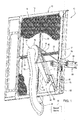
- a screen assembly 10 is positioned so that engine intake and cooling air must flow though it so debris can be removed by a mesh screen 9.
- the screen assembly 10 includes a rectangular (and square shaped) frame 12 which includes an outer frame 14 and a central hub 16.
- the frame 12 also includes frame arms 18, 20, 22 and 24 which extend between the hub 16 and the outer frame 14.
- the outer frame 14 surrounds and supports the mesh screen 9.
- each frame arm 18-22 has a recess or groove 26 in its side which faces the mesh screen 9.
- Each recess 26 receives an elongated member or rake bar 28 from which project a plurality of spaced-apart tabs 30.
- the mesh screen 9 is held by the outer frame 14 and extends over the frame arms 18-22 and is held in the grooves 26 by the rake bars 28.
- a hollow duct 32 extends from a first end 34 positioned exterior to the outer frame 14 to a second end 36 near the hub 16.
- the first end 34 is connected to a vacuum source 33, such as an auxiliary vacuum fan (not shown) or a shroud aspirator (not shown) mounted to the engine radiator shroud (not shown).
- a sweeping arm assembly 40 is rotatably connected to the second end 36.
- Sweeping arm assembly 40 includes a hollow arm 42 which has a radially inner end 44 fixed to a central hollow hub 41.
- a circular pulley 46 is fixed to and surrounds the hub 41.
- the arm 42 has a slot-shaped aperture 48 in the side facing the mesh screen 9 so that debris will be vacuumed off of the mesh screen 9, through the slot 48 and through the arm 42.
- the sweeping assembly 40 also includes a brush member or outer arm 50 which is movably coupled to the hollow or inner arm 42 and is movable radially inwardly and outwardly with respect to the arm 24.
- the brush member 50 includes a roller 52 which rotatable supported at its outer end.
- the roller 52 is attached to a pin 49 which is rotatably received by a bearing sleeve 51 which is attached to the outer end of brush member 50.
- the roller 52 rides along a track 54 formed by the outer frame 14.
- the position of the brush member 50 could be maintained by a cam-and-roller (not shown) located near the pivot axis of the arm 42. As best seen in Fig.
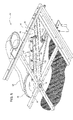
- track 54 includes a side wall 53 which extends around the inner edge of outer frame 14 and a lip 55 which projects outwardly from an edge of the side wall 53.
- the sweeping arm assembly 40 includes the inner arm 42 pivotally coupled to the duct 32 and the outer arm 50 which is movable with respect to the inner arm 42.
- Guide rods 56 and 58 are supported by a first bracket 60 which is fixed to the hub 41 and by a second bracket 62 which is fixed to an outer end of arm 42.
- Sleeves 64 and 66 are slidably mounted on the rods 56, 58.
- Brush member 50 has a housing 70 which is attached to the sleeves 64 and 66.
- a pair of springs 72 and 74 are mounted on the rods 56 and 58 between the sleeves 64 and 66 and the bracket 62. The springs are biased to urge the brush member 50 radially inwardly and to hold roller 52 to the track 54.
- a bracket 78 is attached to a side of the brush member housing 70.
- the bracket 78 supports a brush 80 which sweepingly engages the mesh screen 9 as the sweeping assembly pivots around the axis of the hub 41.
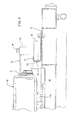
- the pulley 46 is rotated by a drive belt 82 which is driven by a drive pulley 84 which is attached to a drive shaft 86.
- Drive shaft 86 is rotatably supported by a bracket 88 which is attached to the outer frame 14.
- tension in the belt 82 is maintained by an idler pulley 90 which rotatably supported at and end of a lever member 92.
- Lever member 92 is pivotally supported on a pivot pin 94 which is supported by idler bracket 96 which is attached to the outer frame 14.
- An end portion of lever 92 forms a bracket 98 which has a bore 100 which slidably receives a tension adjust rod 102.
- a tension bracket 104 is fixed to the tension adjust rod 102.
- a spring 106 is mounted around the rod 102 between brackets 98 and bracket 104, and is biased to urge rod 102 to the right viewing Fig. 2 . This tends to pivot lever 92 counter-clockwise, viewing Fig. 2 and thus lessens the tension idler pulley 90 places on the belt 82.
- a pair of tension adjust nuts 108 are threadably screwed onto a threaded portion of rod 102.
- the slot 48 opens towards the mesh screen 9 so that it will vacuum debris off of the mesh screen 9.
- a comb member 110 is attached to a side of arm 42.
- Comb member 110 includes a plurality of spaced apart tabs 112 which project towards the mesh screen 9. These tabs 112 are preferably aligned with the spaces between the tabs 30 of rake bars 28, so that comb member 110 and rake bars 28 cooperate to break up larger pieces of debris which might otherwise clog up the vacuum ducts within the system 10.
- a brush 114 with flexible bristles is attached to the other side of arm 42, and sweepingly engages the mesh screen 9 as the sweeping assembly pivots around the axis of the hub 41.
- This system 10 allows full airflow exposure through the screen 9 to the engine cooling cores (not shown) and overcomes the limitations of previous rotary screen designs. As a result, engine cooling systems can perform better because they will have uniform airflow throughout the cores allowing better cooling.
- This invention can be used on agricultural harvesting machines like combines and forage harvesters and also allows the use of cores with higher heat rejection characteristics to be used in the same size envelope due to the increased airflow available.
Applications Claiming Priority (1)
| Application Number | Priority Date | Filing Date | Title |
|---|---|---|---|
| US13/183,544 US8974564B2 (en) | 2011-07-15 | 2011-07-15 | Screen cleaning system |
Publications (2)
| Publication Number | Publication Date |
|---|---|
| EP2546492A1 true EP2546492A1 (de) | 2013-01-16 |
| EP2546492B1 EP2546492B1 (de) | 2015-04-29 |
Family
ID=46395490
Family Applications (1)
| Application Number | Title | Priority Date | Filing Date |
|---|---|---|---|
| EP20120173086 Active EP2546492B1 (de) | 2011-07-15 | 2012-06-22 | Schirmreinigungssystem |
Country Status (2)
| Country | Link |
|---|---|
| US (1) | US8974564B2 (de) |
| EP (1) | EP2546492B1 (de) |
Cited By (6)
| Publication number | Priority date | Publication date | Assignee | Title |
|---|---|---|---|---|
| CN110404363A (zh) * | 2018-04-27 | 2019-11-05 | 贵州中烟工业有限责任公司 | 排潮滤网在线自动清洁装置 |
| EP3587939A1 (de) * | 2018-06-29 | 2020-01-01 | Mitsubishi Heavy Industries Thermal Systems, Ltd. | Filterreinigungseinheit und klimaanlage |
| EP3586595A1 (de) * | 2018-06-21 | 2020-01-01 | CLAAS Selbstfahrende Erntemaschinen GmbH | Kühlerkorb mit einer reinigungsvorrichtung |
| EP3597026A1 (de) * | 2018-06-21 | 2020-01-22 | CLAAS Selbstfahrende Erntemaschinen GmbH | Kühlvorrichtung |
| EP3696385A3 (de) * | 2019-02-12 | 2020-10-07 | CLAAS Selbstfahrende Erntemaschinen GmbH | Kühleinrichtung für eine landwirtschaftliche arbeitsmaschine |
| RU2783185C1 (ru) * | 2018-06-21 | 2022-11-09 | КЛААС Зельбстфаренде Эрнтемашинен ГмбХ | Охлаждающее устройство |
Families Citing this family (6)
| Publication number | Priority date | Publication date | Assignee | Title |
|---|---|---|---|---|
| BE1022785B1 (nl) * | 2015-03-04 | 2016-09-05 | Cnh Industrial Belgium Nv | Rotary dust screen |
| DE102018006701A1 (de) * | 2018-08-24 | 2020-02-27 | Maschinenfabrik Bernard Krone GmbH & Co. KG | Selbstfahrende Erntemaschine mit Kühlluftfilter |
| US11007465B2 (en) | 2018-11-09 | 2021-05-18 | Cnh Industrial America Llc | Rotating suction wand for a non-circular air screen |
| US11376946B2 (en) * | 2020-02-24 | 2022-07-05 | Deere & Company | Magnetic couplers for shaft assembly |
| CN116670389A (zh) * | 2020-10-02 | 2023-08-29 | 建筑机械股份有限公司 | 用于圆形旋转运动变换到非圆形旋转运动的方法及系统 |
| DE102022102795A1 (de) * | 2022-02-07 | 2023-08-10 | Claas Selbstfahrende Erntemaschinen Gmbh | Selbstfahrender Mähdrescher |
Citations (14)
| Publication number | Priority date | Publication date | Assignee | Title |
|---|---|---|---|---|
| US3377780A (en) * | 1966-08-04 | 1968-04-16 | W C Wiedenmann & Son Inc | Self-cleaning filter apparatus |
| US4443236A (en) | 1981-11-14 | 1984-04-17 | Deere & Company | Self-cleaning screen for the cooling air inlet of an engine enclosure |
| US4542785A (en) * | 1983-09-23 | 1985-09-24 | Massey-Ferguson Industries Limited | Agricultural harvester heat exchanger |
| EP0481203A1 (de) | 1990-10-19 | 1992-04-22 | Claas Ohg | Selbstfahrende Erntemaschine |
| EP0489975A1 (de) | 1990-12-11 | 1992-06-17 | New Holland Belgium N.V. | Reinigungsvorrichtung für ein Filterelement |
| US5183487A (en) | 1992-04-24 | 1993-02-02 | Deere & Company | Trash handling apparatus for a self-cleaning rotary screen |
| US5217512A (en) * | 1992-05-28 | 1993-06-08 | Pneumafil Corporation | Apparatus for filtering debris from a moving airstream |
| EP0667447A1 (de) | 1994-02-11 | 1995-08-16 | CLAAS Kommanditgesellschaft auf Aktien | Selbstfahrende Erntemaschine |
| DE19857681A1 (de) * | 1998-12-14 | 2000-06-15 | Krone Bernhard Gmbh Maschf | Landwirtschaftliche Erntemaschine |
| EP1035308A1 (de) * | 1999-03-10 | 2000-09-13 | CLAAS Selbstfahrende Erntemaschinen GmbH | Selbstfahrende Erntemaschine |
| DE10012766A1 (de) | 2000-03-16 | 2001-09-20 | Deere & Co | Reinigungseinrichtung eines Siebs |
| DE10103139A1 (de) | 2001-01-24 | 2002-07-25 | Alexander Wahler | Vorrichtung zum automatischen Reinigen des Netzes das vor den Kühler gebaut wird, um diesen sauber zu halten |
| DE10225090A1 (de) | 2002-06-05 | 2003-12-18 | Claas Selbstfahr Erntemasch | Kühlluft-Reinigungseinrichtung |
| US20090211208A1 (en) * | 2008-02-26 | 2009-08-27 | Johnson Brian K | Rotary vacuum apparatus for air screen |
Family Cites Families (4)
| Publication number | Priority date | Publication date | Assignee | Title |
|---|---|---|---|---|
| US3339348A (en) * | 1963-06-10 | 1967-09-05 | Microtron Corp | Air filter cleaner |
| US4509961A (en) * | 1983-06-17 | 1985-04-09 | Armstrong Jones Inc. | Air filter assembly |
| DE4017206C2 (de) * | 1990-05-29 | 1994-08-11 | Ltg Lufttechnische Gmbh | Filteranordnung mit mehreren Trommelfiltern |
| US8075650B2 (en) * | 2006-10-11 | 2011-12-13 | Emerson Electric Co. | System, method, and apparatus for mounting a filter bag to a wet/dry vacuum |
-
2011
- 2011-07-15 US US13/183,544 patent/US8974564B2/en active Active
-
2012
- 2012-06-22 EP EP20120173086 patent/EP2546492B1/de active Active
Patent Citations (14)
| Publication number | Priority date | Publication date | Assignee | Title |
|---|---|---|---|---|
| US3377780A (en) * | 1966-08-04 | 1968-04-16 | W C Wiedenmann & Son Inc | Self-cleaning filter apparatus |
| US4443236A (en) | 1981-11-14 | 1984-04-17 | Deere & Company | Self-cleaning screen for the cooling air inlet of an engine enclosure |
| US4542785A (en) * | 1983-09-23 | 1985-09-24 | Massey-Ferguson Industries Limited | Agricultural harvester heat exchanger |
| EP0481203A1 (de) | 1990-10-19 | 1992-04-22 | Claas Ohg | Selbstfahrende Erntemaschine |
| EP0489975A1 (de) | 1990-12-11 | 1992-06-17 | New Holland Belgium N.V. | Reinigungsvorrichtung für ein Filterelement |
| US5183487A (en) | 1992-04-24 | 1993-02-02 | Deere & Company | Trash handling apparatus for a self-cleaning rotary screen |
| US5217512A (en) * | 1992-05-28 | 1993-06-08 | Pneumafil Corporation | Apparatus for filtering debris from a moving airstream |
| EP0667447A1 (de) | 1994-02-11 | 1995-08-16 | CLAAS Kommanditgesellschaft auf Aktien | Selbstfahrende Erntemaschine |
| DE19857681A1 (de) * | 1998-12-14 | 2000-06-15 | Krone Bernhard Gmbh Maschf | Landwirtschaftliche Erntemaschine |
| EP1035308A1 (de) * | 1999-03-10 | 2000-09-13 | CLAAS Selbstfahrende Erntemaschinen GmbH | Selbstfahrende Erntemaschine |
| DE10012766A1 (de) | 2000-03-16 | 2001-09-20 | Deere & Co | Reinigungseinrichtung eines Siebs |
| DE10103139A1 (de) | 2001-01-24 | 2002-07-25 | Alexander Wahler | Vorrichtung zum automatischen Reinigen des Netzes das vor den Kühler gebaut wird, um diesen sauber zu halten |
| DE10225090A1 (de) | 2002-06-05 | 2003-12-18 | Claas Selbstfahr Erntemasch | Kühlluft-Reinigungseinrichtung |
| US20090211208A1 (en) * | 2008-02-26 | 2009-08-27 | Johnson Brian K | Rotary vacuum apparatus for air screen |
Cited By (6)
| Publication number | Priority date | Publication date | Assignee | Title |
|---|---|---|---|---|
| CN110404363A (zh) * | 2018-04-27 | 2019-11-05 | 贵州中烟工业有限责任公司 | 排潮滤网在线自动清洁装置 |
| EP3586595A1 (de) * | 2018-06-21 | 2020-01-01 | CLAAS Selbstfahrende Erntemaschinen GmbH | Kühlerkorb mit einer reinigungsvorrichtung |
| EP3597026A1 (de) * | 2018-06-21 | 2020-01-22 | CLAAS Selbstfahrende Erntemaschinen GmbH | Kühlvorrichtung |
| RU2783185C1 (ru) * | 2018-06-21 | 2022-11-09 | КЛААС Зельбстфаренде Эрнтемашинен ГмбХ | Охлаждающее устройство |
| EP3587939A1 (de) * | 2018-06-29 | 2020-01-01 | Mitsubishi Heavy Industries Thermal Systems, Ltd. | Filterreinigungseinheit und klimaanlage |
| EP3696385A3 (de) * | 2019-02-12 | 2020-10-07 | CLAAS Selbstfahrende Erntemaschinen GmbH | Kühleinrichtung für eine landwirtschaftliche arbeitsmaschine |
Also Published As
| Publication number | Publication date |
|---|---|
| EP2546492B1 (de) | 2015-04-29 |
| US8974564B2 (en) | 2015-03-10 |
| US20130014341A1 (en) | 2013-01-17 |
Similar Documents
| Publication | Publication Date | Title |
|---|---|---|
| EP2546492B1 (de) | Schirmreinigungssystem | |
| EP2147712B1 (de) | Reinigung eines Luftfiltersiebs eines landwirtschaftlichen Fahrzeugs | |
| US4439218A (en) | Screen cleaning means | |
| KR101823452B1 (ko) | 청소기 헤드 | |
| JP4850273B2 (ja) | フィルタ殺菌装置 | |
| US6974487B2 (en) | Cooling air cleaning device for a harvesting machine | |
| CN105380570A (zh) | 清洁头 | |
| US6248145B1 (en) | Cleaner for rotating air-intake filter | |
| CA2335659C (en) | Cleaning arrangement of a sieve | |
| JP2008029912A (ja) | フィルタ用清掃装置 | |
| US20090288655A1 (en) | Grease filter assembly for | |
| US20070022720A1 (en) | Cleaner for cooling system screen of outdoor power equipment unit | |
| JPWO2004081461A1 (ja) | エアフィルタの自動清掃機能付き室内ユニットを備えた空気調和機 | |
| JP2004283703A (ja) | 空気調和機のフィルター装置 | |
| CN105286720B (zh) | 吸尘器及其吸刷 | |
| CN111165163B (zh) | 用于非圆形空气筛网的抽吸棒 | |
| JP2011050962A (ja) | 空気調和機 | |
| JP2007198678A (ja) | フィルタ装置および空気調和機 | |
| US10995772B2 (en) | Agricultural harvester cooler box with debris guard | |
| CN100398935C (zh) | 过滤器装置 | |
| WO2012159847A1 (en) | Air filtration system | |
| JP2005140405A (ja) | 空気調和機 | |
| JP2007101106A (ja) | 空気調和機のフィルター装置 | |
| JP3807452B2 (ja) | 空気調和機 | |
| JP2007101107A (ja) | 空気調和機 |
Legal Events
| Date | Code | Title | Description |
|---|---|---|---|
| PUAI | Public reference made under article 153(3) epc to a published international application that has entered the european phase |
Free format text: ORIGINAL CODE: 0009012 |
|
| AK | Designated contracting states |
Kind code of ref document: A1 Designated state(s): AL AT BE BG CH CY CZ DE DK EE ES FI FR GB GR HR HU IE IS IT LI LT LU LV MC MK MT NL NO PL PT RO RS SE SI SK SM TR |
|
| AX | Request for extension of the european patent |
Extension state: BA ME |
|
| 17P | Request for examination filed |
Effective date: 20130716 |
|
| RBV | Designated contracting states (corrected) |
Designated state(s): AL AT BE BG CH CY CZ DE DK EE ES FI FR GB GR HR HU IE IS IT LI LT LU LV MC MK MT NL NO PL PT RO RS SE SI SK SM TR |
|
| GRAP | Despatch of communication of intention to grant a patent |
Free format text: ORIGINAL CODE: EPIDOSNIGR1 |
|
| INTG | Intention to grant announced |
Effective date: 20141205 |
|
| GRAS | Grant fee paid |
Free format text: ORIGINAL CODE: EPIDOSNIGR3 |
|
| GRAA | (expected) grant |
Free format text: ORIGINAL CODE: 0009210 |
|
| AK | Designated contracting states |
Kind code of ref document: B1 Designated state(s): AL AT BE BG CH CY CZ DE DK EE ES FI FR GB GR HR HU IE IS IT LI LT LU LV MC MK MT NL NO PL PT RO RS SE SI SK SM TR |
|
| REG | Reference to a national code |
Ref country code: GB Ref legal event code: FG4D |
|
| REG | Reference to a national code |
Ref country code: CH Ref legal event code: EP |
|
| REG | Reference to a national code |
Ref country code: AT Ref legal event code: REF Ref document number: 724573 Country of ref document: AT Kind code of ref document: T Effective date: 20150515 |
|
| REG | Reference to a national code |
Ref country code: IE Ref legal event code: FG4D |
|
| REG | Reference to a national code |
Ref country code: DE Ref legal event code: R096 Ref document number: 602012006967 Country of ref document: DE Effective date: 20150611 |
|
| REG | Reference to a national code |
Ref country code: NL Ref legal event code: VDEP Effective date: 20150429 |
|
| REG | Reference to a national code |
Ref country code: AT Ref legal event code: MK05 Ref document number: 724573 Country of ref document: AT Kind code of ref document: T Effective date: 20150429 |
|
| REG | Reference to a national code |
Ref country code: LT Ref legal event code: MG4D |
|
| PG25 | Lapsed in a contracting state [announced via postgrant information from national office to epo] |
Ref country code: NL Free format text: LAPSE BECAUSE OF FAILURE TO SUBMIT A TRANSLATION OF THE DESCRIPTION OR TO PAY THE FEE WITHIN THE PRESCRIBED TIME-LIMIT Effective date: 20150429 |
|
| PG25 | Lapsed in a contracting state [announced via postgrant information from national office to epo] |
Ref country code: ES Free format text: LAPSE BECAUSE OF FAILURE TO SUBMIT A TRANSLATION OF THE DESCRIPTION OR TO PAY THE FEE WITHIN THE PRESCRIBED TIME-LIMIT Effective date: 20150429 Ref country code: FI Free format text: LAPSE BECAUSE OF FAILURE TO SUBMIT A TRANSLATION OF THE DESCRIPTION OR TO PAY THE FEE WITHIN THE PRESCRIBED TIME-LIMIT Effective date: 20150429 Ref country code: HR Free format text: LAPSE BECAUSE OF FAILURE TO SUBMIT A TRANSLATION OF THE DESCRIPTION OR TO PAY THE FEE WITHIN THE PRESCRIBED TIME-LIMIT Effective date: 20150429 Ref country code: PT Free format text: LAPSE BECAUSE OF FAILURE TO SUBMIT A TRANSLATION OF THE DESCRIPTION OR TO PAY THE FEE WITHIN THE PRESCRIBED TIME-LIMIT Effective date: 20150831 Ref country code: NO Free format text: LAPSE BECAUSE OF FAILURE TO SUBMIT A TRANSLATION OF THE DESCRIPTION OR TO PAY THE FEE WITHIN THE PRESCRIBED TIME-LIMIT Effective date: 20150729 Ref country code: LT Free format text: LAPSE BECAUSE OF FAILURE TO SUBMIT A TRANSLATION OF THE DESCRIPTION OR TO PAY THE FEE WITHIN THE PRESCRIBED TIME-LIMIT Effective date: 20150429 |
|
| PG25 | Lapsed in a contracting state [announced via postgrant information from national office to epo] |
Ref country code: LV Free format text: LAPSE BECAUSE OF FAILURE TO SUBMIT A TRANSLATION OF THE DESCRIPTION OR TO PAY THE FEE WITHIN THE PRESCRIBED TIME-LIMIT Effective date: 20150429 Ref country code: IS Free format text: LAPSE BECAUSE OF FAILURE TO SUBMIT A TRANSLATION OF THE DESCRIPTION OR TO PAY THE FEE WITHIN THE PRESCRIBED TIME-LIMIT Effective date: 20150829 Ref country code: GR Free format text: LAPSE BECAUSE OF FAILURE TO SUBMIT A TRANSLATION OF THE DESCRIPTION OR TO PAY THE FEE WITHIN THE PRESCRIBED TIME-LIMIT Effective date: 20150730 Ref country code: RS Free format text: LAPSE BECAUSE OF FAILURE TO SUBMIT A TRANSLATION OF THE DESCRIPTION OR TO PAY THE FEE WITHIN THE PRESCRIBED TIME-LIMIT Effective date: 20150429 Ref country code: AT Free format text: LAPSE BECAUSE OF FAILURE TO SUBMIT A TRANSLATION OF THE DESCRIPTION OR TO PAY THE FEE WITHIN THE PRESCRIBED TIME-LIMIT Effective date: 20150429 |
|
| PG25 | Lapsed in a contracting state [announced via postgrant information from national office to epo] |
Ref country code: EE Free format text: LAPSE BECAUSE OF FAILURE TO SUBMIT A TRANSLATION OF THE DESCRIPTION OR TO PAY THE FEE WITHIN THE PRESCRIBED TIME-LIMIT Effective date: 20150429 Ref country code: DK Free format text: LAPSE BECAUSE OF FAILURE TO SUBMIT A TRANSLATION OF THE DESCRIPTION OR TO PAY THE FEE WITHIN THE PRESCRIBED TIME-LIMIT Effective date: 20150429 Ref country code: MC Free format text: LAPSE BECAUSE OF FAILURE TO SUBMIT A TRANSLATION OF THE DESCRIPTION OR TO PAY THE FEE WITHIN THE PRESCRIBED TIME-LIMIT Effective date: 20150429 |
|
| REG | Reference to a national code |
Ref country code: CH Ref legal event code: PL |
|
| REG | Reference to a national code |
Ref country code: DE Ref legal event code: R097 Ref document number: 602012006967 Country of ref document: DE |
|
| PG25 | Lapsed in a contracting state [announced via postgrant information from national office to epo] |
Ref country code: PL Free format text: LAPSE BECAUSE OF FAILURE TO SUBMIT A TRANSLATION OF THE DESCRIPTION OR TO PAY THE FEE WITHIN THE PRESCRIBED TIME-LIMIT Effective date: 20150429 Ref country code: SK Free format text: LAPSE BECAUSE OF FAILURE TO SUBMIT A TRANSLATION OF THE DESCRIPTION OR TO PAY THE FEE WITHIN THE PRESCRIBED TIME-LIMIT Effective date: 20150429 Ref country code: CZ Free format text: LAPSE BECAUSE OF FAILURE TO SUBMIT A TRANSLATION OF THE DESCRIPTION OR TO PAY THE FEE WITHIN THE PRESCRIBED TIME-LIMIT Effective date: 20150429 Ref country code: LU Free format text: LAPSE BECAUSE OF FAILURE TO SUBMIT A TRANSLATION OF THE DESCRIPTION OR TO PAY THE FEE WITHIN THE PRESCRIBED TIME-LIMIT Effective date: 20150622 Ref country code: RO Free format text: LAPSE BECAUSE OF NON-PAYMENT OF DUE FEES Effective date: 20150429 |
|
| PLBE | No opposition filed within time limit |
Free format text: ORIGINAL CODE: 0009261 |
|
| STAA | Information on the status of an ep patent application or granted ep patent |
Free format text: STATUS: NO OPPOSITION FILED WITHIN TIME LIMIT |
|
| REG | Reference to a national code |
Ref country code: IE Ref legal event code: MM4A |
|
| REG | Reference to a national code |
Ref country code: FR Ref legal event code: ST Effective date: 20160229 |
|
| 26N | No opposition filed |
Effective date: 20160201 |
|
| PG25 | Lapsed in a contracting state [announced via postgrant information from national office to epo] |
Ref country code: CH Free format text: LAPSE BECAUSE OF NON-PAYMENT OF DUE FEES Effective date: 20150630 Ref country code: LI Free format text: LAPSE BECAUSE OF NON-PAYMENT OF DUE FEES Effective date: 20150630 Ref country code: IE Free format text: LAPSE BECAUSE OF NON-PAYMENT OF DUE FEES Effective date: 20150622 |
|
| PG25 | Lapsed in a contracting state [announced via postgrant information from national office to epo] |
Ref country code: SI Free format text: LAPSE BECAUSE OF FAILURE TO SUBMIT A TRANSLATION OF THE DESCRIPTION OR TO PAY THE FEE WITHIN THE PRESCRIBED TIME-LIMIT Effective date: 20150429 Ref country code: FR Free format text: LAPSE BECAUSE OF NON-PAYMENT OF DUE FEES Effective date: 20150630 |
|
| PG25 | Lapsed in a contracting state [announced via postgrant information from national office to epo] |
Ref country code: MT Free format text: LAPSE BECAUSE OF FAILURE TO SUBMIT A TRANSLATION OF THE DESCRIPTION OR TO PAY THE FEE WITHIN THE PRESCRIBED TIME-LIMIT Effective date: 20150429 |
|
| GBPC | Gb: european patent ceased through non-payment of renewal fee |
Effective date: 20160622 |
|
| PG25 | Lapsed in a contracting state [announced via postgrant information from national office to epo] |
Ref country code: GB Free format text: LAPSE BECAUSE OF NON-PAYMENT OF DUE FEES Effective date: 20160622 Ref country code: SM Free format text: LAPSE BECAUSE OF FAILURE TO SUBMIT A TRANSLATION OF THE DESCRIPTION OR TO PAY THE FEE WITHIN THE PRESCRIBED TIME-LIMIT Effective date: 20150429 Ref country code: BG Free format text: LAPSE BECAUSE OF FAILURE TO SUBMIT A TRANSLATION OF THE DESCRIPTION OR TO PAY THE FEE WITHIN THE PRESCRIBED TIME-LIMIT Effective date: 20150429 Ref country code: HU Free format text: LAPSE BECAUSE OF FAILURE TO SUBMIT A TRANSLATION OF THE DESCRIPTION OR TO PAY THE FEE WITHIN THE PRESCRIBED TIME-LIMIT; INVALID AB INITIO Effective date: 20120622 |
|
| PG25 | Lapsed in a contracting state [announced via postgrant information from national office to epo] |
Ref country code: SE Free format text: LAPSE BECAUSE OF FAILURE TO SUBMIT A TRANSLATION OF THE DESCRIPTION OR TO PAY THE FEE WITHIN THE PRESCRIBED TIME-LIMIT Effective date: 20150429 Ref country code: CY Free format text: LAPSE BECAUSE OF FAILURE TO SUBMIT A TRANSLATION OF THE DESCRIPTION OR TO PAY THE FEE WITHIN THE PRESCRIBED TIME-LIMIT Effective date: 20150429 |
|
| PG25 | Lapsed in a contracting state [announced via postgrant information from national office to epo] |
Ref country code: TR Free format text: LAPSE BECAUSE OF FAILURE TO SUBMIT A TRANSLATION OF THE DESCRIPTION OR TO PAY THE FEE WITHIN THE PRESCRIBED TIME-LIMIT Effective date: 20150429 |
|
| PG25 | Lapsed in a contracting state [announced via postgrant information from national office to epo] |
Ref country code: MK Free format text: LAPSE BECAUSE OF FAILURE TO SUBMIT A TRANSLATION OF THE DESCRIPTION OR TO PAY THE FEE WITHIN THE PRESCRIBED TIME-LIMIT Effective date: 20150429 |
|
| PG25 | Lapsed in a contracting state [announced via postgrant information from national office to epo] |
Ref country code: AL Free format text: LAPSE BECAUSE OF FAILURE TO SUBMIT A TRANSLATION OF THE DESCRIPTION OR TO PAY THE FEE WITHIN THE PRESCRIBED TIME-LIMIT Effective date: 20150429 |
|
| PGFP | Annual fee paid to national office [announced via postgrant information from national office to epo] |
Ref country code: IT Payment date: 20220621 Year of fee payment: 11 |
|
| PGFP | Annual fee paid to national office [announced via postgrant information from national office to epo] |
Ref country code: DE Payment date: 20230522 Year of fee payment: 12 |
|
| PGFP | Annual fee paid to national office [announced via postgrant information from national office to epo] |
Ref country code: BE Payment date: 20230627 Year of fee payment: 12 |