EP2544905B1 - Strukturell gestütztes nicht pneumatisches rad mit durchgehender laufverstärkungsbaugruppe - Google Patents
Strukturell gestütztes nicht pneumatisches rad mit durchgehender laufverstärkungsbaugruppe Download PDFInfo
- Publication number
- EP2544905B1 EP2544905B1 EP11754151.6A EP11754151A EP2544905B1 EP 2544905 B1 EP2544905 B1 EP 2544905B1 EP 11754151 A EP11754151 A EP 11754151A EP 2544905 B1 EP2544905 B1 EP 2544905B1
- Authority
- EP
- European Patent Office
- Prior art keywords
- band
- melt temperature
- flexible cylindrical
- pneumatic wheel
- continuous loop
- Prior art date
- Legal status (The legal status is an assumption and is not a legal conclusion. Google has not performed a legal analysis and makes no representation as to the accuracy of the status listed.)
- Active
Links
- 230000002787 reinforcement Effects 0.000 title claims description 110
- 230000003014 reinforcing effect Effects 0.000 claims description 128
- 239000000463 material Substances 0.000 claims description 90
- 125000006850 spacer group Chemical group 0.000 claims description 88
- 239000011159 matrix material Substances 0.000 claims description 30
- 229920000642 polymer Polymers 0.000 claims description 29
- 239000000835 fiber Substances 0.000 claims description 27
- 239000011148 porous material Substances 0.000 claims description 14
- 239000000155 melt Substances 0.000 claims description 13
- 230000001747 exhibiting effect Effects 0.000 claims 1
- 238000002844 melting Methods 0.000 description 15
- 230000008018 melting Effects 0.000 description 15
- 230000006835 compression Effects 0.000 description 14
- 238000007906 compression Methods 0.000 description 14
- 238000010348 incorporation Methods 0.000 description 9
- 238000000034 method Methods 0.000 description 7
- 229920002635 polyurethane Polymers 0.000 description 7
- 239000004814 polyurethane Substances 0.000 description 7
- 239000002184 metal Substances 0.000 description 6
- 229910052751 metal Inorganic materials 0.000 description 6
- 239000002861 polymer material Substances 0.000 description 6
- 238000005452 bending Methods 0.000 description 5
- 239000004744 fabric Substances 0.000 description 5
- 239000006261 foam material Substances 0.000 description 5
- 229920001247 Reticulated foam Polymers 0.000 description 4
- 230000008901 benefit Effects 0.000 description 4
- 238000012423 maintenance Methods 0.000 description 4
- 239000007787 solid Substances 0.000 description 4
- OKTJSMMVPCPJKN-UHFFFAOYSA-N Carbon Chemical compound [C] OKTJSMMVPCPJKN-UHFFFAOYSA-N 0.000 description 3
- 229910000831 Steel Inorganic materials 0.000 description 3
- 239000004760 aramid Substances 0.000 description 3
- 229920003235 aromatic polyamide Polymers 0.000 description 3
- 229910052799 carbon Inorganic materials 0.000 description 3
- 238000010276 construction Methods 0.000 description 3
- 238000004519 manufacturing process Methods 0.000 description 3
- 238000012986 modification Methods 0.000 description 3
- 230000004048 modification Effects 0.000 description 3
- 239000012858 resilient material Substances 0.000 description 3
- 239000010959 steel Substances 0.000 description 3
- JOYRKODLDBILNP-UHFFFAOYSA-N Ethyl urethane Chemical compound CCOC(N)=O JOYRKODLDBILNP-UHFFFAOYSA-N 0.000 description 2
- 239000000853 adhesive Substances 0.000 description 2
- 230000001070 adhesive effect Effects 0.000 description 2
- 230000015572 biosynthetic process Effects 0.000 description 2
- 239000004917 carbon fiber Substances 0.000 description 2
- 210000004027 cell Anatomy 0.000 description 2
- 229920001971 elastomer Polymers 0.000 description 2
- 239000003365 glass fiber Substances 0.000 description 2
- 230000008569 process Effects 0.000 description 2
- 238000012545 processing Methods 0.000 description 2
- 230000035939 shock Effects 0.000 description 2
- 230000006641 stabilisation Effects 0.000 description 2
- 238000011105 stabilization Methods 0.000 description 2
- 238000005406 washing Methods 0.000 description 2
- 239000004593 Epoxy Substances 0.000 description 1
- 229920005830 Polyurethane Foam Polymers 0.000 description 1
- 230000009471 action Effects 0.000 description 1
- 238000007792 addition Methods 0.000 description 1
- 230000004075 alteration Effects 0.000 description 1
- 230000009286 beneficial effect Effects 0.000 description 1
- 210000002421 cell wall Anatomy 0.000 description 1
- 238000003486 chemical etching Methods 0.000 description 1
- 239000002131 composite material Substances 0.000 description 1
- 239000004035 construction material Substances 0.000 description 1
- 238000001816 cooling Methods 0.000 description 1
- 238000013461 design Methods 0.000 description 1
- 230000000694 effects Effects 0.000 description 1
- 239000000806 elastomer Substances 0.000 description 1
- 239000013536 elastomeric material Substances 0.000 description 1
- 239000012530 fluid Substances 0.000 description 1
- 239000006260 foam Substances 0.000 description 1
- 239000011521 glass Substances 0.000 description 1
- 230000006872 improvement Effects 0.000 description 1
- 230000007246 mechanism Effects 0.000 description 1
- 239000000203 mixture Substances 0.000 description 1
- 238000000465 moulding Methods 0.000 description 1
- 239000004745 nonwoven fabric Substances 0.000 description 1
- 229920003023 plastic Polymers 0.000 description 1
- 239000004033 plastic Substances 0.000 description 1
- 239000011496 polyurethane foam Substances 0.000 description 1
- 238000005096 rolling process Methods 0.000 description 1
- 230000035945 sensitivity Effects 0.000 description 1
- 230000000087 stabilizing effect Effects 0.000 description 1
- 239000000725 suspension Substances 0.000 description 1
- 239000011800 void material Substances 0.000 description 1
- 239000002023 wood Substances 0.000 description 1
- 239000002759 woven fabric Substances 0.000 description 1
Images


Classifications
-
- B—PERFORMING OPERATIONS; TRANSPORTING
- B60—VEHICLES IN GENERAL
- B60C—VEHICLE TYRES; TYRE INFLATION; TYRE CHANGING; CONNECTING VALVES TO INFLATABLE ELASTIC BODIES IN GENERAL; DEVICES OR ARRANGEMENTS RELATED TO TYRES
- B60C7/00—Non-inflatable or solid tyres
- B60C7/04—Non-inflatable or solid tyres made of wood or leather
-
- B—PERFORMING OPERATIONS; TRANSPORTING
- B60—VEHICLES IN GENERAL
- B60C—VEHICLE TYRES; TYRE INFLATION; TYRE CHANGING; CONNECTING VALVES TO INFLATABLE ELASTIC BODIES IN GENERAL; DEVICES OR ARRANGEMENTS RELATED TO TYRES
- B60C7/00—Non-inflatable or solid tyres
-
- B—PERFORMING OPERATIONS; TRANSPORTING
- B60—VEHICLES IN GENERAL
- B60C—VEHICLE TYRES; TYRE INFLATION; TYRE CHANGING; CONNECTING VALVES TO INFLATABLE ELASTIC BODIES IN GENERAL; DEVICES OR ARRANGEMENTS RELATED TO TYRES
- B60C7/00—Non-inflatable or solid tyres
- B60C7/10—Non-inflatable or solid tyres characterised by means for increasing resiliency
- B60C7/101—Tyre casings enclosing a distinct core, e.g. foam
- B60C7/1015—Tyre casings enclosing a distinct core, e.g. foam using foam material
-
- B—PERFORMING OPERATIONS; TRANSPORTING
- B60—VEHICLES IN GENERAL
- B60C—VEHICLE TYRES; TYRE INFLATION; TYRE CHANGING; CONNECTING VALVES TO INFLATABLE ELASTIC BODIES IN GENERAL; DEVICES OR ARRANGEMENTS RELATED TO TYRES
- B60C7/00—Non-inflatable or solid tyres
- B60C7/22—Non-inflatable or solid tyres having inlays other than for increasing resiliency, e.g. for armouring
-
- B—PERFORMING OPERATIONS; TRANSPORTING
- B60—VEHICLES IN GENERAL
- B60C—VEHICLE TYRES; TYRE INFLATION; TYRE CHANGING; CONNECTING VALVES TO INFLATABLE ELASTIC BODIES IN GENERAL; DEVICES OR ARRANGEMENTS RELATED TO TYRES
- B60C9/00—Reinforcements or ply arrangement of pneumatic tyres
- B60C9/18—Structure or arrangement of belts or breakers, crown-reinforcing or cushioning layers
- B60C9/1807—Structure or arrangement of belts or breakers, crown-reinforcing or cushioning layers comprising fabric reinforcements
-
- B—PERFORMING OPERATIONS; TRANSPORTING
- B60—VEHICLES IN GENERAL
- B60C—VEHICLE TYRES; TYRE INFLATION; TYRE CHANGING; CONNECTING VALVES TO INFLATABLE ELASTIC BODIES IN GENERAL; DEVICES OR ARRANGEMENTS RELATED TO TYRES
- B60C9/00—Reinforcements or ply arrangement of pneumatic tyres
- B60C9/18—Structure or arrangement of belts or breakers, crown-reinforcing or cushioning layers
- B60C2009/1871—Structure or arrangement of belts or breakers, crown-reinforcing or cushioning layers with flat cushions or shear layers between belt layers
-
- B—PERFORMING OPERATIONS; TRANSPORTING
- B60—VEHICLES IN GENERAL
- B60C—VEHICLE TYRES; TYRE INFLATION; TYRE CHANGING; CONNECTING VALVES TO INFLATABLE ELASTIC BODIES IN GENERAL; DEVICES OR ARRANGEMENTS RELATED TO TYRES
- B60C7/00—Non-inflatable or solid tyres
- B60C7/10—Non-inflatable or solid tyres characterised by means for increasing resiliency
- B60C7/107—Non-inflatable or solid tyres characterised by means for increasing resiliency comprising lateral openings
-
- B—PERFORMING OPERATIONS; TRANSPORTING
- B60—VEHICLES IN GENERAL
- B60C—VEHICLE TYRES; TYRE INFLATION; TYRE CHANGING; CONNECTING VALVES TO INFLATABLE ELASTIC BODIES IN GENERAL; DEVICES OR ARRANGEMENTS RELATED TO TYRES
- B60C7/00—Non-inflatable or solid tyres
- B60C7/10—Non-inflatable or solid tyres characterised by means for increasing resiliency
- B60C7/14—Non-inflatable or solid tyres characterised by means for increasing resiliency using springs
- B60C7/146—Non-inflatable or solid tyres characterised by means for increasing resiliency using springs extending substantially radially, e.g. like spokes
Definitions
- the present invention relates to a non-pneumatic wheel. More particularly, the invention relates to non-pneumatic wheel having a continuous loop reinforcement assembly that can support a load and have performance similar to pneumatic tires.
- the pneumatic tire is a known solution for compliance, comfort, mass, and rolling resistance; however, the pneumatic tire has disadvantages in complexity, the need for maintenance, and susceptibility to damage.
- a device that improves on pneumatic tire performance could, for example, provide more compliance, better control of stiffness, lower maintenance requirements, and resistance to damage.
- solid and cushion tires typically include a solid rim surrounded by a resilient material layer. These tires rely on compression of the ground-contacting portion of the resilient layer directly under the load for load support. These types of tires can be heavy and stiff and lack the shock absorbing capability of pneumatic tires.
- Spring tires typically have a rigid wood, metal or plastic ring with springs or spring like elements connecting it to a hub. While the hub is thereby suspended by the springs, the inflexible ring has only a small contact area with the road, which offers essentially no compliance, and provides poor traction and steering control.
- a non-pneumatic wheel having performance characteristics similar to pneumatic wheel would be useful. More particularly, a non-pneumatic wheel that does not require an air inflation pressure in order to provide performance characteristics of a pneumatic tire would be beneficial. Such a non-pneumatic wheel that can a constructed with a hub or connected to a hub for mounting on a vehicle or other transport device would also be very useful.
- the present invention provides a non-pneumatic wheel that defines radial, circumferential, and transverse directions.
- the wheel includes an annular band supporting a ground contacting tread portion and extending about the circumferential direction.
- a continuous loop reinforcement assembly is positioned within the annular band.
- a mounting band is positioned radially-inward of the annular band.
- a plurality of web spokes are connected to, and extending radially between, the annular band and the mounting band.
- the continuous loop reinforcement assembly can include a first flexible cylindrical band and a second flexible cylindrical band positioned apart from, and radially outward of, the first flexible cylindrical band.
- One or both of the first flexible cylindrical band and the second flexible cylindrical band can include a coil comprising one or more materials wound into a helix and at least one retainer attached to the coil and configured for maintaining the integrity of the coil.
- the one or more materials of the coil can include materials selected from the group comprising metal, steel, carbon, aramid, and glass.
- the at least one retainer can include a higher melt temperature material and a lower melt temperature material.
- the higher melt temperature material and the lower melt temperature material can be configured in a core/sheath arrangement.
- the at least one retainer can include one or more of the group comprising a monofilament yarn, multifilament yarn, and staple fiber yarns.
- the at least one retainer can include a tie reinforcing yarn and a structural reinforcing yarn having a greater stiffness than the tie reinforcing yarn.
- the tie reinforcing yarn can include a material having a lower melt temperature than the melt temperature of the structural reinforcing yarn.
- the structural reinforcing yarn can have a low shrinkage when heated to the lower melt temperature of the tie reinforcing yarn.
- the tie reinforcing yarn can include a lower melt temperature polymer and a higher melt temperature polymer, wherein the higher melt temperature polymer exhibits shrinkage when heated to the melt temperature of the lower melt temperature polymer.
- the at least one retainer can include a plurality of reinforcing yarns woven into the coil in a leno weave with cross-overs of the yarns occurring between the one or more materials of the coil.
- the at least one retainer can include a plurality of reinforcing yarns tied the coil in a Malimo style stitch knit pattern.
- the continuous loop reinforcement assembly can include a spacer positioned between the first flexible cylindrical band and the second flexible cylindrical band.
- the spacer can include a porous material, which may be e.g., a reticulated foam.
- the annular band may include a matrix material that is received into the porous material of the spacer.
- the matrix material may be constructed from e.g., a polyurethane.
- the continuous loop reinforcement assembly can include a plurality of spacers positioned between the first flexible cylindrical band and the second flexible cylindrical band.
- the continuous loop reinforcement assembly can include a plurality of flexible cylindrical bands that are spaced apart from each other along the radial direction.
- the present invention provides a non-pneumatic wheel having a continuous loop reinforcement assembly that can support a load and have performance similar to pneumatic tires.
- Various configurations of a non-pneumatic wheel, including variations of the continuous loop reinforcement assembly, are provided.
- One or more resilient spacers can be positioned with the continuous loop reinforcement assembly and can be configured for the receipt of a matrix material.
- the continuous loop reinforcement assembly 10 provides reinforcement for a matrix material, such as an epoxy, polyurethane, or other elastomer. Assembly 10 can be incorporated into a non-pneumatic wheel to provide compliant, structural reinforcement as will be further described.
- the continuous loop reinforcement assembly 10 is porous for receiving the matrix material and being embedded within a non-pneumatic wheel.
- the continuous loop reinforcement assembly 10 in the present invention is flexible in the radial direction to provide for distributing radial forces applied to the non-pneumatic wheel that is reinforced by the continuous loop reinforcement assembly 10.
- continuous loop reinforcement means the inclusion or one or more yarns or cables that are wound into a helix that includes at least three revolutions. More specifically, the one or more yarns or cables continue around to itself without the use of a seam across the band.
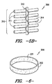
- the continuous loop reinforcement assembly 10 includes a first flexible cylindrical reinforcement band 100, a second flexible cylindrical reinforcement band 300, and a intermediate resilient spacer 200 disposed between the first flexible cylindrical reinforcement band 100 and the second flexible cylindrical reinforcement band 300.
- the first flexible cylindrical reinforcement band 100 has a first band inner surface 101 and a first band outer surface 102.
- the second flexible cylindrical reinforcement band 300 has a second band inner surface 301 and a second band outer surface 302.
- the intermediate resilient spacer 200 ( FIG. 6 ) has a spacer inner surface 201 that engages the first band outer surface 102, and a spacer outer surface 202 that engages the second band inner surface 301.
- the first flexible cylindrical band 100 ( FIG. 2 ) is a cylindrical member with flexibility in the radial direction.
- the first flexible cylindrical band 100 has a flexibility wherein the first flexible cylindrical band 100 can be subjected to a bend radius that is one-tenth or less of its normal inside diameter in the continuous loop reinforcing assembly 10 without experiencing a permanent set to the material. Because the first flexible cylindrical band 100 is a reinforcing component of the continuous loop reinforcing assembly 10, the Young's Modulus of the material in the first flexible cylindrical band 100 along its tangential direction will be greater than the Young's Modulus of the matrix reinforced by the first cylindrical band 100. In one preferred embodiment, the Young's Modulus of the first flexible cylindrical band 100 is at least 1,000 times greater than the Young's Modulus of the matrix reinforced by the first flexible cylindrical band 100.
- the first flexible cylindrical band 100 comprises a continuous band of a coil 110 ( FIGS. 3A and 3B ), such as a coil formed from one or more yarns or cables 111 wound into a helix, each cable 1 I making at least three revolutions around the first flexible cylindrical band 100.
- a "continuous band” is a band that continues around to itself without the use of a seam across the band.
- the cables 111 have high longitudinal tension and compression stiffness, and flexibility in the tangential direction. Preferred materials for the cables 111 would include high modulus materials such as metal, steel, carbon, aramid, or glass fibers.
- the retainers 112 can attach to cable 111 for maintaining the integrity of the coil 110.
- the retainers 112 can be a polymeric material woven into the cables 111, a metal strip crimped to the cables 111, or the like.
- the retainers 112 provide an axial stiffness to the first flexible cylindrical band 100 prior to incorporation of the matrix material with the continuous loop reinforcement assembly 10.
- the reinforcing yarns 112a and 112b can be different ends of a single yarn, or two different yarns.
- the reinforcing yarns 112a and 112b are woven or knitted longitudinally into the coil 110 in between the cables 111.
- the reinforcing yarns 112a and 112b need to be flexible enough to incorporate into the coil 110, but provide axial stiffness to the first flexible cylindrical reinforcement band 100.
- At least one of the reinforcing yarns 112a and 112b comprise polymeric yarn with a higher melt temperature material and a lower melt temperature material.
- both of the reinforcing yarns 112a and 112b comprise polymeric yarns with a higher melt temperature material and a lower melt temperature material.
- the reinforcing yarns 112a and 112b Prior to any melt bonding of the two melt temperature materials, the reinforcing yarns 112a and 112b are incorporated into the coil 110. In this manner, the reinforcing yarns 112a and 112b are flexible enough to be incorporated into the coil 110 with minimum difficulty.
- the sub-assembly is subjected to a temperature above the melt temperature of the lower melt temperature material, and below the melt temperature of the higher melt temperature material. After the lower melt temperature material is melted, the temperature is lowered below its melt temperature, melt bonding the lower melt temperature material to the higher temperature material thereby creating a fused reinforcing spacing yarn.
- the retainer 112 formed by the yarns becomes more rigid. This extra rigidity provides the first flexible cylindrical band with an increased axial stiffness.
- the lower melt temperature material of the reinforcing yarns have a melt temperature above the formation or cure temperature of the matrix.
- the reinforcing yarns 112a and 112b using different melt temperature materials can be formed of a fiber or fibers having the materials with the different melting points, such as core/sheath fibers, or can be formed from a combination of fibers having different melting points.
- the reinforcing yarns 112a and 112b can be monofilament yarns, multifilament yarns, or staple fiber yarns.
- the higher melt temperature material of such reinforcing yarns be selected to have sufficient elasticity to reduce the likelihood of assembly problems. It is also preferable that the higher melt temperature material of such reinforcing yarns be selected to have low shrinkage characteristics, particularly when subjected to the heat of fusing the reinforcing yarns and incorporation of the matrix material into the continuous loop reinforcement assembly.
- the filament or fibers are a core and sheath configuration with the higher melt temperature polymer being the core and the lower melt temperature polymer being the sheath.
- the yarn comprises filaments or fibers of the higher melt temperature polymer and separate filaments or fibers of the lower melt temperature polymer.
- reinforcing yarn 112a is illustrated as a structural yarn and reinforcing yarn 112b is illustrated as a tie yarn.
- the structural reinforcing yarn 112a is stiffer and heavier than the tie reinforcing yarn 112b.
- the structural reinforcing yarn 112a provides axial rigidity to the coil 110.
- the reinforcing yarn 112a can be secured to the outside or the inside of the coil 110.
- the structural reinforcing yarn 112a is a monofilament yarn.
- the tie reinforcing yarn 112b secures the cables 111 of the coil adjacent to the structural reinforcing yarn 112a.
- the tie reinforcing yarn 112b includes a lower melt temperature polymer material as described above, and can include a higher melt temperature polymer material as described above.
- the melt temperature of the lower melt temperature polymer material in the tie yarn is a lower temperature than the melt temperature of the primary materials in the structural reinforcing yarn 112a. In this manner, the tie reinforcing yarn 112b can be used to better secure the cables 111 of the coil 110 to the structural reinforcing yarn.
- the structural reinforcing yarn 112a When using a tie reinforcing yarn 112b having a polymer with a lower melting temperature, it is preferred that the structural reinforcing yarn 112a have low shrinkage when subject to the melting temperature of the lower melting temperature polymer in the tie reinforcing yarn 112b, such as with a heat set polymer yarn.
- the tie reinforcing yarn 112b includes filaments or staple fibers with the lower melt temperature, and filaments or staple fibers of the higher melting temperature.
- the tie reinforcing yarn 112b includes filaments or staple fibers of both lower melt temperature and high melt temperature polymer
- the filament with the high melt temperature polymer have some shrink during melting of the lower melt temperature polymer, such as with a yarn that is not heat set, thereby cinching up the connection between the structural reinforcing yarn 112a and the at least one cable 111 of the coil 110.
- FIGS. 3A and 3B there are shown two different patterns for the reinforcing yarns 112a and 112b.
- the reinforcing yarns 112a and 112b secure the cables 111 of the coil 110 with a weave pattern.
- the reinforcing yarns 112a and 112b are woven into the coil 110 in a leno weave, with crossovers of the yarns occurring between cables.
- the reinforcing yarns 112a and 112b could be incorporated into the coil 110 with other weave patterns.
- FIG. 3B the reinforcing yarns 112a and 112b secure the cables 111 of the coil 110 with a Malimo style stitch knit pattern.
- the reinforcing yarns 112a and 112b could be incorporated into the coil 110 with other knit patterns.
- FIGS. 3A and 3B illustrate the reinforcing yarns 112a and 112b as being incorporated into the coil 110 with a weave or knit pattern, a series of single reinforcing yarns 112 could also be wound through the coil 110.
- the second flexible cylindrical band 300 is a cylindrical member with flexibility in the radial direction.
- the second flexible cylindrical band 300 has a flexibility wherein the second flexible cylindrical band 300 can be subjected to a bend radius that is one-tenth or less of its normal inside diameter in the continuous loop reinforcing assembly 10 without experiencing a permanent set to the material. Because the second flexible cylindrical band 300 is a reinforcing component of the continuous loop reinforcing assembly 10, the Young's Modulus of the material in the second flexible cylindrical band 300 in the tangential direction will be greater than the Young's Modulus of the matrix reinforced by the second flexible cylindrical band 300. In one preferred embodiment, the Young's Modulus of the second flexible cylindrical band 300 is at least 1,000 times greater than the Young's Modulus of the matrix reinforced by the second flexible cylindrical band 300.
- the second flexible cylindrical band 300 comprises a continuous band of a coil 310, such as a coil formed from one or more cables 311 wound into a helix, each cable 311 making at least three revolutions around the second flexible cylindrical band 300.
- the cables 311 have high longitudinal tension and compression stiffness, and flexibility in the tangential direction. Preferred materials for the cables 311 would include high modulus materials such as metal, steel, carbon, aramid, or glass fibers.
- Multiple retainers 312 can attach to cable 311 for maintaining the integrity of the coil 310.
- Retainers 312 can be a polymeric material woven into the cables 311, a metal strip crimped to the cables 311, or the like. The retainers 312 provide an axial stiffness to the second flexible cylindrical band 300 prior to incorporation of the matrix material with the continuous loop reinforcement assembly 10.
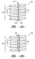
- FIGS. 5A and 5B there are shown two embodiment of the second flexible cylindrical band 300 with the retainers 312 comprising reinforcing yarns 312a and 312b.
- the reinforcing yarns 312a and 312b can be different ends of a single yarn, or two different yarns.
- the reinforcing yarns 312a and 312b are woven longitudinally into the coil 310 in between the cables 311.
- the reinforcing yearns 312a and 312b need to be flexible enough to be incorporated into the coil 310, but provide axial stiffness to the second flexible cylindrical reinforcement band 300.
- At least one of the reinforcing yarns 312a and 312b comprise polymeric yarn with a higher melt temperature material and a lower melt temperature material.
- both of the reinforcing yarns 312a and 312b comprise polymeric yarns with a higher melt temperature material and a lower melt temperature material.
- the reinforcing yarns 312a and 312b Prior to any melt bonding of the two melt temperature materials, the reinforcing yarns 312a and 312b are incorporated into the coil 310. In this manner, the reinforcing yarns 312a and 312b are flexible enough to be incorporated into the coil 310 with minimum difficulty.
- the subassembly is subjected to a temperature above the melt temperature of the lower melt temperature material, and below the melt temperature of the higher melt temperature material. After the lower melt temperature material is melted, the temperature is lowered below its melt temperature, melt bonding the lower melt temperature material to the higher temperature material thereby creating a fused reinforcing spacing yarn.
- the retainer 312 formed by the yarns becomes more rigid. This extra rigidity provides the first flexible cylindrical band with an increased axial stiffness.
- the lower melt temperature material of the reinforcing yarns have a melt temperature above the formation or cure temperature of the matrix.
- the reinforcing yarns 312a and 312b using different melt temperature materials can be formed of a fiber or fibers having the materials with the different melting points, such as core/sheath fibers, or can be formed from a combination of fibers having different melting points.
- the reinforcing yarns 312a and 312b can be monofilament yarns, multifilament yarns, or staple yarns.
- the higher melt temperature material of such reinforcing yarns be selected to have sufficient elasticity to reduce the likelihood of assembly problems. It is also preferable that the higher melt temperature material of such reinforcing yarns be selected to have low shrinkage characteristics, particularly when subjected to the heat of fusing the reinforcing yarns and incorporation of the matrix material into the continuous loop reinforcement assembly.
- the filament or fibers are a core and sheath configuration with the higher melt temperature polymer being the core and the lower melt temperature polymer being the sheath.
- the yarn comprises filaments or fibers of the higher melt temperature polymer and separate filaments or fibers of the lower melt temperature polymer.
- reinforcing yarn 312a is illustrated as a structural yarn and reinforcing yarn 312b is illustrated as a tie yarn.
- the structural reinforcing yarn 312a is stiffer and heavier than the tie reinforcing yarn 312b.
- the structural reinforcing yarn 312a provides axial rigidity to the coil 310.
- the reinforcing yarn 312a can be secured to the outside or the inside of the coil 310.
- the structural reinforcing yarn 312a is a monofilament yarn.
- the tie reinforcing yarn 312b secures the cables 311 of the coil adjacent to the structural reinforcing yarn 312a.
- the tie reinforcing yarn 312b includes a lower melt temperature polymer material as described above, and can include a higher melt temperature polymer material as described above.
- the melt temperature of the lower melt temperature polymer material in the tie yarn is a lower temperature than the primary materials in the structural reinforcing yarn 312a. In this manner, the tie reinforcing yarn 312b can be used to better secure the cables 311 of the coil 310 to the structural reinforcing yarn.
- the structural reinforcing yarn 312a When using a tie reinforcing yarn 312b having a polymer with a lower melting temperature, it is preferred that the structural reinforcing yarn 312a have low shrinkage when subject to the melting temperature of the lower melting temperature polymer in the tie reinforcing yarn 312b, such as with a heat set polymer yarn.
- the tie reinforcing yarn 312b includes filaments or staple fibers with the lower melt temperature, and filaments or staple fibers of the higher melting temperature.
- the tie reinforcing yarn 312b includes filaments or staple fibers of both lower melt temperature and high melt temperature polymer
- the filament with the high melt temperature polymer have some shrink during melting of the lower melt temperature polymer, such as with a yarn that is not heat set, thereby cinching up the connection between the structural reinforcing yarn 312a and the at least one cable 311 of the coil 310.
- FIGS. 5A and 5B there are shown two different patterns for the reinforcing yarns 312a and 312b.
- the reinforcing yarns 312a and 312b secure the cables 311 of the coil 310 with a weave pattern.
- the reinforcing yarns 312a and 312b are woven into the coil 310 in a leno weave, with crossovers of the yarns occurring between cables.
- the reinforcing yarns 312a and 312b could be incorporated into the coil 310 with other weave patterns.
- FIG. 5A the reinforcing yarns 312a and 312b secure the cables 311 of the coil 310 with a weave pattern.
- the reinforcing yarns 312a and 312b are woven into the coil 310 in a leno weave, with crossovers of the yarns occurring between cables.
- the reinforcing yarns 312a and 312b could be incorporated into the coil 310 with other weave patterns.
- FIG. 5A the reinforc
- the reinforcing yarns 312a and 312b secure the cables 311 of the coil 310 with a Malimo style stitch knit pattern.
- the reinforcing yarns 312a and 312b could be incorporated into the coil 310 with other knit patterns.
- FIGS. 5A and 5B illustrate the reinforcing yarns 312a and 312b as being incorporated into the coil 310 with a weave or knit pattern, a series of single reinforcing yarns 312 could also be wound through the coil 310.
- the intermediate resilient spacer 200 is a resilient material that applies a constant pressure to the first band outer surface 102 and the second band inner surface 301. What is meant by resilient is that the resilient spacer generates increasing reaction forces with increasing amounts of compression.
- the thickness of the intermediate resilient spacer 200 in the radial direction is greater than the space created between the first flexible cylindrical reinforcement band 100 and the second flexible cylindrical reinforcement band 300 in the radial direction. In this manner, the intermediate resilient spacer 200 exerts constant pressure between the two flexible cylindrical reinforcement bands 100, 300, around the continuous loop reinforcement assembly 10.
- the intermediate resilient spacer 200 preferably has a substantially uniform thickness and is substantially uniform in composition.
- This constant even pressure maintains the spatial relationship between the first flexible cylindrical band 100 and the second flexible cylindrical reinforcement band 300.
- the even pressure between the first flexible cylindrical reinforcement band 100 and the second flexible cylindrical reinforcement band 300 creates a force equilibrium that will maintain centering of the two bands even if there are variations in the diameter of the first or second flexible cylindrical bands 100, 300.
- caution must be exercised to prevent excessive pressure on the first flexible cylindrical reinforcement band 100.
- the intermediate resilient spacer 200 exerts excessive pressure on the first flexible cylindrical reinforcement band 100, the first flexible cylindrical reinforcement band 100 will buckle deforming the shape.
- the intermediate resilient spacer 200 can elastically recover from at least 30% compression.
- the materials forming the intermediate resilient spacer 200 can elastically recover from greater than an 80% compression.
- the intermediate resilient spacer 200 holds itself and the two reinforcing bands 100, 300, in place without additional fixation.
- the normal pressure and resulting friction between the intermediate resilient spacer 200 and the two reinforcing bands 100, 300 is sufficient to stabilize the continuous loop reinforcement assembly 10, even during incorporation of the matrix material when forming a cylindrical member.
- the intermediate resilient spacer 200 exerts a pressure between the two flexible cylindrical reinforcing bands 100, 300, it also creates a bulge of the spacer material between the cables 111, 311. This bulge between the cables 111, 311, results in further stabilization of the continuous loop reinforcing assembly 10 and helps stabilize the position of the individual cables 111, 311, within the flexible cylindrical reinforcing bands 100, 300, respectively.
- the intermediate resilient spacer 200 can use a material with very small protrusions or arms that hold the cables 111, 311, thereby stabilizing the position of the individual cables 111, 311, within the cylindrical reinforcing bands 100, 300, respectively.
- the stabilization of the reinforcing bands 100, 300, and the intermediate resilient spacer 200 can be improved with adhesives and material geometry that provides a gripping effect between the intermediate resilient spacer 200 and the flexible cylindrical reinforcing bands 100, 300.
- Increased friction, adhesion, or gripping between the intermediate resilient spacer 200 and the first flexible cylindrical reinforcing band 100 will also increase the pressure that can be exerted by the intermediate resilient spacer 200 to the first flexible cylindrical reinforcing band 100 before the onset of buckling of the first flexible cylindrical reinforcing band 100.
- the intermediate resilient spacer 200 is also porous for receiving the matrix material that is reinforced.
- the intermediate resilient spacer 200 is porous without closed voids or torturous flow paths that reverse flow direction or create dead end flows.
- a porous material will include voids reducing the volume of the mass making up the porous material. It is preferable to increase the void area in a porous material by reducing the volume of the mass in a porous material to the minimum practical amount.
- the volume of the mass forming the porous material may have a maximum volume of forty percent (40%).
- the volume of the mass forming the porous material may have a maximum volume of fifteen percent (15%).
- the volume of the mass forming the porous material has a maximum volume of five percent (5%).
- the intermediate resilient spacer 200 comprises the same material as in the matrix, such as polyurethane.
- the intermediate resilient spacer 200 is a flexible member. Flexing of the intermediate resilient spacer 200 facilitates the assembly of the continuous loop reinforcement assembly 10, and allows the final reinforced matrix member to flex without functional damage to the components of continuous loop reinforcement assembly 10 or the matrix. Similar to the first flexible cylindrical reinforcement band 100 and the second flexible cylindrical reinforcement band 300, it is preferable that the intermediate resilient spacer 200 have a flexibility wherein the intermediate resilient spacer 200 can be subjected to a bend radius that is one-tenth or less of its normal inside diameter in the continuous loop reinforcement assembly 10 without experiencing a permanent set to the material. In another preferred embodiment, the intermediate spacer 200 has a greater flexibility than the cylindrical reinforcement bands that it engages.
- the intermediate resilient spacer 200 can be a strip of material that is cut to the desired thickness, width, and length, and then inserted between the first reinforcement band 100 and the second reinforcement band 300.
- the ends of the strip of material are attached to form the intermediate resilient spacer 200.
- the strip of material placed between the first reinforcement band 100 and the second reinforcement band 300 as the intermediate resilient spacer 200 is a strip of material that is not attached at the ends with the ends loosely abutting each other. In some instances, it may be acceptable to have a small gap between the ends of a material forming the intermediate resilient spacer 200.
- the axial width of the intermediate resilient spacer 200 does not always need to equal the full width of the reinforcement bands 100 or 300.
- the intermediate resilient spacer 200 is a foam material.
- the foam material can be an open cell foam material.
- a reticulated foam material provides a porous resilient material for the intermediate resilient spacer 200.
- cell walls are removed by methods such as passing a controlled flame or chemical etching fluid through the medium.
- the remaining material of the reticulated foam can also provide arms that secure the cables 111, 311, within the cylindrical reinforcing bands 100, 300.
- the foam material can be the same material as the matrix to be reinforced.
- polyurethane foam can be used as the intermediate resilient spacer 200 in a cylindrical reinforcing member 10 to reinforce a polyurethane matrix.
- the intermediate resilient spacer 200 is a nonwoven material.
- One type of nonwoven material that could be used as the spacer is a nonwoven material with thick filaments which are formed into a three-dimensional shape, such as a two or three dimensional corrugated configuration.
- Nonwovens with thickness oriented, or "z" oriented, fibers can provide resilient properties to the nonwoven.
- the intermediate resilient spacer 200 is a spacer fabric.
- a spacer fabric is a knit or woven fabric that has two face layers separated by fibers or yarns extending between the two layers. The fibers between the two layers provide a spring-like force that opposes the compression of the spacer fabric. Considerations for the spacer fabric would be openness, pore shape, pore size, stiffness, direction of the separating fiber or yarn, ability of material to adhere to the matrix material, and the like.
- FIG. 7 there is shown an embodiment of the present invention with the intermediate resilient spacer 200 having a width smaller than the width of the first cylindrical reinforcement band 100 or the second cylindrical reinforcement band 300.
- the intermediate resilient spacer 200 is centered in the width direction of the continuous loop reinforcement assembly 10.
- the flexible cylindrical reinforcement bands 100, 300 are designed to maintain a constant spatial relationship between each other at widths beyond the intermediate resilient spacer 200.
- FIG. 8 there is shown an embodiment of the present invention with the first flexible cylindrical reinforcement band 100 and the second flexible cylindrical reinforcement band 300 being spaced apart by two intermediate resilient spacers 200a and 200b.
- the intermediate resilient spacers 200a and 200b are narrower than the flexible cylindrical reinforcement bands 100, 300, and are disposed towards opposing outer edges of the flexible cylindrical reinforcement bands 100, 300.
- FIG. 9 there is shown an embodiment of the present invention where a third flexible cylindrical reinforcement band 500 is disposed outside of the second flexible cylindrical reinforcement band 300, and a second intermediate resilient spacer 400 is disposed between the second flexible cylindrical reinforcement band 300 and the third cylindrical reinforcement band 500.
- the third flexible cylindrical reinforcement band 500 has the same properties and characteristics as the first flexible cylindrical reinforcement band 100 or the second flexible reinforcement band 300.
- the second intermediate resilient spacer 400 also has the same properties and characteristics as the intermediate flexible resilient spacer 200. It is contemplated that the cylindrical reinforcement assembly of the present invention could have multiple layers of cylindrical reinforcement bands separated by one or more intermediate, resilient layers.
- continuous loop reinforcement assembly 10 can be manufactured without a resilient spacer as well. More specifically, referring to FIG. 1 , continuous loop reinforcement assembly 10 can be created without resilient spacer 200. In such case, care should be taken to maintain the proper spacing of reinforcement bands 100 and 300 while manufacturing assembly 10. For example, between properly spaced reinforcement bands 100 and 300, a material could by dripped or drizzled so as not to disturb the spacing there-between. Such material should have a relatively high viscosity and should solidify while touching reinforcement bands 100 and 300 so as to maintain proper spacing. Preferably, such material will also have a higher melting temperature than the material used for construction of reinforcement bands 100 and 300. Other methods for manufacturing a continuous loop reinforcement assembly without a resilient spacer may be used as well.
- FIG. 10 provides a perspective view of an exemplary embodiment of a structurally supported wheel 401 in accordance with the present invention.
- structurally supported means that the tire carries a load by its structural components without the support of gas inflation pressure.
- FIG. 11 provides a partial, cross-sectional view of wheel 401 taken along line 11-11 as shown in FIG. 10 .
- Arrows C denote the circumferential direction.
- Arrow R denotes the radial direction.
- Arrows A denotes axial direction, also referred to sometimes as the transverse or lateral direction.
- continuous loop reinforcement assembly 10 is positioned within a band 405 extending about circumferential direction C.
- assembly 10 includes first flexible cylindrical band 100 and second flexible cylindrical band 300 separated by resilient spacer 200 as previously described.
- Bands 100 and 300 provide e.g., vertical stiffness for wheel 401 while resilient spacer 200 assists in providing for a shear layer for wheel 401 as will be further described.
- wheel 401 is useful in applications where the traction, steering, or suspension qualities of a pneumatic tire are advantageous or in need of improvement.
- a structurally supported wheel 401 constructed in accordance with the present invention as more fully described below can offer improved compliance and stiffness characteristics, in a wheel requiring less maintenance than a pneumatic tire.
- such a wheel could also be advantageously used, for example, on a wheel chair, a gurney, a hospital bed, a cart for sensitive equipment, or other vehicles or conveyances where sensitivity to shock is important.
- the wheel may be used in place of casters for chairs or other furniture, or as wheels for baby carriages, skate boards, in-line skates, etc.
- Wheel 401 of the invention could be used in machines or apparatuses where load bearing or load applying wheels are used.
- vehicle is used below for the purposes of the description; however, any device on which compliant wheels could be mounted is included in the following description and “vehicle” should be understood to include the same.
- Wheel 401 as shown in FIGS. 10 and 11 has an annular band 405 and a plurality of tension transmitting elements, illustrated as web spokes 420, extending transversely across and inward from band 405, to a mounting band 425 at the radially inner end of the web spokes 420.
- Mounting band 425 anchors wheel 401 to a hub 430.
- a tread portion 410 is formed at the outer periphery of band 405.
- Tread portion 410 may be an additional layer bonded on the band 405, for example, to provide different traction and wear properties than the material used to construct band 405.
- tread portion 410 may be formed as part of the outer surface of the compliant band, as shown in FIG. 10 .
- Tread features may be formed in the tread portion 410 and may include blocks 415 and grooves 440.
- web spokes 420 in the exemplary embodiment of FIGS. 10 and 11 extend transversely across wheel 401, which as used herein means that the web spokes 420 extend from side to side of wheel 401 and may be aligned with the axis of rotation, or may be oblique to the wheel axis.
- "extending inward" means that web spokes 420 extend between band 405 and mounting band 425, and may lie in a plane radial to the wheel axis or may be oblique to the radial plane.
- web spokes 420 may actually include spokes at different angles to the radial plane.
- Various shapes and patterns may be used as shown, e.g., in U.S. Patent No. 7,013,939 .
- Band 405 supports the load on wheel 401 and resiliently deforms to conform to the road (or other supporting surface) to provide traction and handling capabilities. More particularly, as described in U.S. Patent No. 7,013,939 , when a load is placed on the wheel 401 through hub 430, band 405 acts compliantly in that it bends and otherwise deforms for ground contact and forms a contact patch, which is the portion of wheel 401 that is in contact with the ground under such load. The portion of band 405 that is not in ground contact acts in a manner similar to an arch and provides a circumferential compression stiffness and a longitudinal bending stiffness in the equatorial plane sufficiently high to act as a load-supporting member.
- equatorial plane means a plane that passes perpendicular to the wheel axis of rotation and bisects the wheel structure.
- band 405 can envelop obstacles to provide a smoother ride. Also, band 405 is able to transmit forces to the ground or road for traction, cornering, and steering.
- the load is supported by compression of the tire structure in the contact area, which includes compression of the cushion material under the rigid hub. Compliance of the cushion material is limited by the compression properties of the material and the thickness of the material on the rigid wheel or hub.
- web spokes 420 are substantially sheet-like elements having a length L in the radial direction, a width W in the axial direction corresponding generally to the axial width of the compliant band 405, although other widths W may be used including widths W that vary along the radial direction as shown in FIG. 11 .
- Web spokes 420 also have a thickness (i.e. a dimension perpendicular to length L and width W) that is generally much less than either the length L or the width W, which allows a web spoke to buckle or bend when under compression. Thinner web spokes will bend when passing through the contact area with substantially no compressive resistance, that is, supplying no or only insignificant compressive force to load bearing.
- the web spokes may provide some compressive load bearing force in the ground contact area.
- the predominant load transmitting action of web spokes 420 as a whole, however, is in tension.
- the particular web spoke thickness may be selected to meet the specific requirements of the vehicle or application.
- web spokes 420 are oriented relative to the compliant band 405 across the axial direction A. Tension in web spokes 420 is, therefore, distributed across band 405 to support the load.
- web spokes 420 may be formed of an elastomeric material having a tensile modulus of about 10 to 100 MPa.
- Web spokes 420 may be reinforced if desired.
- the material used to construct web spoke material 420 should also exhibit elastic behavior to return to original length after being strained to e.g., 30%, and to exhibit constant stress when the web spoke material is strained to e.g,. 4%.
- commercially available rubber or polyurethane materials can be identified which meet these requirements.
- Vibrathane B836 brand urethane from Chemtura Corporation of Middlebury, Conn. has been suitable for construction of web spoke 420.
- web spokes 420 are interconnected by radially inner mounting band 425, which encircles the hub 430 to mount wheel 401 to the hub 430.
- hub 430, mounting band 425, annular band 405, and web spokes 420 may be molded as single unit.
- one or more of such components may be formed separately and then attached to each other through e.g., adhesives or molding.
- other components may be included as well.
- an interface band can be used to connect web spokes 420 at their radially outer ends, and then the interface band would be connected to band 405.
- web spokes 420 could be mechanically attached to hub 430, for example, by providing an enlarged portion on the inner end of each web spoke 420 that engages a slot device in hub 430, or by attaching adjacent web spokes 420 to form a loop at a hook or bar formed in hub 430.
- Substantially purely tensile load support is obtained by having a web spoke 420 that has high effective stiffness in tension but very low stiffness in compression.
- web spokes 420 may be curved.
- web spokes 420 can be molded with a curvature and straightened by thermal shrinkage during cooling to provide a predisposition to bending in a particular direction.
- Web spokes 420 should resist torsion between annular band 405 and hub 430, for example, when torque is applied to wheel 401.
- web spokes 420 should resist lateral deflection when, for example, turning or cornering.
- web spokes 420 that lie in the radial-axial plane, that is, are aligned with both the radial and axial directions will have high resistance to axially directed forces, but, particularly if elongated in the radial direction R, may have relatively low resistance to torque in the circumferential direction C.
- a web spoke package having relatively short spokes 420 aligned with the radial direction R will be suitable.
- orientations of web spokes are provided that include a force-resisting component in both the radial and the circumferential directions, thus adding resistance to torque, while retaining radial and lateral force-resisting components.
- the angle of orientation may be selected depending on the number of web spokes used and the spacing between adjacent web spokes. Other alternative arrangements may also be used.
- One advantage of the compliant wheel of the invention is that the selection of the size and arrangement of band 405 and web spokes 420 allows the vertical, lateral, and torsional stiffness of the wheel to be tuned independently of the contact pressure and of each other.
- the operating parameters of band 405, load carrying and compliance are determined in part by selection of materials having the circumferential compression stiffness and longitudinal bending stiffness in the equatorial plane to meet the design load requirements. These parameters are examined in view of the diameter of wheel 401, the width of annular band 405 in the axial direction A, the thickness of band 405 in radial direction R, and the length and spacing of web spokes 420.
- the number of web spokes is selected to maintain circularity of band 405, and will depend also on the spacing between adjacent web spokes 420.
- band 405 includes continuous loop reinforcement assembly 10, which may be e.g., molded integrally as part of non-pneumatic wheel 401 or constructed separately and then attached with the other elements of wheel 401.
- resilient spacer 200 is porous, the matrix material used to construct band 405 may also be used to impregnate spacer 200 by passing into and through its porous material.
- resilient spacer 200 may be constructed as an open cell foam into which a polymer such as a polyurethane is received.
- a polyurethane suitable for such construction includes e.g., Vibrathane B836 brand urethane from Chemtura Corporation of Middlebury, Conn.
- FIG. 11 provides just one exemplary embodiment of a band 405 as may be used with the present invention.
- FIG. 12 provides another example of a band 405 as may be used in wheel 401 (web spokes 420 are omitted from this cross-sectional view as well as the views of FIGS. 13 and 14 ).
- the continuous loop reinforcement assembly 10 of FIG. 7 is shown incorporated into band 405.
- resilient spacer 200 is more narrow than first flexible cylindrical band 100 or second flexible cylindrical band 300.
- Resilient spacer 200 may be constructed as previously described.
- FIG. 13 provides another example of a band 405 as may be used in wheel 401, in which band 405 includes the continuous loop reinforcement assembly 10 of FIG. 8 .
- resilient spacer 200 is constructed from two intermediate resilient spacers 200a and 200b.
- a space 435 is shown between spacers 200a and 200b. Space 435 may be open or may be filled with matrix material.
- Resilient spacers 200a and 200b may be constructed as previously described for spacer 200.
- FIG. 14 provides still another example of a band 405 as may be used in wheel 401, in which band 405 includes the continuous loop reinforcement assembly 10 of FIG. 9 .
- resilient spacer 200 is constructed from two resilient spacers 200 and 400 and includes a third flexible cylindrical reinforcement band 500.
- FIG. 14 is provided by way of example only, multiple additional spacers and flexible cylindrical bands may be added as well depending upon the application.
Landscapes
- Engineering & Computer Science (AREA)
- Mechanical Engineering (AREA)
- Life Sciences & Earth Sciences (AREA)
- Wood Science & Technology (AREA)
- Tires In General (AREA)
- Ropes Or Cables (AREA)
- Yarns And Mechanical Finishing Of Yarns Or Ropes (AREA)
Claims (15)
- Nicht-pneumatisches Rad (401), wobei das Rad eine Radial-, eine Umfangsrichtung und eine Querrichtung definiert, wobei das Rad Folgendes umfasst:ein ringförmiges Band (405) zum Tragen eines den Boden berührenden Laufflächenabschnitts, wobei sich das ringförmige Band (405) um die Umfangsrichtung erstreckt,ein Montageband (425), das in Radialrichtung nach innen von dem ringförmigen Band (405) angeordnet ist, undmehrere Stegspeichen, die mit dem ringförmigen Band (405) und dem Montageband (425) verbunden sind und sich in Radialrichtung zwischen denselben erstrecken,dadurch gekennzeichnet, dasseine durchgehende Ringverstärkungsbaugruppe innerhalb des ringförmigen Bandes (405) angeordnet ist, wobei die durchgehende Ringverstärkungsbaugruppe ein oder mehrere Fäden oder Seile umfasst, die zu wenigstens einer Spirale gewunden sind, die mehrere Umdrehungen um die Umfangsrichtung einschließt.
- Nicht-pneumatisches Rad (401) nach Anspruch 1, wobei die durchgehende Ringverstärkungsbaugruppe Folgendes umfasst:ein erstes flexibles zylindrisches Band (100) undein zweites flexibles zylindrisches Band (300), das entfernt von dem ersten flexiblen zylindrischen Band (100) und in Radialrichtung von demselben nach außen angeordnet ist.
- Nicht-pneumatisches Rad (401) nach Anspruch 2, wobei eines oder beide von dem ersten flexiblen zylindrischen Band (100) und dem zweiten flexiblen zylindrischen Band (300) Folgendes umfassen:eine Spule, die ein oder mehrere Materialien umfasst, die zu einer Spirale gewunden sind, undwenigstens einen Halter (112), der an der Spule (110) befestigt und dafür konfiguriert ist, die Integrität der Spule (110) aufrechtzuerhalten.
- Nicht-pneumatisches Rad (401) nach Anspruch 3, wobei der wenigstens eine Halter (112)
ein Material mit höherer Schmelztemperatur und
ein Material mit niedrigerer Schmelztemperatur. - Nicht-pneumatisches Rad (401) nach Anspruch 4, wobei das Material mit höherer Schmelztemperatur und das Material mit niedrigerer Schmelztemperatur in einer Kern-Hülle-Anordnung konfiguriert sind.
- Nicht-pneumatisches Rad (401) nach Anspruch 3, wobei der wenigstens eine Halter (112) eines oder mehrere aus der Gruppe umfasst, die einen Monofilamentfaden, einen Multifilamentfaden und Stapelfaserfäden umfasst.
- Nicht-pneumatisches Rad (401) nach Anspruch 3, wobei der wenigstens eine Halter (112) Folgendes umfasst:einen Zugverstärkungsfaden undeinen Strukturverstärkungsfaden, der eine größere Steifigkeit hat als der Zugverstärkungsfaden.
- Nicht-pneumatisches Rad (401) nach Anspruch 7, wobei der Zugverstärkungsfaden ein Material umfasst, das eine Schmelztemperatur hat, die niedriger ist als die Schmelztemperatur des Strukturverstärkungsfadens.
- Nicht-pneumatisches Rad (401) nach Anspruch 7, wobei der der Zugverstärkungsfaden Folgendes umfasst:ein Polymer mit niedrigerer Schmelztemperatur undein Polymer mit höherer Schmelztemperatur, wobei das Polymer mit höherer Schmelztemperatur Schrumpfung zeigt, wenn es auf die Schmelztemperatur des Polymers mit niedrigerer Schmelztemperatur erhitzt wird.
- Nicht-pneumatisches Rad (401) nach Anspruch 3, wobei der wenigstens eine Halter (112) mehrere Verstärkungsfäden umfasst, die in einer Dreherbindung in die Spule (110) gewebt sind, wobei Überkreuzungen der Fäden zwischen dem einen oder den mehreren Materialien der Spule (110) auftreten.
- Nicht-pneumatisches Rad (401) nach Anspruch 2, wobei die durchgehende Ringverstärkungsbaugruppe ferner einen Abstandsalter (200) umfasst, der zwischen dem ersten flexiblen zylindrischen Band (100) und dem zweiten flexiblen zylindrischen Band angeordnet ist.
- Nicht-pneumatisches Rad (401) nach Anspruch 11, wobei der Abstandsalter (200) ein poröses Material umfasst.
- Nicht-pneumatisches Rad (401) nach Anspruch 12, wobei das ringförmige Band (405) ein Matrixmaterial umfasst, das in dem porösen Material des Abstandsalters (200) aufgenommen wird.
- Nicht-pneumatisches Rad (401) nach Anspruch 2, wobei die durchgehende Ringverstärkungsbaugruppe ferner mehrere Abstandsalter umfasst, die zwischen dem ersten flexiblen zylindrischen Band (100) und dem zweiten flexiblen zylindrischen Band angeordnet sind.
- Nicht-pneumatisches Rad (401) nach Anspruch 2, wobei die durchgehende Ringverstärkungsbaugruppe mehrere flexible zylindrische Bänder umfasst, wobei die zylindrischen Bänder entfernt voneinander entlang der Radialrichtung angeordnet sind.
Applications Claiming Priority (3)
| Application Number | Priority Date | Filing Date | Title |
|---|---|---|---|
| US12/661,196 US20110223366A1 (en) | 2010-03-12 | 2010-03-12 | Reinforced continuous loop matrix member; continuous loop reinforcement assembly; flexible cylindrical reinforcement band; and axially reinforced cylindrical coil |
| US201061428074P | 2010-12-29 | 2010-12-29 | |
| PCT/US2011/028078 WO2011112920A1 (en) | 2010-03-12 | 2011-03-11 | Structually supported, non-pneumatic wheel with continuous loop reinforcement assembly |
Publications (3)
| Publication Number | Publication Date |
|---|---|
| EP2544905A1 EP2544905A1 (de) | 2013-01-16 |
| EP2544905A4 EP2544905A4 (de) | 2014-04-02 |
| EP2544905B1 true EP2544905B1 (de) | 2015-11-04 |
Family
ID=44563862
Family Applications (1)
| Application Number | Title | Priority Date | Filing Date |
|---|---|---|---|
| EP11754151.6A Active EP2544905B1 (de) | 2010-03-12 | 2011-03-11 | Strukturell gestütztes nicht pneumatisches rad mit durchgehender laufverstärkungsbaugruppe |
Country Status (8)
| Country | Link |
|---|---|
| US (1) | US9272576B2 (de) |
| EP (1) | EP2544905B1 (de) |
| JP (1) | JP5588062B2 (de) |
| KR (1) | KR101433700B1 (de) |
| CN (1) | CN102791496B (de) |
| BR (1) | BR112012022942B1 (de) |
| RU (1) | RU2519576C2 (de) |
| WO (1) | WO2011112920A1 (de) |
Families Citing this family (44)
| Publication number | Priority date | Publication date | Assignee | Title |
|---|---|---|---|---|
| JP5745090B2 (ja) * | 2010-12-29 | 2015-07-08 | コンパニー ゼネラール デ エタブリッスマン ミシュラン | 補強体を備えた構造的補助型非空圧式ホイール及び製造方法 |
| US9597847B2 (en) * | 2011-09-20 | 2017-03-21 | Milliken & Company | Method and apparatus for inserting a spacer between annular reinforcement bands |
| BR112014014710A8 (pt) * | 2011-12-22 | 2017-12-26 | Michelin & Cie | Banda de cisalhamento com reforços entrelaçados |
| KR101356326B1 (ko) | 2013-02-28 | 2014-01-29 | 한국타이어 주식회사 | 각선재 구조의 구조 보강물을 가지는 비공기입 타이어 |
| JP6159138B2 (ja) * | 2013-05-07 | 2017-07-05 | 住友ゴム工業株式会社 | エアレスタイヤ |
| US9751270B2 (en) | 2013-06-15 | 2017-09-05 | Advancing Mobility, Llc | Annular ring and non-pneumatic tire |
| WO2015047780A1 (en) | 2013-09-24 | 2015-04-02 | Bridgestone Americas Tire Operations, Llc | Tire with toroidal element |
| JP6152036B2 (ja) * | 2013-10-21 | 2017-06-21 | 株式会社ブリヂストン | 非空気入りタイヤ |
| WO2015077438A1 (en) * | 2013-11-22 | 2015-05-28 | Compagnie Generale Des Etablissements Michelin | Polyurethane support for non-pneumatic tire |
| EP3659820B1 (de) | 2013-12-24 | 2022-04-13 | Bridgestone Americas Tire Operations, LLC | Luftloser reifenaufbau mit veränderlicher steifheit |
| JP6317633B2 (ja) * | 2014-06-20 | 2018-04-25 | 住友ゴム工業株式会社 | エアレスタイヤ |
| US10486462B2 (en) | 2014-06-24 | 2019-11-26 | Bridgestone Corporation | Non-pneumatic tire |
| BR112017011237A2 (pt) | 2014-12-03 | 2018-01-09 | Bridgestone Americas Tire Operations Llc | pneu não pneumático |
| EP3253591B1 (de) | 2015-02-04 | 2021-06-30 | Camso Inc. | Luftloser reifen und andere ringförmige vorrichtungen |
| FR3038543B1 (fr) * | 2015-07-06 | 2017-07-21 | Michelin & Cie | Dispositif de type pneumatique pour vehicule |
| CN105216549B (zh) * | 2015-10-14 | 2017-08-25 | 南京工程学院 | 一种胎面分区的非充气车轮 |
| JP6604139B2 (ja) | 2015-10-22 | 2019-11-13 | 住友ゴム工業株式会社 | エアレスタイヤ |
| US10696096B2 (en) * | 2015-12-08 | 2020-06-30 | The Goodyear Tire & Rubber Company | Non-pneumatic tire |
| US11999419B2 (en) | 2015-12-16 | 2024-06-04 | Camso Inc. | Track system for traction of a vehicle |
| US20170174005A1 (en) * | 2015-12-21 | 2017-06-22 | The Goodyear Tire & Rubber Company | Non-pneumatic tire with parabolic disks |
| RU168292U1 (ru) * | 2016-02-24 | 2017-01-26 | Александр Васильевич Марунин | Колесо универсальное |
| JP6682969B2 (ja) * | 2016-04-06 | 2020-04-15 | 住友ゴム工業株式会社 | エアレスタイヤ |
| US11318790B2 (en) * | 2016-04-13 | 2022-05-03 | The Goodyear Tire & Robber Company | Shear band and non-pneumatic tire |
| JP2017190130A (ja) * | 2016-04-13 | 2017-10-19 | ザ・グッドイヤー・タイヤ・アンド・ラバー・カンパニー | 剪断バンド及び非空気式タイヤ |
| US10682886B2 (en) | 2016-04-13 | 2020-06-16 | The Goodyear Tire & Rubber Company | Non-pneumatic tire |
| JP2017190127A (ja) * | 2016-04-13 | 2017-10-19 | ザ・グッドイヤー・タイヤ・アンド・ラバー・カンパニー | 剪断バンド及び非空気式タイヤ |
| WO2018025063A1 (fr) * | 2016-08-03 | 2018-02-08 | Aperam | Procédé de fabrication d'une pièce d'acier comportant l'addition d'un métal fondu sur une pièce support, et pièce ainsi obtenue |
| US10639934B2 (en) * | 2016-11-22 | 2020-05-05 | The Goodyear Tire & Rubber Company | Shear band for a structurally supported tire |
| FR3061675A1 (fr) | 2017-01-12 | 2018-07-13 | Compagnie Generale Des Etablissements Michelin | Assemblage comprenant une structure rompable et une structure porteuse |
| FR3061674A1 (fr) | 2017-01-12 | 2018-07-13 | Compagnie Generale Des Etablissements Michelin | Assemblage comprenant un tissu partiellement rompable et une structure porteuse |
| US11505002B2 (en) * | 2017-06-20 | 2022-11-22 | Compagnie Generale Des Etablissements Michelin | Non-pneumatic wheel comprising a circumferential reinforcement structure |
| JP2019031243A (ja) * | 2017-08-09 | 2019-02-28 | 本田技研工業株式会社 | 非空気入りタイヤ |
| JP6965055B2 (ja) * | 2017-08-09 | 2021-11-10 | 本田技研工業株式会社 | 非空気入りタイヤ |
| CN111295297B (zh) | 2017-10-20 | 2022-04-08 | 米其林集团总公司 | 包括层压条带形式的增强元件的轮胎 |
| FR3075101A1 (fr) * | 2017-12-15 | 2019-06-21 | Compagnie Generale Des Etablissements Michelin | Roue non-pneumatique comprenant une structure de renfort circonferentielle |
| US11027578B2 (en) | 2018-02-26 | 2021-06-08 | The Goodyear Tire & Rubber Company | Wheel and tire assembly |
| EP3863866B1 (de) * | 2018-10-09 | 2024-02-21 | Bridgestone Americas Tire Operations, LLC | Nicht pneumatischer reifen mit mehrfachen scherreifen |
| CN113661053B (zh) * | 2019-04-11 | 2023-04-14 | 米其林集团总公司 | 用于缆索铁路的滚轮的由弹性体材料制成的实心轮胎 |
| KR102187804B1 (ko) * | 2019-04-15 | 2020-12-09 | 한국타이어앤테크놀로지 주식회사 | 블록형 보강 구성을 구비하는 비공기입 타이어 |
| KR102103781B1 (ko) * | 2019-06-10 | 2020-04-23 | 김민수 | 에어리스 휠 |
| KR102254477B1 (ko) | 2019-09-24 | 2021-05-25 | 한국타이어앤테크놀로지 주식회사 | 트레드부내 구조보강재를 구비한 비공기입 타이어 |
| US11511566B2 (en) | 2019-12-10 | 2022-11-29 | The Goodyear Tire & Rubber Company | Shear band |
| KR102327709B1 (ko) * | 2020-02-17 | 2021-11-19 | 한국타이어앤테크놀로지 주식회사 | 보강구조부를 포함하는 비공기입 타이어 |
| US12065003B2 (en) | 2021-03-29 | 2024-08-20 | The Goodyear Tire & Rubber Company | Shear band construction |
Family Cites Families (55)
| Publication number | Priority date | Publication date | Assignee | Title |
|---|---|---|---|---|
| US1495083A (en) | 1921-02-01 | 1924-05-20 | L A Clark | Cushion tire |
| US1440974A (en) | 1922-01-27 | 1923-01-02 | William H Dornburgh | Tire |
| US2388421A (en) | 1942-06-23 | 1945-11-06 | Gen Tire & Rubber Co | Pneumatic tire |
| GB1257017A (de) | 1968-02-06 | 1971-12-15 | ||
| US3779835A (en) | 1971-06-03 | 1973-12-18 | Akron Standard Division Of Eag | Building drum |
| CA1046914A (en) * | 1974-03-14 | 1979-01-23 | Claude H. Allard | Tire cord fabrics for belts of belted pneumatic tires |
| US3973613A (en) | 1974-12-12 | 1976-08-10 | Owens-Corning Fiberglas Corporation | Tire reinforcement |
| US4024895A (en) * | 1976-03-24 | 1977-05-24 | E. I. Du Pont De Nemours And Company | Product reinforcing fabric and two-component weft yarn useful therein |
| DE2619942C2 (de) * | 1976-05-06 | 1985-05-02 | Phoenix Ag, 2100 Hamburg | Kraftfahrzeug-Luftreifen aus elastischem Kunststoff |
| CA1215242A (en) * | 1981-08-31 | 1986-12-16 | Dhiraj H. Darjee | Stitch-bonded fabrics for reinforcing coated abrasive backings |
| US4734144A (en) | 1985-04-25 | 1988-03-29 | Grumman Aerospace Corporation | Banded-tire building method |
| JPS6385133A (ja) * | 1986-09-29 | 1988-04-15 | 帝人加工糸株式会社 | タイヤコードすだれ織物用緯糸 |
| US4794966A (en) | 1987-04-21 | 1989-01-03 | Grumman Aerospace Corporation | Run-flat tire incorporating band segment and coil members |
| US4966212A (en) | 1988-08-05 | 1990-10-30 | Giles Hill | Wheel and solid rubber tire assembly and method |
| AU625337B2 (en) | 1989-05-31 | 1992-07-09 | Sp Reifenwerke Gmbh | Vehicle tyre |
| US5221382A (en) * | 1991-05-10 | 1993-06-22 | The Goodyear Tire & Rubber Company | Pneumatic tire including gas absorbing cords |
| US5265659A (en) | 1992-03-18 | 1993-11-30 | Uniroyal Goodrich Licensing Services, Inc. | Non-pneumatic tire with ride-enhancing insert |
| US5333568A (en) | 1992-11-17 | 1994-08-02 | America3 Foundation | Material for the fabrication of sails |
| US5565257A (en) | 1993-03-24 | 1996-10-15 | Tingley; Daniel A. | Method of manufacturing wood structural member with synthetic fiber reinforcement |
| US5599604A (en) * | 1995-03-17 | 1997-02-04 | The Goodyear Tire & Rubber Company | Reinforcement fabric ply and composite |
| US5837077A (en) | 1995-08-18 | 1998-11-17 | The Yokohama Rubber, Co., Ltd. | Pneumatic vehicle tire having belt wound from flattened tubular tape |
| US6109319A (en) | 1995-08-24 | 2000-08-29 | Gardetto; William W. | Run-flat support for pneumatic tired wheel |
| US5906836A (en) | 1995-11-27 | 1999-05-25 | American Mobility Limited Partnership | Spin casting apparatus for manufacturing an item from polyurethane foam |
| JP3029508U (ja) * | 1996-03-15 | 1996-10-01 | 株式会社ケミック | 模型自動車用タイヤ |
| US5879484A (en) | 1997-01-13 | 1999-03-09 | Bridgestone/Firestone, Inc. | Run flat banded pneumatic tire |
| US6148885A (en) | 1998-07-21 | 2000-11-21 | Bridgestone/Firestone Research, Inc. | Pneumatic tire with band element |
| US6312539B1 (en) | 1999-03-19 | 2001-11-06 | Bridgestone/Firestone Research, Inc. | Method of using tire tag protector |
| US6701987B1 (en) | 1999-04-12 | 2004-03-09 | The Goodyear Tire & Rubber Company | Tread stiffening support ribs for runflat tire |
| US6182728B1 (en) | 1999-06-04 | 2001-02-06 | Hankook Tire | Pneumatic run flat tire |
| US7650919B2 (en) | 1999-12-10 | 2010-01-26 | Michelin Recherche of Technique S.A. | Non-pneumatic tire having web spokes |
| US7418988B2 (en) | 1999-12-10 | 2008-09-02 | Michelin Recherche Et Technique S.A. | Non-pneumatic tire |
| KR100642040B1 (ko) | 1999-12-10 | 2006-11-03 | 미쉐린 러쉐르슈 에 떼크니크 에스.에이. | 구조적으로 지탱되는 탄성 타이어 |
| US6460586B1 (en) | 2000-03-29 | 2002-10-08 | Bridgestone/Firestone North American Tire, Llc | Multi-region band element for run flat tire |
| US6470937B1 (en) | 2000-10-03 | 2002-10-29 | Bridgestone/Firestone North American Tire, Llc | Run flat pneumatic tire and anticlastic band element therefor |
| US6439288B1 (en) | 2000-11-28 | 2002-08-27 | Bridgestone/Firestone North American Tire, Llc | Pneumatic tire with variable thickness band element |
| FR2824295A1 (fr) * | 2001-05-03 | 2002-11-08 | Michelin Soc Tech | Armature de sommet pour pneumatique de genie-civil |
| US7013939B2 (en) * | 2001-08-24 | 2006-03-21 | Michelin Recherche Et Technique S.A. | Compliant wheel |
| ATE378193T1 (de) * | 2001-08-24 | 2007-11-15 | Michelin Soc Tech | Nicht- pneumatischer reifen |
| US6994134B2 (en) | 2001-10-05 | 2006-02-07 | Michelin Recherche Et Technique S.A. | Structurally supported resilient tire and materials |
| US6622764B2 (en) | 2002-02-01 | 2003-09-23 | The Goodyear Tire & Rubber Company | Underlay structure for increased crown stiffening |
| US7125083B2 (en) | 2004-06-04 | 2006-10-24 | Nhs, Inc. | Wheel with dual density |
| EP1637863A1 (de) | 2004-09-20 | 2006-03-22 | PIRELLI PNEUMATICI S.p.A. | Verfahren zur Berechnung einer Haftwert-Schlupf-Kurve eines Reifens |
| US7363805B2 (en) | 2005-09-30 | 2008-04-29 | Ford Motor Company | System for virtual prediction of road loads |
| JP4974572B2 (ja) * | 2006-04-17 | 2012-07-11 | 株式会社ブリヂストン | 空気入りタイヤ |
| JP3952211B1 (ja) | 2006-08-11 | 2007-08-01 | 横浜ゴム株式会社 | 非空気入りタイヤ |
| WO2008045098A1 (en) | 2006-10-13 | 2008-04-17 | Societe De Technologie Michelin | Improved shear band |
| JP3923073B1 (ja) | 2006-10-27 | 2007-05-30 | 横浜ゴム株式会社 | 非空気式タイヤ |
| WO2008102048A1 (en) | 2007-02-21 | 2008-08-28 | Nokian Renkaat Oyj | Improved belt structure in automobile tires |
| US8104524B2 (en) * | 2007-03-27 | 2012-01-31 | Resilient Technologies Llc | Tension-based non-pneumatic tire |
| US8109308B2 (en) | 2007-03-27 | 2012-02-07 | Resilient Technologies LLC. | Tension-based non-pneumatic tire |
| WO2009005946A1 (en) | 2007-06-29 | 2009-01-08 | Societe De Technologie Michelin | Elastic shear band with columnar elements |
| US20090071584A1 (en) | 2007-09-19 | 2009-03-19 | Ping Zhang | Tire having tread with an internal closed cellular rubber transition layer |
| US7931062B2 (en) * | 2008-05-29 | 2011-04-26 | Milliken & Company | Pneumatic tire with leno cap ply and method of making same |
| MY165094A (en) | 2008-05-29 | 2018-02-28 | Milliken & Co | Band ply of lend weave construction for a pneumatic tire |
| US20110223366A1 (en) | 2010-03-12 | 2011-09-15 | Petri Patrick A | Reinforced continuous loop matrix member; continuous loop reinforcement assembly; flexible cylindrical reinforcement band; and axially reinforced cylindrical coil |
-
2011
- 2011-03-11 WO PCT/US2011/028078 patent/WO2011112920A1/en active Application Filing
- 2011-03-11 US US13/581,003 patent/US9272576B2/en active Active
- 2011-03-11 KR KR1020127023435A patent/KR101433700B1/ko active IP Right Grant
- 2011-03-11 RU RU2012143551/11A patent/RU2519576C2/ru not_active IP Right Cessation
- 2011-03-11 JP JP2013500102A patent/JP5588062B2/ja active Active
- 2011-03-11 CN CN201180012953.4A patent/CN102791496B/zh active Active
- 2011-03-11 BR BR112012022942-7A patent/BR112012022942B1/pt active IP Right Grant
- 2011-03-11 EP EP11754151.6A patent/EP2544905B1/de active Active
Also Published As
| Publication number | Publication date |
|---|---|
| US9272576B2 (en) | 2016-03-01 |
| RU2012143551A (ru) | 2014-04-20 |
| WO2011112920A1 (en) | 2011-09-15 |
| BR112012022942B1 (pt) | 2020-05-12 |
| KR20120109658A (ko) | 2012-10-08 |
| RU2519576C2 (ru) | 2014-06-20 |
| KR101433700B1 (ko) | 2014-08-25 |
| BR112012022942A2 (pt) | 2018-06-05 |
| US20120318417A1 (en) | 2012-12-20 |
| EP2544905A4 (de) | 2014-04-02 |
| CN102791496B (zh) | 2016-03-09 |
| JP2013522110A (ja) | 2013-06-13 |
| JP5588062B2 (ja) | 2014-09-10 |
| CN102791496A (zh) | 2012-11-21 |
| EP2544905A1 (de) | 2013-01-16 |
Similar Documents
| Publication | Publication Date | Title |
|---|---|---|
| EP2544905B1 (de) | Strukturell gestütztes nicht pneumatisches rad mit durchgehender laufverstärkungsbaugruppe | |
| EP2658705B1 (de) | Strukturell getragenes nichtpneumatisches rad mit verstärkungen und herstellungsverfahren dafür | |
| AU2004257266B2 (en) | Compliant wheel | |
| EP2794292B1 (de) | Scherband mit verflochtenen verstärkungen | |
| EP3393771B1 (de) | Verstärkungsstruktur für nichtpneumatisches rad | |
| US20110223366A1 (en) | Reinforced continuous loop matrix member; continuous loop reinforcement assembly; flexible cylindrical reinforcement band; and axially reinforced cylindrical coil |
Legal Events
| Date | Code | Title | Description |
|---|---|---|---|
| PUAI | Public reference made under article 153(3) epc to a published international application that has entered the european phase |
Free format text: ORIGINAL CODE: 0009012 |
|
| 17P | Request for examination filed |
Effective date: 20120827 |
|
| AK | Designated contracting states |
Kind code of ref document: A1 Designated state(s): AL AT BE BG CH CY CZ DE DK EE ES FI FR GB GR HR HU IE IS IT LI LT LU LV MC MK MT NL NO PL PT RO RS SE SI SK SM TR |
|
| DAX | Request for extension of the european patent (deleted) | ||
| REG | Reference to a national code |
Ref country code: DE Ref legal event code: R079 Ref document number: 602011021203 Country of ref document: DE Free format text: PREVIOUS MAIN CLASS: B60C0007000000 Ipc: B60C0007100000 |
|
| A4 | Supplementary search report drawn up and despatched |
Effective date: 20140228 |
|
| RIC1 | Information provided on ipc code assigned before grant |
Ipc: B60C 7/22 20060101ALI20140224BHEP Ipc: B60C 7/10 20060101AFI20140224BHEP |
|
| GRAP | Despatch of communication of intention to grant a patent |
Free format text: ORIGINAL CODE: EPIDOSNIGR1 |
|
| RAP1 | Party data changed (applicant data changed or rights of an application transferred) |
Owner name: COMPAGNIE GENERALE DES ETABLISSEMENTS MICHELIN Owner name: MICHELIN RECHERCHE ET TECHNIQUE S.A. |
|
| INTG | Intention to grant announced |
Effective date: 20150527 |
|
| GRAS | Grant fee paid |
Free format text: ORIGINAL CODE: EPIDOSNIGR3 |
|
| GRAA | (expected) grant |
Free format text: ORIGINAL CODE: 0009210 |
|
| AK | Designated contracting states |
Kind code of ref document: B1 Designated state(s): AL AT BE BG CH CY CZ DE DK EE ES FI FR GB GR HR HU IE IS IT LI LT LU LV MC MK MT NL NO PL PT RO RS SE SI SK SM TR |
|
| REG | Reference to a national code |
Ref country code: GB Ref legal event code: FG4D |
|
| REG | Reference to a national code |
Ref country code: CH Ref legal event code: EP |
|
| REG | Reference to a national code |
Ref country code: AT Ref legal event code: REF Ref document number: 758924 Country of ref document: AT Kind code of ref document: T Effective date: 20151115 |
|
| REG | Reference to a national code |
Ref country code: IE Ref legal event code: FG4D |
|
| REG | Reference to a national code |
Ref country code: DE Ref legal event code: R096 Ref document number: 602011021203 Country of ref document: DE |
|
| REG | Reference to a national code |
Ref country code: DE Ref legal event code: R082 Ref document number: 602011021203 Country of ref document: DE |
|
| REG | Reference to a national code |
Ref country code: LT Ref legal event code: MG4D |
|
| REG | Reference to a national code |
Ref country code: AT Ref legal event code: MK05 Ref document number: 758924 Country of ref document: AT Kind code of ref document: T Effective date: 20151104 |
|
| REG | Reference to a national code |
Ref country code: FR Ref legal event code: PLFP Year of fee payment: 6 |
|
| REG | Reference to a national code |
Ref country code: NL Ref legal event code: FP |
|
| PG25 | Lapsed in a contracting state [announced via postgrant information from national office to epo] |
Ref country code: ES Free format text: LAPSE BECAUSE OF FAILURE TO SUBMIT A TRANSLATION OF THE DESCRIPTION OR TO PAY THE FEE WITHIN THE PRESCRIBED TIME-LIMIT Effective date: 20151104 Ref country code: IS Free format text: LAPSE BECAUSE OF FAILURE TO SUBMIT A TRANSLATION OF THE DESCRIPTION OR TO PAY THE FEE WITHIN THE PRESCRIBED TIME-LIMIT Effective date: 20160304 Ref country code: IT Free format text: LAPSE BECAUSE OF FAILURE TO SUBMIT A TRANSLATION OF THE DESCRIPTION OR TO PAY THE FEE WITHIN THE PRESCRIBED TIME-LIMIT Effective date: 20151104 Ref country code: LT Free format text: LAPSE BECAUSE OF FAILURE TO SUBMIT A TRANSLATION OF THE DESCRIPTION OR TO PAY THE FEE WITHIN THE PRESCRIBED TIME-LIMIT Effective date: 20151104 Ref country code: HR Free format text: LAPSE BECAUSE OF FAILURE TO SUBMIT A TRANSLATION OF THE DESCRIPTION OR TO PAY THE FEE WITHIN THE PRESCRIBED TIME-LIMIT Effective date: 20151104 Ref country code: NO Free format text: LAPSE BECAUSE OF FAILURE TO SUBMIT A TRANSLATION OF THE DESCRIPTION OR TO PAY THE FEE WITHIN THE PRESCRIBED TIME-LIMIT Effective date: 20160204 |
|
| PG25 | Lapsed in a contracting state [announced via postgrant information from national office to epo] |
Ref country code: PL Free format text: LAPSE BECAUSE OF FAILURE TO SUBMIT A TRANSLATION OF THE DESCRIPTION OR TO PAY THE FEE WITHIN THE PRESCRIBED TIME-LIMIT Effective date: 20151104 Ref country code: SE Free format text: LAPSE BECAUSE OF FAILURE TO SUBMIT A TRANSLATION OF THE DESCRIPTION OR TO PAY THE FEE WITHIN THE PRESCRIBED TIME-LIMIT Effective date: 20151104 Ref country code: AT Free format text: LAPSE BECAUSE OF FAILURE TO SUBMIT A TRANSLATION OF THE DESCRIPTION OR TO PAY THE FEE WITHIN THE PRESCRIBED TIME-LIMIT Effective date: 20151104 Ref country code: GR Free format text: LAPSE BECAUSE OF FAILURE TO SUBMIT A TRANSLATION OF THE DESCRIPTION OR TO PAY THE FEE WITHIN THE PRESCRIBED TIME-LIMIT Effective date: 20160205 Ref country code: RS Free format text: LAPSE BECAUSE OF FAILURE TO SUBMIT A TRANSLATION OF THE DESCRIPTION OR TO PAY THE FEE WITHIN THE PRESCRIBED TIME-LIMIT Effective date: 20151104 Ref country code: PT Free format text: LAPSE BECAUSE OF FAILURE TO SUBMIT A TRANSLATION OF THE DESCRIPTION OR TO PAY THE FEE WITHIN THE PRESCRIBED TIME-LIMIT Effective date: 20160304 Ref country code: LV Free format text: LAPSE BECAUSE OF FAILURE TO SUBMIT A TRANSLATION OF THE DESCRIPTION OR TO PAY THE FEE WITHIN THE PRESCRIBED TIME-LIMIT Effective date: 20151104 Ref country code: FI Free format text: LAPSE BECAUSE OF FAILURE TO SUBMIT A TRANSLATION OF THE DESCRIPTION OR TO PAY THE FEE WITHIN THE PRESCRIBED TIME-LIMIT Effective date: 20151104 |
|
| PG25 | Lapsed in a contracting state [announced via postgrant information from national office to epo] |
Ref country code: CZ Free format text: LAPSE BECAUSE OF FAILURE TO SUBMIT A TRANSLATION OF THE DESCRIPTION OR TO PAY THE FEE WITHIN THE PRESCRIBED TIME-LIMIT Effective date: 20151104 |
|
| REG | Reference to a national code |
Ref country code: DE Ref legal event code: R097 Ref document number: 602011021203 Country of ref document: DE |
|
| PG25 | Lapsed in a contracting state [announced via postgrant information from national office to epo] |
Ref country code: BE Free format text: LAPSE BECAUSE OF NON-PAYMENT OF DUE FEES Effective date: 20160331 Ref country code: EE Free format text: LAPSE BECAUSE OF FAILURE TO SUBMIT A TRANSLATION OF THE DESCRIPTION OR TO PAY THE FEE WITHIN THE PRESCRIBED TIME-LIMIT Effective date: 20151104 Ref country code: DK Free format text: LAPSE BECAUSE OF FAILURE TO SUBMIT A TRANSLATION OF THE DESCRIPTION OR TO PAY THE FEE WITHIN THE PRESCRIBED TIME-LIMIT Effective date: 20151104 Ref country code: SK Free format text: LAPSE BECAUSE OF FAILURE TO SUBMIT A TRANSLATION OF THE DESCRIPTION OR TO PAY THE FEE WITHIN THE PRESCRIBED TIME-LIMIT Effective date: 20151104 Ref country code: RO Free format text: LAPSE BECAUSE OF FAILURE TO SUBMIT A TRANSLATION OF THE DESCRIPTION OR TO PAY THE FEE WITHIN THE PRESCRIBED TIME-LIMIT Effective date: 20151104 Ref country code: SM Free format text: LAPSE BECAUSE OF FAILURE TO SUBMIT A TRANSLATION OF THE DESCRIPTION OR TO PAY THE FEE WITHIN THE PRESCRIBED TIME-LIMIT Effective date: 20151104 |
|
| PLBE | No opposition filed within time limit |
Free format text: ORIGINAL CODE: 0009261 |
|
| STAA | Information on the status of an ep patent application or granted ep patent |
Free format text: STATUS: NO OPPOSITION FILED WITHIN TIME LIMIT |
|
| 26N | No opposition filed |
Effective date: 20160805 |
|
| PG25 | Lapsed in a contracting state [announced via postgrant information from national office to epo] |
Ref country code: MC Free format text: LAPSE BECAUSE OF FAILURE TO SUBMIT A TRANSLATION OF THE DESCRIPTION OR TO PAY THE FEE WITHIN THE PRESCRIBED TIME-LIMIT Effective date: 20151104 Ref country code: LU Free format text: LAPSE BECAUSE OF FAILURE TO SUBMIT A TRANSLATION OF THE DESCRIPTION OR TO PAY THE FEE WITHIN THE PRESCRIBED TIME-LIMIT Effective date: 20160311 |
|
| REG | Reference to a national code |
Ref country code: CH Ref legal event code: PL |
|
| GBPC | Gb: european patent ceased through non-payment of renewal fee |
Effective date: 20160311 |
|
| PG25 | Lapsed in a contracting state [announced via postgrant information from national office to epo] |
Ref country code: SI Free format text: LAPSE BECAUSE OF FAILURE TO SUBMIT A TRANSLATION OF THE DESCRIPTION OR TO PAY THE FEE WITHIN THE PRESCRIBED TIME-LIMIT Effective date: 20151104 |
|
| REG | Reference to a national code |
Ref country code: IE Ref legal event code: MM4A |
|
| PG25 | Lapsed in a contracting state [announced via postgrant information from national office to epo] |
Ref country code: BE Free format text: LAPSE BECAUSE OF FAILURE TO SUBMIT A TRANSLATION OF THE DESCRIPTION OR TO PAY THE FEE WITHIN THE PRESCRIBED TIME-LIMIT Effective date: 20151104 |
|
| PG25 | Lapsed in a contracting state [announced via postgrant information from national office to epo] |
Ref country code: CH Free format text: LAPSE BECAUSE OF NON-PAYMENT OF DUE FEES Effective date: 20160331 Ref country code: IE Free format text: LAPSE BECAUSE OF NON-PAYMENT OF DUE FEES Effective date: 20160311 Ref country code: LI Free format text: LAPSE BECAUSE OF NON-PAYMENT OF DUE FEES Effective date: 20160331 Ref country code: GB Free format text: LAPSE BECAUSE OF NON-PAYMENT OF DUE FEES Effective date: 20160311 |
|
| REG | Reference to a national code |
Ref country code: FR Ref legal event code: PLFP Year of fee payment: 7 |
|
| PG25 | Lapsed in a contracting state [announced via postgrant information from national office to epo] |
Ref country code: MT Free format text: LAPSE BECAUSE OF FAILURE TO SUBMIT A TRANSLATION OF THE DESCRIPTION OR TO PAY THE FEE WITHIN THE PRESCRIBED TIME-LIMIT Effective date: 20151104 |
|
| REG | Reference to a national code |
Ref country code: FR Ref legal event code: PLFP Year of fee payment: 8 |
|
| PG25 | Lapsed in a contracting state [announced via postgrant information from national office to epo] |
Ref country code: CY Free format text: LAPSE BECAUSE OF FAILURE TO SUBMIT A TRANSLATION OF THE DESCRIPTION OR TO PAY THE FEE WITHIN THE PRESCRIBED TIME-LIMIT Effective date: 20151104 Ref country code: HU Free format text: LAPSE BECAUSE OF FAILURE TO SUBMIT A TRANSLATION OF THE DESCRIPTION OR TO PAY THE FEE WITHIN THE PRESCRIBED TIME-LIMIT; INVALID AB INITIO Effective date: 20110311 |
|
| PG25 | Lapsed in a contracting state [announced via postgrant information from national office to epo] |
Ref country code: MK Free format text: LAPSE BECAUSE OF FAILURE TO SUBMIT A TRANSLATION OF THE DESCRIPTION OR TO PAY THE FEE WITHIN THE PRESCRIBED TIME-LIMIT Effective date: 20151104 Ref country code: TR Free format text: LAPSE BECAUSE OF FAILURE TO SUBMIT A TRANSLATION OF THE DESCRIPTION OR TO PAY THE FEE WITHIN THE PRESCRIBED TIME-LIMIT Effective date: 20151104 Ref country code: MT Free format text: LAPSE BECAUSE OF FAILURE TO SUBMIT A TRANSLATION OF THE DESCRIPTION OR TO PAY THE FEE WITHIN THE PRESCRIBED TIME-LIMIT Effective date: 20160331 |
|
| PG25 | Lapsed in a contracting state [announced via postgrant information from national office to epo] |
Ref country code: BG Free format text: LAPSE BECAUSE OF FAILURE TO SUBMIT A TRANSLATION OF THE DESCRIPTION OR TO PAY THE FEE WITHIN THE PRESCRIBED TIME-LIMIT Effective date: 20151104 |
|
| PG25 | Lapsed in a contracting state [announced via postgrant information from national office to epo] |
Ref country code: AL Free format text: LAPSE BECAUSE OF FAILURE TO SUBMIT A TRANSLATION OF THE DESCRIPTION OR TO PAY THE FEE WITHIN THE PRESCRIBED TIME-LIMIT Effective date: 20151104 |
|
| REG | Reference to a national code |
Ref country code: DE Ref legal event code: R081 Ref document number: 602011021203 Country of ref document: DE Owner name: COMPAGNIE GENERALE DES ETABLISSEMENTS MICHELIN, FR Free format text: FORMER OWNERS: COMPAGNIE GENERALE DES ETABLISSEMENTS MICHELIN, CLERMONT-FERRAND, FR; MICHELIN RECHERCHE ET TECHNIQUE S.A., GRANGES-PACCOT, CH |
|
| PGFP | Annual fee paid to national office [announced via postgrant information from national office to epo] |
Ref country code: NL Payment date: 20240320 Year of fee payment: 14 |
|
| PGFP | Annual fee paid to national office [announced via postgrant information from national office to epo] |
Ref country code: DE Payment date: 20240320 Year of fee payment: 14 |
|
| PGFP | Annual fee paid to national office [announced via postgrant information from national office to epo] |
Ref country code: FR Payment date: 20240327 Year of fee payment: 14 |