EP2544336A2 - Rotierende elektrische Maschine - Google Patents
Rotierende elektrische Maschine Download PDFInfo
- Publication number
- EP2544336A2 EP2544336A2 EP12175054A EP12175054A EP2544336A2 EP 2544336 A2 EP2544336 A2 EP 2544336A2 EP 12175054 A EP12175054 A EP 12175054A EP 12175054 A EP12175054 A EP 12175054A EP 2544336 A2 EP2544336 A2 EP 2544336A2
- Authority
- EP
- European Patent Office
- Prior art keywords
- permanent magnets
- connecting portion
- radial
- magnetic pole
- pole portions
- Prior art date
- Legal status (The legal status is an assumption and is not a legal conclusion. Google has not performed a legal analysis and makes no representation as to the accuracy of the status listed.)
- Withdrawn
Links
Images


Classifications
-
- H—ELECTRICITY
- H02—GENERATION; CONVERSION OR DISTRIBUTION OF ELECTRIC POWER
- H02K—DYNAMO-ELECTRIC MACHINES
- H02K1/00—Details of the magnetic circuit
- H02K1/06—Details of the magnetic circuit characterised by the shape, form or construction
- H02K1/22—Rotating parts of the magnetic circuit
- H02K1/27—Rotor cores with permanent magnets
- H02K1/2706—Inner rotors
- H02K1/272—Inner rotors the magnetisation axis of the magnets being perpendicular to the rotor axis
- H02K1/274—Inner rotors the magnetisation axis of the magnets being perpendicular to the rotor axis the rotor consisting of two or more circumferentially positioned magnets
- H02K1/2753—Inner rotors the magnetisation axis of the magnets being perpendicular to the rotor axis the rotor consisting of two or more circumferentially positioned magnets the rotor consisting of magnets or groups of magnets arranged with alternating polarity
- H02K1/276—Magnets embedded in the magnetic core, e.g. interior permanent magnets [IPM]
- H02K1/2766—Magnets embedded in the magnetic core, e.g. interior permanent magnets [IPM] having a flux concentration effect
-
- H—ELECTRICITY
- H02—GENERATION; CONVERSION OR DISTRIBUTION OF ELECTRIC POWER
- H02K—DYNAMO-ELECTRIC MACHINES
- H02K1/00—Details of the magnetic circuit
- H02K1/06—Details of the magnetic circuit characterised by the shape, form or construction
- H02K1/22—Rotating parts of the magnetic circuit
- H02K1/27—Rotor cores with permanent magnets
- H02K1/2706—Inner rotors
- H02K1/272—Inner rotors the magnetisation axis of the magnets being perpendicular to the rotor axis
- H02K1/274—Inner rotors the magnetisation axis of the magnets being perpendicular to the rotor axis the rotor consisting of two or more circumferentially positioned magnets
- H02K1/2753—Inner rotors the magnetisation axis of the magnets being perpendicular to the rotor axis the rotor consisting of two or more circumferentially positioned magnets the rotor consisting of magnets or groups of magnets arranged with alternating polarity
- H02K1/276—Magnets embedded in the magnetic core, e.g. interior permanent magnets [IPM]
-
- H—ELECTRICITY
- H02—GENERATION; CONVERSION OR DISTRIBUTION OF ELECTRIC POWER
- H02K—DYNAMO-ELECTRIC MACHINES
- H02K1/00—Details of the magnetic circuit
- H02K1/06—Details of the magnetic circuit characterised by the shape, form or construction
- H02K1/22—Rotating parts of the magnetic circuit
- H02K1/27—Rotor cores with permanent magnets
-
- H—ELECTRICITY
- H02—GENERATION; CONVERSION OR DISTRIBUTION OF ELECTRIC POWER
- H02K—DYNAMO-ELECTRIC MACHINES
- H02K21/00—Synchronous motors having permanent magnets; Synchronous generators having permanent magnets
- H02K21/12—Synchronous motors having permanent magnets; Synchronous generators having permanent magnets with stationary armatures and rotating magnets
Definitions
- Embodiments disclosed herein relate to a rotary electric machine.
- Japanese Utility Model Publication No. H7-036459 discloses a rotor including a laminated iron core, which has an annular connecting portion surrounding a rotating shaft and a plurality of sector-like magnetic pole portions integrally formed with the connecting portion in a number corresponding to a pole number, and a plurality of rectangular permanent magnets arranged between the magnetic pole portions. Punched holes, each of which has enlarged portions at the opposite ends thereof, are formed over the magnetic pole portions and the connecting portion of the iron core. Non-magnetic reinforcing members are filled and inserted into the punched holes.
- Rare earth magnets such as neodymium magnets or the like are extensively used as permanent magnets of a rotor for a rotary electric machine.
- the rare earth magnets are high in magnetic flux density and, therefore, are capable of reducing the size of permanent magnets of a rotor.
- the rare earth magnets suffer from the disadvantage of high cost. In view of this, it is thinkable to use inexpensive magnets such as ferrite magnets or the like. In this case, however, it is necessary to increase the volume of permanent magnets because the ferrite magnets are lower in magnetic flux density than the rare earth magnets.
- the conventional rotor referred to above is provided with the punched holes for preventing magnetic flux leakage between the permanent magnets. This limits the dimensions of the permanent magnets in the radial direction and in the direction perpendicular to the radial direction. It is therefore difficult to increase the volume of the permanent magnets without making the diameter of the rotor larger. On the other hand, if the punched holes are omitted in an effort to increase the volume of the permanent magnets, the leaked magnetic flux grows larger. Thus, there is a problem in that the decrease of the leaked magnetic flux and the increase of the volume of the permanent magnets are not compatible.
- embodiments disclosed herein provide a rotary electric machine capable of increasing the volume of permanent magnets while decreasing the leaked magnetic flux.
- a rotary electric machine including a stator; and a rotor including an iron core, which has a tubular connecting portion surrounding a rotating shaft and a plurality of magnetic pole portions integrally formed with the connecting portion in a number corresponding to a pole number, and a plurality of permanent magnets arranged between the magnetic pole portions, wherein the iron core includes axially-penetrated magnet accommodating air gaps formed between the magnetic pole portions at the radial outer side of the connecting portion, and the permanent magnets are installed in the respective magnet accommodating air gaps such that a radial outer surface of each of the permanent magnets makes close contact with an inner surface of each of the magnet accommodating air gaps and such that a specified gap exists between a radial inner surface of each of the permanent magnets and the connecting portion.
- a rotary electric machine 1 in accordance with an embodiment of the present invention includes a stator 2 and a rotor 3 which are arranged in a radially opposing relationship.
- the rotary electric machine 1 is an inner-rotor-type electric motor in which the rotor 3 is arranged at the inner side of the stator 2.
- the rotary electric machine 1 is an IPM (Interior Permanent Magnet) motor having permanent magnets arranged within the rotor 3.
- the rotary electric machine 1 includes the stator 2 as an armature; the rotor 3 as a field magnet; a frame 4 provided on the outer circumferential surface of the stator 2; a load-side bracket 5 provided at the load-side end (the right end in Fig. 1 ) of the frame 4; a load-side bearing 6 whose outer race is fitted to the load-side bracket 5; a counter-load-side bracket 7 provided at the counter-load-side end (the left end in Fig. 1 ) of the frame 4; a counter-load-side bearing 8 whose outer race is fitted to the counter-load-side bracket 7; and a shaft (rotating shaft) 9 rotatably supported by the load-side bearing 6 and the counter-load-side bearing 8.
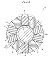
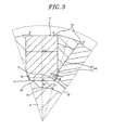
- the rotor 3 is provided on the outer circumferential surface of the shaft 9. As shown in Figs. 2 and 3 , the rotor 3 includes a laminated iron core 10 and a plurality of (ten, in the present embodiment) permanent magnets 11.
- the laminated iron core 10 includes a tubular connecting portion 12 surrounding the shaft 9 and a plurality of (ten, in the present embodiment) magnetic pole portions 13 radially provided as a single body at the radial outer side of the connecting portion 12 in a number corresponding to a pole number.
- the laminated iron core 10 has a structure in which ten magnetic pole portions 13 protrude radially outward from the connecting portion 12 in a radial pattern.
- the laminated iron core 10 has a plurality of groove-like magnet accommodating air gaps 14 formed between the magnetic pole portions 13 (i.e., between the adjoining magnetic pole portions 13) at the radial outer side of the connecting portion 12.
- the magnet accommodating air gaps 14 are formed to penetrate the magnetic pole portions 13 in the axial direction (in the front-rear direction of the drawing sheet in Figs. 2 and 3 ) and are opened radially outward.
- the permanent magnets 11 are arranged within the respective magnet accommodating air gaps 14 (the details will be described later).
- the outer circumferential surface (radial outer surface) of the connecting portion 12 is flat between joint regions C (i.e., between adjoining joint regions "C") joined to the magnetic pole portions 13.
- the connecting portion 12 includes thick sections 15 formed near the respective joint regions C.
- the radial thickness of the thick sections 15 is larger than the radial thickness of other circumferential sections of the connecting portion 12 than the joint regions C. In other words, the radial thickness of the connecting portion 12 is not uniform along the circumferential direction.
- the radial thickness of the connecting portion 12 near the joint regions C i.e., the radial thickness of the thick sections 15
- a radial thickness "T1" of the connecting portion 12 in the joint regions C is larger than a radial thickness "T2" in the middle position "a" between the joint regions C (i.e., between adjoining joint regions C), one of the circumferential positions other than the joint regions C of the connecting portion 12.
- Each of the magnetic pole portions 13 includes a body section 16 having a substantially sector-like shape in a section view; and a plate-like joint section 17 which connects the body section 16 and the connecting portion 12.
- a dimension "L1" of the body section 16 in the direction perpendicular to the radial direction grows smaller radially inward.
- a dimension "L2" of the joint section 17 in the direction perpendicular to the radial direction is substantially constant.
- the body section 16 includes flanges 18 formed at the radial outer end thereof to extend in the circumferential opposite directions.
- the flanges 18 are configured to partially cover the outer surface (radial outer surface) of each of the permanent magnets 11 arranged within the magnet accommodating air gaps 14 so that a portion of the outer surface of each of the permanent magnets 11 can be exposed to the outside.
- the joint section 17 is positioned between taper portions 19 of the permanent magnets 11 (i.e., between the taper portions 19 of the adjoining permanent magnets 11) arranged within the magnet accommodating air gaps 14. The taper portions 19 will be described later.
- Each of the permanent magnets 11 is formed of a ferrite magnet and includes a taper portion 19 formed at the radial inner side thereof. A dimension "L3" of the taper portion 19 in the direction perpendicular to the radial direction grows smaller radially inward.
- the inner surface (radial inner surface) of each of the permanent magnets 11 is flat.
- the outer surfaces of the respective permanent magnets 11 make close contact with the inner surfaces (radial inner surfaces) of the flanges 18 (i.e., the inner circumferential surfaces of the magnet accommodating air gaps 14).
- Each of the permanent magnets 11 is offset radially outward within each of the magnet accommodating air gaps 14 in such a way that a specified gap 20 exists between the inner surface of each of the permanent magnets 11 and the connecting portion 12
- the magnet accommodating air gaps 14 are formed to have a dimension larger than the dimension of the permanent magnets 11.
- the permanent magnets 11 are axially inserted into the magnet accommodating air gaps 14 when the permanent magnets 11 are installed in the magnet accommodating air gaps 14. Since the permanent magnets 11 are provided with the taper portions 19, it becomes possible to insert the permanent magnets 11 into the magnet accommodating air gaps 14 in a radially outwardly offset state.
- each of the permanent magnets 11 is pressed radially outward by a jig.
- the outer surface of each of the permanent magnets 11 is brought into contact with the inner surfaces of the flanges 18 and is adhesively fixed in this state.
- the magnet torque generated by the composite magnetic flux ⁇ d (see Fig. 2 ) obtained by combining the magnetic flux of the laminated iron core 10 and the magnetic flux of the permanent magnets 11 in a direction perpendicular to the shaft 9 is used as the torque of the rotor 3.
- the rotor 3 of the rotary electric machine 1 of the present embodiment includes the laminated iron core 10 having the connecting portion 12 and the ten magnetic pole portions 13 one-piece formed with each other; and the ten permanent magnets 11 arranged between the magnetic pole portions 13 of the laminated iron core 10.
- the permanent magnets 11 are installed within the magnet accommodating air gaps 14 such that the outer surface of each of the permanent magnets 11 makes close contact with the inner surfaces of the flanges 18 and such that a specified gap 20 exists between the inner surface of each of the permanent magnets 11 and the connecting portion 12.
- the permanent magnets 11 are offset radially outward within the magnet accommodating air gaps 14.
- the permanent magnets 11 By arranging the permanent magnets 11 in the outwardly offset state, it is possible to form air gaps (gaps 20) between the permanent magnets 11 and the connecting portion 12, thereby reducing the leaked magnetic flux. Since the leaked magnetic flux can be reduced in this manner, there is no need to form the punched holes for reducing the leaked magnetic flux between the permanent magnets 11. As a result, no restriction is imposed on the radial dimension of the permanent magnets 11 and the dimension L3 of the permanent magnets 11 in the direction perpendicular to the radial direction. The volume of the permanent magnets 11 can be increased without having to increase the diameter of the rotor 3. Accordingly, it is possible to increase the volume of the permanent magnets 11 while reducing the leaked magnetic flux.
- the permanent magnets 11 inexpensive ferrite magnets can be used in place of rear earth magnets such as neodymium magnets or samarium cobalt magnets, while maintaining the performance of the rotary electric machine 1. It is therefore possible to realize the rotary electric machine in an extremely cost-effective manner.
- the present embodiment it is possible to obtain the following effects.
- the outer circumferential surfaces of the magnetic pole portions of the laminated iron core arranged between the permanent magnets should have a constant dimension in the circumferential direction. Therefore, the dimension of the permanent magnets in the direction perpendicular to the radial direction is limited by the magnetic pole portions.
- the magnetic pole portions 13 are configured to include the flanges 18 partially covering the outer surfaces of the permanent magnets 11.
- the provision of the flanges 18 makes it possible to secure the necessary dimension in the circumferential direction of the outer circumferential surfaces of the magnetic pole portions 13. Regardless of the limitation stated above, it is therefore possible to increase the dimension L3 of the permanent magnets 11 in the direction perpendicular to the radial direction.
- the adjoining permanent magnets make contact with each other at the radial inner opposite ends thereof.
- the radial dimension of the permanent magnets and the dimension of the permanent magnets in the direction perpendicular to the radial dimension are limited by the circumferential gap (pole pitch) between the permanent magnets.
- each of the permanent magnets 11 is configured to include the taper portion 19 formed at the radial inner side thereof.
- the dimension L3 of the taper portion 19 in the direction perpendicular to the radial direction grows smaller radially inward.
- the laminated iron core 10 has a structure in which ten magnetic pole portions 13 protrude radially outward from the tubular connecting portion 12. Therefore, it is likely that stresses are concentrated on the joint regions C between the connecting portion 12 and the magnetic pole portions 13.
- the connecting portion 12 includes the thick sections 15 formed near the respective joint regions C of the magnetic pole portions 13 in the circumferential direction.
- the radial thickness of the thick sections 15 is larger than the radial thickness of other circumferential sections of the connecting portion 12 than the joint regions C. This makes it possible to increase the strength of the joint regions C between the connecting portion 12 and the magnetic pole portions 13 on which stresses are likely to concentrate. Accordingly, the laminated iron core 10 can have a structure stable in strength.
- the outer circumferential surface of the connecting portion 12 is flat between the joint regions C joined to the magnetic pole portions 13.
- the connecting portion 12 becomes thick near the joint regions C between the connecting portion 12 and the magnetic pole portions 13. This makes it possible to increase the strength of the joint regions C between the connecting portion 12 and the magnetic pole portions 13 on which stresses are likely to concentrate.
- each of the magnetic pole portions 13 includes the body section 16 and the joint section 17.
- the body section 16 has the flanges 18 at the circumferential opposite sides of the radial outer end thereof.
- the dimension L1 of the body section 16 in the direction perpendicular to the radial direction grows smaller radially inward.
- the joint section 17 is configured to interconnect the body section 16 and the connecting portion 12.
- the dimension L2 of the joint section 17 in the direction perpendicular to the radial direction is substantially constant.
- the joint section 17 is positioned between the taper portions 19 of the permanent magnets 11.
- the present invention is not limited to the embodiment described above but may be modified in many different forms without departing from the spirit and scope of the present invention.
- the magnet accommodating air gaps 14 for accommodating the permanent magnets 11 are formed into an axially-penetrated and radially-outwardly-opened groove shape in the foregoing embodiment, the present invention is not limited thereto.
- a magnet accommodating air gaps 14' for accommodating the permanent magnets 11 may be formed into an axially-penetrated hole shape not opened radially outward.
- the radial outer ends of body sections 16' of the magnetic pole portions 13 i.e., the radial outer ends of the body sections 16' of the adjoining magnetic pole portions 13
- the outer surfaces of the respective permanent magnets 11 make close contact with the inner circumferential surfaces of the magnet accommodating air gaps 14'.
- Each of the permanent magnets 11 is offset radially outward within each of the magnet accommodating air gaps 14' in such a way that a specified gap 20 exists between the inner surface of each of the permanent magnets 11 and the connecting portion 12.
- the magnet accommodating air gaps 14' are formed into a hole shape not opened radially outward, whereby the laminated iron core 10 is one-piece formed through the circumferential joint. Accordingly, as compared with a case where the magnet accommodating air gaps are formed into a radially-outwardly-opened groove shape, it is possible to increase the torsional rigidity of the laminated iron core 10. Moreover, as compared with the case where the magnet accommodating air gaps are formed into the radially-outwardly-opened groove shape, it is possible to increase the bonding area of the permanent magnets 11. This makes it possible to enhance the bonding reliability.
- the present invention is not limited thereto but may be applied to an outer-rotor-type rotary electric machine in which a rotor is arranged outside a stator.
- the present invention is not limited thereto but may be applied to a case where the rotary electric machine is a generator.
Landscapes
- Engineering & Computer Science (AREA)
- Power Engineering (AREA)
- Permanent Field Magnets Of Synchronous Machinery (AREA)
- Iron Core Of Rotating Electric Machines (AREA)
- Permanent Magnet Type Synchronous Machine (AREA)
Applications Claiming Priority (1)
| Application Number | Priority Date | Filing Date | Title |
|---|---|---|---|
| JP2011151637A JP5240593B2 (ja) | 2011-07-08 | 2011-07-08 | 回転電機 |
Publications (1)
| Publication Number | Publication Date |
|---|---|
| EP2544336A2 true EP2544336A2 (de) | 2013-01-09 |
Family
ID=46465112
Family Applications (1)
| Application Number | Title | Priority Date | Filing Date |
|---|---|---|---|
| EP12175054A Withdrawn EP2544336A2 (de) | 2011-07-08 | 2012-07-05 | Rotierende elektrische Maschine |
Country Status (5)
| Country | Link |
|---|---|
| US (1) | US9281723B2 (de) |
| EP (1) | EP2544336A2 (de) |
| JP (1) | JP5240593B2 (de) |
| CN (2) | CN102868245A (de) |
| BR (1) | BR102012016875A2 (de) |
Families Citing this family (16)
| Publication number | Priority date | Publication date | Assignee | Title |
|---|---|---|---|---|
| JP5240593B2 (ja) * | 2011-07-08 | 2013-07-17 | 株式会社安川電機 | 回転電機 |
| FR2982093B1 (fr) * | 2011-10-27 | 2017-11-03 | Valeo Equip Electr Moteur | Rotor de machine electrique tournante et machine electrique tournante comprenant un rotor |
| US9246364B2 (en) | 2012-10-15 | 2016-01-26 | Regal Beloit America, Inc. | Radially embedded permanent magnet rotor and methods thereof |
| JP6151050B2 (ja) * | 2013-03-04 | 2017-06-21 | アイチエレック株式会社 | 回転子および永久磁石電動機 |
| JP6083523B2 (ja) | 2013-05-21 | 2017-02-22 | 日本電産株式会社 | ロータおよびモータ |
| JP6403982B2 (ja) * | 2014-04-30 | 2018-10-10 | マブチモーター株式会社 | ブラシレスモータ |
| FR3022088B1 (fr) * | 2014-06-05 | 2016-06-03 | Valeo Equip Electr Moteur | Rotor a aimants permanents a concentration de flux pour machine electrique tournante |
| TWI556549B (zh) * | 2015-10-05 | 2016-11-01 | 建準電機工業股份有限公司 | 內轉子馬達、內轉子馬達之轉子及其尺寸選用方法 |
| TWI572119B (zh) | 2015-10-16 | 2017-02-21 | 建準電機工業股份有限公司 | 內轉子馬達及其轉子 |
| US10389196B2 (en) * | 2016-03-31 | 2019-08-20 | Nidec Motor Corporation | Spoked rotor with tapered pole segments and tapered ear recesses |
| EP3276794B1 (de) * | 2016-07-29 | 2018-09-19 | Etel S. A.. | Rotor für einen synchronmotor |
| TWI605667B (zh) | 2016-09-01 | 2017-11-11 | 建準電機工業股份有限公司 | 內轉子馬達及其轉子 |
| BR112019027906B1 (pt) * | 2017-06-27 | 2023-11-28 | Syzygy Plasmonics Inc | Sistema reator e método para transformar pelo menos um gás reagente |
| US12176760B2 (en) * | 2019-08-26 | 2024-12-24 | Nidec Corporation | Interior permanent magnet motor |
| JP7395185B2 (ja) * | 2020-06-09 | 2023-12-11 | 公立大学法人秋田県立大学 | 回転電機 |
| CN112615446A (zh) * | 2020-11-18 | 2021-04-06 | 广东威灵电机制造有限公司 | 转子冲片、转子组件和电机 |
Citations (1)
| Publication number | Priority date | Publication date | Assignee | Title |
|---|---|---|---|---|
| JPH0736459U (ja) | 1993-12-20 | 1995-07-04 | 株式会社小糸製作所 | 発光ダイオード |
Family Cites Families (20)
| Publication number | Priority date | Publication date | Assignee | Title |
|---|---|---|---|---|
| JPS5814691Y2 (ja) * | 1977-10-18 | 1983-03-24 | 株式会社安川電機 | 回転電機の界磁 |
| JPS5465309A (en) | 1977-11-02 | 1979-05-25 | Hitachi Ltd | Dc machine commutator riser |
| US4445062A (en) * | 1978-12-26 | 1984-04-24 | The Garrett Corporation | Rotor assembly having anchors with undulating sides |
| US4332079A (en) * | 1978-12-26 | 1982-06-01 | The Garrett Corporation | Method of making rotor rectangularly shaped tongues |
| US4260921A (en) * | 1978-12-26 | 1981-04-07 | The Garrett Corporation | Permanent magnet rotor assembly having rectangularly shaped tongues |
| JPS5959054A (ja) * | 1982-09-27 | 1984-04-04 | Fanuc Ltd | 永久磁石界磁回転子構造 |
| JPS617274U (ja) * | 1984-06-15 | 1986-01-17 | 株式会社安川電機 | 同期電動機のロ−タ磁極 |
| JPH0834016B2 (ja) | 1988-07-28 | 1996-03-29 | チューナー株式会社 | オートリバース方式のテーププレーヤ |
| JPH0237553U (de) * | 1988-08-30 | 1990-03-13 | ||
| JPH0736459Y2 (ja) * | 1990-01-23 | 1995-08-16 | 株式会社安川電機 | 永久磁石界磁形回転子 |
| JPH0736459A (ja) | 1993-07-21 | 1995-02-07 | Roland Corp | 電子楽器のアサイン装置 |
| DE10345417A1 (de) * | 2003-09-30 | 2005-05-12 | Minebea Co Ltd | Rotorköper für einen Elektromotor |
| DE10318624A1 (de) * | 2003-04-24 | 2004-11-25 | Minebea Co., Ltd. | Rotorkörper für einen Elektromotor |
| JP2006115663A (ja) * | 2004-10-18 | 2006-04-27 | Toshiba Corp | 永久磁石回転子 |
| KR100785799B1 (ko) * | 2005-10-14 | 2007-12-13 | 한국전자통신연구원 | 다중 주파수채널 시스템에서 효율적인 스펙트럼 센싱을이용한 채널 할당 방법 |
| JP2009050148A (ja) * | 2007-07-26 | 2009-03-05 | Meidensha Corp | 広範囲定出力永久磁石式モータ |
| EP2201663B1 (de) * | 2007-10-11 | 2016-08-31 | ThyssenKrupp Presta AG | Rotor für elektromotor |
| US8018110B2 (en) * | 2009-04-30 | 2011-09-13 | General Electric Company | High speed internal permanent magnet machine and method of manufacturing the same |
| US7994668B2 (en) * | 2009-05-18 | 2011-08-09 | General Electric Company | Cooling system for rotating machine |
| JP5240593B2 (ja) * | 2011-07-08 | 2013-07-17 | 株式会社安川電機 | 回転電機 |
-
2011
- 2011-07-08 JP JP2011151637A patent/JP5240593B2/ja not_active Expired - Fee Related
-
2012
- 2012-07-03 US US13/541,025 patent/US9281723B2/en not_active Expired - Fee Related
- 2012-07-05 EP EP12175054A patent/EP2544336A2/de not_active Withdrawn
- 2012-07-06 CN CN2012102347050A patent/CN102868245A/zh active Pending
- 2012-07-06 CN CN2012203298786U patent/CN202759303U/zh not_active Expired - Fee Related
- 2012-07-09 BR BRBR102012016875-8A patent/BR102012016875A2/pt not_active IP Right Cessation
Patent Citations (1)
| Publication number | Priority date | Publication date | Assignee | Title |
|---|---|---|---|---|
| JPH0736459U (ja) | 1993-12-20 | 1995-07-04 | 株式会社小糸製作所 | 発光ダイオード |
Also Published As
| Publication number | Publication date |
|---|---|
| BR102012016875A2 (pt) | 2015-03-24 |
| CN102868245A (zh) | 2013-01-09 |
| JP5240593B2 (ja) | 2013-07-17 |
| US20130009505A1 (en) | 2013-01-10 |
| JP2013021776A (ja) | 2013-01-31 |
| US9281723B2 (en) | 2016-03-08 |
| CN202759303U (zh) | 2013-02-27 |
Similar Documents
| Publication | Publication Date | Title |
|---|---|---|
| US9281723B2 (en) | Rotary electric machine with tapered permanent magnet | |
| CN103339832B (zh) | 车辆用永磁铁埋入式旋转电机 | |
| CN104716760B (zh) | 旋转电机 | |
| US8860271B2 (en) | Rotating electric machine | |
| CN102420473A (zh) | 转子 | |
| US20180366996A1 (en) | Brushless motor and stator therefor | |
| US9024498B2 (en) | Rotating electrical machine | |
| JP5656719B2 (ja) | 永久磁石型回転電機及び永久磁石型回転電機の製造方法 | |
| JP5347588B2 (ja) | 埋め込み磁石式モータ | |
| US20180062460A1 (en) | Permanent-magnet-embedded electric motor, blower, and refrigerating air conditioner | |
| US20190140500A1 (en) | Permanent magnet motor | |
| JP2009118629A (ja) | 交流モータ | |
| US12261485B2 (en) | Rotor with permanent magnets having different coercive forces | |
| US10014736B2 (en) | Permanent magnet-embedded motor and rotor thereof | |
| JP6112970B2 (ja) | 永久磁石式回転電機 | |
| JP2013132124A (ja) | 界磁子用コア | |
| JP2014087229A (ja) | 磁石埋込型ロータ | |
| US11901773B2 (en) | Rotating electric machine | |
| JP5918070B2 (ja) | Ipmモータ | |
| JP2012235608A (ja) | 同期電動機 | |
| JP5750995B2 (ja) | 同期電動機 | |
| KR101448649B1 (ko) | 모터 | |
| CN116458033A (zh) | 旋转电机的转子 | |
| JP3671928B2 (ja) | 回転電機のアウターロータ構造 | |
| WO2013111335A1 (ja) | 回転電機 |
Legal Events
| Date | Code | Title | Description |
|---|---|---|---|
| PUAI | Public reference made under article 153(3) epc to a published international application that has entered the european phase |
Free format text: ORIGINAL CODE: 0009012 |
|
| AK | Designated contracting states |
Kind code of ref document: A2 Designated state(s): AL AT BE BG CH CY CZ DE DK EE ES FI FR GB GR HR HU IE IS IT LI LT LU LV MC MK MT NL NO PL PT RO RS SE SI SK SM TR |
|
| AX | Request for extension of the european patent |
Extension state: BA ME |
|
| STAA | Information on the status of an ep patent application or granted ep patent |
Free format text: STATUS: THE APPLICATION HAS BEEN WITHDRAWN |
|
| 18W | Application withdrawn |
Effective date: 20160728 |