EP2543307A1 - Lave-vaisselle, en particulier lave-vaisselle ménager avec au moins un système lumineux passif émettant de la lumière à l'intérieur - Google Patents
Lave-vaisselle, en particulier lave-vaisselle ménager avec au moins un système lumineux passif émettant de la lumière à l'intérieur Download PDFInfo
- Publication number
- EP2543307A1 EP2543307A1 EP12173075A EP12173075A EP2543307A1 EP 2543307 A1 EP2543307 A1 EP 2543307A1 EP 12173075 A EP12173075 A EP 12173075A EP 12173075 A EP12173075 A EP 12173075A EP 2543307 A1 EP2543307 A1 EP 2543307A1
- Authority
- EP
- European Patent Office
- Prior art keywords
- dishwasher
- passive
- light
- door
- illuminant
- Prior art date
- Legal status (The legal status is an assumption and is not a legal conclusion. Google has not performed a legal analysis and makes no representation as to the accuracy of the status listed.)
- Granted
Links
- 239000004033 plastic Substances 0.000 claims abstract description 15
- 229920003023 plastic Polymers 0.000 claims abstract description 15
- 239000000126 substance Substances 0.000 claims abstract description 11
- 238000005286 illumination Methods 0.000 claims abstract description 6
- 239000007787 solid Substances 0.000 claims abstract description 6
- 239000011521 glass Substances 0.000 claims abstract description 4
- 238000005406 washing Methods 0.000 claims description 93
- 239000007921 spray Substances 0.000 claims description 16
- 238000003780 insertion Methods 0.000 claims description 3
- 230000037431 insertion Effects 0.000 claims description 3
- 239000004020 conductor Substances 0.000 abstract 1
- 238000004851 dishwashing Methods 0.000 description 10
- 238000007789 sealing Methods 0.000 description 10
- 230000003287 optical effect Effects 0.000 description 6
- 230000008878 coupling Effects 0.000 description 5
- 238000010168 coupling process Methods 0.000 description 5
- 238000005859 coupling reaction Methods 0.000 description 5
- 230000000694 effects Effects 0.000 description 5
- 239000000463 material Substances 0.000 description 5
- 238000011161 development Methods 0.000 description 3
- 230000018109 developmental process Effects 0.000 description 3
- 230000003993 interaction Effects 0.000 description 3
- 238000005507 spraying Methods 0.000 description 3
- 230000000007 visual effect Effects 0.000 description 3
- 230000008901 benefit Effects 0.000 description 2
- 230000005284 excitation Effects 0.000 description 2
- 238000009434 installation Methods 0.000 description 2
- 239000007788 liquid Substances 0.000 description 2
- 238000004020 luminiscence type Methods 0.000 description 2
- 238000005424 photoluminescence Methods 0.000 description 2
- 230000003014 reinforcing effect Effects 0.000 description 2
- 150000003839 salts Chemical class 0.000 description 2
- XLYOFNOQVPJJNP-UHFFFAOYSA-N water Substances O XLYOFNOQVPJJNP-UHFFFAOYSA-N 0.000 description 2
- 230000004308 accommodation Effects 0.000 description 1
- 230000009471 action Effects 0.000 description 1
- 239000000654 additive Substances 0.000 description 1
- 230000002776 aggregation Effects 0.000 description 1
- 238000004220 aggregation Methods 0.000 description 1
- 230000000712 assembly Effects 0.000 description 1
- 238000000429 assembly Methods 0.000 description 1
- 238000006243 chemical reaction Methods 0.000 description 1
- 238000004140 cleaning Methods 0.000 description 1
- 239000012459 cleaning agent Substances 0.000 description 1
- 239000011248 coating agent Substances 0.000 description 1
- 238000000576 coating method Methods 0.000 description 1
- 239000002131 composite material Substances 0.000 description 1
- 230000001419 dependent effect Effects 0.000 description 1
- 239000003599 detergent Substances 0.000 description 1
- 238000010586 diagram Methods 0.000 description 1
- 230000009977 dual effect Effects 0.000 description 1
- 239000000975 dye Substances 0.000 description 1
- 238000010292 electrical insulation Methods 0.000 description 1
- 238000005516 engineering process Methods 0.000 description 1
- 230000005281 excited state Effects 0.000 description 1
- 230000002349 favourable effect Effects 0.000 description 1
- 239000000835 fiber Substances 0.000 description 1
- GNBHRKFJIUUOQI-UHFFFAOYSA-N fluorescein Chemical compound O1C(=O)C2=CC=CC=C2C21C1=CC=C(O)C=C1OC1=CC(O)=CC=C21 GNBHRKFJIUUOQI-UHFFFAOYSA-N 0.000 description 1
- 239000007850 fluorescent dye Substances 0.000 description 1
- 230000005283 ground state Effects 0.000 description 1
- 230000006872 improvement Effects 0.000 description 1
- 238000001746 injection moulding Methods 0.000 description 1
- 239000013307 optical fiber Substances 0.000 description 1
- 229920003229 poly(methyl methacrylate) Polymers 0.000 description 1
- 239000004926 polymethyl methacrylate Substances 0.000 description 1
- 230000001681 protective effect Effects 0.000 description 1
- 230000005855 radiation Effects 0.000 description 1
- 230000002787 reinforcement Effects 0.000 description 1
- 239000011343 solid material Substances 0.000 description 1
- 239000000243 solution Substances 0.000 description 1
Images


Classifications
-
- A—HUMAN NECESSITIES
- A47—FURNITURE; DOMESTIC ARTICLES OR APPLIANCES; COFFEE MILLS; SPICE MILLS; SUCTION CLEANERS IN GENERAL
- A47L—DOMESTIC WASHING OR CLEANING; SUCTION CLEANERS IN GENERAL
- A47L15/00—Washing or rinsing machines for crockery or tableware
- A47L15/42—Details
- A47L15/4246—Details of the tub
-
- A—HUMAN NECESSITIES
- A47—FURNITURE; DOMESTIC ARTICLES OR APPLIANCES; COFFEE MILLS; SPICE MILLS; SUCTION CLEANERS IN GENERAL
- A47L—DOMESTIC WASHING OR CLEANING; SUCTION CLEANERS IN GENERAL
- A47L15/00—Washing or rinsing machines for crockery or tableware
- A47L15/42—Details
- A47L15/4251—Details of the casing
- A47L15/4257—Details of the loading door
-
- A—HUMAN NECESSITIES
- A47—FURNITURE; DOMESTIC ARTICLES OR APPLIANCES; COFFEE MILLS; SPICE MILLS; SUCTION CLEANERS IN GENERAL
- A47L—DOMESTIC WASHING OR CLEANING; SUCTION CLEANERS IN GENERAL
- A47L15/00—Washing or rinsing machines for crockery or tableware
- A47L15/42—Details
- A47L15/50—Racks ; Baskets
- A47L15/502—Cutlery baskets
Definitions
- the invention relates to a dishwasher, in particular domestic dishwasher, having a loading container having a loading opening, which can be closed by a door.
- Dishwashers are often equipped with lighting that illuminates, for example, the interior of the washing container with the door open, to facilitate the operation, for example, the loading or unloading of the receiving basket, or the recognition of certain functional parts, such as a handle on the receiving basket, by improved lighting conditions , or to improve the visual appearance of the dishwasher with the door open.
- a dishwashing machine is known, which has a receiving device equipped with a lighting device.
- a light source is arranged outside the washing at a location not visible from the outside, the light is transmitted with the aid of a light guide in a arranged in the washing compartment further light guide, from which the light exits again.
- the object of the invention is to propose a dishwasher, in particular a domestic dishwasher, in which an illumination and / or an optical design is achieved in an alternative manner.
- a dishwashing machine of the type mentioned above in that at least one passive light source radiating light as a result of illumination by at least one light source, in particular at least when the door is open, is provided in the interior of the dishwasher.
- a passive illuminant is to be understood to mean a luminous means which does not shine on its own power, such as an LED, but which spectrally changes the light of the light source interacting with it or also radiates it unchanged.
- Reflective material which reflects back light beams incident on it in a preferred direction, in particular in the direction of the light source, also counts in particular for the passive fluorescent lamp.
- the interior of the dishwasher preferably includes that area which is bounded or enclosed by the walls of the washing compartment and the door in its closed end position, including the walls of the washing compartment and the door facing this area.
- the interior of the dishwasher is in particular also still such zones attributable to the user is usually invisible when the door is closed when the dishwasher is used for a user and are visible only when partially and / or completely open the door.
- Such zones associated with the interior of the dishwasher may e.g.
- a zone associated with the interior of the dishwasher may have a depthwise extending, inner-wall-side edge zone between the front edge of the washing compartment and a housing attached thereto, e.g. be inside mounted door seal, the offset at a predetermined distance from the front edge of the washing container away in the depth on the side walls, the ceiling wall, and possibly the bottom wall of the washing compartment is attached.
- a reinforcing or frame element at the upper, front edge, the two lateral front edges, and possibly on lower, front edge of the washing container is mounted on the front and protrudes forward.
- This can advantageously provide a sealing bed for the door seal.
- the zone associated with the interior of the dishwasher is formed by the inner wall-side edge zone region of the reinforcement or frame element between its front edge and the sealing bed with the door seal.
- the door seal portions frame a frontal feed opening of the washing container, behind which, viewed in the depth direction, the spray or wet area of the interior of the washing container lies.
- the one or more passive illuminants in the interior of the dishwashing machine are inside the interior of the washing container, in particular on one or more interior walls and / or on one or more inside the washing compartment accommodated, preferably movable components, and / or on the door, in particular inner wall of the Door, provided.
- surfaces of the inner walls of the washing container and / or functional components in the washing container such as e.g. one or more components of wash baskets such as e.g. Crockery or cutlery partially or completely brought to light and thus for a user of the dishwasher with the door open, especially in their approximately horizontal opening end, improved in a simple way made visible.
- one or more passive lighting means can also be provided outside the washing container in the interior of the dishwasher. This may be, for example, an edge zone of the inner wall of the door outside the wet area of the washing container between the seating area coming into contact with the door seal of the washing container in the closing end position of the door and the outer edge of the inner wall of the door. Additionally or independently thereof, one edge zone of the washing container or of a frame member attached to the front side thereof, which is concealed in the approximately vertical closing end position of the door and runs around the door seal outside the wet region of the washing container, can be equipped with one or more passive lighting elements. As a result, the edge zone can be illuminated partially or continuously around the feed opening of the washing container.
- the one or more passive illuminants in the interior of the dishwasher make it possible in particular to also illuminate areas in the interior of the dishwasher, i. to visualize where an active light source is difficult or impossible to attach.
- movable functional components in the washing container such as e.g. rotatable spray arms, out and in movable receiving baskets, operating parts of feeders, and / or other handling components in a simple way to be made visible.
- an active light source such as e.g. LED or incandescent lamp required that this is laid by an electrical power supply unit, which is housed, for example, in the base support member below the washing compartment, a power line.
- the ambient light which falls on the respective passive illuminant when the door is open may already be sufficient to stimulate it to illuminate and / or focus, i. to reflect with a preferred direction.
- the passive lighting means can also be accommodated in the wet area of the washing container without the need for complex electrical insulation measures and / or spray-water protection measures, as in the case of an electric light source. Because the respective passive lighting means is formed in an advantageous manner largely insensitive to moisture and spray.
- At least one light source is provided as part of the dishwasher, which is arranged in particular in the interior of the dishwasher, preferably outside and / or inside the washing container and / or on the door, in particular inside wall of the door, and in whose light cone the respective passive lighting means directly, or possibly also indirectly, is arranged or positionable.
- the respective light source is arranged and aligned such that an interaction with the one or more passive lighting means in the interior of the dishwasher is effected.
- the dishwashing machine's own light source ensures that one or more passive illuminants having a high degree of freedom in the interior of the dishwasher, preferably on function components accommodated therein, can be attached and illuminated there by the light source in addition to the light source. Even in places with little space or at the door open from the outside difficult to reach places of the interior of the dishwasher, and / or on moving components such as receiving baskets so one or more passive lighting can be readily attached.
- the respective passive illuminant can be made to shine by virtue of the fact that this light beam directly or indirectly incident on it, which is emitted by the light source, in a targeted manner with a preferred direction, such as frontal forward, and reflected / or by this his material for emitting or for the emission of light is excited.
- At least one light source in the interior of the dishwasher is provided outside the wet area of the washing container at its front frame element, in particular at the upper portion of the front frame element, viewed in the depth direction of the dishwasher in front of the door seal of the door, and at least in its light cone a passive lighting in the interior of the dishwasher is arranged or positioned.
- expensive protective measures for spray water protection of the light source are dispensable.
- At least one light source is present in the interior of the dishwasher, in the light cone of which at least one passive illuminant is arranged or positionable.
- this embodiment is no photoconductive cable between the respective light source and the respective passive lighting means required, which extends both the range of applications and the possibilities for optical design in particular of the interior region of the dishwasher, which is also attributable to the inside of the door.
- not all conceivable places for lighting or visual highlighting can be reached in a dishwashing machine with the aid of a light-conducting cable. This is especially true for moving components, such as for crockery and / or cutlery baskets, spray arms, rollers facilitating retraction and extension to a receiving basket and / or the pivotally mounted door.
- connection with a photoconductive cable is usually associated only with increased design and assembly effort, such as a fiber optic cable to lay so that it is not visible and is protected by the prevailing conditions in the dishwasher during dishwashing. This effort is no longer required by the solution according to the invention.
- the light source in particular if it is part of the dishwasher, preferably its interior, a double function, for example, by serving to illuminate a dish rack and also at a remote location by means of their respective illuminated by her passive lighting can cause a luminous effect.
- the respective passive lighting means may expediently be either a separate part fixed to a component of the dishwasher or a component of the component, or may form it in its entirety.
- lamps can be used that are designed to be reflective, such as due to a corresponding surface structure, or due to a coating, in particular with a reflective color unfold their lighting effect.
- passive illuminants are used whose luminous effect is based on the principle of photoluminescence.
- a corresponding substance here exemplified the known fluorescein, placed in an excited state, wherein in the case of fluorescence with virtually no time delay and in the phosphorescence with a time delay, for example, a few minutes, under Emission of fluorescent light back in returns to the ground state.
- the advantage of the passive luminescent means based on photoluminescence over reflective passive luminescent means is that with regard to the spatial design of the respective passive element, there is a greater latitude, since, for example, the dependence of the incidence and the angle of reflection of the light on reflective elements is largely irrelevant and therefore not to be considered.
- the photoluminescent substance can in principle have any state of aggregation, that is to say solid, liquid or gaseous.
- the passive illuminant may comprise a substance receiving container with a transparent wall.
- the passive illuminant may also be coated with a photoluminescent ink or other photoluminescent material layer.
- passive fluorescent lamps are preferably used which consist at least partially of a transparent, solid material containing the photoluminescent substance, in particular of a glass or plastic, for example acrylic glass.
- a transparent, solid material containing the photoluminescent substance in particular of a glass or plastic, for example acrylic glass.
- Such solids can be easily produced in almost any shape and are, which is especially true for plastic, easily deformed and machined.
- passive illuminants those which comprise or consist of a light guide which has at least one light entry surface are also still considered.
- the at least one light entry surface is expediently arranged or positionable so that it is illuminated by the light source.
- the light entry surface may optionally be preceded by a collecting optical element, or the light entry surface is itself part of such an element, which may for example have the shape of a parabolic mirror.
- a particularly advantageous embodiment provides that the light source and passive lighting means are arranged to be movable relative to each other.
- a passive illuminant can be arranged on a receiving basket, ie movable, and at least one light source can be arranged on a component, in particular stationary, and / or the door of the dishwasher.
- the door can also be considered as a stationary component, and that is when it is open.
- the light source is, for example, above the receiving basket, for example outside the wet space of the washing container at a position located above a receiving basket, for example at the upper edge of the washing container, in particular a front frame element mounted there before the sealing bed, which is a seal for liquid-tight closing of the door in its Sch formatdposition, arranged and - at least also - directed downwards, so that at least a portion of its cone of light detects the respective passive illuminant on the receiving basket in a height position below the light source, ie hits.
- one or more light sources on the underside of the upper portion of this frame or reinforcing element are provided in particular such that they are substantially invisible to a user standing in front of the dishwasher at the installation site, and thus do not dazzle the user in the on state.
- the passive illuminant attached to the receiving basket changes according to a further advantageous embodiment of the invention, its relative position to the light source. So that at least one region of the passive illuminant emits light in each depth position of the receiving basket, which can be displaced into different depth positions in the depth direction of the washing container, it expediently extends in the direction of movement of the receiving basket or in the depth direction of the dishwasher.
- the passive illuminant thus illuminates at different longitudinal sections.
- an illuminated area of the passive illuminant moves along the moving path of the receiving basket, such as when moving out front to back and when retracting the receiving basket in the reverse direction.
- the respective passive illuminant can in particular also be configured as an optical waveguide, ie it is designed such that the coupled or photoluminescent light is passed on within the passive illuminant, so that even areas which are not acted upon or illuminated directly by the light cone of the light source, at least to some extent shine.
- a passive illuminant embodied as a light guide or of a passive illuminant containing it
- light coupling during the retraction and extension movement of the receiving basket is ensured by having a light entry surface extending in the direction of movement or a plurality of light entry surfaces spaced apart in said direction, so that at different points or respectively In different depth positions of the receiving basket, which can be displaced in different depth positions in the depth direction of the washing container, light can be introduced into the passive lighting means.
- the passive illuminant is simultaneously a component or a functional part of the dishwasher or at least one - preferably functionally essential - element of such a part.
- a design is simple, e.g. with 2-component injection molding technology, feasible.
- this reduces the assembly effort that eliminates the need to fix a separate passive lighting element on a component of the dishwasher.
- Particularly advantageous is a measure of the type in question in functional elements of the receiving basket, in particular in a existing there, for holding items to be washed holding element, such as a hinged basket row or a serving for receiving cutlery insert a cutlery basket such. a cutlery drawer.
- the baskets for e.g. Crockery and / or cutlery form a central and functionally essential area of the dishwasher, which is subjected to a particularly critical consideration by the user.
- the categorization of cutlery and / or crockery is associated with a certain skill, so that supporting lightheads may be attached to one or more functional components of the cassettes, e.g. their holding elements or holding structures for receiving and holding crockery and / or cutlery for an improvement of the lighting conditions are advantageous.
- Another essential functional component is a spray arm present in the washing container. If a receiving basket located below the spray arm is loaded too high, the spray arm touches the wash ware or is prevented from rotating by it. Again, it makes sense if the spray arm is at least partially formed by a passive lighting or provided with a passive lighting to make him and his height position easily recognizable.
- the front-side hand or operating handles on the receiving baskets can each be provided with a passive lighting means to the respective user signal that the baskets can be pulled out of the rinsing container and pushed in.
- attachments preferably if they are made of plastic, in the receiving baskets, such as bearings for foldable folding prong rows or in different height positions and / or inclinations movable Etageren made recognizable.
- movable components in the interior of the dishwasher can be visually highlighted with the help of passive lighting in terms of their respective function, in particular mobility and / or variability, by lighting.
- the movable lid or flaps of a detergent and / or rinse aid addition which is mounted in the interior of the dishwasher, such as on the treatment room of the washing container facing inside of the door, each be provided with a passive lighting.
- the operating part of a salt addition device which is provided, for example, below the bottom of the washing container in a base support assembly of the dishwasher, can be expediently identified with a passive illuminant.
- Passive illuminants can therefore not only on a receiving basket, but generally at any point in the interior of the dishwasher, inside and outside the washing and / or on or in the door in any form, such as strip-shaped films or plates, for example on a wall , Preferably the bottom of the washing and / or at one of the loading opening bordering area, are arranged.
- the position of a light source cooperating with a passive light source is basically arbitrary, provided that its cone of light hits the passive illuminant.
- the respective light source is preferably part of the dishwasher, which is arranged in particular outside and / or inside the washing container, and / or on the door, preferably the inner wall of the door, and in whose light cone the respective passive lighting means is arranged or positionable. This ensures that the respective passive lighting means can be lit by a dishwashing machine-own light source, ie largely independent of the ambient light at the respective installation location of the dishwasher.
- the respective light source is outside the rinse container, i.
- the wet area of the washing container which is acted upon by the spraying system with cleaning liquid and is separated from the environment by the door-cooperating door seal, is arranged outside of the environment.
- the light source can be arranged at the upper edge, in particular above the upper edge of the washing container.
- at least one light source in the interior of the dishwasher can be arranged outside the wet area of the washing container on its front frame element, in particular on the upper portion of this front frame element (in front view) in front of a seal provided for the door, which is held in a sealing bed of the frame element.
- At least one light source within the washing container may be fixed to a wall of the washing container, for example on a side or rear wall. Additionally or independently thereof, at least one light source may possibly also be arranged on the inside of the door (facing the interior of the washing compartment in the closing end position of the door).
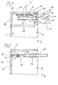
- Fig. 1 and 2 each show a household dishwasher 1, which comprises a front loading opening 2 having a washing container 3.
- the rinsing container 3 may be partially or completely surrounded by an outer housing and / or other attachments in the region of its walls.
- an outer housing KO additionally indicated by dash-dotted lines.
- a spraying device for example in the form of one or more spray arms 4 (FIG. Fig. 4 ) arranged.
- the loading opening 2 can be closed by a door 5 hinged to the front of the dishwasher.
- the rinse tank 3 has to offset its front edge in the depth direction into the interior of the washing container offset a strip or line-shaped seal DB in a sealing bed on its two side walls 10, its top wall 14, and possibly bottom wall 11.
- the spanned by the seal DB, thought Laying plane thus defines the loading opening 2 of the washing container 3, which is closed by the inner wall 51 of the door in its approximately vertical final closing position.
- the area between the seal DB provided for the liquid-tight closure of the door and the front edge of the washing container 3 (viewed in the depth direction) lies outside the wet area of the washing container and is advantageous for the favorable accommodation of one or more light sources such as LEDs and / or passive lighting means available.
- At least one light source is accommodated in the closing end position of the door in the interior of the dishwasher and is arranged or positionable outside the wet area of the washing compartment.
- one or more light sources on a front frame element such.
- DB and thus outside the wet area of the interior of the washing container are arranged or positioned so that the respective passive light source in the interior of the dishwasher for emitting light is stimulated or stimulated in the light cone of the respective light source and / or incident light rays are reflected in a preferred direction to the front ,
- the respective passive illuminant may e.g.
- the one or more light sources e.g. LEDs in the largely dry area before the sealing bed DB with the door seal of the washing container, the light sources are also largely electrically safe housed inside the dishwasher.
- one or more light sources 9a are attached to the upper portion of the frame element RE of the washing container 3 and their respective light cone is directed substantially from top to bottom.
- a passive lighting means 6a which is provided on the front side such as on a front handle and / or inside the respective receiving basket 7 such as an upper basket or lower basket, in a plane below the light source (s) 9a, ie is arranged in a lower height position relative to the light source or sources 9a, and from the washing container 3 is partially or completely moved out, be brought to a user for illuminating or lighting.
- the parking position for a lower basket 7 on the inner wall surface 51 of the door 5 can be made recognizable to a user and animated to extend the lower basket 7 for loading or unloading on the inner wall surface 51 of the door 5 in its approximately horizontal ⁇ Stammsendposition.
- the one or more light sources 9a are attached to the underside of the upper portion of the frontally projecting frame element RE of the washing container 3, for a user standing in front of the dishwasher, a largely low-glare or glare-free illumination of the area below the one or more light sources 9a ensured become.
- passive lighting means are provided, which, as will be explained below, at various points, for example on an inner wall such as side wall 10 and / or bottom wall 11 of the washing compartment 2, the door 5 , and / or at least one in the depth direction, preferably horizontally extendable and retractable receiving basket 7, in particular dish rack and / or a retractable and extendable cutlery drawer or the like, etc. may be arranged.
- the passive illuminants are each positioned so that they are acted upon by the light cone such as 8 at least one light source such as 9a or by the light emitted by the light source.
- the respective light source may preferably be arranged within the washing container 2, wherein the side walls 10, the rear wall 13 and / or the top wall 14 come into question.
- a passive illuminant it is also possible to use the light of a light source arranged outside the dishwasher, for example the light of a kitchen lamp or daylight.
- the following description refers primarily to the embodiment with arranged within the dishwasher light source, but with comments on Design and arrangement of passive lighting mutatis mutandis also apply to the embodiment with external light source.
- Passive illuminants in addition to reflective elements or elements which are coated in a reflective manner, include passive illuminants which contain a photoluminescent substance. It is conceivable that such a substance is applied to a surface area of the washing container 2, the door 5 and / or a component such as a receiving basket 7. Another possibility is that the passive illuminant is at least partially formed of a translucent solid such as glass, plastic or a composite of said materials. Such passive lighting or, above all, such plastics are known, so that no further explanation is needed.
- the one or more passive lighting means can not only be attached as a separate part to a component, for example a spray arm 4 or a receiving basket 7, but form a part of the component or component as a whole.
- a component for example a spray arm 4 or a receiving basket 7, but form a part of the component or component as a whole.
- spraying arm 4 shown in the form of strips may be mounted as passive lighting means 6j. It is also conceivable, however, that the entire spray arm 4 or at least a part thereof is formed from a passive illuminant, for example a photoluminescent plastic.
- optical fibers come into question, that is to say elements made of plastic, which are designed in such a way that light of the light source, such as 9a, entering via a light entry surface 16 (see FIG FIG. 4 ) is forwarded by total reflection within the passive illuminant, so that it exits again at a light exit surface 17 remote from the light entry surface 16 or also at other surfaces extending, for example, in the propagation direction of the light.
- LISA plastics - light-collecting plastics - can be used.
- plastics contain a fluorescent dye, but they are dimensioned so that the fluorescent light is forwarded by total reflection, but in addition a certain part of the fluorescent light exits on all surfaces of the passive illuminant, such as 6e, which extend along the propagation direction of the light.
- the dishwashing machine 1 here comprises an upper and a lower dish rack 7.
- the front area thereof is provided with a passive lighting means 6a positioned at its upper edge and designed in the form of a strip extending essentially in the width direction of the washing compartment.
- the passively luminous band on the respective dish rack preferably runs substantially parallel to a plane extending in the height and width direction of the washing compartment. It can act as a front panel or front panel for the respective crockery basket.
- a partial section, in particular the middle region of the frontal section of the strap can be designed as a handle, preferably a grip recess.
- Light sources 9a can also be used to illuminate the interior of the washing container 2. They are generally designed so that they form a downward and obliquely inward (into the interior 31 of the washing container 3) directed light cone 8 (indicated by the arrows 19 in Fig. 4 ). In this way it is ensured that when retracted receiving basket 7, as in Fig.
- both front-side passive lighting means 6a of the receiving baskets 7 are exposed to light and excited to shine.
- light sources such as 9b, 9d may additionally or independently of the upper-side light sources 9a also be positioned at other locations, for example at a point from which the receiving baskets 7 can be illuminated from the side.
- the light source 9b can be arranged inside or outside the washing container 2 and at one of its side walls 10 or at a lateral position of the dishwasher machine body.
- the light source 9b, and possibly also the light sources 9a positioned above the upper receiving basket 7, can be aligned such that they also apply light to areas of the door, for example lateral areas 20, so that passive light means 6b, 6c arranged there, for example likewise strip-shaped, adjoin the light Lights are excited.
- the passive lighting means 6c are with the door closed 5 within the washing compartment 2 or in the wet area of the Dishwasher 1 is arranged, that is, in the area which is acted upon by the closed door of a present in the washing 3 spray system, for example, the above-mentioned spray arm 4.
- the passive lighting means 6b are arranged outside the wet area, ie they are located with the door closed to the right or left outside of a present on the inside of the door 5 sealing area 23, at which with the door closed, the door seal DB, in the FIG. 1 only schematically indicated, is present.
- a single strip-shaped passive illuminant such as only 6b or only 6c per side area of the door may be sufficient for lighting.
- the lateral passive lighting means such as 6b, 6c, extend on the inner wall of the door substantially along their entire extent in the depth direction of the washing compartment. This corresponds in the vertical closing position of the door about its height extension.
- Passive Illuminants 61 and / or 6m, the z. B. in strip form in the depth direction of the washing container 3, may be provided.
- These passive illuminants 61, 6m can also be illuminated by means of the light source (s) 9a, 9b.
- Such further passive illuminants 61 on the side walls 10 of the washing container are in the FIG. 1 indicated by dash-dotted lines.
- the passive illuminants 6m at the bottom 11 of the washing compartment are in the FIG. 2 also shown in dash-dotted lines.
- a light source 9d is additionally shown in dash-dot lines in the inner door 51. It is arranged approximately centrally with respect to the width of the door. It emits a cone of light 8 in the direction of the passive illuminant 6a on the front side of the two stacked baskets 7 arranged one above the other.
- Fig. 2 shows an example of a passive lighting means 6d, which serves as a functional element for a basket designed as a cutlery drawer or a cutlery basket 7 'basket above the one or more dishes basket or baskets such as 7.
- the passive lighting means 6d forms a light-conducting receiving strip 24 for cutlery.
- two such receiving strips 24 in the width direction of the dishwasher 1 are arranged so that they are acted upon by the light cone 8 of above the cutlery basket 7 'arranged two light sources 9a.
- the upper-side light entry surface 16 (see FIG. 4 ) of the respective receiving bar 24 thus moves with the sliding movement of the cutlery drawer 7 '.
- the respective receiving strip 24 preferably extends along the depth extent of the cutlery drawer 7 '. Depending on the depth position of the cutlery drawer 7 ', another area of the receiving strips 24 illuminates.
- the receiving strips 24, which preferably extend over the entire depth of the cutlery drawer 7', are, for example, as in FIG Fig. 2a designed. They comprise a strip-shaped base part 25, on which upwardly extending holding elements 27 are formed in a row, which release between each serving for the insertion of cutlery interstices 26.
- the receiving strip 24 or the passive illuminant 6d is either formed as a separate part, which is fixed to the cutlery drawer or on the cutlery basket 7 ', or it is an integral component of the cutlery basket 7', for example molded on this.
- the passive illuminant 6d can act not only light-conducting, but additionally or independently thereof in particular luminescent.
- the passive illuminant 6d embodied as a receiving strip 24 or else a differently designed passive illuminant is embodied as an optical waveguide it can be particularly expedient if a light source 9c is preferably attached to the rear wall 13 of the rinsing container 3 (FIG. Fig. 5 ) is arranged.
- the respective light source 9 c is located at a height level, which is about the height level of the trajectory of their respective assigned receiving basket 7, in particular at their respective assigned cutlery drawer 7 ', existing passive lighting means, such as a receiving bar 24 of the type described above, located.
- This embodiment ensures that the passive illuminant in each depth position of the respective receiving basket 7, 7 'is acted upon by the light cone 8 of the rear light source 9c, so that light can be coupled from the rear to the front.
- the end face of the passive illuminant 6d facing the rear wall 13 can serve as a light coupling surface 16.
- a light coupling element 28 comprising a light entry surface to be arranged at the rear end of the passive illuminant 6d.
- the light coupling element 28 is, for example, an element designed in the manner of a parabolic mirror, the mirror surface of which Light entrance surface 16 forms.
- the beam path of a light beam is in Fig. 5 indicated by the arrow 29.
- a passive illuminant 6e is shown that, for example, similar to the receiving strip 24 described above can be configured and arranged on the respective receiving basket, but it is a luminescent, in particular fluorescent effective passive lighting.
- a receiving basket 7 or 7 ' is moved out of the washing container 3 and back into it, a region 30 of the light source 9a facing the light source 9a of the passive illuminating means 6e is acted upon by the light cone 8 and thereby illuminated.
- the passive illuminant 6a is designed so that it is responsible for the resulting luminescence radiation, which in Fig.
- FIG. 3 shows a receiving basket 7, the side guide rollers 35 has. These guide rollers 35, optionally also holding them, for example, in the form of a extending in the depth direction of the receiving basket 7 strip carrier 36 may be provided with a passive lighting means or even form such a passive lighting means 6f and 6g.
- a centrally arranged plate 37 which forms a bottom region of the receiving basket 7, of a luminescent plastic can be attached to the receiving basket 7, for example. The plate is pulled upwards at its front end, forming a visible light exit surface 17 when the door is open.
- the side edges 38 of the plate 37 can serve, in which case a gap 40 located between the lateral edge 38 and a basket wire 39 extending in the depth direction of the receiving basket 7 can be illuminated.
- the passive illuminant 6h formed as a plate 37 may have a light entry surface 16, wherein in the present case of a at the rear end of the plate 37 upwardly projecting leg 43 and that is arranged on the rear side 13 of the washing container 3 side facing.
- the plate 37 is penetrated by a central opening 41, wherein the opening 41 delimiting edges 42 of the plate 37 also serve as light exit surfaces 17.
- a further basket element which is designed as passive illuminant 6i or comprises such a luminous means.
- This is a row of basket stiles 44 extending in the depth direction of the receiving basket 7 and projecting upwards from, for example, a wire-shaped base support 45 extending in the depth direction of the receiving basket 7.
- the individual Korbstacheln 44 and the base support 45 are formed by a light guide of the type described above or contain a light guide, wherein at the free ends of the Korbstacheln 44 light exit surfaces 17 are arranged.
- a further passive lighting means 6k is shown, which is arranged on the rear side of the receiving basket 7, for example in its bottom area, and is, for example, a strip of material extending over the entire width of the receiving basket 7.
- the irradiation of light can, for example, via a arranged on the rear wall 13 of the washing container 3 light source 9c ( Fig. 5 ) respectively.
- a light entry surface (not shown) may be present, via which, for example, light from the light source 9c can be coupled in.
- a passive lighting element 61 is finally still Fig. 4 refer to. It is arranged on an inner wall, such as the respective side wall 10 of the washing container 3, and configured, for example, as a strip or strip extending in the depth direction.
Landscapes
- Washing And Drying Of Tableware (AREA)
Priority Applications (2)
| Application Number | Priority Date | Filing Date | Title |
|---|---|---|---|
| PL12173075T PL2543307T3 (pl) | 2011-07-06 | 2012-06-22 | Zmywarka do naczyń, w szczególności zmywarka do naczyń gospodarstwa domowego, z co najmniej jednym emitującym światło pasywnym środkiem oświetleniowym w przestrzeni wewnętrznej |
| EP20130153308 EP2596737B1 (fr) | 2011-07-06 | 2012-06-22 | Lave-vaisselle, en particulier lave-vaisselle ménager avec au moins un système lumineux passif émettant de la lumière à l'intérieur |
Applications Claiming Priority (2)
| Application Number | Priority Date | Filing Date | Title |
|---|---|---|---|
| DE102011078761 | 2011-07-06 | ||
| DE102011084461A DE102011084461A1 (de) | 2011-07-06 | 2011-10-13 | Geschirrspülmaschine, insbesondere Haushaltsgeschirrspülmaschine, mit mindestens einem lichtabstrahlenden Passivleuchtmittel im Innenraum |
Related Child Applications (2)
| Application Number | Title | Priority Date | Filing Date |
|---|---|---|---|
| EP20130153308 Division EP2596737B1 (fr) | 2011-07-06 | 2012-06-22 | Lave-vaisselle, en particulier lave-vaisselle ménager avec au moins un système lumineux passif émettant de la lumière à l'intérieur |
| EP20130153308 Division-Into EP2596737B1 (fr) | 2011-07-06 | 2012-06-22 | Lave-vaisselle, en particulier lave-vaisselle ménager avec au moins un système lumineux passif émettant de la lumière à l'intérieur |
Publications (2)
| Publication Number | Publication Date |
|---|---|
| EP2543307A1 true EP2543307A1 (fr) | 2013-01-09 |
| EP2543307B1 EP2543307B1 (fr) | 2019-02-27 |
Family
ID=46465046
Family Applications (2)
| Application Number | Title | Priority Date | Filing Date |
|---|---|---|---|
| EP12173075.8A Active EP2543307B1 (fr) | 2011-07-06 | 2012-06-22 | Lave-vaisselle, en particulier lave-vaisselle ménager avec au moins un système lumineux passif émettant de la lumière à l'intérieur |
| EP20130153308 Active EP2596737B1 (fr) | 2011-07-06 | 2012-06-22 | Lave-vaisselle, en particulier lave-vaisselle ménager avec au moins un système lumineux passif émettant de la lumière à l'intérieur |
Family Applications After (1)
| Application Number | Title | Priority Date | Filing Date |
|---|---|---|---|
| EP20130153308 Active EP2596737B1 (fr) | 2011-07-06 | 2012-06-22 | Lave-vaisselle, en particulier lave-vaisselle ménager avec au moins un système lumineux passif émettant de la lumière à l'intérieur |
Country Status (3)
| Country | Link |
|---|---|
| EP (2) | EP2543307B1 (fr) |
| DE (1) | DE102011084461A1 (fr) |
| PL (1) | PL2543307T3 (fr) |
Cited By (8)
| Publication number | Priority date | Publication date | Assignee | Title |
|---|---|---|---|---|
| WO2014173749A1 (fr) * | 2013-04-23 | 2014-10-30 | BSH Bosch und Siemens Hausgeräte GmbH | Lave-vaisselle doté d'un indicateur optique associé à au moins un composant fonctionnel |
| WO2014180814A1 (fr) * | 2013-05-07 | 2014-11-13 | Meiko Maschinenbau Gmbh & Co. Kg | Dispositif de nettoyage doté d'une poignée de porte éclairée |
| EP2803311A1 (fr) * | 2013-05-16 | 2014-11-19 | Whirlpool Corporation | Lave-vaisselle à éclairage intégré |
| EP2898809A1 (fr) * | 2014-01-27 | 2015-07-29 | Whirlpool Corporation | Lave-vaisselle |
| CN106073679A (zh) * | 2016-08-01 | 2016-11-09 | 珠海格力电器股份有限公司 | 洗碗机照明系统及洗碗机 |
| USD784633S1 (en) | 2014-01-27 | 2017-04-18 | Whirlpool Corporation | Light for dishwasher |
| CN109247896B (zh) * | 2017-07-14 | 2021-06-25 | 青岛海尔洗碗机有限公司 | 一种洗碗机门体导流装置及洗碗机 |
| US11229344B2 (en) * | 2017-08-22 | 2022-01-25 | Whirlpool Corporation | Light source for a dishwasher |
Families Citing this family (3)
| Publication number | Priority date | Publication date | Assignee | Title |
|---|---|---|---|---|
| BR102014013430A2 (pt) * | 2014-06-03 | 2015-12-29 | Whirlpool Sa | sistema de iluminação integrado para aparelhos eletrodomésticos, e aparelho eletrodoméstico provido do referido sistema de iluminação |
| DE102014213418A1 (de) * | 2014-07-10 | 2016-01-14 | BSH Hausgeräte GmbH | Haushaltsgerät mit einer nach vorne ausfahrbaren Einrichtung zur Guthalterung |
| DE102014220245B4 (de) | 2014-10-07 | 2021-09-30 | BSH Hausgeräte GmbH | Geschirrspülmaschine mit einer Beleuchtung |
Citations (5)
| Publication number | Priority date | Publication date | Assignee | Title |
|---|---|---|---|---|
| US5836669A (en) | 1996-01-17 | 1998-11-17 | Troy Investments, Inc. | Remote illumination and light apportionment in appliances |
| WO2006042819A1 (fr) * | 2004-10-20 | 2006-04-27 | BSH Bosch und Siemens Hausgeräte GmbH | Dispositif d'eclairage d'un appareil menager guidant de l'eau |
| DE102010015849B3 (de) | 2010-03-08 | 2011-04-07 | Miele & Cie. Kg | Geschirrspüler |
| EP2366323A1 (fr) * | 2010-03-18 | 2011-09-21 | Miele & Cie. KG | Lave-vaisselle doté d'un dispositif d'éclairage |
| EP2394557A2 (fr) * | 2010-03-18 | 2011-12-14 | Miele & Cie. KG | Lave-vaisselle doté d'un système d'éclairage |
Family Cites Families (1)
| Publication number | Priority date | Publication date | Assignee | Title |
|---|---|---|---|---|
| ES2253628T3 (es) * | 2003-11-21 | 2006-06-01 | Electrolux Home Products Corporation N.V. | Maquina lavavajillas de tipo domestico con indicadores luminosos mejorados. |
-
2011
- 2011-10-13 DE DE102011084461A patent/DE102011084461A1/de not_active Withdrawn
-
2012
- 2012-06-22 EP EP12173075.8A patent/EP2543307B1/fr active Active
- 2012-06-22 EP EP20130153308 patent/EP2596737B1/fr active Active
- 2012-06-22 PL PL12173075T patent/PL2543307T3/pl unknown
Patent Citations (5)
| Publication number | Priority date | Publication date | Assignee | Title |
|---|---|---|---|---|
| US5836669A (en) | 1996-01-17 | 1998-11-17 | Troy Investments, Inc. | Remote illumination and light apportionment in appliances |
| WO2006042819A1 (fr) * | 2004-10-20 | 2006-04-27 | BSH Bosch und Siemens Hausgeräte GmbH | Dispositif d'eclairage d'un appareil menager guidant de l'eau |
| DE102010015849B3 (de) | 2010-03-08 | 2011-04-07 | Miele & Cie. Kg | Geschirrspüler |
| EP2366323A1 (fr) * | 2010-03-18 | 2011-09-21 | Miele & Cie. KG | Lave-vaisselle doté d'un dispositif d'éclairage |
| EP2394557A2 (fr) * | 2010-03-18 | 2011-12-14 | Miele & Cie. KG | Lave-vaisselle doté d'un système d'éclairage |
Cited By (20)
| Publication number | Priority date | Publication date | Assignee | Title |
|---|---|---|---|---|
| EP3241478A1 (fr) * | 2013-04-23 | 2017-11-08 | BSH Hausgeräte GmbH | Lave-vaiselle avec au moins un indicateur optique assigné à un composant fonctionel |
| EP3446615A1 (fr) * | 2013-04-23 | 2019-02-27 | BSH Hausgeräte GmbH | Lave-vaisselle comprenant au moins un affichage optique associé à un composant fonctionnel |
| CN105142484A (zh) * | 2013-04-23 | 2015-12-09 | Bsh家用电器有限公司 | 具有至少一个配属于功能构件的光学显示的洗碗机 |
| WO2014173749A1 (fr) * | 2013-04-23 | 2014-10-30 | BSH Bosch und Siemens Hausgeräte GmbH | Lave-vaisselle doté d'un indicateur optique associé à au moins un composant fonctionnel |
| WO2014180814A1 (fr) * | 2013-05-07 | 2014-11-13 | Meiko Maschinenbau Gmbh & Co. Kg | Dispositif de nettoyage doté d'une poignée de porte éclairée |
| EP2994029B1 (fr) | 2013-05-07 | 2018-09-26 | MEIKO Maschinenbau GmbH & Co. KG | Dispositif de nettoyage doté d'une poignée de porte éclairée |
| US10080476B2 (en) | 2013-05-07 | 2018-09-25 | Meiko Maschinenbau Gmbh & Co. Kg | Cleaning apparatus with illuminated door handle |
| US10022036B2 (en) | 2013-05-16 | 2018-07-17 | Whirlpool Corporation | Dishwasher with integrated lighting |
| EP2803311A1 (fr) * | 2013-05-16 | 2014-11-19 | Whirlpool Corporation | Lave-vaisselle à éclairage intégré |
| US10390682B2 (en) | 2013-05-16 | 2019-08-27 | Whirlpool Corporation | Dishwasher with integrated lighting |
| USD784633S1 (en) | 2014-01-27 | 2017-04-18 | Whirlpool Corporation | Light for dishwasher |
| US9445706B2 (en) * | 2014-01-27 | 2016-09-20 | Whirlpool Corporation | Dishwasher |
| US20150208897A1 (en) * | 2014-01-27 | 2015-07-30 | Whirlpool Corporation | Dishwasher |
| EP2898809A1 (fr) * | 2014-01-27 | 2015-07-29 | Whirlpool Corporation | Lave-vaisselle |
| USD866884S1 (en) | 2014-01-27 | 2019-11-12 | Whirlpool Corporation | Light for dishwasher |
| USD959066S1 (en) | 2014-01-27 | 2022-07-26 | Whirlpool Corporation | Light for dishwasher |
| CN106073679A (zh) * | 2016-08-01 | 2016-11-09 | 珠海格力电器股份有限公司 | 洗碗机照明系统及洗碗机 |
| CN106073679B (zh) * | 2016-08-01 | 2018-11-16 | 珠海格力电器股份有限公司 | 洗碗机照明系统及洗碗机 |
| CN109247896B (zh) * | 2017-07-14 | 2021-06-25 | 青岛海尔洗碗机有限公司 | 一种洗碗机门体导流装置及洗碗机 |
| US11229344B2 (en) * | 2017-08-22 | 2022-01-25 | Whirlpool Corporation | Light source for a dishwasher |
Also Published As
| Publication number | Publication date |
|---|---|
| EP2596737B1 (fr) | 2015-05-20 |
| DE102011084461A1 (de) | 2013-01-10 |
| PL2543307T3 (pl) | 2019-08-30 |
| EP2596737A1 (fr) | 2013-05-29 |
| EP2543307B1 (fr) | 2019-02-27 |
Similar Documents
| Publication | Publication Date | Title |
|---|---|---|
| EP2596737B1 (fr) | Lave-vaisselle, en particulier lave-vaisselle ménager avec au moins un système lumineux passif émettant de la lumière à l'intérieur | |
| EP2765896B1 (fr) | Lave-vaisselle pourvu d'au moins une source de lumière commandée en fonction de la position d'un panier de réception mobile | |
| EP2401950B1 (fr) | Dispositif d'éclairage pour un lave-vaisselle | |
| EP2364635B1 (fr) | Lave-vaisselle avec des moyens d' éclairage | |
| EP2394557B1 (fr) | Lave-vaisselle doté d'un système d'éclairage | |
| DE102011122897A1 (de) | Geschirrspülmaschine mit wenigstens einem am Spülbehälter beweglich gelagerten Bauteil wenigstens aufweisend einen Lichtleiter | |
| DE102005047915A1 (de) | Haushaltsgerät, insbesondere Einbau-Haushaltsgerät mit einer steuerbaren Betriebsanzeige | |
| EP3424364B1 (fr) | Meuble cubique | |
| DE102013206869A1 (de) | Geschirrspülmaschine mit wenigstens einem von einem Leuchtflächenelement und diesem beigeordneten Flächenelement überdeckten Durchbruch in mindestens einer Wand ihres Spülbehälters | |
| AT10559U1 (de) | Schublade mit lichtdurchlassiger wand | |
| DE102010003355A1 (de) | Geschirrspülmaschine | |
| DE202010001579U1 (de) | Beleuchtungsvorrichtung für ein bewegliches Möbelelement sowie Möbelelement | |
| DE202014103896U1 (de) | Spiegelschranktür und Spiegelschrank mit einer solchen Tür | |
| DE102014220245B4 (de) | Geschirrspülmaschine mit einer Beleuchtung | |
| DE102016222486A1 (de) | Getränkedispenser und Kältegerät mit Getränkedispenser | |
| EP2465407A2 (fr) | Lave-vaisselle | |
| DE102011123045B3 (de) | Geschirrspülmaschine mit wenigstens einem am Spülbehälter beweglich gelagerten Bauteil wenigstens aufweisend einen Lichtleiter | |
| DE102010000150B3 (de) | Ein- oder unterbaufähiges Haushaltgerät | |
| EP3599965B1 (fr) | Lave-vaisselle comprenant au moins une arrivée d'eau | |
| DE102023201625A1 (de) | Geschirrspülmaschine mit einem Türgriff und zumindest einem Leuchtelement | |
| EP2896344A1 (fr) | Lave-vaisselle | |
| DE102011078762A1 (de) | Geschirrspülmaschine mit wenigstens einem am Spülbehälter beweglich gelagerten Bauteil wenigstens aufweisend einen Lichtleiter | |
| DE202009018096U1 (de) | Möbelstück mit einem Korpus und einer Beleuchtungseinrichtung | |
| EP3395290A1 (fr) | Appareil de photopolymérisation dentaire | |
| DE202004019070U1 (de) | Hängeschrank, insbesondere Küchenoberschrank |
Legal Events
| Date | Code | Title | Description |
|---|---|---|---|
| PUAI | Public reference made under article 153(3) epc to a published international application that has entered the european phase |
Free format text: ORIGINAL CODE: 0009012 |
|
| AK | Designated contracting states |
Kind code of ref document: A1 Designated state(s): AL AT BE BG CH CY CZ DE DK EE ES FI FR GB GR HR HU IE IS IT LI LT LU LV MC MK MT NL NO PL PT RO RS SE SI SK SM TR |
|
| AX | Request for extension of the european patent |
Extension state: BA ME |
|
| 17P | Request for examination filed |
Effective date: 20130709 |
|
| RBV | Designated contracting states (corrected) |
Designated state(s): AL AT BE BG CH CY CZ DE DK EE ES FI FR GB GR HR HU IE IS IT LI LT LU LV MC MK MT NL NO PL PT RO RS SE SI SK SM TR |
|
| RAP1 | Party data changed (applicant data changed or rights of an application transferred) |
Owner name: BSH HAUSGERAETE GMBH |
|
| GRAP | Despatch of communication of intention to grant a patent |
Free format text: ORIGINAL CODE: EPIDOSNIGR1 |
|
| STAA | Information on the status of an ep patent application or granted ep patent |
Free format text: STATUS: GRANT OF PATENT IS INTENDED |
|
| RIC1 | Information provided on ipc code assigned before grant |
Ipc: A47L 15/42 20060101AFI20181008BHEP Ipc: A47L 15/50 20060101ALI20181008BHEP |
|
| INTG | Intention to grant announced |
Effective date: 20181106 |
|
| GRAS | Grant fee paid |
Free format text: ORIGINAL CODE: EPIDOSNIGR3 |
|
| GRAA | (expected) grant |
Free format text: ORIGINAL CODE: 0009210 |
|
| STAA | Information on the status of an ep patent application or granted ep patent |
Free format text: STATUS: THE PATENT HAS BEEN GRANTED |
|
| AK | Designated contracting states |
Kind code of ref document: B1 Designated state(s): AL AT BE BG CH CY CZ DE DK EE ES FI FR GB GR HR HU IE IS IT LI LT LU LV MC MK MT NL NO PL PT RO RS SE SI SK SM TR |
|
| REG | Reference to a national code |
Ref country code: GB Ref legal event code: FG4D Free format text: NOT ENGLISH |
|
| REG | Reference to a national code |
Ref country code: CH Ref legal event code: EP |
|
| REG | Reference to a national code |
Ref country code: AT Ref legal event code: REF Ref document number: 1100153 Country of ref document: AT Kind code of ref document: T Effective date: 20190315 |
|
| REG | Reference to a national code |
Ref country code: IE Ref legal event code: FG4D Free format text: LANGUAGE OF EP DOCUMENT: GERMAN |
|
| REG | Reference to a national code |
Ref country code: DE Ref legal event code: R096 Ref document number: 502012014330 Country of ref document: DE |
|
| REG | Reference to a national code |
Ref country code: NL Ref legal event code: MP Effective date: 20190227 |
|
| REG | Reference to a national code |
Ref country code: LT Ref legal event code: MG4D |
|
| PG25 | Lapsed in a contracting state [announced via postgrant information from national office to epo] |
Ref country code: NL Free format text: LAPSE BECAUSE OF FAILURE TO SUBMIT A TRANSLATION OF THE DESCRIPTION OR TO PAY THE FEE WITHIN THE PRESCRIBED TIME-LIMIT Effective date: 20190227 Ref country code: SE Free format text: LAPSE BECAUSE OF FAILURE TO SUBMIT A TRANSLATION OF THE DESCRIPTION OR TO PAY THE FEE WITHIN THE PRESCRIBED TIME-LIMIT Effective date: 20190227 Ref country code: LT Free format text: LAPSE BECAUSE OF FAILURE TO SUBMIT A TRANSLATION OF THE DESCRIPTION OR TO PAY THE FEE WITHIN THE PRESCRIBED TIME-LIMIT Effective date: 20190227 Ref country code: FI Free format text: LAPSE BECAUSE OF FAILURE TO SUBMIT A TRANSLATION OF THE DESCRIPTION OR TO PAY THE FEE WITHIN THE PRESCRIBED TIME-LIMIT Effective date: 20190227 Ref country code: NO Free format text: LAPSE BECAUSE OF FAILURE TO SUBMIT A TRANSLATION OF THE DESCRIPTION OR TO PAY THE FEE WITHIN THE PRESCRIBED TIME-LIMIT Effective date: 20190527 Ref country code: PT Free format text: LAPSE BECAUSE OF FAILURE TO SUBMIT A TRANSLATION OF THE DESCRIPTION OR TO PAY THE FEE WITHIN THE PRESCRIBED TIME-LIMIT Effective date: 20190627 |
|
| PG25 | Lapsed in a contracting state [announced via postgrant information from national office to epo] |
Ref country code: BG Free format text: LAPSE BECAUSE OF FAILURE TO SUBMIT A TRANSLATION OF THE DESCRIPTION OR TO PAY THE FEE WITHIN THE PRESCRIBED TIME-LIMIT Effective date: 20190527 Ref country code: GR Free format text: LAPSE BECAUSE OF FAILURE TO SUBMIT A TRANSLATION OF THE DESCRIPTION OR TO PAY THE FEE WITHIN THE PRESCRIBED TIME-LIMIT Effective date: 20190528 Ref country code: LV Free format text: LAPSE BECAUSE OF FAILURE TO SUBMIT A TRANSLATION OF THE DESCRIPTION OR TO PAY THE FEE WITHIN THE PRESCRIBED TIME-LIMIT Effective date: 20190227 Ref country code: IS Free format text: LAPSE BECAUSE OF FAILURE TO SUBMIT A TRANSLATION OF THE DESCRIPTION OR TO PAY THE FEE WITHIN THE PRESCRIBED TIME-LIMIT Effective date: 20190627 Ref country code: HR Free format text: LAPSE BECAUSE OF FAILURE TO SUBMIT A TRANSLATION OF THE DESCRIPTION OR TO PAY THE FEE WITHIN THE PRESCRIBED TIME-LIMIT Effective date: 20190227 Ref country code: RS Free format text: LAPSE BECAUSE OF FAILURE TO SUBMIT A TRANSLATION OF THE DESCRIPTION OR TO PAY THE FEE WITHIN THE PRESCRIBED TIME-LIMIT Effective date: 20190227 |
|
| PG25 | Lapsed in a contracting state [announced via postgrant information from national office to epo] |
Ref country code: AL Free format text: LAPSE BECAUSE OF FAILURE TO SUBMIT A TRANSLATION OF THE DESCRIPTION OR TO PAY THE FEE WITHIN THE PRESCRIBED TIME-LIMIT Effective date: 20190227 Ref country code: RO Free format text: LAPSE BECAUSE OF FAILURE TO SUBMIT A TRANSLATION OF THE DESCRIPTION OR TO PAY THE FEE WITHIN THE PRESCRIBED TIME-LIMIT Effective date: 20190227 Ref country code: CZ Free format text: LAPSE BECAUSE OF FAILURE TO SUBMIT A TRANSLATION OF THE DESCRIPTION OR TO PAY THE FEE WITHIN THE PRESCRIBED TIME-LIMIT Effective date: 20190227 Ref country code: ES Free format text: LAPSE BECAUSE OF FAILURE TO SUBMIT A TRANSLATION OF THE DESCRIPTION OR TO PAY THE FEE WITHIN THE PRESCRIBED TIME-LIMIT Effective date: 20190227 Ref country code: EE Free format text: LAPSE BECAUSE OF FAILURE TO SUBMIT A TRANSLATION OF THE DESCRIPTION OR TO PAY THE FEE WITHIN THE PRESCRIBED TIME-LIMIT Effective date: 20190227 Ref country code: SK Free format text: LAPSE BECAUSE OF FAILURE TO SUBMIT A TRANSLATION OF THE DESCRIPTION OR TO PAY THE FEE WITHIN THE PRESCRIBED TIME-LIMIT Effective date: 20190227 Ref country code: DK Free format text: LAPSE BECAUSE OF FAILURE TO SUBMIT A TRANSLATION OF THE DESCRIPTION OR TO PAY THE FEE WITHIN THE PRESCRIBED TIME-LIMIT Effective date: 20190227 |
|
| REG | Reference to a national code |
Ref country code: DE Ref legal event code: R097 Ref document number: 502012014330 Country of ref document: DE |
|
| PG25 | Lapsed in a contracting state [announced via postgrant information from national office to epo] |
Ref country code: SM Free format text: LAPSE BECAUSE OF FAILURE TO SUBMIT A TRANSLATION OF THE DESCRIPTION OR TO PAY THE FEE WITHIN THE PRESCRIBED TIME-LIMIT Effective date: 20190227 |
|
| PLBE | No opposition filed within time limit |
Free format text: ORIGINAL CODE: 0009261 |
|
| STAA | Information on the status of an ep patent application or granted ep patent |
Free format text: STATUS: NO OPPOSITION FILED WITHIN TIME LIMIT |
|
| PG25 | Lapsed in a contracting state [announced via postgrant information from national office to epo] |
Ref country code: MC Free format text: LAPSE BECAUSE OF FAILURE TO SUBMIT A TRANSLATION OF THE DESCRIPTION OR TO PAY THE FEE WITHIN THE PRESCRIBED TIME-LIMIT Effective date: 20190227 |
|
| REG | Reference to a national code |
Ref country code: CH Ref legal event code: PL |
|
| 26N | No opposition filed |
Effective date: 20191128 |
|
| GBPC | Gb: european patent ceased through non-payment of renewal fee |
Effective date: 20190622 |
|
| PG25 | Lapsed in a contracting state [announced via postgrant information from national office to epo] |
Ref country code: SI Free format text: LAPSE BECAUSE OF FAILURE TO SUBMIT A TRANSLATION OF THE DESCRIPTION OR TO PAY THE FEE WITHIN THE PRESCRIBED TIME-LIMIT Effective date: 20190227 |
|
| REG | Reference to a national code |
Ref country code: BE Ref legal event code: MM Effective date: 20190630 |
|
| PG25 | Lapsed in a contracting state [announced via postgrant information from national office to epo] |
Ref country code: IE Free format text: LAPSE BECAUSE OF NON-PAYMENT OF DUE FEES Effective date: 20190622 Ref country code: GB Free format text: LAPSE BECAUSE OF NON-PAYMENT OF DUE FEES Effective date: 20190622 |
|
| PG25 | Lapsed in a contracting state [announced via postgrant information from national office to epo] |
Ref country code: LU Free format text: LAPSE BECAUSE OF NON-PAYMENT OF DUE FEES Effective date: 20190622 Ref country code: LI Free format text: LAPSE BECAUSE OF NON-PAYMENT OF DUE FEES Effective date: 20190630 Ref country code: CH Free format text: LAPSE BECAUSE OF NON-PAYMENT OF DUE FEES Effective date: 20190630 Ref country code: BE Free format text: LAPSE BECAUSE OF NON-PAYMENT OF DUE FEES Effective date: 20190630 |
|
| PG25 | Lapsed in a contracting state [announced via postgrant information from national office to epo] |
Ref country code: FR Free format text: LAPSE BECAUSE OF NON-PAYMENT OF DUE FEES Effective date: 20190630 |
|
| REG | Reference to a national code |
Ref country code: AT Ref legal event code: MM01 Ref document number: 1100153 Country of ref document: AT Kind code of ref document: T Effective date: 20190622 |
|
| PG25 | Lapsed in a contracting state [announced via postgrant information from national office to epo] |
Ref country code: AT Free format text: LAPSE BECAUSE OF NON-PAYMENT OF DUE FEES Effective date: 20190622 |
|
| PG25 | Lapsed in a contracting state [announced via postgrant information from national office to epo] |
Ref country code: CY Free format text: LAPSE BECAUSE OF FAILURE TO SUBMIT A TRANSLATION OF THE DESCRIPTION OR TO PAY THE FEE WITHIN THE PRESCRIBED TIME-LIMIT Effective date: 20190227 |
|
| PG25 | Lapsed in a contracting state [announced via postgrant information from national office to epo] |
Ref country code: MT Free format text: LAPSE BECAUSE OF FAILURE TO SUBMIT A TRANSLATION OF THE DESCRIPTION OR TO PAY THE FEE WITHIN THE PRESCRIBED TIME-LIMIT Effective date: 20190227 Ref country code: HU Free format text: LAPSE BECAUSE OF FAILURE TO SUBMIT A TRANSLATION OF THE DESCRIPTION OR TO PAY THE FEE WITHIN THE PRESCRIBED TIME-LIMIT; INVALID AB INITIO Effective date: 20120622 |
|
| PG25 | Lapsed in a contracting state [announced via postgrant information from national office to epo] |
Ref country code: MK Free format text: LAPSE BECAUSE OF FAILURE TO SUBMIT A TRANSLATION OF THE DESCRIPTION OR TO PAY THE FEE WITHIN THE PRESCRIBED TIME-LIMIT Effective date: 20190227 |
|
| PGFP | Annual fee paid to national office [announced via postgrant information from national office to epo] |
Ref country code: IT Payment date: 20230630 Year of fee payment: 12 |
|
| PGFP | Annual fee paid to national office [announced via postgrant information from national office to epo] |
Ref country code: DE Payment date: 20240630 Year of fee payment: 13 |
|
| PGFP | Annual fee paid to national office [announced via postgrant information from national office to epo] |
Ref country code: PL Payment date: 20240610 Year of fee payment: 13 |
|
| PGFP | Annual fee paid to national office [announced via postgrant information from national office to epo] |
Ref country code: TR Payment date: 20240612 Year of fee payment: 13 |