EP2542444B1 - Verfahren zum laden einer batterie eines kraftfahrzeugs mit elektrischem antrieb - Google Patents
Verfahren zum laden einer batterie eines kraftfahrzeugs mit elektrischem antrieb Download PDFInfo
- Publication number
- EP2542444B1 EP2542444B1 EP11704540.1A EP11704540A EP2542444B1 EP 2542444 B1 EP2542444 B1 EP 2542444B1 EP 11704540 A EP11704540 A EP 11704540A EP 2542444 B1 EP2542444 B1 EP 2542444B1
- Authority
- EP
- European Patent Office
- Prior art keywords
- motor vehicle
- charging
- readiness
- battery
- control device
- Prior art date
- Legal status (The legal status is an assumption and is not a legal conclusion. Google has not performed a legal analysis and makes no representation as to the accuracy of the status listed.)
- Active
Links
Images


Classifications
-
- B—PERFORMING OPERATIONS; TRANSPORTING
- B60—VEHICLES IN GENERAL
- B60L—PROPULSION OF ELECTRICALLY-PROPELLED VEHICLES; SUPPLYING ELECTRIC POWER FOR AUXILIARY EQUIPMENT OF ELECTRICALLY-PROPELLED VEHICLES; ELECTRODYNAMIC BRAKE SYSTEMS FOR VEHICLES IN GENERAL; MAGNETIC SUSPENSION OR LEVITATION FOR VEHICLES; MONITORING OPERATING VARIABLES OF ELECTRICALLY-PROPELLED VEHICLES; ELECTRIC SAFETY DEVICES FOR ELECTRICALLY-PROPELLED VEHICLES
- B60L50/00—Electric propulsion with power supplied within the vehicle
- B60L50/10—Electric propulsion with power supplied within the vehicle using propulsion power supplied by engine-driven generators, e.g. generators driven by combustion engines
- B60L50/16—Electric propulsion with power supplied within the vehicle using propulsion power supplied by engine-driven generators, e.g. generators driven by combustion engines with provision for separate direct mechanical propulsion
-
- B—PERFORMING OPERATIONS; TRANSPORTING
- B60—VEHICLES IN GENERAL
- B60L—PROPULSION OF ELECTRICALLY-PROPELLED VEHICLES; SUPPLYING ELECTRIC POWER FOR AUXILIARY EQUIPMENT OF ELECTRICALLY-PROPELLED VEHICLES; ELECTRODYNAMIC BRAKE SYSTEMS FOR VEHICLES IN GENERAL; MAGNETIC SUSPENSION OR LEVITATION FOR VEHICLES; MONITORING OPERATING VARIABLES OF ELECTRICALLY-PROPELLED VEHICLES; ELECTRIC SAFETY DEVICES FOR ELECTRICALLY-PROPELLED VEHICLES
- B60L50/00—Electric propulsion with power supplied within the vehicle
- B60L50/50—Electric propulsion with power supplied within the vehicle using propulsion power supplied by batteries or fuel cells
- B60L50/60—Electric propulsion with power supplied within the vehicle using propulsion power supplied by batteries or fuel cells using power supplied by batteries
- B60L50/66—Arrangements of batteries
-
- B—PERFORMING OPERATIONS; TRANSPORTING
- B60—VEHICLES IN GENERAL
- B60L—PROPULSION OF ELECTRICALLY-PROPELLED VEHICLES; SUPPLYING ELECTRIC POWER FOR AUXILIARY EQUIPMENT OF ELECTRICALLY-PROPELLED VEHICLES; ELECTRODYNAMIC BRAKE SYSTEMS FOR VEHICLES IN GENERAL; MAGNETIC SUSPENSION OR LEVITATION FOR VEHICLES; MONITORING OPERATING VARIABLES OF ELECTRICALLY-PROPELLED VEHICLES; ELECTRIC SAFETY DEVICES FOR ELECTRICALLY-PROPELLED VEHICLES
- B60L53/00—Methods of charging batteries, specially adapted for electric vehicles; Charging stations or on-board charging equipment therefor; Exchange of energy storage elements in electric vehicles
- B60L53/10—Methods of charging batteries, specially adapted for electric vehicles; Charging stations or on-board charging equipment therefor; Exchange of energy storage elements in electric vehicles characterised by the energy transfer between the charging station and the vehicle
- B60L53/14—Conductive energy transfer
- B60L53/16—Connectors, e.g. plugs or sockets, specially adapted for charging electric vehicles
-
- B—PERFORMING OPERATIONS; TRANSPORTING
- B60—VEHICLES IN GENERAL
- B60L—PROPULSION OF ELECTRICALLY-PROPELLED VEHICLES; SUPPLYING ELECTRIC POWER FOR AUXILIARY EQUIPMENT OF ELECTRICALLY-PROPELLED VEHICLES; ELECTRODYNAMIC BRAKE SYSTEMS FOR VEHICLES IN GENERAL; MAGNETIC SUSPENSION OR LEVITATION FOR VEHICLES; MONITORING OPERATING VARIABLES OF ELECTRICALLY-PROPELLED VEHICLES; ELECTRIC SAFETY DEVICES FOR ELECTRICALLY-PROPELLED VEHICLES
- B60L53/00—Methods of charging batteries, specially adapted for electric vehicles; Charging stations or on-board charging equipment therefor; Exchange of energy storage elements in electric vehicles
- B60L53/60—Monitoring or controlling charging stations
-
- B—PERFORMING OPERATIONS; TRANSPORTING
- B60—VEHICLES IN GENERAL
- B60L—PROPULSION OF ELECTRICALLY-PROPELLED VEHICLES; SUPPLYING ELECTRIC POWER FOR AUXILIARY EQUIPMENT OF ELECTRICALLY-PROPELLED VEHICLES; ELECTRODYNAMIC BRAKE SYSTEMS FOR VEHICLES IN GENERAL; MAGNETIC SUSPENSION OR LEVITATION FOR VEHICLES; MONITORING OPERATING VARIABLES OF ELECTRICALLY-PROPELLED VEHICLES; ELECTRIC SAFETY DEVICES FOR ELECTRICALLY-PROPELLED VEHICLES
- B60L2250/00—Driver interactions
- B60L2250/20—Driver interactions by driver identification
-
- Y—GENERAL TAGGING OF NEW TECHNOLOGICAL DEVELOPMENTS; GENERAL TAGGING OF CROSS-SECTIONAL TECHNOLOGIES SPANNING OVER SEVERAL SECTIONS OF THE IPC; TECHNICAL SUBJECTS COVERED BY FORMER USPC CROSS-REFERENCE ART COLLECTIONS [XRACs] AND DIGESTS
- Y02—TECHNOLOGIES OR APPLICATIONS FOR MITIGATION OR ADAPTATION AGAINST CLIMATE CHANGE
- Y02T—CLIMATE CHANGE MITIGATION TECHNOLOGIES RELATED TO TRANSPORTATION
- Y02T10/00—Road transport of goods or passengers
- Y02T10/60—Other road transportation technologies with climate change mitigation effect
- Y02T10/70—Energy storage systems for electromobility, e.g. batteries
-
- Y—GENERAL TAGGING OF NEW TECHNOLOGICAL DEVELOPMENTS; GENERAL TAGGING OF CROSS-SECTIONAL TECHNOLOGIES SPANNING OVER SEVERAL SECTIONS OF THE IPC; TECHNICAL SUBJECTS COVERED BY FORMER USPC CROSS-REFERENCE ART COLLECTIONS [XRACs] AND DIGESTS
- Y02—TECHNOLOGIES OR APPLICATIONS FOR MITIGATION OR ADAPTATION AGAINST CLIMATE CHANGE
- Y02T—CLIMATE CHANGE MITIGATION TECHNOLOGIES RELATED TO TRANSPORTATION
- Y02T10/00—Road transport of goods or passengers
- Y02T10/60—Other road transportation technologies with climate change mitigation effect
- Y02T10/7072—Electromobility specific charging systems or methods for batteries, ultracapacitors, supercapacitors or double-layer capacitors
-
- Y—GENERAL TAGGING OF NEW TECHNOLOGICAL DEVELOPMENTS; GENERAL TAGGING OF CROSS-SECTIONAL TECHNOLOGIES SPANNING OVER SEVERAL SECTIONS OF THE IPC; TECHNICAL SUBJECTS COVERED BY FORMER USPC CROSS-REFERENCE ART COLLECTIONS [XRACs] AND DIGESTS
- Y02—TECHNOLOGIES OR APPLICATIONS FOR MITIGATION OR ADAPTATION AGAINST CLIMATE CHANGE
- Y02T—CLIMATE CHANGE MITIGATION TECHNOLOGIES RELATED TO TRANSPORTATION
- Y02T90/00—Enabling technologies or technologies with a potential or indirect contribution to GHG emissions mitigation
- Y02T90/10—Technologies relating to charging of electric vehicles
- Y02T90/12—Electric charging stations
-
- Y—GENERAL TAGGING OF NEW TECHNOLOGICAL DEVELOPMENTS; GENERAL TAGGING OF CROSS-SECTIONAL TECHNOLOGIES SPANNING OVER SEVERAL SECTIONS OF THE IPC; TECHNICAL SUBJECTS COVERED BY FORMER USPC CROSS-REFERENCE ART COLLECTIONS [XRACs] AND DIGESTS
- Y02—TECHNOLOGIES OR APPLICATIONS FOR MITIGATION OR ADAPTATION AGAINST CLIMATE CHANGE
- Y02T—CLIMATE CHANGE MITIGATION TECHNOLOGIES RELATED TO TRANSPORTATION
- Y02T90/00—Enabling technologies or technologies with a potential or indirect contribution to GHG emissions mitigation
- Y02T90/10—Technologies relating to charging of electric vehicles
- Y02T90/14—Plug-in electric vehicles
Definitions
- the invention relates to a method for charging a battery of a motor vehicle with electric drive, optionally in combination with an internal combustion engine as part of a hybrid drive.
- an external connection device of a charging station is coupled to a vehicle connection device of the motor vehicle, wherein it can be locked thereto.
- the invention also relates to a motor vehicle according to the preamble of patent claim 7.
- the means for locking the counterpart, that is to say the external connection device of the charging station, to the connection device of the motor vehicle are actuated by a control device.
- Such an arrangement is from the DE 694 14 772 T2 known.
- an electric circuit is provided which causes a shutter mechanism for holding and releasing a clutch to be operated when charging has started, and is only released when the charging is completed.
- a charge switch is provided which must be turned “ON” to energize a coil that actuates the shutter mechanism. If appropriate, the closure mechanism is also actuated under an additional condition, namely when a coupling of the connection devices has already taken place.
- the arrangement of the DE 694 147 72 T2 works purely electromechanically, namely by the coil is energized when a certain voltage is applied, because the charging switch is switched to "ON". Such arrangements are error-prone.
- a charging method for an electric vehicle wherein a charging cable of a charging station is connected to the electric vehicle.
- a usage permit of the charging station is checked by means of an identification card by comparing an identification tag with an identification tag deposited in the charging station.
- the charging cable is locked.
- a charging system with a battery charger, a portable device, a vehicle communication device and a battery charging control known.
- a battery of a motor vehicle is loadable.
- This battery charging device is controllable by means of the battery charging control device, wherein a charging process of the battery of the motor vehicle is started by means of the battery charging control device when using the portable device which is guided by the driver of the motor vehicle, and the vehicle communication device which communicates with the portable device determined is that the driver is spaced from the motor vehicle.
- the object is achieved by a method having the features according to claim 1. According to a further aspect, the object is achieved by a motor vehicle having the features according to claim 7.
- the method is characterized in that it is checked according to at least one predetermined criterion, whether a readiness for loading is given.
- a locking of the external terminal device to the vehicle terminal device takes place upon a determination of the readiness to charge, and a start of the loading takes place only after the locking.
- the invention provides that one of a motor vehicle driver worn on the man transponder key is detected, the charging process is automatically terminated when the driver comes with the transponder key in the vicinity of the motor vehicle and the charging process is continued after a certain period of time.
- the charging process continues after the predetermined period of time by means of the control device, provided that the motor vehicle driver pulls a plug out of a socket and / or that the motor vehicle driver closes a fuel cap and / or otherwise makes the continuation of the charging process impossible is made by the controller is omitted.
- the invention thus provides a predetermined order, in particular the locking takes place before the loading starts and is not associated with the charging process, as in the arrangement of the DE 694 14 772 T2 the case is.
- increased loading safety is ensured, because if loading does not start until after the locking is provided, the connection devices can no longer be separated from one another during loading, and dangerous situations are prevented.
- At least one predetermined criterion relates to a device of the motor vehicle which is different from the vehicle connection device.
- Preferably even all predetermined criteria of the at least one predetermined criterion are related to other devices of the motor vehicle.
- the charging standby is therefore not fixed to each other only at the coupling of the connection devices, but at other functional units of the motor vehicle.
- an operating state selection element of the motor vehicle must assume a predetermined state. If the braking device is effective, the motor vehicle can not roll when loading, so that it is avoided that such a rolling situation creates a dangerous situation.
- the predetermined state of the operating state selector element can be selected such that the motor vehicle is safe and reliable, possibly also electronic functional units are adapted to the store.
- An example of an operating state selector element is a selector element, in particular in the form of an selector lever, for an automatic transmission. Different positions correspond to different states. There is in particular such a position which is provided for the parking of the motor vehicle. When using a conventional transmission, this parking position corresponds to a transmission lock, so that the motor vehicle can not be moved. In motor vehicles with electric drive analog devices are conceivable.
- a predetermined signal from outside the motor vehicle must have been transmitted to the same. It can, for. B. provided be that the energy supplier, from which the electrical energy is obtained, in this way the charging process in the first time releases. This can be z. B. after an advance payment of energy to the charging station.
- the battery it is alternatively or additionally possible for the battery to be charged and / or other electrical functional units of the motor vehicle to assume a predetermined state to determine the readiness for charging, and that just for this detection a corresponding signal must have been delivered to a suitable unit , If the battery or other electrical functional units or also control devices for the battery or the functional units emit such signals with which a readiness for the charging is communicated, then it is reliably ensured that the charging process is carried out in accordance with a predetermined pattern and therefore safely ,
- a control unit which causes the locking. It is designed to determine the fulfillment of a predetermined criterion based on at least one received signal.
- sensors can be used which detect conditions; z. For example, a sensor can detect that the braking device is effective.
- sensors are often available anyway or at least the information provided by them can be used elsewhere. It is therefore deliberately avoided to operate a purely electrical circuit due to mechanical elements, which is error-prone.
- the driver can be notified by a signal output, the acoustic or by light output of z.
- Another aspect of the invention relates to a motor vehicle with at least one electric drive and a battery, with a vehicle connection device which can be coupled to the charging of the battery with an external connection device of a charging station and lockable thereto, and with a control device which is designed to at least a predetermined criterion to check whether a readiness for loading is given, and to lock the external connection device to the vehicle terminal device upon detection of the readiness for charging, wherein the loading starts after the locking.
- the control unit is coupled to a unit which is designed to be one of a
- the control unit is designed to end the charging process automatically when the driver comes with the remote control key in the vicinity of the motor vehicle, and to continue the charging process after a predetermined period of time.
- control unit is adapted to continue the charging process after the predetermined period of time, if detecting that the motor vehicle driver pulls a plug from a socket and / or that the motor vehicle driver closes a fuel cap and / or otherwise as the continuation of Charging is made impossible by the controller is omitted
- control device is designed to receive signals from functional units of the motor vehicle and to determine a readiness for charging and to effect locking (in particular before a charging process begins) as a function of such signals according to at least one predetermined criterion.
- the motor vehicle also has the advantage that the driver can be notified of the locking by a signal output, acoustically or by light emission of z.
- a motor vehicle 10 as a whole designated by an electric drive 10 should be operable by a driver 12.
- the vehicle 100 comprises a battery 14. This is coupled to a socket 16 with electrical contacts, via which the battery 14 can be charged.
- an internal combustion engine (not shown) may be provided, then the electric drive is part of a hybrid drive.
- a charging station 18 For charging the motor vehicle 100 is moved to a charging station 18, of which a in Fig. 1 20 labeled and schematically shown line is coupled with a plug 21 to the charging socket 16 by the plug 21 is inserted.
- the sleeve 16 In the normal state while driving the motor vehicle, the sleeve 16 is closed by a fuel cap 22; in Fig. 1 this is shown in the open state.
- the connection can be locked by a schematically shown locking element 24, wherein an actuator 26 actuates the locking element 24.
- the actuator 26 is controlled by a control unit 28.
- the same controller also controls an actuator 30 for a latch 32 that locks the fuel cap 22 during operation.
- the control unit 28 is also coupled to a unit 34 which automatically recognizes a transponder key 36 worn by the motor vehicle driver on the man, for the so-called function of the "Keyless Entry", ie the automatic unlocking of the vehicle doors, when the motor vehicle driver 12 moves with the transponder key 36 in the vicinity of the motor vehicle.
- the motor vehicle 100 has a circuit 36, with the operating conditions are selectable, in particular either the motor vehicle is spent in the state to drive (“D"), or spent in a park state ("P"), in which z. B. a transmission is locked.
- the circuit 36 includes a selector lever 37. Its position is detected by a sensor 38.
- the motor vehicle can be controlled via a lock 40, in particular electrical devices located therein and the electric drive 10 itself.
- a navigation system 42 and a radio with loudspeaker 44 are mentioned.
- An air conditioning unit 46 can also be put into operation via the lock 40, as well as an interior light / lamp 47.
- the motor vehicle 100 still has a parking brake 48 which can be applied via an actuating lever 50 by pulling this lever.
- a sensor 49 on the parking brake 48 and a sensor 51 on the operating lever 50 detect the "brake applied" state.
- the parking brake 48 can be blocked by a bolt 59 in the attracted state, the selector lever 37 can be blocked by a latch 61 in the park position.
- a radio receiver 53 can receive external signals.
- the motor vehicle driver 12 must move the motor vehicle 100 to the charging station 18. So that the charging station 18 can be coupled via the line 20 with the socket 16, the fuel cap 22 must be opened. In the ground state, during the normal driving operation of the motor vehicle 100, the fuel cap 22 is closed by the locking element 32.
- the fuel cap 22 should only be locked when the selector lever 37 of the automatic transmission 36 is in the parking position "P". This is detected by the sensor 38. At the same time the parking brake 48 should rest, so the operating lever 50 must be pulled. This is done by the Sensors 49 and 51 detected. If both the position "P" is reached, as well as the brake pulled ("BR"), then according to Fig. 2 caused by the controller 28, the actuator 30 to unlock the tank lid 22 ("Td open").
- the plug 21 can be plugged into the socket 16.
- the selector lever 37 should be in the park position ("P"), and the parking brake 48 should be effective (“BR"). This is detected by the sensors 38 and 49, 51.
- the battery 14 should be placed in a certain state (“BATT"), and also other electrical devices (“e - ”) should be in such a condition that they are not affected or damaged by the charging operation.
- an external signal arrives at the radio receiver 53, in particular from the charging station 18, according to which a release for the charging has taken place. Such a release signal can be issued, for example, when the driver 12 has previously paid a certain amount of energy (kWh). Only when these conditions are all satisfied, the controller 28 (“SG”) determines the state of the readiness for charging. Only then is a current flow from the charging station 18 to the battery 14 made possible via the socket 16.
- Lock 40 shown in detail allow a key 39 in three different positions A, B and C can be brought.
- the position A corresponds to a standstill of the motor vehicle and a switched off all devices, ie a rest mode.
- position B the motor vehicle drives, the drive 10 is thus switched on, the motor vehicle is in the driving operating state, if previously the key was moved to position C.
- the position B can be an intermediate position. In motor vehicles with internal combustion engine corresponds to this intermediate position B, the so-called "terminal 15" a.
- the navigation device 42 and the radio 44 and the air conditioner 46 and optionally a screen 52 are supplied with power and can be put into operation. Furthermore, the lamp 47 of the interior lighting can be made to glow.
- a connection 58 to the unit 56 should also be made at position B, so that even at this intermediate position B, charging by the unit 56 is made possible.
- the navigation device 42, the radio 44, the air conditioner 46, the lamp 47 and the screen 52 can be kept in operation become.
- Fig. 6 explained state can be set at any time t 2 during charging, cf. Fig. 7 ,
- the charging of an electric battery 14 takes a relatively long time, especially several hours. It may now be that a motor vehicle driver 12 wants to end the loading prematurely. In the present case, this is facilitated by a functionality provided in the motor vehicle 100:
- the unit 34 detects when the user 12 comes near the motor vehicle 100 with the transponder key 36 provided for the functionality of the "Keyless Go". This is communicated to the control unit 28 via signals.
- the controller 28 then automatically stops charging ("load end") and z. B. also the locking element 24 is unlocked by the actuator 26.
- the charging process can be terminated when the motor vehicle driver 12 with the aid of a conventional key, the motor vehicle either opens or puts this key 39 in the lock 40.
- this lock is released when the plug is pulled out of the socket 16, which can be detected by a suitable sensor 58.
- a suitable sensor 58 As in Fig. 5a shown, only after pulling the plug, the selector lever 37 is released again or the brake "BR" made releasable again.
- the tank lid 22 must be closed, which z. B. can be detected by a sensor 68, and the controller 28 effected only when the tank lid is closed, that the selector lever 37 can be moved out of the parking position "P" and the parking brake 48 can be solved ("BR").
- the motor vehicle is ready to drive, and it can be put into operation with charged battery 14 of the electric drive 10 again.
Landscapes
- Engineering & Computer Science (AREA)
- Power Engineering (AREA)
- Transportation (AREA)
- Mechanical Engineering (AREA)
- Life Sciences & Earth Sciences (AREA)
- Sustainable Development (AREA)
- Sustainable Energy (AREA)
- Electric Propulsion And Braking For Vehicles (AREA)
- Automatic Cycles, And Cycles In General (AREA)
Description
- Die Erfindung betrifft ein Verfahren zum Laden einer Batterie eines Kraftfahrzeugs mit elektrischem Antrieb, gegebenenfalls in Kombination mit einer Verbrennungskraftmaschine als Teil eines Hybridantriebs. Zum Laden wird eine Außenanschlusseinrichtung einer Ladestation mit einer Fahrzeuganschlusseinrichtung des Kraftfahrzeugs gekoppelt, wobei sie an dieser verriegelbar ist. Die Erfindung betrifft auch ein Kraftfahrzeug nach dem Oberbegriff des Patentanspruchs 7. Die Mittel zum Verriegeln des Gegenstücks, also der Außenanschlusseinrichtung der Ladestation, an der Anschlusseinrichtung des Kraftfahrzeugs, werden von einer Steuereinrichtung angesteuert.
- Eine solche Anordnung ist aus der
DE 694 14 772 T2 bekannt. Es ist hierbei eine elektrische Schaltung vorgesehen, die bewirkt, dass ein Verschlussmechanismus zum Halten und Loslassen einer Kupplung betätigt wird, wenn das Laden begonnen hat, und wobei dieser nur losgelassen wird, wenn des Laden abgeschlossen ist. In einer Ausführungsform ist ein Ladeschalter vorgesehen, der auf "EIN" geschaltet werden muss, damit eine Spule erregt wird, die den Verschlussmechanismus betätigt. Der Verschlussmechanismus wird gegebenenfalls auch unter einer zusätzlichen Bedingung betätigt, nämlich wenn eine Kopplung der Anschlusseinrichtungen bereits erfolgt ist. Die Anordnung aus derDE 694 147 72 T2 arbeitet rein elektromechanisch, indem nämlich die Spule erregt wird, wenn eine bestimmte Spannung anliegt, weil der Ladeschalter auf "EIN" geschaltet ist. Derartige Anordnungen sind fehleranfällig. - Überdies ist aus der
JP 10 262303 A - In Abhängigkeit von der Überprüfung der Identifizierungskarte wird das Ladekabel verriegelt.
- Des Weiteren ist aus der
US 2009/0085522 A1 ein Ladesystem mit einer Batterieladeeinrichtung, einer tragbaren Einrichtung, einer Fahrzeugkommunikationseinrichtung und einer Batterieladekontrolleinrichtung bekannt. Mittels der Batterieladeeinrichtung ist eine Batterie eines Kraftfahrzeugs ladbar. Diese Batterieladeeinrichtung ist mittels der Batterieladekontrolleinrichtung steuerbar, wobei mittels der Batterieladekontrolleinrichtung ein Ladevorgang der Batterie des Kraftfahrzeugs gestartet wird, wenn mittels der tragbaren Einrichtung, welche von dem Fahrer des Kraftfahrzeugs mit sich geführt wird, und der Fahrzeugkommunikationseinrichtung, welche mit der tragbaren Einrichtung kommuniziert, ermittelt wird, dass sich der Fahrer beabstandet zum Kraftfahrzeug befindet. - Es ist Aufgabe der vorliegenden Erfindung, einen Weg aufzuzeigen, wie für eine höhere Sicherheit beim Laden gesorgt werden kann.
- Die Aufgabe wird durch ein Verfahren mit den Merkmalen gemäß Patentanspruch 1 gelöst. Gemäß einem weiteren Aspekt wird die Aufgabe durch ein Kraftfahrzeug mit den Merkmalen gemäß Patentanspruch 7 gelöst.
- Das Verfahren ist dadurch gekennzeichnet, dass nach zumindest einem vorbestimmten Kriterium überprüft wird, ob eine Bereitschaft zum Laden gegeben ist. Ein Verriegeln der Außenanschlusseinrichtung an der Fahrzeuganschlusseinrichtung erfolgt bei einem Feststellen der Bereitschaft zum Laden, und ein Beginn des Ladens erfolgt erst nach dem Verriegeln. Überdies ist erfindungsgemäß vorgesehen, dass ein von einem Kraftfahrzeugführer am Mann getragener Transponderschlüssel erkannt wird, der Ladevorgang automatisch beendet wird, wenn der Fahrzeugführer mit dem Transponderschlüssel in die Nähe des Kraftfahrzeugs kommt und der Ladevorgang nach einer bestimmten Zeitdauer fortgesetzt wird. Hierbei ist vorgesehen, dass mittels des Steuergeräts der Ladevorgang nach der vorbestimmten Zeitdauer fortgesetzt wird, sofern ein Erfassen, dass der Kraftfahrzeugführer einen Stecker aus einer Buchse zieht und/oder dass der Kraftfahrzeugführer einen Tankdeckel verschließt und/oder dass sonst wie die Fortsetzung des Ladevorgangs unmöglich gemacht wird, durch das Steuergerät unterbleibt.
- Die Erfindung stellt somit eine vorgegebene Reihenfolge bereit, insbesondere erfolgt das Verriegeln, bevor das Laden beginnt und geht nicht mit dem Ladevorgang einher, wie dies bei der Anordnung aus der
DE 694 14 772 T2 der Fall ist. Dadurch ist für eine erhöhte Sicherheit beim Laden gesorgt, denn wenn das Laden erst einsetzt, nachdem die Verrieglung vorgesehen ist, können die Anschlusseinrichtungen beim Laden nicht mehr voneinander getrennt werden, und gefährliche Situationen sind verhindert. - Bei einer bevorzugten Ausführungsform der Erfindung ist zumindest ein vorbestimmtes Kriterium auf eine Einrichtung des Kraftfahrzeugs bezogen, die von der Fahrzeuganschlusseinrichtung verschieden ist. Bevorzugt sind sogar sämtliche vorbestimmten Kriterien des zumindest einen vorbestimmten Kriteriums auf andere Einrichtungen des Kraftfahrzeugs bezogen. Die Ladebereitschaft wird daher nicht lediglich an der Kopplung der Anschlusseinrichtungen miteinander festgemacht, sondern an anderen Funktionseinheiten des Kraftfahrzeugs.
- In diesem Zusammenhang kann vorgesehen sein, dass zum Feststellen der Bereitschaft zum Laden eine Bremsvorrichtung des Kraftfahrzeugs wirksam sein muss, z. B. eine Feststellbremse angezogen sein muss. Genauso kann auch vorgesehen sein, dass ein Betriebszustand-Wahlelement des Kraftfahrzeugs einen vorbestimmten Zustand einnehmen muss. Ist die Bremsvorrichtung wirksam, kann das Kraftfahrzeug beim Laden nicht wegrollen, so dass vermieden ist, dass durch ein solches Wegrollen eine gefährliche Situation entsteht. Gleichermaßen kann der vorbestimmte Zustand des Betriebszustand-Wahlelements derart gewählt sein, dass das Kraftfahrzeug sicher und zuverlässig steht, gegebenenfalls auch elektronische Funktionseinheiten an das Laden angepasst sind. Ein Beispiel für einen Betriebszustand-Wahlelement ist ein Wahlelement, insbesondere in Form eines Wahlhebels, für eine Automatikschaltung. Unterschiedliche Stellungen entsprechen unterschiedlichen Zuständen. Es gibt insbesondere eine solche Stellung, die für das Parken des Kraftfahrzeugs vorgesehen ist. Bei Verwendung eines herkömmlichen Getriebes entspricht diese Parkstellung einer Getriebesperre, so dass das Kraftfahrzeug nicht bewegt werden kann. Bei Kraftfahrzeugen mit elektrischem Antrieb sind analoge Vorrichtungen vorstellbar.
- Alternativ oder zusätzlich kann vorgesehen sein, dass zum Feststellen der Bereitschaft zum Laden ein vorbestimmtes Signal von außerhalb des Kraftfahrzeugs an selbiges übermittelt worden sein muss. Es kann z. B. vorgesehen sein, dass der Energieversorger, von dem die elektrische Energie bezogen wird, auf diese Weise den Ladevorgang überhaupt erst freigibt. Dies kann z. B. nach einem Vorab-Bezahlen der Energie an der Ladestation erfolgen.
- Ferner ist es alternativ oder zusätzlich möglich, dass zum Feststellen der Bereitschaft zum Laden die zu ladende Batterie und/oder andere elektrische Funktionseinheiten des Kraftfahrzeugs einen vorbestimmten Zustand einnehmen müssen, und dass eben zu diesem Feststellen ein entsprechendes Signal an eine geeignete Einheit abgegeben worden sein muss. Geben die Batterie bzw. andere elektrische Funktionseinheiten oder auch Steuereinrichtungen für die Batterie bzw. die Funktionseinheiten derartige Signale ab, mit denen eine Bereitschaft für das Laden mitgeteilt wird, so ist zuverlässig dafür gesorgt, dass der Ladevorgang nach einem vorgegebenen Muster und daher sicher durchlaufen wird.
- Bevorzugt ist eine Steuereinheit vorgesehen, die das Verriegeln bewirkt. Sie ist dazu ausgelegt, das Erfülltsein eines vorbestimmten Kriteriums anhand von zumindest einem empfangenen Signal festzustellen. Auf diese Weise können Sensoren verwendet werden, die Zustände feststellen; z. B. kann ein Sensor erfassen, dass die Bremsvorrichtung wirksam ist. Solche Sensoren stehen häufig ohnehin zur Verfügung oder jedenfalls können die von ihnen bereitgestellten Informationen anderweitig genutzt werden. Es wird bewusst daher davon abgegangen, eine rein elektrische Schaltung aufgrund von mechanischen Elementen zu betätigen, was fehleranfällig ist.
- Dem Fahrzeugführer kann das Verriegeln durch eine Signalausgabe mitgeteilt werden, akustisch oder durch Lichtabgabe von z. B. einer Leuchtdiode.
- Ein weiterer Aspekt der Erfindung betrifft ein Kraftfahrzeug mit zumindest einem elektrischem Antrieb und einer Batterie, mit einer Fahrzeuganschlusseinrichtung, welche zum Laden der Batterie mit einer Außenanschlusseinrichtung einer Ladestation koppelbar und an dieser verriegelbar ist, und mit einem Steuergerät, welches dazu ausgelegt ist, nach zumindest einem vorbestimmten Kriterium zu überprüfen, ob eine Bereitschaft zum Laden gegeben ist, und die Außenanschlusseinrichtung an der Fahrzeuganschlusseinrichtung bei Feststellen der Bereitschaft zum Laden zu verriegeln, wobei das Laden nach dem Verriegeln beginnt. Erfindungsgemäß ist das Steuergerät mit einer Einheit gekoppelt, welche dazu ausgelegt ist, einen von einem Kraftfahrzeugführer am Mann getragenen Transponderschlüssels zu erkennen Des Weiteren erfindungsgemäß ist das Steuergerät dazu ausgelegt, den Ladevorgang automatisch zu beenden, wenn der Fahrzeugführer mit dem Transponderschlüssel in die Nähe des Kraftfahrzeugs kommt, und den Ladevorgang nach einer vorbestimmten Zeitdauer fortzusetzen. Hierbei ist vorgesehen, dass das Steuergerät dazu eingerichtet ist, den Ladevorgang nach der vorbestimmten Zeitdauer fortzusetzen, sofern ein Erfassen, dass der Kraftfahrzeugführer einen Stecker aus einer Buchse zieht und/oder dass der Kraftfahrzeugführer einen Tankdeckel verschließt und/oder dass sonst wie die Fortsetzung des Ladevorgangs unmöglich gemacht wird, durch das Steuergerät unterbleibt
- In einer Weiterbildung der Erfindung ist vorgesehen, dass die Steuereinrichtung dazu ausgelegt ist, Signale von Funktionseinheiten des Kraftfahrzeugs zu erhalten und in Abhängigkeit von solchen Signalen nach zumindest einem vorbestimmten Kriterium eine Ladebereitschaft festzustellen und ein Verriegeln zu bewirken (insbesondere, bevor ein Ladevorgang beginnt).
- Das Kraftfahrzeug hat ebenfalls den Vorteil, dass dem Fahrzeugführer das Verriegeln durch eine Signalausgabe mitgeteilt werden kann, akustisch oder durch Lichtabgabe von z. B. einer Leuchtdiode.
- Nachfolgend wird die Erfindung am Beispiel der Verwirklichung in einem Fahrzeug mit elektrischem Antrieb näher beschrieben. Hierbei werden weitere Ideen dargestellt, die gleichzeitig in demselben Kraftfahrzeug verwirklicht sein können. Die Darstellung erfolgt unter Bezug auf die Zeichnungen, in der
- Fig. 1
- schematisch ein Kraftfahrzeug mit elektrischem Antrieb veranschaulicht, bei dem die vorliegende Erfindung einsetzbar ist,
- Fig. 2
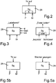
- ein Prinzipschaubild zur Erläuterung eines Initiierungsvorgangs vor dem Koppeln einer Ladestation ist,
- Fig. 3
- ein Prinzipschaubild zur Erläuterung eines Initiierungsvorgangs nach Ankoppeln einer Ladestation, aber vor dem Laden ist,
- Fig. 4
- ein Prinzipschaubild zur Erläuterung eines Verfahrens zum Beenden des Ladevorgangs ist,
- Fig. 5a und 5b
- Prinzipschaubilder zur Erläuterung eines Verfahrens zur Herstellung einer Fahrbereitschaft des Kraftfahrzeugs nach Beendigung eines Ladevorgangs sind,
- Fig. 6
- schematisch ein Schloss für einen Schlüssel eines Kraftfahrzeugs und über dieses Schloss ansteuerbare Einheiten veranschaulicht,
- Fig. 7
- einen Zeitablauf im Zusammenhang mit einem Ladevorgang anhand eines Zeitstrahles veranschaulicht, wobei unterschiedliche Zeiten und Zeitspannen den unterschiedlichen Schaubildern aus den
Fig. 2 bis 6 zugeordnet sind. - Ein im Ganzen mit 100 bezeichnetes Kraftfahrzeug mit einem elektrischen Antrieb 10 soll von einem Fahrer 12 bedienbar sein. Zur Versorgung des elektrischen Antriebs 10 mit elektrischer Energie umfasst das Fahrzeug 100 eine Batterie 14. Diese ist mit einer Buchse 16 mit elektrischen Kontakten gekoppelt, über die die Batterie 14 geladen werden kann. Neben dem elektrischen Antrieb kann ein Verbrennungsmotor (nicht gezeigt) vorgesehen sein, dann ist der elektrische Antrieb Teil eines Hybridantriebs.
- Zum Laden wird das Kraftfahrzeug 100 an eine Ladestation 18 gefahren, von der eine in
Fig. 1 mit 20 bezeichnete und schematisch gezeigte Leitung mit einem Stecker 21 mit der Ladebuchse 16 gekoppelt wird, indem der Stecker 21 eingesteckt wird. Im normalen Zustand während der Fahrt des Kraftfahrzeugs ist die Buchse 16 von einem Tankdeckel 22 verschlossen; inFig. 1 ist dieser im geöffneten Zustand gezeigt. - Steckt der Stecker 21 in der Ladebuchse 16, so lässt sich die Verbindung durch ein schematisch gezeigtes Verriegelungselement 24 verriegeln, wobei ein Aktuator 26 das Verriegelungselement 24 betätigt. Der Aktuator 26 wird von einem Steuergerät 28 angesteuert. Dasselbe Steuergerät steuert auch einen Aktuator 30 für eine Verriegelung 32, die den Tankdeckel 22 während des Betriebs verriegelt. Das Steuergerät 28 ist auch mit einer Einheit 34 gekoppelt, welche selbsttätig einen von dem Kraftfahrzeugführer am Mann getragenen Transponderschlüssel 36 erkennt, für die so genannte Funktion des "Keyless Entry", also das automatische Entriegeln der Kraftfahrzeugtüren, wenn sich der Kraftfahrzeugführer 12 mit dem Transponderschlüssel 36 in die Nähe des Kraftfahrzeugs begibt.
- Das Kraftfahrzeug 100 weist eine Schaltung 36 auf, mit der Betriebszustände wählbar sind, insbesondere wahlweise das Kraftfahrzeug in den Zustand zum Fahren verbracht wird ("D"), oder in einen Parkzustand verbracht wird ("P"), bei dem z. B. ein Getriebe verriegelt ist. Die Schaltung 36 umfasst einen Wahlhebel 37. Dessen Stellung wird durch einen Sensor 38 erfasst.
- Mit Hilfe eines herkömmlichen Schlüssels 39 lässt sich über ein Schloss 40 das Kraftfahrzeug ansteuern, insbesondere darin befindliche elektrische Geräte sowie der elektrische Antrieb 10 selbst. Als Beispiel für elektrische Geräte seien ein Navigationssystem 42 sowie ein Radio mit Lautsprecher 44 genannt. Auch eine Klimaanlage 46 lässt sich über das Schloss 40 in Betrieb setzen, genauso eine Innenbeleuchtung/Lampe 47. Schließlich verfügt das Kraftfahrzeug 100 noch über eine Feststellbremse 48, welche über einen Betätigungshebel 50 angelegt werden kann, indem dieser Hebel gezogen wird. Ein Sensor 49 an der Feststellbremse 48 und ein Sensor 51 an dem Betätigungshebel 50 erfassen den Zustand "Bremse angelegt". Die Feststellbremse 48 ist durch einen Riegel 59 im angezogenen Zustand blockierbar, der Wahlhebel 37 durch einen Riegel 61 in der Parkstellung blockierbar.
- Ein Funkempfänger 53 kann externe Signale empfangen.
- Es wird nachfolgend beschrieben, wie der Vorgang eines Ladens des Kraftfahrzeugs 100 durch die Ladestation 18 durchlaufen wird.
- Zunächst einmal muss der Kraftfahrzeugführer 12 das Kraftfahrzeug 100 zur Ladestation 18 bewegen. Damit die Ladestation 18 über die Leitung 20 mit der Buchse 16 gekoppelt werden kann, muss der Tankdeckel 22 geöffnet werden. Im Grundzustand, während des normalen Fahrbetriebs des Kraftfahrzeugs 100, ist der Tankdeckel 22 durch das Verriegelungselement 32 geschlossen .
- Vorliegend soll der Tankdeckel 22 erst dann verriegelt werden, wenn der Wahlhebel 37 der Automatikschaltung 36 in der Parkstellung "P" steht. Dies wird durch den Sensor 38 erfasst. Gleichzeitig soll die Feststellbremse 48 anliegen, also der Betätigungshebel 50 gezogen sein. Dies wird durch die Sensoren 49 und 51 erfasst. Ist sowohl die Stellung "P" erreicht, als auch die Bremse gezogen ("BR"), so wird gemäß
Fig. 2 durch das Steuergerät 28 der Aktuator 30 dazu gebracht, den Tankdeckel 22 zu entriegeln ("Td auf"). - Wenn die Parkstellung des Automatikgetriebes 36 eingestellt ist und gleichzeitig die Feststellbremse 48 anliegt, ist ein Wegrollen des Kraftfahrzeugs wirksam unterbunden. Dann ist ein sicherer Zustand hergestellt, in dem die Ladestation 18 mit der Ladebuchse 16 über einen Stecker gekoppelt werden kann. Ist diese Sicherheit nicht gegeben, ist eine Verbindung nicht möglich, weil der Tankdeckel 22 geschlossen bleibt.
- Der anhand von
Fig. 2 beschriebene Vorgang wird insbesondere während einer Initiierungsphase zu einem inFig. 7 beispielhaft gezeigten Zeitpunkt t0 durchgeführt. - Nach Beendigung des Vorgangs gemäß
Fig. 2 kann der Stecker 21 in die Buchse 16 eingesteckt werden. - Nun soll gewährleistet sein, dass dieser Stecker 21 während des Ladens nicht unvermittelt herausgezogen wird, denn dann könnte die Batterie 14 oder auch die Ladestation 18 Schaden nehmen, und auch eine den Stecker 21 herausziehende Person wäre gefährdet. Aus diesem Grund wird der Stecker 21 während des Ladens durch die Verriegelungseinheit 24 verriegelt.
- Das Verriegeln erfolgt vor dem Einsetzen des eigentlichen Ladens unter vorbestimmten Bedingungen, die nachfolgend anhand von
Fig. 3 erläutert werden:
Nach wie vor soll der Wahlhebel 37 in der Parkstellung ("P") sein, und die Feststellbremse 48 soll wirksam sein ("BR"). Dies wird durch die Sensoren 38 und 49, 51 erfasst. Gleichzeitig soll die Batterie 14 in einen bestimmten Zustand versetzt sein ("BATT"), und auch weitere elektrische Einrichtungen ("e-") sollen in einem solchen Zustand sein, dass sie durch den Ladevorgang nicht in ihrem Betrieb beeinträchtigt oder beschädigt werden. Schließlich kann zusätzlich vorgesehen sein, dass ein externes Signal ("ext") beim Funkempfänger 53 eingeht, insbesondere von der Ladestation 18, demgemäß eine Freigabe für das Laden erfolgt ist. Ein solches Freigabesignal kann beispielsweise dann abgegeben werden, wenn der Fahrzeugführer 12 vorab eine bestimmte Menge an Energie (kWh) bezahlt hat. Erst, wenn diese Bedingungen sämtlich erfüllt sind, stellt das Steuergerät 28 ("SG") den Zustand der Ladebereitschaft fest. Erst dann wird ein Stromfluss von der Ladestation 18 zur Batterie 14 über die Buchse 16 ermöglicht. - Der anhand der
Fig. 3 erläuterte Vorgang erfolgt im Übergang von der Phase einer Initiierung zur Phase des Ladens zu einem Zeitpunkt t1, siehe die verschiedene Möglichkeiten für den Zeitpunkt t1 angehende Zeitspanne inFig. 7 . - Es kann nun sein, dass sich der Fahrzeugführer 12 während des Ladens in das Kraftfahrzeug 100 begeben möchte und dort Funktionen des Kraftfahrzeugs nutzen möchte.
- Es ist bekannt, dass Schlösser nach Art des in
Fig. 6 näher gezeigten Schlosses 40 ermöglichen, dass ein Schlüssel 39 in drei unterschiedliche Stellungen A, B und C verbringbar sind. Die Stellung A entspricht einem Stillstand des Kraftfahrzeugs und einem Ausgeschaltetsein sämtlicher Geräte, also einem Ruhe-Betriebszustand. In der Stellung B fährt das Kraftfahrzeug, der Antrieb 10 ist also eingeschaltet, das Kraftfahrzeug befindet sich im Fahr-Betriebszustand, wenn zuvor der Schlüssel in Stellung C gebracht wurde. Die Stellung B kann eine Zwischenstellung sein. Bei Kraftfahrzeugen mit Verbrennungskraftmaschine entspricht dieser Zwischenstellung B die so genannte "Klemme 15" ein. In der Zwischenstellung sind das Navigationsgerät 42 und das Radio 44 sowie die Klimaanlage 46 sowie gegebenenfalls ein Bildschirm 52, insbesondere für ein Fernseher, mit Strom versorgt und können in Betrieb gesetzt sein. Ferner kann die Lampe 47 der Innenbeleuchtung zum Leuchten gebracht werden. - Es versteht sich von selbst, dass kein Übergang während des Ladevorgangs nach Zustand C möglich ist, indem eine Einheit 54 für eine Blockade des Ladens sorgt. Umgekehrt sorgt bei der Stellung A und B des Schlüssels eine Einheit 56 dafür, dass die Batterie 14 geladen wird.
- Vorliegend soll auch bei Stellung B eine Verbindung 58 zur Einheit 56 hergestellt sein, damit auch bei dieser Zwischenstellung B ein Laden durch die Einheit 56 ermöglicht ist.
- Somit können während des Ladens das Navigationsgerät 42, das Radio 44, die Klimaanlage 46, die Lampe 47 und der Bildschirm 52 in Betrieb gehalten werden. Der Fahrzeugführer 12, der sich im Kraftfahrzeug 100 befindet, erfährt eine angenehme Klimatisierung des Kraftfahrzeugs, kann das vollständige Infotainmentsystem des Kraftfahrzeugs 100 nutzen, und dieses ist genügend gut beleuchtet.
- Der anhand von
Fig. 6 erläuterte Zustand kann zu beliebigen Zeitpunkten t2 während des Ladens eingestellt sein, vgl.Fig. 7 . - Das Laden einer elektrischen Batterie 14 dauert verhältnismäßig lange, insbesondere mehrere Stunden. Es kann nun sein, dass ein Kraftfahrzeugführer 12 das Laden vorzeitig beenden möchte. Dies wird vorliegend durch eine in dem Kraftfahrzeug 100 bereitgestellte Funktionalität erleichtert: Die Einheit 34 erfasst, wenn der Benutzer 12 mit dem für die Funktionalität des "Keyless-Go" bereitgestellten Transponderschlüssel 36 in die Nähe des Kraftfahrzeugs 100 kommt. Dies wird dem Steuergerät 28 über Signale mitgeteilt. Das Steuergerät 28 beendet dann automatisch den Ladevorgang ("Ende Laden") und z. B. wird auch das Verriegelungselement 24 durch den Aktuator 26 entriegelt.
- Gleichermaßen kann der Ladevorgang beendet werden, wenn der Kraftfahrzeugführer 12 mit Hilfe eines herkömmlichen Schlüssels das Kraftfahrzeug entweder öffnet oder diesen Schlüssel 39 in das Schloss 40 steckt.
- Naturgemäß möchte nicht jeder Kraftfahrzeugführer 12, der in die Nähe seines Kraftfahrzeugs 100 beim Ladevorgang kommt, den Ladevorgang beenden. Aus diesem Grund wird erfasst, ob der Fahrzeugführer 12 nachfolgend den Stecker aus der Buchse 16 zieht, oder ob er den Tankdeckel 22 verschließt, ob nach wie vor Strom zur Batterie 14 fließt, oder ob sonst wie die Fortsetzung des Ladevorgangs unmöglich gemacht wird. Erfasst das Steuergerät 28 derartiges nicht, so wird das Laden nach einer vorbestimmten Zeitdauer wieder aufgenommen und der Ladevorgang fortgesetzt.
- Der anhand von
Fig. 4 erläuterte Vorgang erfolgt zu einem Zeitpunkt t3 während einer inFig. 7 dargestellten Zeitdauer im Übergang vom Laden zum Beenden des Ladens. - Es soll nun verhindert werden, dass ein Kraftfahrzeugführer das Kraftfahrzeug in Betrieb nimmt, während die Ladestation 18 weiter mit dem Kraftfahrzeug 100 gekoppelt ist. Aus diesem Grund ist vorgesehen, dass ein Verbringen des Wahlhebels 37 aus der Parkstellung "P" der Automatikschaltung 36 heraus zunächst nicht möglich, z. B. weil der Wahlhebel 37 in der Parkstellung "P" mit dem Riegel 61 verriegelt ist. Genauso wird durch den Riegel 59 verhindert, dass die Feststellbremse 48 gelöst wird.
- Bei einer Alternative wird diese Verriegelung aufgehoben, wenn der Stecker aus der Buchse 16 gezogen ist, was durch einen geeigneten Sensor 58 erfasst werden kann. Wie in
Fig. 5a gezeigt, wird erst nach Ziehen des Steckers der Wahlhebel 37 wieder freigegeben bzw. die Bremse "BR" wieder lösbar gemacht. - Alternativ kann vorgesehen sein, dass zunächst der Tankdeckel 22 geschlossen werden muss, was z. B. durch einen Sensor 68 erfasst werden kann, und das Steuergerät 28 bewirkt erst bei geschlossenem Tankdeckel, dass der Wahlhebel 37 aus der Parkstellung "P" herausbewegt werden kann und die Feststellbremse 48 gelöst werden kann ("BR").
- Der anhand der
Fig. 5a und 5b erläuterte Vorgang erfolgt während einer Phase des Beendens des Ladens, z. B. zum in derFig. 7 beispielhaft gezeigten Zeitpunkt t4. - Anschließend ist das Kraftfahrzeug fahrbereit, und es kann mit geladener Batterie 14 der elektrische Antrieb 10 wieder in Betrieb gesetzt werden.
Claims (8)
- Verfahren zum Laden einer Batterie (14) eines Kraftfahrzeugs (100) mit elektrischem Antrieb (10), wobei zum Laden eine Außenanschlusseinrichtung (20) einer Ladestation (18) mit einer Fahrzeuganschlusseinrichtung (16) des Kraftfahrzeugs (100) gekoppelt wird und an dieser verriegelbar ist, mit den Schritten:- Überprüfen nach zumindest einem vorbestimmten Kriterium, ob eine Bereitschaft zum Laden gegeben ist,- Verriegeln der Außenanschlusseinrichtung (20) an der Fahrzeuganschlusseinrichtung (16) bei Feststellen der Bereitschaft zum Laden,- Beginnen des Ladens nach dem Verriegeln,gekennzeichnet durch die Schritte:- Erkennen eines von einem Kraftfahrzeugführer (12) am Mann getragenen Transponderschlüssels (36),- Automatisches Beenden des Ladevorgangs, wenn der Fahrzeugführer (12) mit dem Transponderschlüssel (36) in die Nähe des Kraftfahrzeugs (100) kommt,- Fortsetzen des Ladevorgangs mittels eines Steuergeräts (28) nach einer vorbestimmten Zeitdauer, sofern ein Erfassen, dass der Kraftfahrzeugführer (12) einen Stecker (21) aus einer Buchse (16) zieht und/oder dass der Kraftfahrzeugführer (12) einen Tankdeckel (22) verschließt und/oder dass sonst wie die Fortsetzung des Ladevorgangs unmöglich gemacht wird, durch das Steuergerät (28) unterbleibt.
- Verfahren nach Anspruch 1, bei dem zumindest ein vorbestimmtes Kriterium auf eine Einrichtung des Kraftfahrzeugs (100) bezogen ist, die von der Fahrzeuganschlusseinrichtung (16) verschieden ist.
- Verfahren nach Anspruch 1 oder 2, bei dem zum Feststellen der Bereitschaft zum Laden eine Bremsvorrichtung (48) des Kraftfahrzeugs (100) wirksam sein muss und/oder ein Betriebszustand-Wahlelement (37) des Kraftfahrzeugs (100) einen vorbestimmten Zustand einnehmen muss.
- Verfahren nach einem der vorhergehenden Ansprüche, bei dem zum Feststellen der Bereitschaft zum Laden ein vorbestimmtes Signal ("ext") von außerhalb des Kraftfahrzeugs an dieses übermittelt worden sein muss oder werden kann.
- Verfahren nach einem der vorhergehenden Ansprüche, bei dem zum Feststellen der Bereitschaft zum Laden die zu ladende Batterie und/oder eine andere elektrische Funktionseinheit des Kraftfahrzeugs einen vorbestimmten Zustand einnehmen muss bzw. müssen und hierzu ein entsprechendes Signal abgegeben worden sein muss.
- Verfahren nach einem der vorhergehenden Ansprüche, bei dem das Steuergerät (28) das Verriegeln bewirkt, welches ausgelegt ist, das Erfülltsein eines vorbestimmten Kriteriums anhand von zumindest einem empfangenen Signal festzustellen.
- Kraftfahrzeug (100) mit zumindest einem elektrischem Antrieb (10) und einer Batterie (14), mit einer Fahrzeuganschlusseinrichtung (16), welche zum Laden der Batterie (14) mit einer Außenanschlusseinrichtung (20) einer Ladestation (18) koppelbar und an dieser verriegelbar ist, mit einem Steuergerät (28), welches dazu ausgelegt ist,- nach zumindest einem vorbestimmten Kriterium zu überprüfen, ob eine Bereitschaft zum Laden gegeben ist, und- die Außenanschlusseinrichtung (20) an der Fahrzeuganschlusseinrichtung (16) bei Feststellen der Bereitschaft zum Laden zu verriegeln, wobei das Laden nach dem Verriegeln beginnt,dadurch gekennzeichnet, dass
das Steuergerät (28) mit einer Einheit (34) gekoppelt ist, welche dazu ausgelegt ist, einen von einem Kraftfahrzeugführer (12) am Mann getragenen Transponderschlüssel (36) zu erkennen, und dass das Steuergerät (28) dazu ausgelegt ist, den Ladevorgang automatisch zu beenden, wenn der Fahrzeugführer (12) mit dem Transponderschlüssel (36) in die Nähe des Kraftfahrzeugs (100) kommt, und den Ladevorgang nach einer vorbestimmten Zeitdauer fortzusetzen, sofern ein Erfassen, dass der Kraftfahrzeugführer (12) einen Stecker (21) aus einer Buchse (16) zieht und/oder dass der Kraftfahrzeugführer (12) einen Tankdeckel (22) verschließt und/oder dass sonst wie die Fortsetzung des Ladevorgangs unmöglich gemacht wird, durch das Steuergerät (28) unterbleibt. - Kraftfahrzeug (100) nach Anspruch 7, bei dem das Steuergerät (28) dazu ausgelegt ist, Signale von Funktionseinheiten (38; 49, 51; 53) des Kraftfahrzeugs (100) zu erhalten und in Abhängigkeit von solchen Signalen nach dem zumindest einen vorbestimmten Kriterium die Ladebereitschaft festzustellen und das Verriegeln zu bewirken
Applications Claiming Priority (2)
| Application Number | Priority Date | Filing Date | Title |
|---|---|---|---|
| DE102010009727A DE102010009727A1 (de) | 2010-03-01 | 2010-03-01 | Verfahren zum Laden einer Batterie eines Kraftfahrzeugs mit elektrischem Antrieb sowie Kraftfahrzeug mit elektrischem Antrieb |
| PCT/EP2011/000499 WO2011107197A2 (de) | 2010-03-01 | 2011-02-03 | Verfahren zum laden einer batterie eines kraftfahrzeugs mit elektrischem antrieb sowie kraftfahrzeug mit elektrischem antrieb |
Publications (2)
| Publication Number | Publication Date |
|---|---|
| EP2542444A2 EP2542444A2 (de) | 2013-01-09 |
| EP2542444B1 true EP2542444B1 (de) | 2019-12-04 |
Family
ID=44501989
Family Applications (1)
| Application Number | Title | Priority Date | Filing Date |
|---|---|---|---|
| EP11704540.1A Active EP2542444B1 (de) | 2010-03-01 | 2011-02-03 | Verfahren zum laden einer batterie eines kraftfahrzeugs mit elektrischem antrieb |
Country Status (3)
| Country | Link |
|---|---|
| EP (1) | EP2542444B1 (de) |
| DE (1) | DE102010009727A1 (de) |
| WO (1) | WO2011107197A2 (de) |
Families Citing this family (4)
| Publication number | Priority date | Publication date | Assignee | Title |
|---|---|---|---|---|
| JP5452653B2 (ja) | 2012-04-05 | 2014-03-26 | 三菱電機株式会社 | 電動車両、および、電動車両の充電制御方法 |
| DE102012007047B3 (de) * | 2012-04-05 | 2013-04-18 | Schaltbau Gmbh | Fahrzeugseitige Dose eines Ladesteckverbinders, insbesondere für Flurförderfahrzeuge |
| SE538801C2 (en) * | 2015-02-18 | 2016-12-06 | Scania Cv Ab | Method and control system for charging a vehicle |
| SE538693C2 (en) | 2015-02-18 | 2016-10-18 | Scania Cv Ab | Method and control system for charging a hybrid vehicle |
Citations (3)
| Publication number | Priority date | Publication date | Assignee | Title |
|---|---|---|---|---|
| US20090085522A1 (en) * | 2007-09-27 | 2009-04-02 | Denso Corporation | Charging system |
| EP2108538A1 (de) * | 2007-01-04 | 2009-10-14 | Toyota Jidosha Kabushiki Kaisha | Fahrzeug, fahrzeugsteuerverfahren und computerlesbares aufzeichnungsmedium mit einem programm zum bewirken, dass der computer das fahrzeugsteuerverfahren ausführt |
| DE102010011162A1 (de) * | 2009-07-15 | 2011-02-03 | Siemens Aktiengesellschaft | Verfahren zur Kommunikation zwischen einem Elektrofahrzeug und einer Ladestelle zum elektrischen Laden zumindest eines Energiespeichers des Elektrofahrzeugs |
Family Cites Families (6)
| Publication number | Priority date | Publication date | Assignee | Title |
|---|---|---|---|---|
| JPH06343202A (ja) * | 1993-06-01 | 1994-12-13 | Nissan Motor Co Ltd | 電気自動車の充電装置 |
| JP2916348B2 (ja) | 1993-07-22 | 1999-07-05 | 住友電装株式会社 | 電気自動車充電用コネクタ |
| JP3629094B2 (ja) * | 1996-06-03 | 2005-03-16 | 本田技研工業株式会社 | 電気自動車 |
| JPH10262303A (ja) * | 1997-03-18 | 1998-09-29 | Honda Motor Co Ltd | バッテリを動力の少なくとも一部とする車両の充電装置 |
| JP4379823B2 (ja) * | 2007-09-25 | 2009-12-09 | 株式会社デンソー | 車両の充電システム |
| JP5339983B2 (ja) * | 2008-05-19 | 2013-11-13 | 富士重工業株式会社 | 電気自動車の制御装置 |
-
2010
- 2010-03-01 DE DE102010009727A patent/DE102010009727A1/de not_active Withdrawn
-
2011
- 2011-02-03 WO PCT/EP2011/000499 patent/WO2011107197A2/de not_active Ceased
- 2011-02-03 EP EP11704540.1A patent/EP2542444B1/de active Active
Patent Citations (3)
| Publication number | Priority date | Publication date | Assignee | Title |
|---|---|---|---|---|
| EP2108538A1 (de) * | 2007-01-04 | 2009-10-14 | Toyota Jidosha Kabushiki Kaisha | Fahrzeug, fahrzeugsteuerverfahren und computerlesbares aufzeichnungsmedium mit einem programm zum bewirken, dass der computer das fahrzeugsteuerverfahren ausführt |
| US20090085522A1 (en) * | 2007-09-27 | 2009-04-02 | Denso Corporation | Charging system |
| DE102010011162A1 (de) * | 2009-07-15 | 2011-02-03 | Siemens Aktiengesellschaft | Verfahren zur Kommunikation zwischen einem Elektrofahrzeug und einer Ladestelle zum elektrischen Laden zumindest eines Energiespeichers des Elektrofahrzeugs |
Also Published As
| Publication number | Publication date |
|---|---|
| DE102010009727A1 (de) | 2011-09-01 |
| WO2011107197A2 (de) | 2011-09-09 |
| EP2542444A2 (de) | 2013-01-09 |
| WO2011107197A3 (de) | 2012-04-26 |
Similar Documents
| Publication | Publication Date | Title |
|---|---|---|
| EP2542443B1 (de) | Verfahren zum laden einer batterie eines kraftfahrzeugs | |
| EP3017186B1 (de) | Kraftwagen mit einer fernstarteinheit | |
| DE102014209210A1 (de) | Steuern einer Verriegelungsvorrichtung eines elektrischen Ladeanschlusses | |
| EP4367349B1 (de) | Türschloss, insbesondere kraftfahrzeug-türschloss | |
| DE102004024353B4 (de) | Schlüsselloses Smart-Start-System | |
| EP3010749B1 (de) | Anschlussvorrichtung für eine elektrische anlage eines fahrzeugs sowie verfahren zu deren betrieb, mit funkschlüssel | |
| EP2403734B1 (de) | Verfahren und vorrichtung zur steuerung einer fahrzeugbewegungsmöglichkeit und/oder einer verschlussvorrichtung | |
| DE102009021720A1 (de) | Steuervorrichtung für Elektrofahrzeuge | |
| DE102008048310A1 (de) | Ladesystem für Fahrzeuge | |
| WO2009016144A1 (de) | Benutzeridentifizierungsvorrichtung | |
| DE102014224095B4 (de) | Motor-zünd-/getriebeschaltsperre | |
| DE102018207768A1 (de) | Verfahren zur Bereitstellung von elektrischer Energie für ein Kraftfahrzeug sowie ein zugehöriges Versorgerfahrzeug | |
| DE102018211130A1 (de) | System und Verfahren zum Entriegeln eines in eine Ladedose eines Kraftfahrzeugs eingesteckten Ladesteckers | |
| WO2011107197A2 (de) | Verfahren zum laden einer batterie eines kraftfahrzeugs mit elektrischem antrieb sowie kraftfahrzeug mit elektrischem antrieb | |
| DE102015012864A1 (de) | Ladeeinrichtung zum Laden eines elektrischen Energiespeichers eines Kraftwagens | |
| DE102014001646A1 (de) | Ladevorrichtung für ein elektrisch angetriebenes Fahrzeug | |
| DE102016010244A1 (de) | Schließelement, insbesondere für ein Kraftfahrzeug | |
| DE102010052375B4 (de) | Kraftfahrzeug mit einem über eine Erfassungseinrichtung betätigbaren Sperrmittel zur Verhinderung eines unautorisierten Ladens des Kraftfahrzeugs | |
| DE102014015576A1 (de) | Ladeeinrichtung zum Aufladen einer Batterie eines Kraftwagens | |
| DE4429418C2 (de) | Sicherungseinrichtung mit Zugangsschutz und Wegfahrsperre für Fahrzeuge | |
| DE102017211418B3 (de) | Kraftfahrzeug | |
| DE102008057602A1 (de) | Verfahren und Vorrichtung zum Betreiben eines Kraftfahrzeugs | |
| DE102008012413A1 (de) | Deaktivierung der Start-Stopp-Funktionalität eines Fahrzeuges mit Keyless-Funktionen | |
| DE102010009726A1 (de) | Kraftfahrzeug mit elektrischem Antrieb und Batterie sowie Verfahren zum Laden einer Batterie eines Kraftfahrzeugs mit elektrischem Antrieb | |
| DE19848375C1 (de) | Vorrichtung und Verfahren zum Starten eines Kraftfahrzeugs |
Legal Events
| Date | Code | Title | Description |
|---|---|---|---|
| PUAI | Public reference made under article 153(3) epc to a published international application that has entered the european phase |
Free format text: ORIGINAL CODE: 0009012 |
|
| 17P | Request for examination filed |
Effective date: 20121026 |
|
| AK | Designated contracting states |
Kind code of ref document: A2 Designated state(s): AL AT BE BG CH CY CZ DE DK EE ES FI FR GB GR HR HU IE IS IT LI LT LU LV MC MK MT NL NO PL PT RO RS SE SI SK SM TR |
|
| RIN1 | Information on inventor provided before grant (corrected) |
Inventor name: THEN, FLORIAN Inventor name: UNGERMANN, JOCHEN Inventor name: ANDREE, DANIEL Inventor name: KRUSE, ALEXANDER |
|
| DAX | Request for extension of the european patent (deleted) | ||
| 17Q | First examination report despatched |
Effective date: 20141212 |
|
| STAA | Information on the status of an ep patent application or granted ep patent |
Free format text: STATUS: EXAMINATION IS IN PROGRESS |
|
| REG | Reference to a national code |
Ref country code: DE Ref legal event code: R079 Ref document number: 502011016296 Country of ref document: DE Free format text: PREVIOUS MAIN CLASS: B60L0011180000 Ipc: B60L0003000000 |
|
| GRAP | Despatch of communication of intention to grant a patent |
Free format text: ORIGINAL CODE: EPIDOSNIGR1 |
|
| STAA | Information on the status of an ep patent application or granted ep patent |
Free format text: STATUS: GRANT OF PATENT IS INTENDED |
|
| RIC1 | Information provided on ipc code assigned before grant |
Ipc: B60L 53/60 20190101ALI20190719BHEP Ipc: B60L 50/60 20190101ALI20190719BHEP Ipc: B60L 3/00 20190101AFI20190719BHEP Ipc: B60L 53/16 20190101ALI20190719BHEP Ipc: B60L 50/16 20190101ALI20190719BHEP |
|
| INTG | Intention to grant announced |
Effective date: 20190807 |
|
| GRAS | Grant fee paid |
Free format text: ORIGINAL CODE: EPIDOSNIGR3 |
|
| GRAA | (expected) grant |
Free format text: ORIGINAL CODE: 0009210 |
|
| STAA | Information on the status of an ep patent application or granted ep patent |
Free format text: STATUS: THE PATENT HAS BEEN GRANTED |
|
| AK | Designated contracting states |
Kind code of ref document: B1 Designated state(s): AL AT BE BG CH CY CZ DE DK EE ES FI FR GB GR HR HU IE IS IT LI LT LU LV MC MK MT NL NO PL PT RO RS SE SI SK SM TR |
|
| REG | Reference to a national code |
Ref country code: GB Ref legal event code: FG4D Free format text: NOT ENGLISH |
|
| REG | Reference to a national code |
Ref country code: CH Ref legal event code: EP |
|
| REG | Reference to a national code |
Ref country code: AT Ref legal event code: REF Ref document number: 1208962 Country of ref document: AT Kind code of ref document: T Effective date: 20191215 |
|
| REG | Reference to a national code |
Ref country code: DE Ref legal event code: R096 Ref document number: 502011016296 Country of ref document: DE |
|
| REG | Reference to a national code |
Ref country code: IE Ref legal event code: FG4D Free format text: LANGUAGE OF EP DOCUMENT: GERMAN |
|
| REG | Reference to a national code |
Ref country code: NL Ref legal event code: MP Effective date: 20191204 |
|
| REG | Reference to a national code |
Ref country code: LT Ref legal event code: MG4D |
|
| PG25 | Lapsed in a contracting state [announced via postgrant information from national office to epo] |
Ref country code: FI Free format text: LAPSE BECAUSE OF FAILURE TO SUBMIT A TRANSLATION OF THE DESCRIPTION OR TO PAY THE FEE WITHIN THE PRESCRIBED TIME-LIMIT Effective date: 20191204 Ref country code: BG Free format text: LAPSE BECAUSE OF FAILURE TO SUBMIT A TRANSLATION OF THE DESCRIPTION OR TO PAY THE FEE WITHIN THE PRESCRIBED TIME-LIMIT Effective date: 20200304 Ref country code: SE Free format text: LAPSE BECAUSE OF FAILURE TO SUBMIT A TRANSLATION OF THE DESCRIPTION OR TO PAY THE FEE WITHIN THE PRESCRIBED TIME-LIMIT Effective date: 20191204 Ref country code: NO Free format text: LAPSE BECAUSE OF FAILURE TO SUBMIT A TRANSLATION OF THE DESCRIPTION OR TO PAY THE FEE WITHIN THE PRESCRIBED TIME-LIMIT Effective date: 20200304 Ref country code: LV Free format text: LAPSE BECAUSE OF FAILURE TO SUBMIT A TRANSLATION OF THE DESCRIPTION OR TO PAY THE FEE WITHIN THE PRESCRIBED TIME-LIMIT Effective date: 20191204 Ref country code: GR Free format text: LAPSE BECAUSE OF FAILURE TO SUBMIT A TRANSLATION OF THE DESCRIPTION OR TO PAY THE FEE WITHIN THE PRESCRIBED TIME-LIMIT Effective date: 20200305 Ref country code: LT Free format text: LAPSE BECAUSE OF FAILURE TO SUBMIT A TRANSLATION OF THE DESCRIPTION OR TO PAY THE FEE WITHIN THE PRESCRIBED TIME-LIMIT Effective date: 20191204 Ref country code: ES Free format text: LAPSE BECAUSE OF FAILURE TO SUBMIT A TRANSLATION OF THE DESCRIPTION OR TO PAY THE FEE WITHIN THE PRESCRIBED TIME-LIMIT Effective date: 20191204 |
|
| PG25 | Lapsed in a contracting state [announced via postgrant information from national office to epo] |
Ref country code: HR Free format text: LAPSE BECAUSE OF FAILURE TO SUBMIT A TRANSLATION OF THE DESCRIPTION OR TO PAY THE FEE WITHIN THE PRESCRIBED TIME-LIMIT Effective date: 20191204 Ref country code: RS Free format text: LAPSE BECAUSE OF FAILURE TO SUBMIT A TRANSLATION OF THE DESCRIPTION OR TO PAY THE FEE WITHIN THE PRESCRIBED TIME-LIMIT Effective date: 20191204 |
|
| PG25 | Lapsed in a contracting state [announced via postgrant information from national office to epo] |
Ref country code: AL Free format text: LAPSE BECAUSE OF FAILURE TO SUBMIT A TRANSLATION OF THE DESCRIPTION OR TO PAY THE FEE WITHIN THE PRESCRIBED TIME-LIMIT Effective date: 20191204 |
|
| PG25 | Lapsed in a contracting state [announced via postgrant information from national office to epo] |
Ref country code: EE Free format text: LAPSE BECAUSE OF FAILURE TO SUBMIT A TRANSLATION OF THE DESCRIPTION OR TO PAY THE FEE WITHIN THE PRESCRIBED TIME-LIMIT Effective date: 20191204 Ref country code: CZ Free format text: LAPSE BECAUSE OF FAILURE TO SUBMIT A TRANSLATION OF THE DESCRIPTION OR TO PAY THE FEE WITHIN THE PRESCRIBED TIME-LIMIT Effective date: 20191204 Ref country code: NL Free format text: LAPSE BECAUSE OF FAILURE TO SUBMIT A TRANSLATION OF THE DESCRIPTION OR TO PAY THE FEE WITHIN THE PRESCRIBED TIME-LIMIT Effective date: 20191204 Ref country code: RO Free format text: LAPSE BECAUSE OF FAILURE TO SUBMIT A TRANSLATION OF THE DESCRIPTION OR TO PAY THE FEE WITHIN THE PRESCRIBED TIME-LIMIT Effective date: 20191204 Ref country code: PT Free format text: LAPSE BECAUSE OF FAILURE TO SUBMIT A TRANSLATION OF THE DESCRIPTION OR TO PAY THE FEE WITHIN THE PRESCRIBED TIME-LIMIT Effective date: 20200429 |
|
| PG25 | Lapsed in a contracting state [announced via postgrant information from national office to epo] |
Ref country code: SM Free format text: LAPSE BECAUSE OF FAILURE TO SUBMIT A TRANSLATION OF THE DESCRIPTION OR TO PAY THE FEE WITHIN THE PRESCRIBED TIME-LIMIT Effective date: 20191204 Ref country code: IS Free format text: LAPSE BECAUSE OF FAILURE TO SUBMIT A TRANSLATION OF THE DESCRIPTION OR TO PAY THE FEE WITHIN THE PRESCRIBED TIME-LIMIT Effective date: 20200404 Ref country code: SK Free format text: LAPSE BECAUSE OF FAILURE TO SUBMIT A TRANSLATION OF THE DESCRIPTION OR TO PAY THE FEE WITHIN THE PRESCRIBED TIME-LIMIT Effective date: 20191204 |
|
| REG | Reference to a national code |
Ref country code: DE Ref legal event code: R097 Ref document number: 502011016296 Country of ref document: DE |
|
| REG | Reference to a national code |
Ref country code: CH Ref legal event code: PL |
|
| PLBE | No opposition filed within time limit |
Free format text: ORIGINAL CODE: 0009261 |
|
| STAA | Information on the status of an ep patent application or granted ep patent |
Free format text: STATUS: NO OPPOSITION FILED WITHIN TIME LIMIT |
|
| REG | Reference to a national code |
Ref country code: BE Ref legal event code: MM Effective date: 20200229 |
|
| PG25 | Lapsed in a contracting state [announced via postgrant information from national office to epo] |
Ref country code: DK Free format text: LAPSE BECAUSE OF FAILURE TO SUBMIT A TRANSLATION OF THE DESCRIPTION OR TO PAY THE FEE WITHIN THE PRESCRIBED TIME-LIMIT Effective date: 20191204 Ref country code: LU Free format text: LAPSE BECAUSE OF NON-PAYMENT OF DUE FEES Effective date: 20200203 Ref country code: MC Free format text: LAPSE BECAUSE OF FAILURE TO SUBMIT A TRANSLATION OF THE DESCRIPTION OR TO PAY THE FEE WITHIN THE PRESCRIBED TIME-LIMIT Effective date: 20191204 |
|
| 26N | No opposition filed |
Effective date: 20200907 |
|
| PG25 | Lapsed in a contracting state [announced via postgrant information from national office to epo] |
Ref country code: CH Free format text: LAPSE BECAUSE OF NON-PAYMENT OF DUE FEES Effective date: 20200229 Ref country code: SI Free format text: LAPSE BECAUSE OF FAILURE TO SUBMIT A TRANSLATION OF THE DESCRIPTION OR TO PAY THE FEE WITHIN THE PRESCRIBED TIME-LIMIT Effective date: 20191204 Ref country code: LI Free format text: LAPSE BECAUSE OF NON-PAYMENT OF DUE FEES Effective date: 20200229 Ref country code: PL Free format text: LAPSE BECAUSE OF FAILURE TO SUBMIT A TRANSLATION OF THE DESCRIPTION OR TO PAY THE FEE WITHIN THE PRESCRIBED TIME-LIMIT Effective date: 20191204 |
|
| PG25 | Lapsed in a contracting state [announced via postgrant information from national office to epo] |
Ref country code: IT Free format text: LAPSE BECAUSE OF FAILURE TO SUBMIT A TRANSLATION OF THE DESCRIPTION OR TO PAY THE FEE WITHIN THE PRESCRIBED TIME-LIMIT Effective date: 20191204 Ref country code: IE Free format text: LAPSE BECAUSE OF NON-PAYMENT OF DUE FEES Effective date: 20200203 |
|
| PG25 | Lapsed in a contracting state [announced via postgrant information from national office to epo] |
Ref country code: BE Free format text: LAPSE BECAUSE OF NON-PAYMENT OF DUE FEES Effective date: 20200229 |
|
| REG | Reference to a national code |
Ref country code: AT Ref legal event code: MM01 Ref document number: 1208962 Country of ref document: AT Kind code of ref document: T Effective date: 20200203 |
|
| PG25 | Lapsed in a contracting state [announced via postgrant information from national office to epo] |
Ref country code: AT Free format text: LAPSE BECAUSE OF NON-PAYMENT OF DUE FEES Effective date: 20200203 |
|
| PGFP | Annual fee paid to national office [announced via postgrant information from national office to epo] |
Ref country code: GB Payment date: 20220221 Year of fee payment: 12 Ref country code: DE Payment date: 20220228 Year of fee payment: 12 |
|
| PG25 | Lapsed in a contracting state [announced via postgrant information from national office to epo] |
Ref country code: TR Free format text: LAPSE BECAUSE OF FAILURE TO SUBMIT A TRANSLATION OF THE DESCRIPTION OR TO PAY THE FEE WITHIN THE PRESCRIBED TIME-LIMIT Effective date: 20191204 Ref country code: MT Free format text: LAPSE BECAUSE OF FAILURE TO SUBMIT A TRANSLATION OF THE DESCRIPTION OR TO PAY THE FEE WITHIN THE PRESCRIBED TIME-LIMIT Effective date: 20191204 Ref country code: CY Free format text: LAPSE BECAUSE OF FAILURE TO SUBMIT A TRANSLATION OF THE DESCRIPTION OR TO PAY THE FEE WITHIN THE PRESCRIBED TIME-LIMIT Effective date: 20191204 |
|
| PGFP | Annual fee paid to national office [announced via postgrant information from national office to epo] |
Ref country code: FR Payment date: 20220219 Year of fee payment: 12 |
|
| PG25 | Lapsed in a contracting state [announced via postgrant information from national office to epo] |
Ref country code: MK Free format text: LAPSE BECAUSE OF FAILURE TO SUBMIT A TRANSLATION OF THE DESCRIPTION OR TO PAY THE FEE WITHIN THE PRESCRIBED TIME-LIMIT Effective date: 20191204 |
|
| P01 | Opt-out of the competence of the unified patent court (upc) registered |
Effective date: 20230530 |
|
| REG | Reference to a national code |
Ref country code: DE Ref legal event code: R119 Ref document number: 502011016296 Country of ref document: DE |
|
| GBPC | Gb: european patent ceased through non-payment of renewal fee |
Effective date: 20230203 |
|
| PG25 | Lapsed in a contracting state [announced via postgrant information from national office to epo] |
Ref country code: GB Free format text: LAPSE BECAUSE OF NON-PAYMENT OF DUE FEES Effective date: 20230203 |
|
| PG25 | Lapsed in a contracting state [announced via postgrant information from national office to epo] |
Ref country code: GB Free format text: LAPSE BECAUSE OF NON-PAYMENT OF DUE FEES Effective date: 20230203 Ref country code: FR Free format text: LAPSE BECAUSE OF NON-PAYMENT OF DUE FEES Effective date: 20230228 Ref country code: DE Free format text: LAPSE BECAUSE OF NON-PAYMENT OF DUE FEES Effective date: 20230901 |