EP2541713B1 - Structure de fixation pour cuve et couvercle, ainsi que procédé de fixation pour cuve et couvercle - Google Patents
Structure de fixation pour cuve et couvercle, ainsi que procédé de fixation pour cuve et couvercle Download PDFInfo
- Publication number
- EP2541713B1 EP2541713B1 EP20100846527 EP10846527A EP2541713B1 EP 2541713 B1 EP2541713 B1 EP 2541713B1 EP 20100846527 EP20100846527 EP 20100846527 EP 10846527 A EP10846527 A EP 10846527A EP 2541713 B1 EP2541713 B1 EP 2541713B1
- Authority
- EP
- European Patent Office
- Prior art keywords
- trough
- lid
- projection
- fixing bracket
- bolt
- Prior art date
- Legal status (The legal status is an assumption and is not a legal conclusion. Google has not performed a legal analysis and makes no representation as to the accuracy of the status listed.)
- Active
Links
- 238000000034 method Methods 0.000 title claims description 19
- 230000035515 penetration Effects 0.000 claims description 14
- 239000000463 material Substances 0.000 description 7
- 239000011347 resin Substances 0.000 description 6
- 229920005989 resin Polymers 0.000 description 6
- 230000005489 elastic deformation Effects 0.000 description 5
- 230000000694 effects Effects 0.000 description 4
- 230000003014 reinforcing effect Effects 0.000 description 3
- 238000003466 welding Methods 0.000 description 3
- PXHVJJICTQNCMI-UHFFFAOYSA-N Nickel Chemical compound [Ni] PXHVJJICTQNCMI-UHFFFAOYSA-N 0.000 description 2
- 238000003780 insertion Methods 0.000 description 2
- 230000037431 insertion Effects 0.000 description 2
- 238000009434 installation Methods 0.000 description 2
- 238000004519 manufacturing process Methods 0.000 description 2
- 239000002184 metal Substances 0.000 description 2
- 229910052751 metal Inorganic materials 0.000 description 2
- 229910001369 Brass Inorganic materials 0.000 description 1
- 230000015572 biosynthetic process Effects 0.000 description 1
- 239000010951 brass Substances 0.000 description 1
- 238000010276 construction Methods 0.000 description 1
- 238000005260 corrosion Methods 0.000 description 1
- 230000007797 corrosion Effects 0.000 description 1
- 230000001419 dependent effect Effects 0.000 description 1
- 239000013013 elastic material Substances 0.000 description 1
- 239000004519 grease Substances 0.000 description 1
- 239000000203 mixture Substances 0.000 description 1
- 238000012986 modification Methods 0.000 description 1
- 230000004048 modification Effects 0.000 description 1
- 238000000465 moulding Methods 0.000 description 1
- 229910052759 nickel Inorganic materials 0.000 description 1
- 230000000149 penetrating effect Effects 0.000 description 1
- 230000002093 peripheral effect Effects 0.000 description 1
- 230000000979 retarding effect Effects 0.000 description 1
- 239000004576 sand Substances 0.000 description 1
- 229910001220 stainless steel Inorganic materials 0.000 description 1
- 239000010935 stainless steel Substances 0.000 description 1
- 239000002699 waste material Substances 0.000 description 1
Images


Classifications
-
- H—ELECTRICITY
- H02—GENERATION; CONVERSION OR DISTRIBUTION OF ELECTRIC POWER
- H02G—INSTALLATION OF ELECTRIC CABLES OR LINES, OR OF COMBINED OPTICAL AND ELECTRIC CABLES OR LINES
- H02G9/00—Installations of electric cables or lines in or on the ground or water
- H02G9/04—Installations of electric cables or lines in or on the ground or water in surface ducts; Ducts or covers therefor
-
- H—ELECTRICITY
- H02—GENERATION; CONVERSION OR DISTRIBUTION OF ELECTRIC POWER
- H02G—INSTALLATION OF ELECTRIC CABLES OR LINES, OR OF COMBINED OPTICAL AND ELECTRIC CABLES OR LINES
- H02G3/00—Installations of electric cables or lines or protective tubing therefor in or on buildings, equivalent structures or vehicles
- H02G3/02—Details
- H02G3/04—Protective tubing or conduits, e.g. cable ladders or cable troughs
- H02G3/0406—Details thereof
- H02G3/0418—Covers or lids; Their fastenings
-
- H—ELECTRICITY
- H02—GENERATION; CONVERSION OR DISTRIBUTION OF ELECTRIC POWER
- H02G—INSTALLATION OF ELECTRIC CABLES OR LINES, OR OF COMBINED OPTICAL AND ELECTRIC CABLES OR LINES
- H02G3/00—Installations of electric cables or lines or protective tubing therefor in or on buildings, equivalent structures or vehicles
- H02G3/02—Details
- H02G3/06—Joints for connecting lengths of protective tubing or channels, to each other or to casings, e.g. to distribution boxes; Ensuring electrical continuity in the joint
- H02G3/0608—Joints for connecting non cylindrical conduits, e.g. channels
-
- H—ELECTRICITY
- H02—GENERATION; CONVERSION OR DISTRIBUTION OF ELECTRIC POWER
- H02G—INSTALLATION OF ELECTRIC CABLES OR LINES, OR OF COMBINED OPTICAL AND ELECTRIC CABLES OR LINES
- H02G9/00—Installations of electric cables or lines in or on the ground or water
- H02G9/06—Installations of electric cables or lines in or on the ground or water in underground tubes or conduits; Tubes or conduits therefor
Definitions
- the present invention relates to the fixing structure etc. which fix a trough housing cables inside and placed along a railroad and a road side or the like, and a lid provided in the trough upper part.
- a plastic trough stores various cables inside and constructed over a long distance.
- a lid is provided in the upper part of a trough and the lid is fixed on the trough.
- a trough fixing clip having a hook.
- the clip is provided on both sides of the trough.
- the hook is rotated around a joint part of the clip and the hook.
- the clip engages the lid from both sides of the trough and fixes the lid.
- a lid fixing member for troughs having a top plate part and a side plate part.
- the lid fixing member can fix a lid to a trough by locking the side plate part to a side wall part of the trough, where a lid is pressed down by the top plate part.
- lid fixing structure of a trough which fixes a lid to a trough main part by clamping the constricted part of a lid control pin, which penetrates a lid, by elastic clamping pieces.
- Receptacle metal fittings with a pair of elastic clamping pieces that face via a gap are attached to the upper end of the side wall part of the trough.
- such troughs may be laid under the ground.
- concrete may be poured around a trough, so that the trough upper surface where the lid was closed may be approximately in agreement with the surrounding ground height.
- the peripheral face of the side wall of a trough and the side part of a lid approximately contact the concrete poured and a gap between the external surface of the trough and the concrete are hardly formed.
- the productivity of a trough is bad, in order to set a nut in a mold and to cast it at the time of trough manufacture.
- a nut can rotate inside resin and a trough side wall can be damaged with the nut, further.
- the knurl and the like for rotation stops are given to a nut, since fixing of the nut by resin is not so strong, when bolting is strong, since resin deforms and a nut is slippery to resin, a bolt may fall out so that bolting is not effective, or a bolt may loosen. On such a state, the whole trough main part needs to be replaced.
- the conventional fixing method of a trough and a lid does not satisfy the demand that it can be used at the place where concrete is poured around the trough and there is no gaps in the trough perimeter, it is excellent in workability, it is hard to break and the fixed strength of a lid is high.
- the present invention is made in view of such a problem and targets to provide the fixing structure etc. of a trough and a lid that can be used even if there is no gap in the circumference, the fixed strength of a trough and a lid is very high, it is excellent in workability, and it is hard to break.
- the present invention provides the fixing structure of the trough of independent Claims 1 and 2, and the fixing method of the trough of independent Claims 7 and 8.
- the dependent claims specify preferred but optional features.
- the 1st invention to achieve the above-mentioned purpose is a fixing structure of the trough which has a bottom and side wall parts provided in both sides of said bottom, and a lid put on the upper opening of said trough using the fixing bracket, wherein a projection part is formed outward in the both sides of said side wall parts near the upper end of said trough; said fixing bracket has upper and lower projection grasping parts for grasping said projection part from the upper and lower sides, and a connecting part which connects said upper and lower projection grasping parts; a nut part is fixed to at least one part of the said projection grasping part; a positioning lug projected to the inside is formed at least at one of insides of said upper and lower projection grasping parts of said fixing bracket; a slot is established in the position corresponding to said positioning lug of said fixing bracket in said projection part
- Said nut part may be provided at least in either the undersurface side of said lower projection grasping part, or the upper surface side of said upper projection grasping part, and said nut part may be a female screw part formed in said lower projection grasping part or said upper projection grasping part.
- Said nut part may be joined to the plate member and said plate member to which said nut part is joined is attached to said upper projection grasping part with a bolt, and said nut part may be further provided in the undersurface side of said lower projection grasping part.
- a hook which can lock said lid part from the outside may be formed in said connecting part.
- the 1st invention even if there is no gap around outside a trough, fixing operation can be performed only from the trough upper part. Since the nut part is being fixed to the projection grasping part, even if a bolt is fastened to a nut part, a nut part does not rotate or a trough side wall part is not damaged. When the nut part was especially provided in the undersurface side of the lower projection grasping part and a bolt is fastened, the lower projection grasping part grasps the projection part of a trough side wall certainly, and a lid is certainly fixed. Hence, the fixed strength of a trough and a lid is also high.
- the nut part When providing the female screw part in the upper projection grasping part, even if a problem should arise in a nut part, the nut part can be easily replaced from the upper part.
- the hook which can lock a lid is provided further and the trough perimeter has a little gap, a lid can be locked by the bolt and the hook and a trough and a lid can more certainly be fixed.
- the 2nd invention is a fixing method of the trough which has a bottom and side wall parts provided in both sides of said bottom, and a lid put on the upper opening of said trough using the fixing bracket, wherein a projection part is formed outward in the both sides of said side wall parts near the upper end of said trough;
- said fixing bracket has upper and lower projection grasping parts for grasping the said projection part from the upper and lower sides, a connecting part which connects said upper and lower projection grasping parts, and the nut part provided in at least one part of said projection grasping part;
- a positioning lug projected to the inside is formed at least at one of insides of said upper and/or lower projection grasping parts in said fixing bracket, and a slot is formed in the fitting up direction of said fixing bracket at the part corresponding to the said positioning lug of said projection part of said trough; from the both sides of said projection part, said positioning lug is inserted along said slot, and said fixing bracket is attached to said projection part of said trough; and a bolt is provided
- fixing operation of a trough and a lid can be performed only from the upper part of a trough, it is excellent in workability, and very high fixed strength of trough and lid can be obtained.
- the present invention provides fixing structure of a trough and a lid etc. that can be used even if concrete is poured around, and fixed strength of a trough and a lid is very high, it is excellent in workability, and it is hard to break.
- Fig. 1 is a decomposed perspective view showing fixing structure of a trough and a lid 1 concerning the present invention
- Fig. 2 is an assembly perspective view showing fixing structure of a trough and a lid 1 concerning the present invention.
- Fixing structure of a trough and a lid 1 mainly comprises trough 3, lid 5, fixing bracket 7 and the like.
- Trough 3 is a member having an approximately U character-like section and comprising a bottom 3a, side wall parts 3b, which is approximately perpendicular to the bottom 3a and provided on a both sides of bottom 3a, and so on. Size of trough 3 can be suitably chosen with a place constructed, a cable and the like. If there are certain strength and endurance as a material of trough 3, it does not specify, but when construction easiness, such as cost and a weight saving, is taken into consideration, a product made of resin is preferable, and a recycled plastic etc. which consists of a waste plastic and a flame retarding material can be used. Shape of trough 3 is not restricted to the example of Fig. 1 .
- Lid 5 is provided in an upper opening of trough 3. After a cable and the like are placed by part surrounded by bottom 3a and side wall parts 3b, lid 5 is attached and fixed to the trough upper part so that an opening of trough 3 may be closed.
- Projection part 11 is formed in the upper part (the near upper end of trough 3) of side wall parts 3b towards the both directions of the outsides from the external surface of side wall parts 3b.
- Projection part 11 is a part to which fixing bracket 7 mentioned later is attached.
- Projection part 11 is the projection formed on a both side of trough 3, and has strength required fixing a lid. Details of projection part 11 are mentioned later.
- Reinforcing rib 50 may be provided in the direction perpendicular to trough bottom 3a at side wall part 3b of the trough.
- Fig. 1 shows an example at the case of providing reinforcing rib 50.
- Bolt hole 13 is established in lid 5. When lid 5 is attached to trough 3, bolt hole 13 is established in a position corresponding to fixing bracket 7 (projection part 11).
- the fixing method of trough 3 and lid 5 is as follows. First, slide insertion of the fixing bracket 7 is carried out from both sides to projection part 11 of trough 3, and fixing bracket 7 is fixed to projection part 11. Subsequently, lid 5 is put on trough 3 and bolt 9 is inserted from bolt hole 13. Bolt 9 is fixed with fixing bracket 7, and lid 5 is fixed to trough 3.
- Fig. 3 (A) is an upper part perspective view of fixing bracket 7, and Fig. 3 (B) is a lower part perspective view of fixing bracket 7.
- Fig. 4 (A) is a top view of fixing bracket 7, Fig. 4 (B) is a C-C line sectional view of Fig. 4 (A), and Fig. 4 (C) is a D-D line sectional view of Fig. 4 (A) .
- Upper projection grasping part 15a and lower projection grasping part 15b are formed in approximately parallel at an upper part and lower part of fixing bracket 7, respectively, and connecting part 17 is formed in order to connect upper projection grasping part 15a and lower projection grasping part 15b.
- fixing bracket 7 has an approximately horseshoe-shaped section opening in one direction.
- the tip part (the side opposite to connecting part 17) of upper projection grasping part 15a and lower projection grasping part 15b can obtain grasp force against projection part 11 by elastic deformation of a connecting part and the like, by forming so that a their distance may become nearer than the length of a connecting part slightly.
- Cutout 23 is formed in an approximately center part of upper projection grasping part 15a. Cutout 23 is a part where a bolt penetrates. Cutout 23 may be formed in the whole central part of upper projection grasping part 15a in a rectangle shape as illustrated, or they may be U slot and a penetration hole, as long as a bolt can penetrate.
- Nut part 19 is joined to the undersurface (upward in Fig. 3 (B) ) of lower projection grasping part 15b.
- nut part 19 is the domed cap nut as illustrated.
- Nut part 19 is being fixed to lower projection grasping part 15b, for example, by welding.
- the hole where a bolt can penetrate is formed in the joined part of the lower projection grasping part 15b and the nut part 19, and the nut part 19 is possible to screw together with the bolt inserted from the cutout 23 side.
- Positioning lug 21 is formed in each of upper projection grasping part 15a and lower projection grasping part 15b. Positioning lug 21 determines the position of fixing bracket 7 to the direction of an axis of trough 3, when a fixing bracket is attached to trough 3 (projection part 11).
- Positioning lug 21 can heighten the grasp force against projection part 11 of fixing bracket 7 by the elastic deformation of positioning lug 21 with the positioning effect because it is bent and formed in an inner direction, as illustrated.
- positioning lug 21 are not restricted to the example shown in the Fig. 4 and the like. As long as it is the projection protruded to the inside of upper and lower projection grasping parts, any kind of shape may be sufficient, and it may be formed only in either one of upper projection grasping part 15a or a lower projection grasping part 15b.
- fixing bracket 7 As a material of fixing bracket 7, it is preferable that some elastic deformation is possible, it is excellent in corrosion resistance and strength, and it is easy to manufacture.
- stainless steel, nickel plated brass and the like can be used.
- Nut part 19 and other parts may be the same materials, or may be different kinds of materials.
- fixing bracket 7 is obtained by press molding of the 0.8 mm or more-thick plate. From a viewpoint of insertion to a projection part, 2.5 mm or less is preferable.
- the height (distance of upper projection grasping part 15a and lower projection grasping part 15b) of connecting part 17 is about 10 mm - 40 mm.
- the height of a connecting part is almost the same as the height of a projection part, when the strength of a projection part is taken into consideration, more than 10 mm is preferable here, but about 40 mm may be sufficient as a maximum. Although there is no reason in particular positively to restrict the upper limit, not only a resin material but also the material of a fixing bracket becomes of no use, because a fixing bracket will become large if it becomes thick. As height of a connecting part, 15 to 25 mm is preferable.
- Fig. 5 is a top view showing the fitting up method of fixing bracket 7 to projection part 11.
- Projection part 11 is formed with the width almost the same as or a little larger than that of fixing bracket 7, and is the thickness which can insert fixing bracket 7.
- Bolt penetration part 25 is formed in the approximately center of projection part 11.
- Bolt penetration part 25 is a cutout part with slightly larger width than the bolt inserted.
- the shape of bolt penetration part 25 may not be restricted to the example of a figure, and may be a penetration hole.
- Slot (hollow) 27 is formed in the both sides of bolt penetration part 25 of projection part 11.
- the position of slot (hollow) 27 corresponds with the position of positioning lug 21 of fixing bracket 7.
- a projection part will be grasped by not only the elastic grasp force of the tip part of upper projection grasping part 15a and lower projection grasping part 15b but also the elastic grasp force of positioning lug 21 in fixing bracket 7 of this embodiment.
- nut part 19 is turned down (cutout 23 is turned up), and fixing bracket 7 is inserted in projection part 11 from the side of trough 3 (the direction of arrow E in the figure).
- fixing bracket 7 is put on projection part 11 so that positioning lug 21 may fit into slot (hollow) 27.
- Fig. 5 (B) is a figure showing the state in the middle of putting fixing bracket 7 to projection part 11. If fixing bracket 7 is inserted in projection part 11, in order that positioning lug 21 may fit into slot (hollow) 27, the fixed position of fixing bracket 7 is determined certainly (to the direction of an axis of trough 3) to projection part 11. When fixing bracket 7 is attached to projection part 11, fixing bracket 7 is certainly fixed to projection part 11 by the elastic deformation of connecting part 17, upper projection grasping part 15a, and lower projection grasping part 15b.
- fixing bracket 7 If fixing bracket 7 is completely inserted to projection part 11, bolt penetration part 25 of projection part 11, cutout 23 and nut part 19 of fixing bracket 7 will be located in an approximately straight line in the perpendicular direction.
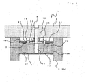
- Fig. 6 is a figure showing the state of trough 3 and lid 5 fixed, using fixing bracket 7, and is an A-A line sectional view of Fig. 2 .
- Positioning lug 21 of fixing bracket 7 fits into slot (hollow) 27 of projection part 11 as above-mentioned.
- bolt hole 13 of lid 5, bolt penetration part 25 of projection part 11, cutout 23 of fixing bracket 7, and nut part 19 are located in an approximately straight line in the perpendicular direction.
- Bolt 9 is inserted from the bolt hole 13 upper part, penetrates lid 5 and projection part 11, and screws together with nut part 19 of the lower part (undersurface of lower projection grasping part 15b) of fixing bracket 7. It is preferred to provide the locking part which fell by one step in a bolt hole so that the head of a bolt may not protrude above the lid upper surface as shown in Fig. 6 . As illustrated, in the state of fixing bracket 7 attached to projection part 11, it is preferable for the upper surface (undersurface of lid 5) of trough 3 and the upper surface of fixing bracket 7 to be approximately in agreement.
- Fig. 7 is a figure showing the state where trough 3 and lid 5 were fixed, using fixing bracket 7, and is a B-B line sectional view of Fig. 2 .
- concrete 29 is poured around trough 3 and lid 5 (left side in the figure), for example.
- trough 3 is laid underground and the gap which can insert the conventional metal fittings etc. is not formed in the circumference of trough 3. Even if it is in such a state, it is possible to open and close lid 5 with bolt 9.
- lid 5 can be easily fixed to trough 3. Since nut part 19 is fixed to lower projection grasping part 15b by welding and the like, even if bolt 9 is fastened tightly, nut part 19 does not rotate or fall out.
- Fig. 8 (A) is a decomposed perspective view showing fixing bracket 30, and Fig. 8 (B) is an assembly perspective view showing fixing bracket 30.
- the composition which performs the same function as fixing bracket 7 the same symbols as Fig. 3 and the like are attached and the repeated explanation is omitted.
- Fixing bracket 30 differs from fixing bracket 7 in that plate member 33 to which nut part 35 was fixed is fixed to upper projection grasping part 15a. Plate member 33 is tabular and nut part 35 is fixed in the center by welding and the like. Nut part 35 can screw together with a bolt from the upper part.
- Bolt hole 37 is formed in the both sides of nut part 35 of plate member 33, and bolt hole 37 is a part where bolt 39 penetrates.
- Female screw part 31 is formed in the part corresponding to bolt hole 37 in upper projection grasping part 15a. Female screw part 31 can be screwed together with bolt 39.
- plate member 33 is fixed with bolt 39 on upper projection grasping part 15a.
- Nut part 35 may be provided in the undersurface of plate member 33, and needs to provide a hole in the part corresponding to nut part 35 of plate member 33 in this case.
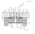
- Fig. 9 is a sectional view corresponding to Fig. 6 showing the state where lid 5 and trough 3 were fixed, using fixing bracket 30.
- Plate member 33 is attached above fixing bracket 30 with bolt 39.
- Bolt 39 is fixed to female screw part 31 formed in upper projection grasping part 15a.
- Bolt 9 inserted in bolt hole 13 of lid 5 penetrates lid 5, and is screwed together with and fixed to nut part 35.
- projection part 11 is formed in positions low by thickness, such as nut part 35, at least to the trough upper surface so that nut part 35 and the head of bolt 39 may not interfere with the undersurface of lid 5. Hence, the formation position (upper surface of a projection part) of projection part 11 is lowered by the height corresponding to nut part 35 and bolt 39 from the upper surface of trough 3.
- bolt penetration part 25 may not necessarily be required, and the simple concave part for avoiding interference with a bolt 9 tip may be sufficient, and it can also be eliminated completely.
- concave part 32 in the position corresponding to bolt 39 in the upper surface of projection part 11.
- Fig. 10 is a sectional view concerning other embodiments which fixed lid 5 and trough 3 using fixing bracket 30.
- concave part 34 which avoids interference with nut part 35 and bolt 39 may be formed in the back of lid 5 by the height corresponding to nut part 35 and bolt 39. Also by concave part 34, interference of the undersurface of lid 5, and nut part 35 and the head of bolt 39 can be prevented.
- fixing bracket 30 concerning a 2nd embodiment, it can use like fixing bracket 7 and the same effect can be performed. Since only nut part 35 (plate member 33) can be replaced from the upper part even when a nut part should be damaged, replacement work is easy.
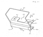
- FIG. 11 is a perspective view showing fixing bracket 40.
- Fixing brackets 40 differ in that hook 43 is provided to fixing bracket 7.
- Hook suspending part 41 is formed in connecting part 17.
- Hook suspending part 41 is a part which is formed so that it may bulge on the outside of connecting part 41, and is attached so that rotation of hook 43 is possible.
- Hook 43 is, for example, the metallic member whose tip is bent almost perpendicularly, and can lock lid 5. Hence, if hook 43 is located in substantial verticality from hook suspending part 41, the tip of hook 43 is placed so that lid 5 is pressed down from the upper part.
- buckle slot 14 ( Fig. 1 and Fig. 2 ) is formed in the position corresponding to fixing bracket 40 of lid 5, by closing lid 5 and rotating hook 43 up where fixing bracket 40 is attached to projection part 11, the tip of hook 43 can fit into buckle slot 14, and lid 5 can be certainly fixed.
- fixing bracket 40 concerning a 3rd embodiment, the same effect as fixing bracket 7 can be acquired.
- lid 5 is fixed using nut part 19, when a gap exists in the circumference, after placing a cable, lid 5 can be fixed by hook 43.
- fixing bracket 40 may be attached to a trough after removing hook 43 beforehand, and the whole hook 43 may be laid underground with concrete.
- lid 5 In order to fill up the circumference of trough 3 with gravel and the like, after fixing lid 5 by hook 43, the circumference of trough 3 is filled up with gravel and the like. To open lid 5, it is necessary to remove some surrounding gravels in the rotation movable range of hook 43, but lid 5 can more certainly be fixed. Especially when thinking security as important, both fixing of a lid with a bolt and a nut and fixing of the lid by hook can be performed. Especially when thinking security as important, both fixing of a lid with a bolt and a nut and fixing of the lid by hook are performed.
- Fig. 12 is a figure showing a reference example that does not fall within the scope of the claims in which a fixing bracket 7a with which usual nut (penetration nut) 19a is provided, Fig. 12 (a) is a top view and Fig. 12 (b) is an F-F line sectional view of Fig. 12 (a) .
- Fixing bracket 7a can be used like fixing bracket 7. Incursion of concrete at the time of pouring of concrete can be prevented by putting the cap made of an elastic material on nut part 19a, or applying grease with high viscosity to a nut.
- Fixing bracket 7b which provided nut part 19a (19) on both of upper surface of upper projection grasping part 15a and undersurface of lower projection grasping part 15b can also be used.
- Fig. 13 is a figure showing fixing bracket 7b on which nut part 19a was provided upward and downward
- Fig. 13 (a) is a top view
- Fig. 13 (b) is a G-G line sectional view of Fig. 13 (a) .
- Fixing bracket 7b can be used like fixing bracket 7.
- Nut part 19 which is a domed cap nut may be applied to downward nut part 19a.
- Fixing bracket 7c where the nut part is directly formed on upper projection grasping part 15a and lower projection grasping part 15b can also be used.
- Fig. 14 is a figure showing fixing bracket 7c where a female screw part is provided on upper projection grasping part 15a and lower projection grasping part 15b, and nut part 19b is formed
- Fig. 14 (a) is a top view
- Fig. 14 (b) is a H-H line sectional view of Fig. 14 (a)
- Nut part 19b is a female screw part formed in upper projection grasping part 15a and lower projection grasping part 15b, and can be screwed together with bolts 9 ( Fig. 1 etc.).
- Fixing bracket 7c can be used like fixing bracket 7.
- Nut part 19b may be formed only in the upper projection grasping part 15a.
- Fixing bracket 7d with which nut part 19a is provided in lower projection grasping part 15b, and plate member 33 in which nut part 35 was fixed is provided in upper projection grasping part 15a can also be used.
- Fig. 15 is a figure showing fixing bracket 7d where nut part 19a is provided in lower projection grasping part 15b, and plate member 33 is joined with bolt 39 on upper projection grasping part 15a
- Fig. 15 (a) is a top view
- Fig. 15 (b) is an I-I line sectional view of Fig. 15 (a) .
- the fixing method of plate member 33 and the like is the same as that of Fig. 8 .
- the hole where a bolt can penetrate is formed in plate member 33, upper projection grasping part 15a, and lower projection grasping part 15b.
- Fixing bracket 7d can be used like fixing bracket 7.
- a bolt may be inserted so that two nut parts or a female screw parts are penetrated, and only the nut part or female screw part formed in upper projection grasping part 15a near a lid can be fixed with a short bolt.
- nut part 19a formed in lower projection grasping part 15b
- nut part 19 which is a domed cap nut may be used, or nut part 19b where the female screw part is directly formed may be applied.
- fixing bracket 7d female screw part 31 which can detach and attach plate member 33 is beforehand provided in upper projection grasping part 15a, at the time of installation of a trough, and plate member 33 is removed, bolt 9 is fixed only by lower projection grasping part 15b, when nut part 19a of lower projection grasping part 15b is damaged, the fixing structure of lid 5 should also be repaired by attaching plate member 33 which has nut part 35 and bolt hole 37 to a fixing bracket.
- the most preferable structure is the structure where the nut part was formed in the lower projection grasping part 15b side at least.
- the nut part was formed in the lower projection grasping part 15b side and bolt 9 is fastened from the upper part, in connection with the fastening of a bolt, lower projection grasping part 15b is forced strongly up (projection part side), and the grasp force against the projection part of the fixing bracket becomes strong.
- Fig. 16 is a figure showing the shape of the tool fitting part of the head of a bolt. If bolt 9 which has the usual hexagonal tool fitting part 10 is used as shown in Fig. 16 (a) , bolt 9 can be rotated using the conventional hexagonal wrench.
- bolt 9a which has a pentagonal tool fitting part 10a may be used, or, as shown in Fig. 16 (c) , bolt 9b which has a star shaped tool fitting part 10b may be used.
- shape of a tool fitting part into the special shape instead of shapes, such as a hexagon, the usual plus or minus, specialized tools, such as a pentagon, are needed corresponding to a tool fitting part.
- a specialized tool since only a lid is not fixed, but removing a lid with a mischief and the like can be prevented, doing in this way is more preferred.
- the shape of a tool fitting part is not restricted to the example shown in Fig. 16 .
Landscapes
- Laying Of Electric Cables Or Lines Outside (AREA)
- Electric Cable Installation (AREA)
Claims (8)
- Structure de fixation d'une cuve (3) qui comprend un fond (3a) ainsi que des parois latérales (3b) prévues de part et d'autre du fond, et un couvercle (5) disposé sur l'ouverture du haut de la cuve au moyen d'un support de fixation (7), caractérisée en ce que
un élément en saillie (11) est formé vers l'extérieur dans les deux côtés des parois latérales près de l'extrémité au haut de la cuve;
un trou de pénétration pour boulon (25) est formé dans l'élément en saillie;
le support de fixation comporte des éléments d'accrochage en saillie du haut et du bas (15a, 15b) servant à saisir l'élément en saillie sur les côtés du haut et du bas, et un élément de raccordement (17) servant à raccorder les éléments d'accrochage en saillie du haut et du bas;
un écrou à chapeau (10) est fixé sur le côté iinférieur de l'élément d'accrochage en saillie du bas;
une patte de positionnement (21) faisant saillie à l'intérieur est formée au moins sur l'un des côtés intérieurs des éléments d'accrochage en saillie du haut et du bas (15b) du support de fixation;
une rainure (27) est prévue dans la position qui correspond à la patte de positionnement du support de fixation dans la partie en saillie de la cuve;
la patte de positionnement est insérée dans la rainure, et le support de fixation est fixé à la cuve des deux côtés de manière à ce que l'élément en saillie soit saisi par les éléments d'accrochage en saillie du haut et du bas;
et
il est prévu un boulon (9) qui pénètre dans le couvercle à partir du haut du couvercle à l'endroit où le couvercle est fermé, et le couvercle est fixé à la cuve par vissage du boulon dans l'écrou à chapeau. - Structure de fixation d'une cuve (3) qui comprend un fond (3a) ainsi que des parois latérales (3b) prévues de part et d'autre du fond, et un couvercle (5) placé sur l'ouverture du haut de la cuve au moyen du support de fixation (7), caractérisée en ce que un élément en saillie (11) est formé vers l'extérieur dans les deux côtés des parois latérales près de l'extrémité au haut de la cuve;
le support de fixation comporte des éléments d'accrochage en saillie du haut et du bas (15a, 15b) servant à saisir l'élément en saillie sur les côtés du haut et du bas, et un élément de raccordement (17) servant à raccorder les éléments d'accrochage en saillie du haut et du bas;
un écrou (35) est fixé sur la surface supérieure de l'élément d'accrochage en saillie du haut;;
une patte de positionnement (21) faisant saillie à l'intérieur est formée au moins sur l'un des côtés intérieurs des éléments d'accrochage en saillie du haut et du bas du support de fixation;
une rainure (27) est prévue dans la position qui correspond à la patte de positionnement du support de fixation dans la partie en saillie de la cuve;
la patte de positionnement est insérée dans la rainure, et le support de fixation est fixé à la cuve des deux côtés de manière à ce que l'élément en saillie soit saisi par les éléments d'accrochage en saillie du haut et du bas;
il est prévu un boulon (9) qui pénètre dans le couvercle à partir du haut du couvercle à l'endroit où le couvercle est fermé, et le couvercle est fixé à la cuve par vissage du boulon dans l'écrou; et
une partie concave évitant de gêner le boulon est formée dans la position qui correspond au boulon dans la surface supérieure de l'élément en saillie. - Structure de fixation d'une cuve et couvercle selon l'une quelconque des revendications 1 et 2, caractérisés en ce que la cuve est placée dans le sol de manière à ce que la surface supérieure de la cuve, lorsque le couvercle est fermé, se trouve approximativement à la hauteur du sol qui l'entoure
- Structure de fixation d'une cuve et couvercle selon la revendication 2, caractérisés en ce que l'écrou (35) est une vis femelle formée dans l'élément d'accrochage en saillie du haut (15a).
- Structure de fixation d'une cuve et couvercle selon la revendication 2, caractérisés en ce que l'écrou est raccordé à une plaque (33), et en ce que cette plaque à laquelle l'écrou se trouve raccordé est fixée à l'élément d'accrochage en saillie du haut (15a) au moyen d'un boulon (39).
- Structure de fixation d'une cuve et couvercle selon l'une quelconque des revendications 1 et 2, caractérisés en ce qu'un crochet (43), servant à verrouiller le couvercle de l'extérieur, est formé dans l'élément de raccordement.
- Procédé de fixation d'une cuve (3) qui comprend un fond (3a) ainsi que des parois latérales (3b) prévues de part et d'autre du fond, et un couvercle (5) disposé sur l'ouverture du haut de la cuve au moyen du support de fixation (7), caractérisée en ce que:un élément en saillie (11) est formé vers l'extérieur dans les deux côtés des parois latérales près de l'extrémité au haut de la cuve;un trou de pénétration pour boulon est formé dans l'élément en saillie;le support de fixation comporte des éléments d'accrochage en saillie du haut et du bas (15a, 15b) servant à saisir l'élément en saillie sur les côtés du haut et du bas, un élément de raccordement (17) servant à raccorder les éléments d'accrochage en saillie du haut etdu bas, et un écrou à chapeau (19) prévu dans le côté inférieur de l'élément d'accrochage en saillie du bas (15b);une patte de positionnement (21) faisant saillie à l'intérieur est formée au moins sur l'un des côtés intérieurs des éléments d'accrochage en saillie du haut et/ou du bas du support de fixation, et une rainure (27) est prévue dans le sens de montage du support de fixation au niveau de l'élément qui correspond à la patte de positionnement dans l'élément en saillie de la cuve;à partir des deux côtés de l'élément en saillie, la patte de positionnement est insérée le long de la rainure, et le support de fixation est fixé à l'élément en saillie de la cuve; etdu béton est coulé à l'extérieur de la cuve;il est prévu un boulon (9) qui pénètre dans le couvercle à partir du haut du couvercle à l'endroit où le couvercle est fermé, et le couvercle est fixé à la cuve par vissage du boulon dans l'écrou à chapeau.
- Procédé de fixation d'une cuve (3) qui comprend un fond (3a) ainsi que des parois latérales (3b) prévues de part et d'autre du fond, et un couvercle (5) disposé sur l'ouverture du haut de la cuve au moyen du support de fixation (7), caractérisé en ce que un élément en saillie (11) est formé vers l'extérieur dans les deux côtés des parois latérales près de l'extrémité au haut de la cuve;
le support de fixation comporte des éléments d'accrochage en saillie du haut et du bas (15a, 15b) servant à saisir l'élément en saillie des côtés supérieur et inférieur, un élément de raccordement (17) servant à raccorder les éléments d'accrochage en saillie du haut et du bas, et un écrou (35) prévu dans la surface supérieure de l'élément d'accrochage en saillie du haut;
une partie concave, évitant de gêner le boulon vissé dans l'écrou, est formée dans la position qui correspond au boulon dans la surface supérieure de l'élément en saillie;
une patte de positionnement (21) faisant saillie à l'intérieur est formée au moins sur l'un des côtés intérieurs des éléments d'accrochage en saillie du haut et/ou du bas du support de fixation, et une rainure (27) est prévue dans le sens de montage du support de fixation au niveau de l'élément qui correspond à la patte de positionnement dans l'élément en saillie de la cuve;
à partir des deux côtés de l'élément en saillie, la patte de positionnement est insérée le long de la rainure, et le support de fixation est fixé à l'élément en saillie de la cuve;
du béton est coulé à l'extérieur de la cuve; et
il est prévu le boulon (9) qui pénètre dans le couvercle à partir du haut du couvercle à l'endroit où le couvercle est fermé, et le couvercle est fixé à la cuve par vissage du boulon dans l'écrou.
Applications Claiming Priority (1)
| Application Number | Priority Date | Filing Date | Title |
|---|---|---|---|
| PCT/JP2010/053082 WO2011104863A1 (fr) | 2010-02-26 | 2010-02-26 | Structure de fixation pour cuve et couvercle, ainsi que procédé de fixation pour cuve et couvercle |
Publications (3)
| Publication Number | Publication Date |
|---|---|
| EP2541713A1 EP2541713A1 (fr) | 2013-01-02 |
| EP2541713A4 EP2541713A4 (fr) | 2014-04-02 |
| EP2541713B1 true EP2541713B1 (fr) | 2015-05-13 |
Family
ID=44357524
Family Applications (1)
| Application Number | Title | Priority Date | Filing Date |
|---|---|---|---|
| EP20100846527 Active EP2541713B1 (fr) | 2010-02-26 | 2010-02-26 | Structure de fixation pour cuve et couvercle, ainsi que procédé de fixation pour cuve et couvercle |
Country Status (4)
| Country | Link |
|---|---|
| EP (1) | EP2541713B1 (fr) |
| JP (1) | JP5307289B2 (fr) |
| GB (1) | GB2490747B (fr) |
| WO (1) | WO2011104863A1 (fr) |
Families Citing this family (6)
| Publication number | Priority date | Publication date | Assignee | Title |
|---|---|---|---|---|
| GB2517133B (en) * | 2013-06-27 | 2018-07-11 | Anderton Concrete Products Ltd | Device for Securing a Lid on a Cable Trough |
| BR112017000899B1 (pt) * | 2014-08-22 | 2021-06-01 | Novelis Inc | Dispositivo de transferência de metal curvilíneo |
| JP5855309B1 (ja) * | 2015-08-07 | 2016-02-09 | 古河電気工業株式会社 | ケーブル盗難防止方法、ケーブルの盗難防止構造およびトラフ線路 |
| CN107591753A (zh) * | 2017-10-18 | 2018-01-16 | 上海申捷管业科技有限公司 | 一种无群孔防腐联接板 |
| GB2593891A (en) * | 2020-04-06 | 2021-10-13 | Anderton Concrete Products Ltd | A Cable Trough Assembly |
| JP6935563B1 (ja) * | 2020-09-15 | 2021-09-15 | 古河電気工業株式会社 | 樹脂製のトラフ本体へのグレーチング蓋の取付け構造、トラフ線路、トラフ線路の形成方法及びグレーチング蓋 |
Family Cites Families (15)
| Publication number | Priority date | Publication date | Assignee | Title |
|---|---|---|---|---|
| JPS55173189U (fr) * | 1979-05-29 | 1980-12-12 | ||
| DE8111976U1 (de) * | 1981-04-22 | 1981-09-17 | Pyro-Chemtek Basel AG, 4051 Basel | Schutzvorrichtung für Kabeltrassen |
| JPS59164442A (ja) * | 1983-03-04 | 1984-09-17 | Honda Motor Co Ltd | 車両用多段変速機におけるシフト装置 |
| JPS59164442U (ja) * | 1983-04-16 | 1984-11-05 | 石井 真澄 | ケ−ブル用ダクト |
| US4594157A (en) * | 1984-12-31 | 1986-06-10 | Mcgowan Bernard J | Inlet clamp and screen |
| GB9723004D0 (en) * | 1997-11-01 | 1998-01-07 | Gordon & Co Ltd H | Trough lid connecting system |
| JP2002223027A (ja) * | 2001-01-29 | 2002-08-09 | Kyocera Corp | 光モジュール |
| JP2002233027A (ja) * | 2001-02-05 | 2002-08-16 | Ishikawajima Harima Heavy Ind Co Ltd | ケーブルダクト |
| US6702510B2 (en) * | 2002-01-03 | 2004-03-09 | Ede Holdings, Inc. | Utility sidewalk |
| US7365269B2 (en) * | 2002-10-09 | 2008-04-29 | Prysmian Cavi E Sistemi Energia S.R.L. | Method of screening the magnetic field generated by an electrical power transmission line and electrical power transmission line so screened |
| JP4190994B2 (ja) * | 2003-09-19 | 2008-12-03 | 古河電気工業株式会社 | トラフ固定用クリップ及びこのトラフ固定用クリップを用いたトラフの蓋の装脱着方法。 |
| JP4865215B2 (ja) | 2004-12-21 | 2012-02-01 | 古河電気工業株式会社 | トラフ用蓋固定部材とトラフの固定構造及びトラフ用蓋固定部材の着脱方法 |
| JP2008199756A (ja) | 2007-02-09 | 2008-08-28 | Furukawa Electric Co Ltd:The | トラフの蓋固定金具 |
| FR2934336B1 (fr) * | 2008-07-22 | 2010-09-17 | Lisi Automotive Rapid | Dispositif de pince a ecrou pouvant etre monte sur le bord d'un panneau ou analogue |
| US7648319B1 (en) * | 2008-11-12 | 2010-01-19 | Orlando Ochoa | Clip nut fastener |
-
2010
- 2010-02-26 GB GB201109748A patent/GB2490747B/en active Active
- 2010-02-26 WO PCT/JP2010/053082 patent/WO2011104863A1/fr active Application Filing
- 2010-02-26 JP JP2012501592A patent/JP5307289B2/ja active Active
- 2010-02-26 EP EP20100846527 patent/EP2541713B1/fr active Active
Also Published As
| Publication number | Publication date |
|---|---|
| JP5307289B2 (ja) | 2013-10-02 |
| EP2541713A4 (fr) | 2014-04-02 |
| GB2490747B (en) | 2015-05-13 |
| GB2490747A8 (en) | 2012-11-28 |
| WO2011104863A1 (fr) | 2011-09-01 |
| GB2490747A (en) | 2012-11-14 |
| GB201109748D0 (en) | 2011-07-27 |
| EP2541713A1 (fr) | 2013-01-02 |
| JPWO2011104863A1 (ja) | 2013-06-17 |
Similar Documents
| Publication | Publication Date | Title |
|---|---|---|
| EP2541713B1 (fr) | Structure de fixation pour cuve et couvercle, ainsi que procédé de fixation pour cuve et couvercle | |
| US5340232A (en) | Manhole cover | |
| AU752894B2 (en) | Sump stabilizer bar | |
| US10570610B2 (en) | Profiled rail with plug for fastening to formwork | |
| US8511930B2 (en) | Cover for a road system device and corresponding road system device | |
| US4152910A (en) | Meter box guard lock | |
| JP5567204B1 (ja) | マンホール用蓋の取付け構造と取付け及び取外し方法 | |
| CN210531336U (zh) | 半圆横担抱箍 | |
| CN203866860U (zh) | 防坠井 | |
| KR200436607Y1 (ko) | 지렛대용 맨홀 뚜껑의 잠금장치 | |
| JP3142803U (ja) | 溝蓋の盗難防止装置 | |
| CN214195924U (zh) | 一种汽车用防腐锁扣板 | |
| AU2009100932A4 (en) | Cast-in plate void former | |
| JPH0780819A (ja) | コンクリートセグメントの製造装置 | |
| JP6612929B1 (ja) | マス蓋飛散防止具及びマス蓋飛散防止具の設置方法 | |
| CN103132695A (zh) | 用于悬臂爬模施工的精轧螺纹钢杆螺母组合及安装方法 | |
| CN211773915U (zh) | 一种重型井盖 | |
| CN202473081U (zh) | 一种带内衬的多功能封印 | |
| CA3032315A1 (fr) | Ensembles de cellules electrolytiques et procedes de deplacement vertical periodique | |
| JP3059954B2 (ja) | インサートブッシュ | |
| JP3277995B2 (ja) | 側溝構築時におけるグレ−チング用受枠の仮止め金具 | |
| KR200352983Y1 (ko) | 전주고정 볼트 너트 보호커버 | |
| US20110255215A1 (en) | Securing Apparatus and System | |
| CN205577281U (zh) | 连接扶手的连接座 | |
| KR200361658Y1 (ko) | 밀폐, 개폐 및 제조가 용이한 맨홀뚜껑 |
Legal Events
| Date | Code | Title | Description |
|---|---|---|---|
| PUAI | Public reference made under article 153(3) epc to a published international application that has entered the european phase |
Free format text: ORIGINAL CODE: 0009012 |
|
| 17P | Request for examination filed |
Effective date: 20120816 |
|
| AK | Designated contracting states |
Kind code of ref document: A1 Designated state(s): AT BE BG CH CY CZ DE DK EE ES FI FR GB GR HR HU IE IS IT LI LT LU LV MC MK MT NL NO PL PT RO SE SI SK SM TR |
|
| DAX | Request for extension of the european patent (deleted) | ||
| A4 | Supplementary search report drawn up and despatched |
Effective date: 20140304 |
|
| RIC1 | Information provided on ipc code assigned before grant |
Ipc: H02G 1/06 20060101ALI20140226BHEP Ipc: H02G 9/04 20060101AFI20140226BHEP |
|
| GRAP | Despatch of communication of intention to grant a patent |
Free format text: ORIGINAL CODE: EPIDOSNIGR1 |
|
| INTG | Intention to grant announced |
Effective date: 20141021 |
|
| GRAP | Despatch of communication of intention to grant a patent |
Free format text: ORIGINAL CODE: EPIDOSNIGR1 |
|
| INTG | Intention to grant announced |
Effective date: 20141201 |
|
| GRAS | Grant fee paid |
Free format text: ORIGINAL CODE: EPIDOSNIGR3 |
|
| GRAA | (expected) grant |
Free format text: ORIGINAL CODE: 0009210 |
|
| RBV | Designated contracting states (corrected) |
Designated state(s): AT BE BG CH CY CZ DE DK EE ES FI FR GR HR HU IE IS IT LI LT LU LV MC MK MT NL NO PL PT RO SE SI SK SM TR |
|
| AK | Designated contracting states |
Kind code of ref document: B1 Designated state(s): AT BE BG CH CY CZ DE DK EE ES FI FR GR HR HU IE IS IT LI LT LU LV MC MK MT NL NO PL PT RO SE SI SK SM TR |
|
| REG | Reference to a national code |
Ref country code: CH Ref legal event code: EP |
|
| REG | Reference to a national code |
Ref country code: IE Ref legal event code: FG4D |
|
| REG | Reference to a national code |
Ref country code: AT Ref legal event code: REF Ref document number: 727133 Country of ref document: AT Kind code of ref document: T Effective date: 20150615 |
|
| REG | Reference to a national code |
Ref country code: DE Ref legal event code: R096 Ref document number: 602010024687 Country of ref document: DE Effective date: 20150625 |
|
| REG | Reference to a national code |
Ref country code: AT Ref legal event code: MK05 Ref document number: 727133 Country of ref document: AT Kind code of ref document: T Effective date: 20150513 |
|
| REG | Reference to a national code |
Ref country code: NL Ref legal event code: MP Effective date: 20150513 |
|
| REG | Reference to a national code |
Ref country code: LT Ref legal event code: MG4D |
|
| PG25 | Lapsed in a contracting state [announced via postgrant information from national office to epo] |
Ref country code: PT Free format text: LAPSE BECAUSE OF FAILURE TO SUBMIT A TRANSLATION OF THE DESCRIPTION OR TO PAY THE FEE WITHIN THE PRESCRIBED TIME-LIMIT Effective date: 20150914 Ref country code: HR Free format text: LAPSE BECAUSE OF FAILURE TO SUBMIT A TRANSLATION OF THE DESCRIPTION OR TO PAY THE FEE WITHIN THE PRESCRIBED TIME-LIMIT Effective date: 20150513 Ref country code: ES Free format text: LAPSE BECAUSE OF FAILURE TO SUBMIT A TRANSLATION OF THE DESCRIPTION OR TO PAY THE FEE WITHIN THE PRESCRIBED TIME-LIMIT Effective date: 20150513 Ref country code: LT Free format text: LAPSE BECAUSE OF FAILURE TO SUBMIT A TRANSLATION OF THE DESCRIPTION OR TO PAY THE FEE WITHIN THE PRESCRIBED TIME-LIMIT Effective date: 20150513 Ref country code: NO Free format text: LAPSE BECAUSE OF FAILURE TO SUBMIT A TRANSLATION OF THE DESCRIPTION OR TO PAY THE FEE WITHIN THE PRESCRIBED TIME-LIMIT Effective date: 20150813 Ref country code: FI Free format text: LAPSE BECAUSE OF FAILURE TO SUBMIT A TRANSLATION OF THE DESCRIPTION OR TO PAY THE FEE WITHIN THE PRESCRIBED TIME-LIMIT Effective date: 20150513 |
|
| PG25 | Lapsed in a contracting state [announced via postgrant information from national office to epo] |
Ref country code: IS Free format text: LAPSE BECAUSE OF FAILURE TO SUBMIT A TRANSLATION OF THE DESCRIPTION OR TO PAY THE FEE WITHIN THE PRESCRIBED TIME-LIMIT Effective date: 20150913 Ref country code: BG Free format text: LAPSE BECAUSE OF FAILURE TO SUBMIT A TRANSLATION OF THE DESCRIPTION OR TO PAY THE FEE WITHIN THE PRESCRIBED TIME-LIMIT Effective date: 20150813 Ref country code: GR Free format text: LAPSE BECAUSE OF FAILURE TO SUBMIT A TRANSLATION OF THE DESCRIPTION OR TO PAY THE FEE WITHIN THE PRESCRIBED TIME-LIMIT Effective date: 20150814 Ref country code: AT Free format text: LAPSE BECAUSE OF FAILURE TO SUBMIT A TRANSLATION OF THE DESCRIPTION OR TO PAY THE FEE WITHIN THE PRESCRIBED TIME-LIMIT Effective date: 20150513 Ref country code: LV Free format text: LAPSE BECAUSE OF FAILURE TO SUBMIT A TRANSLATION OF THE DESCRIPTION OR TO PAY THE FEE WITHIN THE PRESCRIBED TIME-LIMIT Effective date: 20150513 |
|
| REG | Reference to a national code |
Ref country code: FR Ref legal event code: PLFP Year of fee payment: 7 |
|
| PG25 | Lapsed in a contracting state [announced via postgrant information from national office to epo] |
Ref country code: DK Free format text: LAPSE BECAUSE OF FAILURE TO SUBMIT A TRANSLATION OF THE DESCRIPTION OR TO PAY THE FEE WITHIN THE PRESCRIBED TIME-LIMIT Effective date: 20150513 Ref country code: EE Free format text: LAPSE BECAUSE OF FAILURE TO SUBMIT A TRANSLATION OF THE DESCRIPTION OR TO PAY THE FEE WITHIN THE PRESCRIBED TIME-LIMIT Effective date: 20150513 |
|
| REG | Reference to a national code |
Ref country code: DE Ref legal event code: R097 Ref document number: 602010024687 Country of ref document: DE |
|
| PG25 | Lapsed in a contracting state [announced via postgrant information from national office to epo] |
Ref country code: CZ Free format text: LAPSE BECAUSE OF FAILURE TO SUBMIT A TRANSLATION OF THE DESCRIPTION OR TO PAY THE FEE WITHIN THE PRESCRIBED TIME-LIMIT Effective date: 20150513 Ref country code: RO Free format text: LAPSE BECAUSE OF NON-PAYMENT OF DUE FEES Effective date: 20150513 Ref country code: SK Free format text: LAPSE BECAUSE OF FAILURE TO SUBMIT A TRANSLATION OF THE DESCRIPTION OR TO PAY THE FEE WITHIN THE PRESCRIBED TIME-LIMIT Effective date: 20150513 Ref country code: PL Free format text: LAPSE BECAUSE OF FAILURE TO SUBMIT A TRANSLATION OF THE DESCRIPTION OR TO PAY THE FEE WITHIN THE PRESCRIBED TIME-LIMIT Effective date: 20150513 |
|
| PLBE | No opposition filed within time limit |
Free format text: ORIGINAL CODE: 0009261 |
|
| STAA | Information on the status of an ep patent application or granted ep patent |
Free format text: STATUS: NO OPPOSITION FILED WITHIN TIME LIMIT |
|
| 26N | No opposition filed |
Effective date: 20160216 |
|
| PG25 | Lapsed in a contracting state [announced via postgrant information from national office to epo] |
Ref country code: SI Free format text: LAPSE BECAUSE OF FAILURE TO SUBMIT A TRANSLATION OF THE DESCRIPTION OR TO PAY THE FEE WITHIN THE PRESCRIBED TIME-LIMIT Effective date: 20150513 Ref country code: BE Free format text: LAPSE BECAUSE OF NON-PAYMENT OF DUE FEES Effective date: 20160229 |
|
| PG25 | Lapsed in a contracting state [announced via postgrant information from national office to epo] |
Ref country code: BE Free format text: LAPSE BECAUSE OF FAILURE TO SUBMIT A TRANSLATION OF THE DESCRIPTION OR TO PAY THE FEE WITHIN THE PRESCRIBED TIME-LIMIT Effective date: 20150513 |
|
| PG25 | Lapsed in a contracting state [announced via postgrant information from national office to epo] |
Ref country code: LU Free format text: LAPSE BECAUSE OF FAILURE TO SUBMIT A TRANSLATION OF THE DESCRIPTION OR TO PAY THE FEE WITHIN THE PRESCRIBED TIME-LIMIT Effective date: 20160226 Ref country code: MC Free format text: LAPSE BECAUSE OF FAILURE TO SUBMIT A TRANSLATION OF THE DESCRIPTION OR TO PAY THE FEE WITHIN THE PRESCRIBED TIME-LIMIT Effective date: 20150513 |
|
| REG | Reference to a national code |
Ref country code: CH Ref legal event code: PL |
|
| PG25 | Lapsed in a contracting state [announced via postgrant information from national office to epo] |
Ref country code: CH Free format text: LAPSE BECAUSE OF NON-PAYMENT OF DUE FEES Effective date: 20160229 Ref country code: LI Free format text: LAPSE BECAUSE OF NON-PAYMENT OF DUE FEES Effective date: 20160229 |
|
| REG | Reference to a national code |
Ref country code: IE Ref legal event code: MM4A |
|
| REG | Reference to a national code |
Ref country code: FR Ref legal event code: PLFP Year of fee payment: 8 |
|
| PG25 | Lapsed in a contracting state [announced via postgrant information from national office to epo] |
Ref country code: IE Free format text: LAPSE BECAUSE OF NON-PAYMENT OF DUE FEES Effective date: 20160226 |
|
| PG25 | Lapsed in a contracting state [announced via postgrant information from national office to epo] |
Ref country code: NL Free format text: LAPSE BECAUSE OF FAILURE TO SUBMIT A TRANSLATION OF THE DESCRIPTION OR TO PAY THE FEE WITHIN THE PRESCRIBED TIME-LIMIT Effective date: 20150513 Ref country code: SE Free format text: LAPSE BECAUSE OF FAILURE TO SUBMIT A TRANSLATION OF THE DESCRIPTION OR TO PAY THE FEE WITHIN THE PRESCRIBED TIME-LIMIT Effective date: 20150513 |
|
| PG25 | Lapsed in a contracting state [announced via postgrant information from national office to epo] |
Ref country code: MT Free format text: LAPSE BECAUSE OF FAILURE TO SUBMIT A TRANSLATION OF THE DESCRIPTION OR TO PAY THE FEE WITHIN THE PRESCRIBED TIME-LIMIT Effective date: 20150513 |
|
| REG | Reference to a national code |
Ref country code: FR Ref legal event code: PLFP Year of fee payment: 9 |
|
| PG25 | Lapsed in a contracting state [announced via postgrant information from national office to epo] |
Ref country code: HU Free format text: LAPSE BECAUSE OF FAILURE TO SUBMIT A TRANSLATION OF THE DESCRIPTION OR TO PAY THE FEE WITHIN THE PRESCRIBED TIME-LIMIT; INVALID AB INITIO Effective date: 20100226 Ref country code: CY Free format text: LAPSE BECAUSE OF FAILURE TO SUBMIT A TRANSLATION OF THE DESCRIPTION OR TO PAY THE FEE WITHIN THE PRESCRIBED TIME-LIMIT Effective date: 20150513 Ref country code: SM Free format text: LAPSE BECAUSE OF FAILURE TO SUBMIT A TRANSLATION OF THE DESCRIPTION OR TO PAY THE FEE WITHIN THE PRESCRIBED TIME-LIMIT Effective date: 20150513 |
|
| PG25 | Lapsed in a contracting state [announced via postgrant information from national office to epo] |
Ref country code: MT Free format text: LAPSE BECAUSE OF FAILURE TO SUBMIT A TRANSLATION OF THE DESCRIPTION OR TO PAY THE FEE WITHIN THE PRESCRIBED TIME-LIMIT Effective date: 20160229 Ref country code: MK Free format text: LAPSE BECAUSE OF FAILURE TO SUBMIT A TRANSLATION OF THE DESCRIPTION OR TO PAY THE FEE WITHIN THE PRESCRIBED TIME-LIMIT Effective date: 20150513 Ref country code: TR Free format text: LAPSE BECAUSE OF FAILURE TO SUBMIT A TRANSLATION OF THE DESCRIPTION OR TO PAY THE FEE WITHIN THE PRESCRIBED TIME-LIMIT Effective date: 20150513 |
|
| PGFP | Annual fee paid to national office [announced via postgrant information from national office to epo] |
Ref country code: FR Payment date: 20220118 Year of fee payment: 13 |
|
| PGFP | Annual fee paid to national office [announced via postgrant information from national office to epo] |
Ref country code: IT Payment date: 20230110 Year of fee payment: 14 |
|
| P01 | Opt-out of the competence of the unified patent court (upc) registered |
Effective date: 20230512 |
|
| PGFP | Annual fee paid to national office [announced via postgrant information from national office to epo] |
Ref country code: DE Payment date: 20231229 Year of fee payment: 15 |