EP2540621B1 - Control system of aircraft, method for controlling aircraft, and aircraft - Google Patents
Control system of aircraft, method for controlling aircraft, and aircraft Download PDFInfo
- Publication number
- EP2540621B1 EP2540621B1 EP11747492.4A EP11747492A EP2540621B1 EP 2540621 B1 EP2540621 B1 EP 2540621B1 EP 11747492 A EP11747492 A EP 11747492A EP 2540621 B1 EP2540621 B1 EP 2540621B1
- Authority
- EP
- European Patent Office
- Prior art keywords
- control
- aircraft
- thrust
- control signal
- engine
- Prior art date
- Legal status (The legal status is an assumption and is not a legal conclusion. Google has not performed a legal analysis and makes no representation as to the accuracy of the status listed.)
- Active
Links
- 238000000034 method Methods 0.000 title claims description 8
- 230000007257 malfunction Effects 0.000 claims description 29
- 238000001514 detection method Methods 0.000 claims description 8
- 238000001914 filtration Methods 0.000 claims description 2
- RZVHIXYEVGDQDX-UHFFFAOYSA-N 9,10-anthraquinone Chemical compound C1=CC=C2C(=O)C3=CC=CC=C3C(=O)C2=C1 RZVHIXYEVGDQDX-UHFFFAOYSA-N 0.000 description 26
- 230000000694 effects Effects 0.000 description 8
- 230000007423 decrease Effects 0.000 description 3
- 230000001133 acceleration Effects 0.000 description 2
- 238000010586 diagram Methods 0.000 description 2
- 230000005856 abnormality Effects 0.000 description 1
- 230000003247 decreasing effect Effects 0.000 description 1
- 239000000446 fuel Substances 0.000 description 1
- 239000007789 gas Substances 0.000 description 1
- 238000012423 maintenance Methods 0.000 description 1
- 238000005096 rolling process Methods 0.000 description 1
Images
Classifications
-
- B—PERFORMING OPERATIONS; TRANSPORTING
- B64—AIRCRAFT; AVIATION; COSMONAUTICS
- B64C—AEROPLANES; HELICOPTERS
- B64C13/00—Control systems or transmitting systems for actuating flying-control surfaces, lift-increasing flaps, air brakes, or spoilers
- B64C13/02—Initiating means
- B64C13/16—Initiating means actuated automatically, e.g. responsive to gust detectors
-
- B—PERFORMING OPERATIONS; TRANSPORTING
- B64—AIRCRAFT; AVIATION; COSMONAUTICS
- B64D—EQUIPMENT FOR FITTING IN OR TO AIRCRAFT; FLIGHT SUITS; PARACHUTES; ARRANGEMENTS OR MOUNTING OF POWER PLANTS OR PROPULSION TRANSMISSIONS IN AIRCRAFT
- B64D31/00—Power plant control; Arrangement thereof
- B64D31/02—Initiating means
- B64D31/06—Initiating means actuated automatically
Definitions
- the present invention relates to an aircraft control system, a method for controlling an aircraft, and an aircraft, and particularly relates to an aircraft control system, a method for controlling an aircraft, and an aircraft that enable stable flight even when part or all of control surfaces are in a malfunctioning state, for example, an inoperative state or a damaged state.
- the attitude of aircraft is controlled by an actuator appropriately moving control surfaces such as elevators, ailerons, and a rudder in accordance with a predetermined control signal.
- a controlling computer mounted on an aircraft calculates a deflection angle control signal for controlling control surfaces based on information detected from various sensors such as an inertial sensor and an air data sensor provided on the aircraft and an operation command signal from an operation end such as a control wheel.
- the actuator then moves the control surfaces in accordance with the deflection angle control signal calculated by the controlling computer, thereby maintaining the aircraft in a desired attitude and achieving stable flight.
- Patent Literature 1 Japanese Unexamined Patent Application, Publication No. Hei 8-183497 discloses a control method in which a thrust vectoring means that generates a moment in the yaw direction by deflecting jet exhaust is provided, and control by a rudder is switched to control by the thrust vectoring means if it is judged that the rudder does not function normally.
- Patent Literature 1 has problems of an increase in the number of aircraft components, an increase in weight, and an increase in the number of portions that require maintenance because it is necessary to separately provide the thrust vectoring means.
- the present invention has been made to solve the above-described problems, and it is an object thereof to provide an aircraft control system that enables stable flight without the need for a complicated throttle operation by the pilot even when part or all of control surfaces malfunction.
- the present invention employs the following solutions.
- the present invention provides an aircraft control system according to claim 1 including a computation means that calculates a thrust control signal for controlling engine thrust and a deflection angle control signal for controlling control surfaces based on state information indicating a state of an airframe and an operation command signal from a vehicle control unit, an engine driving means that drives an engine based on the thrust control signal, and a control surface moving means that moves the control surfaces based on the deflection angle control signal.
- the computation means acquires various types of state information regarding the state of the airframe, such as the angular speed, the attitude angle, the acceleration, the angle of attack, the angle of sideslip, the pressure altitude, and the airspeed of the airframe, from an inertial sensor, an air data sensor, and the like that are provided on the airframe, and also acquires an operation command signal generated by the pilot operating the vehicle control unit such as a control wheel. Then, to control the airframe to keep it in a desired attitude, the computation means calculates a thrust control signal for controlling engine thrust and a deflection angle control signal for controlling the control surfaces based on the state information and the operation command signal.
- state information regarding the state of the airframe such as the angular speed, the attitude angle, the acceleration, the angle of attack, the angle of sideslip, the pressure altitude, and the airspeed of the airframe.
- the engine driving means drives the engine based on the thrust control signal
- the control surface moving means moves the control surfaces based the deflection angle control signal.
- control of engine thrust is performed by driving the engine based on the thrust control signal.
- An aircraft control system includes a control surface operating state detection means that detects that at least one of the control surfaces malfunctions, wherein the computation means calculates the thrust control signal and the deflection angle control signal if it is detected that at least one of the control surfaces malfunctions.
- the airframe is controlled by means of the engine thrust if there is a malfunction in the control surfaces, and therefore, stable flight can be continued at all times.
- the response speed is less than that when the airframe is controlled by means of the control surfaces.
- the airframe is controlled by means of engine thrust only when part or all of the control surfaces malfunction, and thus, the airframe can be more accurately controlled and stable flight can be continued at all times.
- An aircraft control system includes an alarm means that detects that at least one of the control surfaces malfunctions and informs a pilot to that effect.
- the pilot since the pilot is informed of the fact that at least one of the control surfaces malfunctions, the pilot can be expected to take an appropriate action, and therefore, the airframe can be more accurately controlled and stable flight can be continued.
- An aircraft control system includes a response adjustment filter that adjusts response speed of the engine and the control surfaces.
- the speed of the response of the airframe when controlled by means of the engine thrust and the response of the airframe when controlled by means of the control surfaces can be adjusted by the response adjustment filter, and this can contribute to continuation of stable flight.
- the response speed of the airframe when controlled by means of engine thrust is slower than the response speed of the airframe when controlled by means of the deflection angle.
- the response speed varies depending on which portion of the control surfaces malfunctions. For this reason, the deflection angle control signal is filtered by the response adjustment filter to make the response speed of the control surfaces almost equal to the response speed of the engine.
- the variation in the response speed can be suppressed, and this can contribute to continuation of stable flight.
- the present invention provides an aircraft including the above-described aircraft control system.
- the airframe can be changed to or maintained in a desired attitude by performing control of engine thrust by driving the engine based on the thrust control signal, in addition to control of the deflection angle that is performed by moving the control surfaces, and therefore, stable flight can be continued without the need for a complicated throttle operation by the pilot.
- the present invention provides a method for controlling an aircraft according to claim 5, the method including the steps of calculating a thrust control signal for controlling engine thrust and a deflection angle control signal for controlling control surfaces based on state information indicating the state of an airframe of an aircraft and an operation command signal from a vehicle control unit, driving an engine based on the thrust control signal, and moving the control surfaces based on the deflection angle control signal.
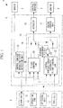
- FIG. 1 is a block diagram schematically showing the configuration of an aircraft control system according to an embodiment of the present invention in a state in which the control system is applied to an aircraft.
- FIG. 1 is a block diagram schematically showing the configuration of an aircraft 1 to which the aircraft control system according to the present embodiment is applied.
- the aircraft 1 includes a sensor 2, control surfaces 3, an engine 4, a cockpit 5, and a control system 6.
- the sensor 2 includes various sensors such as an inertial sensor and an air data sensor, and acquires various types of state information regarding the state of an airframe, such as the angular speed, the attitude angle, the acceleration, the angle of attack, the angle of sideslip, the pressure altitude, and the airspeed of the airframe, and outputs the acquired state information to the control system 6.
- various sensors such as an inertial sensor and an air data sensor, and acquires various types of state information regarding the state of an airframe, such as the angular speed, the attitude angle, the acceleration, the angle of attack, the angle of sideslip, the pressure altitude, and the airspeed of the airframe, and outputs the acquired state information to the control system 6.
- the control surfaces 3 include an elevator that moves the nose of the aircraft up or down, a rudder that changes the direction that the nose of the aircraft is pointing to left or right, an aileron that banks the airframe left or right, and a high-lift device (flap) that rectifies the airfoil of a main wing to increase lift.
- An actuator which will be described later, moves the control surfaces 3, and thus, the attitude of the airframe is controlled by means of an aerodynamic force.
- the engine 4 which may be a jet engine, is driven by an engine control unit, which will be described later, to produce thrust as a reaction to a high-speed discharge of gases generated by burning fuel with air drawn therein.
- instruments that indicate the flight conditions of the aircraft 1 are disposed, and as shown in FIG. 1 , various types of equipment for enabling the pilot to control the aircraft 1, such as an operation end 10, a throttle 11, a alarm unit 12, and a switching unit 13, are disposed.
- the pilot operates the operation end 10 to control the control surfaces 3, and an operation command signal for controlling the control surfaces that is generated by the pilot operating the operation end 10 is output to the control system 6.
- the pilot operates the throttle 11 to control engine thrust, and an operation command signal for controlling engine thrust that is generated by the pilot operating the throttle 11 is output to the control system 6.
- the alarm unit 12 makes a buzzing sound or performs a display on a display unit (not shown) provided within the cockpit 5 to inform the pilot of a predetermined warning based on information from the control system 6.
- the alarm unit 12 informs the pilot to that effect.
- the switching unit 13 outputs a switching command signal for switching a flight control law 20 and a control surface/thrust integrated flight control law 22 (described in detail later) of the control system 6, and the switching command signal is output to the control system 6 based on an operation by the pilot.
- the control system 6 includes a computer 15 for computing a predetermined control signal, an actuator 16 that moves the control surfaces 3 based on the control signal output from the computer 15, an engine control unit 17 that similarly drives the engine 4 based on the control signal output from the computer 15, and a control surface operating state detection unit 18 that detects an operating state of the control surfaces.
- the computer 15 computes a deflection angle control signal and a thrust control signal, and includes the flight control law 20, the control surface/thrust integrated flight control law 22, and a switch 19 for switching between these two laws.
- the flight control law 20 is a flight control law for enabling the aircraft 1 to be flown automatically or manually by the pilot in a state in which the aircraft 1 is flying normally with its equipment such as the control surfaces 3 functioning normally.
- the computer 15 In a state in which the aircraft 1 is controlled based on the flight control law 20, to control especially the attitude of the aircraft 1, the computer 15 generates a deflection angle control signal based on the operation command signal from the pilot via the operation end 10 and the state information from the sensor 2. Every generated deflection angle control signal is output to the actuator 16, and the actuator 16 moves the control surfaces 3 in accordance with the deflection angle control signal to control the deflection angle, thereby changing or maintaining the attitude of the aircraft 1.
- the control surface/thrust integrated flight control law 22 is a flight control law for enabling the aircraft 1 to be flown automatically or manually by the pilot when any of the control surfaces 3 of the aircraft 1 malfunctions.
- the computer 15 In a state in which the aircraft 1 is controlled based on the control surface/thrust integrated flight control law 22, to control the attitude of the aircraft 1, the computer 15 generates a deflection angle control signal and a thrust control signal based on the operation command signal from the pilot via the operation end 10 and the state information from the sensor 2.
- the computer 15 since the thrust control signal is computed based on the operation command signal and the state information, even when the throttle 11 is operated, the computer 15 restricts the effect of this operation and automatically puts high priority on computation of the thrust control signal based on the operation command signal and the state information.
- the generated deflection angle control signal is output to the actuator 16, and the actuator 16 moves the control surfaces 3 in accordance with the deflection angle control signal.
- the generated thrust control signal is output to the engine control unit 17, and the engine control unit 17 drives the engine 4 in accordance with the thrust control signal.
- a response adjustment filter 23 for adjusting the difference in response speed between the engine 4 and the control surfaces 3 is provided on a path over which the deflection angle control signal is output from the control surface/thrust integrated flight control law 22 to the actuator 16. According to the invention, the response adjustment filter 23 performs response speed adjustment by filtering the deflection angle control signal.
- the response speed from when a thrust control signal is output to control engine thrust until when the engine 4 outputs engine thrust based on that thrust control signal is slower than the response speed from when a deflection angle control signal is output to control the deflection angle until when the control surfaces 3 reach a deflection angle based on that deflection angle control signal.
- the response speed of the airframe varies depending on which portion of the control surfaces 3 malfunctions.
- the response adjustment filter 23 is provided to perform adjustment so as to make the response speed of the control surfaces 3 almost equal to the response speed of the engine 4, thereby achieving a uniform response speed of the airframe regardless of which portion of the control surfaces 3 malfunctions.
- the control surface operating state detection unit 18 judges whether the control surfaces 3 function normally based on the state information regarding the aircraft 1 output from the sensor 2, detects a malfunction if any or all of the control surfaces 3 are inoperative or damaged, and outputs a malfunction signal to that effect to the alarm unit 12 and the computer 15. Moreover, the control surface operating state detection unit 18 outputs a switching signal to the computer 15 when the flight control law 20 and the control surface/thrust integrated flight control law 22 of the computer 15 are to be automatically switched in a state in which the malfunction of the control surfaces 3 has been detected.
- the switch 19 is adapted to switch between the flight control law 20 and the control surface/thrust integrated flight control law 22 as appropriate in response to either the switching command signal from the switching unit 13 based on an instruction from the pilot or the switching signal from the control surface operating state detection unit 18, depending on the state of the aircraft 1.
- the aircraft 1 When there is no abnormality in the equipment such as the control surfaces 3 of the above-described aircraft 1, the aircraft 1 flies under control based on the flight control law 20. During the flight, if the control surface operating state detection unit 18 detects that at least one of the control surfaces 3 malfunctions for some reason such as damage, the control surface operating state detection unit 18 outputs a malfunction signal to that effect to the alarm unit 12 and a switching signal to the computer 15. Once the pilot of the aircraft 1 recognizes the malfunction of the control surfaces 3 as a result of the malfunction signal being output to the alarm unit 12, the pilot operates the switching unit 13 to switch to the control surface/thrust integrated flight control law 22, and the switching unit 13 outputs a switching command signal. The computer 15 drives the switch 19 based on the switching command signal to switch the flight control law so that the aircraft 1 is controlled based on the control surface/thrust integrated flight control law 22 as shown in FIG. 1 .
- the computer 15 based on the control surface/thrust integrated flight control law 22, generates a deflection angle control signal that turns the trailing edge of the aileron on the port side upward and computes a thrust control signal that decreases engine thrust of an engine on the port side while increasing engine thrust of an engine on the starboard side.
- the control surfaces 3 and the engine 4 being moved or driven in accordance with these control signals, the lift on the main wing on the port side is decreased and a yawing moment for left yaw is generated to produce an angle of sideslip, and a rolling moment due to a dihedral effect is generated, and thus, the airframe can be rolled to the left at the desired speed.
- the computer 15 when it is desired to lower the nose, if all of the control surfaces 3 function normally, it is possible to easily lower the nose by moving elevators, while if there is a malfunction in the elevators, the computer 15 generates a thrust control signal that decreases engine thrust of the left and right engines at the same time. This enables control in the pitch direction to be performed by means of the engines, and thus, the nose can be lowered.
- control of engine thrust is also performed in addition to control of the deflection angle that is performed by moving the control surfaces 3, even when part or all of the control surfaces 3 malfunction and the control surfaces 3 do not function normally, that is, when it is difficult to control the airframe attitude using the control surfaces, this problem is compensated for by computing a thrust control signal for controlling the engine thrust automatically and thereby controlling the engine thrust.
- the airframe can be changed to or maintained in a desired attitude without the need for a complicated throttle operation by the pilot, and stable flight can therefore be continued.
- the computer 15 can of course perform switching between the flight control law 20 and the control surface/thrust integrated flight control law 22 via the switch 19 by software, it may include separate and independent computing devices that compute a deflection angle control signal and a thrust control signal, respectively, and perform switching between the flight control law 20 and the control surface/thrust integrated flight control law 22 via the switch 19 by hardware.
Applications Claiming Priority (2)
| Application Number | Priority Date | Filing Date | Title |
|---|---|---|---|
| JP2010043521A JP5123964B2 (ja) | 2010-02-26 | 2010-02-26 | 航空機の制御システム、航空機の制御方法、及び航空機 |
| PCT/JP2011/054253 WO2011105536A1 (ja) | 2010-02-26 | 2011-02-25 | 航空機の制御システム、航空機の制御方法、及び航空機 |
Publications (3)
| Publication Number | Publication Date |
|---|---|
| EP2540621A1 EP2540621A1 (en) | 2013-01-02 |
| EP2540621A4 EP2540621A4 (en) | 2018-01-17 |
| EP2540621B1 true EP2540621B1 (en) | 2020-03-18 |
Family
ID=44506933
Family Applications (1)
| Application Number | Title | Priority Date | Filing Date |
|---|---|---|---|
| EP11747492.4A Active EP2540621B1 (en) | 2010-02-26 | 2011-02-25 | Control system of aircraft, method for controlling aircraft, and aircraft |
Country Status (8)
| Country | Link |
|---|---|
| US (1) | US9045220B2 (ru) |
| EP (1) | EP2540621B1 (ru) |
| JP (1) | JP5123964B2 (ru) |
| CN (1) | CN102695649B (ru) |
| BR (1) | BR112012015965A2 (ru) |
| CA (1) | CA2785692C (ru) |
| RU (1) | RU2537883C2 (ru) |
| WO (1) | WO2011105536A1 (ru) |
Families Citing this family (18)
| Publication number | Priority date | Publication date | Assignee | Title |
|---|---|---|---|---|
| FR2970702B1 (fr) * | 2011-01-26 | 2013-05-10 | Astrium Sas | Procede et systeme de pilotage d'un engin volant a propulseur arriere |
| JP5812633B2 (ja) * | 2011-03-14 | 2015-11-17 | 三菱重工業株式会社 | 航空機の制御システム、航空機、航空機の制御プログラム、及び航空機の制御方法 |
| CN103057712B (zh) * | 2012-12-31 | 2015-06-17 | 北京航空航天大学 | 微小型飞行机器人集成飞行控制系统 |
| CN103324202A (zh) * | 2013-07-12 | 2013-09-25 | 无锡华航电子科技有限责任公司 | 基于舵面故障的容错飞行控制系统和方法 |
| CN104477376B (zh) * | 2014-12-23 | 2016-08-24 | 北京航空航天大学 | 一种高超声速飞行器气动舵/反作用控制系统复合气动控制方法 |
| RU171721U1 (ru) * | 2016-03-30 | 2017-06-13 | Общество с ограниченной ответственностью "Научно-инженерная компания "Объектные системы автоматики" (ООО "НИК "ОСА") | Система управления основными летными функциями самолета с помощью рулевых поверхностей с электромеханическими приводами |
| RU2622321C1 (ru) * | 2016-03-30 | 2017-06-14 | Общество с ограниченной ответственностью "Научно-инженерная компания "Объектные системы автоматики" (ООО "НИК "ОСА") | Система рулевых поверхностей с электромеханическими приводами для управления основными летными функциями самолета |
| RU171693U1 (ru) * | 2016-03-30 | 2017-06-13 | Общество с ограниченной ответственностью "Научно-инженерная компания "Объектные системы автоматики" (ООО "НИК "ОСА") | Система управления основными летными функциями самолета |
| US10604236B2 (en) | 2016-06-01 | 2020-03-31 | Regents Of The University Of Minnesota | Fault-tolerant aircraft flight control using a subset of aerodynamic control surfaces |
| US10005561B2 (en) * | 2016-06-16 | 2018-06-26 | Ge Aviation Systems Llc | Controlling aircraft using thrust differential trim |
| RU2630030C1 (ru) * | 2016-10-28 | 2017-09-05 | Публичное акционерное общество "Авиационная холдинговая компания "Сухой" | Многофункциональный одноместный самолет с комплексной системой управления |
| US10059432B1 (en) | 2017-02-22 | 2018-08-28 | Pratt & Whitney Canada Corp. | Single lever control in twin turbopropeller aircraft |
| US10793260B1 (en) * | 2017-10-30 | 2020-10-06 | The Boeing Company | Methods and systems for controlling aircraft flight performance |
| US11111814B2 (en) | 2017-12-20 | 2021-09-07 | General Electric Company | Turbine engine operational testing |
| US20190283862A1 (en) * | 2018-03-16 | 2019-09-19 | Honeywell International Inc. | Flight control system |
| US10775784B2 (en) * | 2018-06-14 | 2020-09-15 | Wing Aviation Llc | Unmanned aerial vehicle with decentralized control system |
| RU2689054C1 (ru) * | 2018-08-30 | 2019-05-23 | Публичное акционерное общество "Московский институт электромеханики и автоматики" (ПАО "МИЭА") | Способ управления скоростью полёта самолёта с учетом стабилизации скорости |
| CN112373704A (zh) * | 2020-11-17 | 2021-02-19 | 中国商用飞机有限责任公司 | 通过控制发动机推力来实现飞机的应急控制的系统及飞机 |
Family Cites Families (20)
| Publication number | Priority date | Publication date | Assignee | Title |
|---|---|---|---|---|
| DE3003231C2 (de) * | 1980-01-30 | 1984-01-05 | Dornier Gmbh, 7990 Friedrichshafen | Steuereinrichtung für durch Strahlreaktion angetriebene Flugkörper, Raketen o.dgl. |
| US4536843A (en) * | 1982-09-30 | 1985-08-20 | The Boeing Company | Total energy based flight control system |
| US4787201A (en) * | 1985-03-25 | 1988-11-29 | General Electric Company | Method and apparatus for controlling multiple engine aircraft |
| FR2668750B1 (fr) * | 1990-11-06 | 1993-01-22 | Aerospatiale | Systeme pour la commande integree en profondeur et en poussee d'un aeronef. |
| JPH0597095A (ja) * | 1991-10-09 | 1993-04-20 | Mitsubishi Heavy Ind Ltd | 航空機用非常操舵システム |
| US5337982A (en) * | 1991-10-10 | 1994-08-16 | Honeywell Inc. | Apparatus and method for controlling the vertical profile of an aircraft |
| US5330131A (en) | 1992-05-28 | 1994-07-19 | The United States Of America As Represented By The Administrator Of National Aeronautics And Space Administration | Engines-only flight control system |
| JPH08183497A (ja) * | 1994-12-30 | 1996-07-16 | Kawasaki Heavy Ind Ltd | 飛行体の制御方法および制御装置 |
| CN1230721C (zh) | 1996-08-22 | 2005-12-07 | 波音公司 | 飞机俯仰增稳和指令增控系统 |
| US6041273A (en) | 1997-07-01 | 2000-03-21 | The United States Of America As Represented By The Administrator Of The National Aeronautics And Space Administration | Emergency control aircraft system using thrust modulation |
| US6102330A (en) | 1997-07-29 | 2000-08-15 | The United States Of America As Represented By The Administrator Of The National Aeronautics And Space Administration | Emergency multiengine aircraft system for lateral control using differential thrust control of wing engines |
| RU2122511C1 (ru) * | 1998-06-22 | 1998-11-27 | Акционерное общество открытого типа "ОКБ Сухого" | Управление самолетом посредством управления вектором тяги |
| US7017861B1 (en) * | 2000-05-22 | 2006-03-28 | Saab Ab | Control system for actuators in an aircraft |
| RU2194886C2 (ru) * | 2000-06-14 | 2002-12-20 | Открытое акционерное общество "Павловский машиностроительный завод "Восход" | Комбинированный привод |
| US6622972B2 (en) | 2001-10-31 | 2003-09-23 | The Boeing Company | Method and system for in-flight fault monitoring of flight control actuators |
| JP3637326B2 (ja) * | 2002-04-03 | 2005-04-13 | 三菱重工業株式会社 | 制御システム、航空機・宇宙機の飛行制御システム、車両の運動制御システム |
| FR2854962B1 (fr) * | 2003-05-14 | 2005-08-05 | Airbus France | Procede et dispositif de pilotage d'un aeronef |
| RU2235043C1 (ru) * | 2003-11-12 | 2004-08-27 | Оао "Миэа" | Система управления самолетом |
| FR2874204B1 (fr) * | 2004-08-13 | 2007-12-14 | Airbus France Sas | Systeme de commande de vol electriques pour les gouvernes de profondeur d'un aeronef |
| US8016243B2 (en) | 2006-10-12 | 2011-09-13 | The Boeing Company | Aircraft backup control |
-
2010
- 2010-02-26 JP JP2010043521A patent/JP5123964B2/ja active Active
-
2011
- 2011-02-25 BR BR112012015965-8A patent/BR112012015965A2/pt not_active Application Discontinuation
- 2011-02-25 US US13/517,132 patent/US9045220B2/en active Active
- 2011-02-25 WO PCT/JP2011/054253 patent/WO2011105536A1/ja active Application Filing
- 2011-02-25 CA CA2785692A patent/CA2785692C/en not_active Expired - Fee Related
- 2011-02-25 EP EP11747492.4A patent/EP2540621B1/en active Active
- 2011-02-25 RU RU2012125844/11A patent/RU2537883C2/ru active
- 2011-02-25 CN CN201180005174.1A patent/CN102695649B/zh not_active Expired - Fee Related
Non-Patent Citations (1)
| Title |
|---|
| None * |
Also Published As
| Publication number | Publication date |
|---|---|
| JP2011178248A (ja) | 2011-09-15 |
| RU2537883C2 (ru) | 2015-01-10 |
| CN102695649A (zh) | 2012-09-26 |
| CA2785692A1 (en) | 2011-09-01 |
| US9045220B2 (en) | 2015-06-02 |
| EP2540621A4 (en) | 2018-01-17 |
| JP5123964B2 (ja) | 2013-01-23 |
| WO2011105536A1 (ja) | 2011-09-01 |
| RU2012125844A (ru) | 2013-12-27 |
| US20120298806A1 (en) | 2012-11-29 |
| EP2540621A1 (en) | 2013-01-02 |
| CA2785692C (en) | 2015-01-06 |
| CN102695649B (zh) | 2015-06-17 |
| BR112012015965A2 (pt) | 2018-05-29 |
Similar Documents
| Publication | Publication Date | Title |
|---|---|---|
| EP2540621B1 (en) | Control system of aircraft, method for controlling aircraft, and aircraft | |
| EP2687438B1 (en) | Control system of aircraft, aircraft, control program for aircraft, and control method for aircraft | |
| US7191985B2 (en) | Aircraft multi-axis modal suppression system | |
| US8352099B1 (en) | Varying engine thrust for directional control of an aircraft experiencing engine thrust asymmetry | |
| US10967951B2 (en) | Horizontal tail load optimization system and method | |
| US8016243B2 (en) | Aircraft backup control | |
| US9274523B2 (en) | Aircraft with a device for directionally stabilizing the aircraft, computer program product and method for directionally stabilizing the aircraft | |
| EP3159767B1 (en) | Zoom climb prevention system for enhanced performance | |
| US20160046375A1 (en) | Forward mounted auxilary airfoils with spoilers | |
| EP3929073A1 (en) | Longitudinal trim control movement during takeoff rotation | |
| EP1528448B1 (en) | Aircraft multi-axis modal suppression system | |
| EP3527495B1 (en) | Drag control configuration for a powered aircraft |
Legal Events
| Date | Code | Title | Description |
|---|---|---|---|
| PUAI | Public reference made under article 153(3) epc to a published international application that has entered the european phase |
Free format text: ORIGINAL CODE: 0009012 |
|
| 17P | Request for examination filed |
Effective date: 20120627 |
|
| AK | Designated contracting states |
Kind code of ref document: A1 Designated state(s): AL AT BE BG CH CY CZ DE DK EE ES FI FR GB GR HR HU IE IS IT LI LT LU LV MC MK MT NL NO PL PT RO RS SE SI SK SM TR |
|
| DAX | Request for extension of the european patent (deleted) | ||
| RA4 | Supplementary search report drawn up and despatched (corrected) |
Effective date: 20171214 |
|
| RIC1 | Information provided on ipc code assigned before grant |
Ipc: B64C 13/00 20060101AFI20171208BHEP |
|
| GRAP | Despatch of communication of intention to grant a patent |
Free format text: ORIGINAL CODE: EPIDOSNIGR1 |
|
| STAA | Information on the status of an ep patent application or granted ep patent |
Free format text: STATUS: GRANT OF PATENT IS INTENDED |
|
| INTG | Intention to grant announced |
Effective date: 20190923 |
|
| GRAS | Grant fee paid |
Free format text: ORIGINAL CODE: EPIDOSNIGR3 |
|
| GRAA | (expected) grant |
Free format text: ORIGINAL CODE: 0009210 |
|
| STAA | Information on the status of an ep patent application or granted ep patent |
Free format text: STATUS: THE PATENT HAS BEEN GRANTED |
|
| AK | Designated contracting states |
Kind code of ref document: B1 Designated state(s): AL AT BE BG CH CY CZ DE DK EE ES FI FR GB GR HR HU IE IS IT LI LT LU LV MC MK MT NL NO PL PT RO RS SE SI SK SM TR |
|
| REG | Reference to a national code |
Ref country code: GB Ref legal event code: FG4D |
|
| REG | Reference to a national code |
Ref country code: DE Ref legal event code: R096 Ref document number: 602011065685 Country of ref document: DE |
|
| REG | Reference to a national code |
Ref country code: AT Ref legal event code: REF Ref document number: 1245631 Country of ref document: AT Kind code of ref document: T Effective date: 20200415 Ref country code: IE Ref legal event code: FG4D |
|
| PG25 | Lapsed in a contracting state [announced via postgrant information from national office to epo] |
Ref country code: RS Free format text: LAPSE BECAUSE OF FAILURE TO SUBMIT A TRANSLATION OF THE DESCRIPTION OR TO PAY THE FEE WITHIN THE PRESCRIBED TIME-LIMIT Effective date: 20200318 Ref country code: FI Free format text: LAPSE BECAUSE OF FAILURE TO SUBMIT A TRANSLATION OF THE DESCRIPTION OR TO PAY THE FEE WITHIN THE PRESCRIBED TIME-LIMIT Effective date: 20200318 Ref country code: NO Free format text: LAPSE BECAUSE OF FAILURE TO SUBMIT A TRANSLATION OF THE DESCRIPTION OR TO PAY THE FEE WITHIN THE PRESCRIBED TIME-LIMIT Effective date: 20200618 |
|
| REG | Reference to a national code |
Ref country code: NL Ref legal event code: MP Effective date: 20200318 |
|
| PG25 | Lapsed in a contracting state [announced via postgrant information from national office to epo] |
Ref country code: BG Free format text: LAPSE BECAUSE OF FAILURE TO SUBMIT A TRANSLATION OF THE DESCRIPTION OR TO PAY THE FEE WITHIN THE PRESCRIBED TIME-LIMIT Effective date: 20200618 Ref country code: GR Free format text: LAPSE BECAUSE OF FAILURE TO SUBMIT A TRANSLATION OF THE DESCRIPTION OR TO PAY THE FEE WITHIN THE PRESCRIBED TIME-LIMIT Effective date: 20200619 Ref country code: SE Free format text: LAPSE BECAUSE OF FAILURE TO SUBMIT A TRANSLATION OF THE DESCRIPTION OR TO PAY THE FEE WITHIN THE PRESCRIBED TIME-LIMIT Effective date: 20200318 Ref country code: LV Free format text: LAPSE BECAUSE OF FAILURE TO SUBMIT A TRANSLATION OF THE DESCRIPTION OR TO PAY THE FEE WITHIN THE PRESCRIBED TIME-LIMIT Effective date: 20200318 Ref country code: HR Free format text: LAPSE BECAUSE OF FAILURE TO SUBMIT A TRANSLATION OF THE DESCRIPTION OR TO PAY THE FEE WITHIN THE PRESCRIBED TIME-LIMIT Effective date: 20200318 |
|
| REG | Reference to a national code |
Ref country code: LT Ref legal event code: MG4D |
|
| PG25 | Lapsed in a contracting state [announced via postgrant information from national office to epo] |
Ref country code: NL Free format text: LAPSE BECAUSE OF FAILURE TO SUBMIT A TRANSLATION OF THE DESCRIPTION OR TO PAY THE FEE WITHIN THE PRESCRIBED TIME-LIMIT Effective date: 20200318 |
|
| PG25 | Lapsed in a contracting state [announced via postgrant information from national office to epo] |
Ref country code: IS Free format text: LAPSE BECAUSE OF FAILURE TO SUBMIT A TRANSLATION OF THE DESCRIPTION OR TO PAY THE FEE WITHIN THE PRESCRIBED TIME-LIMIT Effective date: 20200718 Ref country code: SK Free format text: LAPSE BECAUSE OF FAILURE TO SUBMIT A TRANSLATION OF THE DESCRIPTION OR TO PAY THE FEE WITHIN THE PRESCRIBED TIME-LIMIT Effective date: 20200318 Ref country code: EE Free format text: LAPSE BECAUSE OF FAILURE TO SUBMIT A TRANSLATION OF THE DESCRIPTION OR TO PAY THE FEE WITHIN THE PRESCRIBED TIME-LIMIT Effective date: 20200318 Ref country code: SM Free format text: LAPSE BECAUSE OF FAILURE TO SUBMIT A TRANSLATION OF THE DESCRIPTION OR TO PAY THE FEE WITHIN THE PRESCRIBED TIME-LIMIT Effective date: 20200318 Ref country code: LT Free format text: LAPSE BECAUSE OF FAILURE TO SUBMIT A TRANSLATION OF THE DESCRIPTION OR TO PAY THE FEE WITHIN THE PRESCRIBED TIME-LIMIT Effective date: 20200318 Ref country code: PT Free format text: LAPSE BECAUSE OF FAILURE TO SUBMIT A TRANSLATION OF THE DESCRIPTION OR TO PAY THE FEE WITHIN THE PRESCRIBED TIME-LIMIT Effective date: 20200812 Ref country code: RO Free format text: LAPSE BECAUSE OF FAILURE TO SUBMIT A TRANSLATION OF THE DESCRIPTION OR TO PAY THE FEE WITHIN THE PRESCRIBED TIME-LIMIT Effective date: 20200318 Ref country code: CZ Free format text: LAPSE BECAUSE OF FAILURE TO SUBMIT A TRANSLATION OF THE DESCRIPTION OR TO PAY THE FEE WITHIN THE PRESCRIBED TIME-LIMIT Effective date: 20200318 |
|
| REG | Reference to a national code |
Ref country code: AT Ref legal event code: MK05 Ref document number: 1245631 Country of ref document: AT Kind code of ref document: T Effective date: 20200318 |
|
| REG | Reference to a national code |
Ref country code: DE Ref legal event code: R097 Ref document number: 602011065685 Country of ref document: DE |
|
| PLBE | No opposition filed within time limit |
Free format text: ORIGINAL CODE: 0009261 |
|
| STAA | Information on the status of an ep patent application or granted ep patent |
Free format text: STATUS: NO OPPOSITION FILED WITHIN TIME LIMIT |
|
| PG25 | Lapsed in a contracting state [announced via postgrant information from national office to epo] |
Ref country code: IT Free format text: LAPSE BECAUSE OF FAILURE TO SUBMIT A TRANSLATION OF THE DESCRIPTION OR TO PAY THE FEE WITHIN THE PRESCRIBED TIME-LIMIT Effective date: 20200318 Ref country code: ES Free format text: LAPSE BECAUSE OF FAILURE TO SUBMIT A TRANSLATION OF THE DESCRIPTION OR TO PAY THE FEE WITHIN THE PRESCRIBED TIME-LIMIT Effective date: 20200318 Ref country code: AT Free format text: LAPSE BECAUSE OF FAILURE TO SUBMIT A TRANSLATION OF THE DESCRIPTION OR TO PAY THE FEE WITHIN THE PRESCRIBED TIME-LIMIT Effective date: 20200318 Ref country code: DK Free format text: LAPSE BECAUSE OF FAILURE TO SUBMIT A TRANSLATION OF THE DESCRIPTION OR TO PAY THE FEE WITHIN THE PRESCRIBED TIME-LIMIT Effective date: 20200318 |
|
| 26N | No opposition filed |
Effective date: 20201221 |
|
| PG25 | Lapsed in a contracting state [announced via postgrant information from national office to epo] |
Ref country code: PL Free format text: LAPSE BECAUSE OF FAILURE TO SUBMIT A TRANSLATION OF THE DESCRIPTION OR TO PAY THE FEE WITHIN THE PRESCRIBED TIME-LIMIT Effective date: 20200318 |
|
| PG25 | Lapsed in a contracting state [announced via postgrant information from national office to epo] |
Ref country code: SI Free format text: LAPSE BECAUSE OF FAILURE TO SUBMIT A TRANSLATION OF THE DESCRIPTION OR TO PAY THE FEE WITHIN THE PRESCRIBED TIME-LIMIT Effective date: 20200318 |
|
| REG | Reference to a national code |
Ref country code: DE Ref legal event code: R119 Ref document number: 602011065685 Country of ref document: DE |
|
| PG25 | Lapsed in a contracting state [announced via postgrant information from national office to epo] |
Ref country code: MC Free format text: LAPSE BECAUSE OF FAILURE TO SUBMIT A TRANSLATION OF THE DESCRIPTION OR TO PAY THE FEE WITHIN THE PRESCRIBED TIME-LIMIT Effective date: 20200318 |
|
| REG | Reference to a national code |
Ref country code: BE Ref legal event code: MM Effective date: 20210228 |
|
| PG25 | Lapsed in a contracting state [announced via postgrant information from national office to epo] |
Ref country code: LI Free format text: LAPSE BECAUSE OF NON-PAYMENT OF DUE FEES Effective date: 20210228 Ref country code: LU Free format text: LAPSE BECAUSE OF NON-PAYMENT OF DUE FEES Effective date: 20210225 Ref country code: CH Free format text: LAPSE BECAUSE OF NON-PAYMENT OF DUE FEES Effective date: 20210228 |
|
| PG25 | Lapsed in a contracting state [announced via postgrant information from national office to epo] |
Ref country code: DE Free format text: LAPSE BECAUSE OF NON-PAYMENT OF DUE FEES Effective date: 20210901 Ref country code: IE Free format text: LAPSE BECAUSE OF NON-PAYMENT OF DUE FEES Effective date: 20210225 |
|
| PGFP | Annual fee paid to national office [announced via postgrant information from national office to epo] |
Ref country code: GB Payment date: 20220106 Year of fee payment: 12 |
|
| PGFP | Annual fee paid to national office [announced via postgrant information from national office to epo] |
Ref country code: FR Payment date: 20220118 Year of fee payment: 12 |
|
| PG25 | Lapsed in a contracting state [announced via postgrant information from national office to epo] |
Ref country code: BE Free format text: LAPSE BECAUSE OF NON-PAYMENT OF DUE FEES Effective date: 20210228 |
|
| PG25 | Lapsed in a contracting state [announced via postgrant information from national office to epo] |
Ref country code: HU Free format text: LAPSE BECAUSE OF FAILURE TO SUBMIT A TRANSLATION OF THE DESCRIPTION OR TO PAY THE FEE WITHIN THE PRESCRIBED TIME-LIMIT; INVALID AB INITIO Effective date: 20110225 Ref country code: CY Free format text: LAPSE BECAUSE OF FAILURE TO SUBMIT A TRANSLATION OF THE DESCRIPTION OR TO PAY THE FEE WITHIN THE PRESCRIBED TIME-LIMIT Effective date: 20200318 |
|
| GBPC | Gb: european patent ceased through non-payment of renewal fee |
Effective date: 20230225 |
|
| PG25 | Lapsed in a contracting state [announced via postgrant information from national office to epo] |
Ref country code: GB Free format text: LAPSE BECAUSE OF NON-PAYMENT OF DUE FEES Effective date: 20230225 |
|
| PG25 | Lapsed in a contracting state [announced via postgrant information from national office to epo] |
Ref country code: GB Free format text: LAPSE BECAUSE OF NON-PAYMENT OF DUE FEES Effective date: 20230225 Ref country code: FR Free format text: LAPSE BECAUSE OF NON-PAYMENT OF DUE FEES Effective date: 20230228 |