EP2539724B1 - Sondenstation mit verbesserter verbindung - Google Patents
Sondenstation mit verbesserter verbindung Download PDFInfo
- Publication number
- EP2539724B1 EP2539724B1 EP11745352.2A EP11745352A EP2539724B1 EP 2539724 B1 EP2539724 B1 EP 2539724B1 EP 11745352 A EP11745352 A EP 11745352A EP 2539724 B1 EP2539724 B1 EP 2539724B1
- Authority
- EP
- European Patent Office
- Prior art keywords
- connector
- centre
- conductor
- conductively
- adapter
- Prior art date
- Legal status (The legal status is an assumption and is not a legal conclusion. Google has not performed a legal analysis and makes no representation as to the accuracy of the status listed.)
- Not-in-force
Links
Images



Classifications
-
- G—PHYSICS
- G01—MEASURING; TESTING
- G01R—MEASURING ELECTRIC VARIABLES; MEASURING MAGNETIC VARIABLES
- G01R31/00—Arrangements for testing electric properties; Arrangements for locating electric faults; Arrangements for electrical testing characterised by what is being tested not provided for elsewhere
- G01R31/28—Testing of electronic circuits, e.g. by signal tracer
- G01R31/2851—Testing of integrated circuits [IC]
- G01R31/2886—Features relating to contacting the IC under test, e.g. probe heads; chucks
- G01R31/2889—Interfaces, e.g. between probe and tester
-
- H—ELECTRICITY
- H10—SEMICONDUCTOR DEVICES; ELECTRIC SOLID-STATE DEVICES NOT OTHERWISE PROVIDED FOR
- H10P—GENERIC PROCESSES OR APPARATUS FOR THE MANUFACTURE OR TREATMENT OF DEVICES COVERED BY CLASS H10
- H10P74/00—Testing or measuring during manufacture or treatment of wafers, substrates or devices
-
- G—PHYSICS
- G01—MEASURING; TESTING
- G01R—MEASURING ELECTRIC VARIABLES; MEASURING MAGNETIC VARIABLES
- G01R1/00—Details of instruments or arrangements of the types included in groups G01R5/00 - G01R13/00 and G01R31/00
- G01R1/02—General constructional details
- G01R1/06—Measuring leads; Measuring probes
- G01R1/067—Measuring probes
-
- H—ELECTRICITY
- H01—ELECTRIC ELEMENTS
- H01R—ELECTRICALLY-CONDUCTIVE CONNECTIONS; STRUCTURAL ASSOCIATIONS OF A PLURALITY OF MUTUALLY-INSULATED ELECTRICAL CONNECTING ELEMENTS; COUPLING DEVICES; CURRENT COLLECTORS
- H01R13/00—Details of coupling devices of the kinds covered by groups H01R12/70 or H01R24/00 - H01R33/00
- H01R13/648—Protective earth or shield arrangements on coupling devices, e.g. anti-static shielding
- H01R13/658—High frequency shielding arrangements, e.g. against EMI [Electro-Magnetic Interference] or EMP [Electro-Magnetic Pulse]
- H01R13/6591—Specific features or arrangements of connection of shield to conductive members
- H01R13/6597—Specific features or arrangements of connection of shield to conductive members the conductive member being a contact of the connector
-
- H—ELECTRICITY
- H01—ELECTRIC ELEMENTS
- H01R—ELECTRICALLY-CONDUCTIVE CONNECTIONS; STRUCTURAL ASSOCIATIONS OF A PLURALITY OF MUTUALLY-INSULATED ELECTRICAL CONNECTING ELEMENTS; COUPLING DEVICES; CURRENT COLLECTORS
- H01R24/00—Two-part coupling devices, or either of their cooperating parts, characterised by their overall structure
- H01R24/38—Two-part coupling devices, or either of their cooperating parts, characterised by their overall structure having concentrically or coaxially arranged contacts
- H01R24/40—Two-part coupling devices, or either of their cooperating parts, characterised by their overall structure having concentrically or coaxially arranged contacts specially adapted for high frequency
- H01R24/56—Two-part coupling devices, or either of their cooperating parts, characterised by their overall structure having concentrically or coaxially arranged contacts specially adapted for high frequency specially adapted to a specific shape of cables, e.g. corrugated cables, twisted pair cables, cables with two screens or hollow cables
- H01R24/562—Cables with two screens
-
- H—ELECTRICITY
- H01—ELECTRIC ELEMENTS
- H01R—ELECTRICALLY-CONDUCTIVE CONNECTIONS; STRUCTURAL ASSOCIATIONS OF A PLURALITY OF MUTUALLY-INSULATED ELECTRICAL CONNECTING ELEMENTS; COUPLING DEVICES; CURRENT COLLECTORS
- H01R2201/00—Connectors or connections adapted for particular applications
- H01R2201/20—Connectors or connections adapted for particular applications for testing or measuring purposes
Definitions
- the present application relates to probe stations, and in particular to probe stations with improved interconnections.
- WO 2008/149236 A2 disclose known connections for a pair of cables having a centre conductor, a coaxial middle conductor and a coaxial outer conductor.
- test instruments have different connector requirements and/or configurations. For example, different test instruments have different connector configurations and/or sizes and/or styles. Thus for each connector configuration the user needs to select appropriate cables that are particularly suited for the available connectors. In addition, the appropriate cables may further be selected based upon the particular type of test to be performed. For example, a cable and connector suitable for a low voltage test has different characteristics than a cable and connector suitable for a high voltage and/or high current tests. For example, a cable suitable for extremely low noise measurements has different characteristics than a cable for low voltage, high voltage, and/or high current tests.
- a different set of customized cables may need to be selected, all of which requires a large selection of cables which are burdensome to properly connect to the test instrumentation and may be difficult, if not impossible, to properly interconnect with the probe station connector.
- a probe station generally includes a support 10 upon which a base 12 is supported.
- a chuck 18 for supporting a device 20 to be tested typically includes a stage 16, supported by the base 12, that permits movement of the chuck18.
- the stage 16 may include x, y, z, and/or theta movements for the chuck 18 associated therewith.
- the chuck 20 is fully or partially enclosed within an enclosure 22, which provides electromagnetic shielding to the device under test 20.
- the chuck 18 may be a multi-layered chuck having a signal connection, a guard connection, and/or a shield connection through one or more cables 24.
- the cables 24 may terminate at a connector 26 which is supported by the probe station.
- the probe station may include a platen 34 which supports one or more probe 36 for probing the device under test 20.
- the platen 34 raises and lowers the probes 36 for testing the device under test 20.
- the probes 36 may be electrically connected with cables that terminate at the connector 26.
- Test instrumentation 30, for testing the device under test 20 is electrically interconnected to the connector 26 by using one or more cables 32.
- One exemplary probe station is described in U.S. Patent No. 6,914,423 .
- the interconnecting wires are relatively thin and the cables are relatively flexible for typical measurements.
- the size of the conductive wires are substantially increased resulting in cables that are generally inflexible and difficult to use.
- additional insulation is included around each of the conductive wires to increase the electrical isolation for the wires.
- the wires are normally spaced farther apart from one another at connectors.
- the resulting cables may be unsuitable for interconnection with the connection at the probe station and/or the test instrumentation normally used for lower voltage smaller connections.
- one technique to characterize the power carrying capacity for a coaxial cable is the voltage capacity between the central signal conductor and the surrounding ground conductor.
- the cables Preferably, in a coaxial configuration, the cables have the capability of carrying 3,000 volts or more safely.
- one technique to characterize the power carrying capacity for a triaxial cable is the voltage capacity between the middle conductor (e.g., typically referred to as the guard conductor) surrounding the central signal conductor (e.g., typically referred to as the signal conductor) and the exterior conductor surrounding ground conductor (e.g. typically referred to as the shield conductor).
- the central signal conductor and the surrounding guard conductor are typically provided with substantially the same potential, i.e., a guard potential, thus reducing noise reaching the central signal conductor.
- the cables have the capability of carrying 1,500 volts or more safely.
- a modified probe station configuration that is more readily adaptable to different probing configurations includes a male adapter 50 electrically interconnected to the probes 36 and/or the chuck 18.
- the male adapter 50 is preferably supported by the probe station in a secured position.
- a corresponding female adapter 60 is integrated with suitable cables 32 for the test instrumentation 30.
- the operator selects the appropriate cables for the test which are interconnected with the female adapter 60.
- the male and female adapters may be reversed, as desired.
- an operator may have multiple cable 32 and female adapter 60 pairs, each of which are provided as a single integrated unit, to select from based upon the desired test.
- the female adapter 60 and male adapter 50 are suitable to pass the signals to the device under test 20, without particular concern for the particular test being performed. In this manner, upon engagement of the male adapter 50 with the female adapter 60 a suitable interconnection is created for the test.
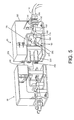
- a pair of insulated conductors 100, 110 are interconnected to a conductive housing 120 of the female adapter 60.
- Each of the insulated conductors 100, 110 are preferably triaxial conductors and rated for at least 1,500 volts (or co-axial conductors and rated for at least 3,000 volts). Depending on the particular configuration, co-axial and/or triaxial conductors may likewise be used having lower rating capabilities, and in particular low-noise low voltage cables.
- the shield conductor of each triaxial conductor 100, 110 is preferably interconnected to a conductive support 150.
- the conductors 100, 110 are preferably substantially straight between the outside of the enclosure and the conductive support 150, which reduces strain on the conductors 100, 110.
- the conductive support 150 is electrically connected with the conductive housing 120.
- the conductors 100, 110 are preferably supported by a pair of respective threaded rings 130, 140.
- the shield has a "ground” potential
- the shield conductors 130, 140 may be interconnected together by the conductive support 150 and/or the conductive housing 120.
- the conductive housing 120 preferably surrounds all, or substantially surrounds all, of the connectors enclosed therein. In this manner, the ground potential may be provided to the conductive housing 120 which provides, at least in part, a low noise interconnection environment for the signal connectors.
- the conductive support 150 and/or the conductive housing 120 are sufficiently spaced apart from the remaining guard and signal paths such that high power measurements, high voltage and/or high current, may be performed without arcing or other safety issues.
- the conductors 100, 110 extend further into the adapter 60 with the shield conductor 130, 140 (and exterior insulation, if any) being removed.
- the guard conductors 160, 170 of each of the triaxial conductors 100, 110 is preferably interconnected to a conductive support 180.
- the conductors 100, 110 are preferably substantially straight between the two aligned conductive supports 150, 180 which reduces strain on the conductors 100, 110.
- the conductive support 180 is electrically connected to a conductive inner housing 190.
- the inner housing 190 provides an inner enclosure around the signal conductor.
- the conductive support 180 and/or the conductive inner housing 190 are sufficiently spaced apart from the remaining signal paths and ground paths such that high power measurement, high voltage and/or high current, may be performed without arcing or other safety issues.
- the guard has a "guard" potential, so the guard conductors 160, 170 may be interconnected together by the conductive support 180 and/or the inner housing 190.
- the inner housing 190 preferably surrounds all, or substantially surrounds all, of the connectors enclosed therein. In this manner, the guard potential may be provided to the inner housing 190 which provides, at least in part, a low noise interconnection environment for the signal connectors.
- the conductors 100, 110 extend further into the adapter 60 with the guard conductors 170, 180 (and external insulation, if any) being removed.
- the remaining signal conductors 200, 210 are preferably each connected to a respective connector 220, 230.
- the signal conductors 200, 210 are preferably substantially straight between the conductive support 180 and the respective signal connectors 220, 230, which reduces strain on the conductors 100, 110.
- the signal connectors 220, 230 provide an interconnection between the female adapter 60 and the male adapter 50.
- the female adapter 60 includes a guard connector 240 that is electrically interconnected to the inner housing 190.
- the guard potential may be provided in a suitable manner for interconnecting with the male connector 50.
- the signal connectors 220, 230 are preferably arranged in a spaced apart arrangement where the space between the connectors is approximately at least the diameter of one of the signal connectors.
- the guard connector 240 is preferably in a spaced apart arrangement from the connectors 220, 230 where the space between the signal / guard connectors is approximately at least twice the diameter of one of the signal connectors. In general, preferably the spacing between the signal connectors is less than the spacing between the respective signal connectors and the guard connector. This spacing arrangement increases the signal integrity.
- the female adapter 60 includes a shield connector 260 that is electrically interconnected to the housing 120.
- the shield potential may be provided in a suitable manner for interconnecting with the male connector 50.
- the shield connector 260 is preferably arranged in a spaced apart arrangement from the guard connector 240 where the space between them is approximately at least the diameter of one of the signal connectors. This spacing arrangement increases the signal integrity.
- the adapters 50, 60 provide a low resistance connection and a low noise environment for signals combining high voltage and high current.
- the connection can conduct continuous direct current up to approximately 50 Amps (A) and one millisecond pulses at a 20Hz pulse rate of approximately 1000A with a resistance less than 1milliohm.
- typically tri-axial connectors are used and the signal conductors pass through the female adapter 60 while simultaneously maintaining a shielding environment and a guarded environment for signal integrity.
- typically a co-axial connector is used and the signal conductors similarly pass through the female adapter 60, in a relatively safe spaced apart arrangement, while simultaneously providing a grounded signal path through the "guard" connector.
- the shield connection may not be used, or otherwise the shield connection may be used while the guard connection is not used.
- Ultra low noise measurement using especially low-currents are typically performed with two conductive paths ("force” and "sense") either reaching the test site independently (“true Kelvin” connection) or joining together in the proximity of the test site (“quasi Kelvin” connection) to form a “signal path.”
- the force path whose test equipment terminus has a relatively low impedance, is provided with a particular current.
- the sense path whose test equipment terminus has a very high impedance, measures the voltage at the test site. As such, the current versus voltage characteristics of the test device can be obtained using the force and sense paths.
- This test configuration is desirable because although small variations in current are being measured, the amount of current directed to the test site might be large enough so that there is a significant voltage drop through the signal line leading to the test site.
- the distance from the test site to the point at which the signal path splits into force and sense path is a determinant of test quality, referred to in the low-current test industry as the degree to which the test configuration approaches the ideal "true kelvin" configuration in which the force and sense paths are connected by the conductive test site itself.
- the force and sense paths are referred to as the signal path(s).
- the female adapter 60 and the male adapter 50 are configured such that the connection maintains the ability to perform a "true” or "quasi" Kelvin connection, as desired.
- the male adapter 50 has a corresponding configuration as the female adapter 60, with the connectors being correspondingly modified.
- the male adapter 50 is typically secured to the probe station so that it is maintained in a secured position.
- the cables from the male adapter 50 are typically interconnected to suitable probes and/or the chuck in a desired configuration. In this manner, the male adapter 50 and associated cables do not need to be modified often, if ever. This reduces the time for probing by reducing the time required to set up a particular test for probing.
- male and/or female adapters may be provided.
- alternative male adapters 60 are provided so as to maintain compatibility with the exiting female adapter 50.
- the male adapter may include a single coaxial cable where the two signal paths are shorted together which increases the power canying capability of the adapter.
- the male adapter may include one or more co-axial cables where the shield is electrically connected to the guard which increases the guarding and/or shielding of the adapter.
- the coaxial connector may use the shield connection and the signal connection, omitting the guard connection.
- connectors that can withstand higher voltage and/or higher amperages of a coaxial or tri-axial test up to 10,000 volts or more and/or 50 amps or more (pulsed).
- a connector that is easily configurable among a variety of biasing conductions, such as (1) shorted, (2) open, (3) tri-axial, and (4) coaxial configuration for biasing the chuck without the need to modify the cabling between the connector and the probe station.
- biasing conductions such as (1) shorted, (2) open, (3) tri-axial, and (4) coaxial configuration for biasing the chuck without the need to modify the cabling between the connector and the probe station.
- the signal path from the chuck is preferably a tri-axial connection 300.
- the tri-axial connection 300 has a signal path (e.g., force or sense), a guard conductor, and a shield conductor. This provides flexibility in the test being performed.
- the shield conductor 310 is preferably grounded 320.
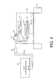
- the guard conductor 330 is connected to a switch 340 that selects between the ground connection 320 and a tri-axial connection 350.
- the tri-axial connection 350 is interconnected to a guard connection 360 of the output connector to the test instrumentation.
- the shield conductor 370 of the output connector is connected to the ground 320. In this manner, the guard potential / connection from the chuck may be selectively provided to the guard potential / connection of the output connector, or otherwise the guard potential / connection is grounded.
- the tri-axial connection 300 has a signal path 400 which is connected to a switch 410 that selects between a shorted connection 420 to ground 320 (preferably through a fuse), an open connection 430, and a connected connection 440.
- the shorted connection 420 facilitates measurements when one of the connections should be shorted, which is also useful for calibration.
- the open connection 430 facilitates measurements when one of the connections should be opened, which is also useful for calibration.
- the connected connection 440 is connected to a switch 450 that selects between a BNC connection 460 (or other connection, typically co-axial in nature) and a tri-axial connection 470. In this manner, the signal path from the chuck may be selectively shorted, opened, or passed through to a desired connector.
- the shield connection may likewise be provided from the chuck connector to the output connector, so that the shield potential may be a different ground, the chuck ground, or otherwise the test instrumentation ground, as desired.
- the adapter may include a data connection where remote commands may be used to select the position of the switches.
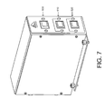
- a tri-position switch 510 may be included to control the position of the switch 410.
- a pair of dual position switches 500, 520 may be included to control the position of the switches 340, 450. This provides a convenient manner of controlling the switching positions.
- a suitable set of connectors may likewise be included together with a data port.
Landscapes
- Engineering & Computer Science (AREA)
- Physics & Mathematics (AREA)
- General Physics & Mathematics (AREA)
- Computer Hardware Design (AREA)
- Microelectronics & Electronic Packaging (AREA)
- General Engineering & Computer Science (AREA)
- Measuring Leads Or Probes (AREA)
- Testing Of Individual Semiconductor Devices (AREA)
- Testing Or Measuring Of Semiconductors Or The Like (AREA)
- Manufacturing Of Electrical Connectors (AREA)
- Connector Housings Or Holding Contact Members (AREA)
Claims (11)
- Rauscharmes Verbindungsstück für ein Kabelpaar, wobei jedes Kabel einen Innenleiter, einen koaxialen Mittelleiter, der den Innenleiter umgibt, aber konduktiv von diesem isoliert ist, und einen koaxialen Außenleiter, der den Mittelleiter und den Innenleiter umgibt, aber konduktiv von diesen isoliert ist, aufweist, wobei das Verbindungsstück Folgendes umfasst:(a) einen ersten Adapter, umfassend:(i) ein erstes inneres Verbindungsstück, das konduktiv mit dem Innenleiter eines ersten Kabels verbunden werden kann;(ii) ein erstes mittleres Verbindungsstück, das konduktiv mit dem Mittelleiter des ersten Kabels verbunden werden kann und konduktiv von dem ersten inneren Verbindungsstück isoliert ist;(iii) ein erstes äußeres Verbindungsstück, das konduktiv mit dem Außenleiter des ersten Kabels verbunden werden kann und konduktiv von dem ersten inneren Verbindungsstück und dem ersten mittleren Verbindungsstück isoliert ist;(iv) ein erstes inneres Gehäuse, das konduktiv mit dem ersten mittleren Verbindungsstück verbunden werden kann und konduktiv von dem ersten inneren Verbindungsstück und dem ersten äußeren Verbindungsstück isoliert ist; und(v) ein erstes äußeres Gehäuse, das konduktiv mit dem Außenleiter des ersten Kabels verbunden werden kann und konduktiv von dem ersten inneren Verbindungsstück und dem ersten mittleren Verbindungsstück isoliert ist; und(b) einen zweiten Adapter, der für Ineingriffnahme mit dem ersten Adapter angeordnet ist und Folgendes umfasst:(i) ein zweites inneres Verbindungsstück, das konduktiv mit dem Innenleiter eines zweiten Kabels verbunden werden kann und für passende Ineingriffnahme mit dem ersten inneren Verbindungsstück angeordnet ist, wenn der zweite Adapter mit dem ersten Adapter in Eingriff gelangt;(ii) ein zweites mittleres Verbindungsstück, das konduktiv mit dem Mittelleiter des zweiten Kabels verbunden werden kann und konduktiv von dem zweiten inneren Verbindungsstück isoliert ist, wobei das zweite mittlere Verbindungsstück für passende Ineingriffnahme mit dem ersten mittleren Verbindungsstück angeordnet ist, wenn der zweite Adapter mit dem ersten Adapter in Eingriff steht;(iii) ein zweites äußeres Verbindungsstück, das konduktiv mit dem Außenleiter des zweiten Kabels verbunden werden kann und konduktiv von dem zweiten inneren Verbindungsstück und dem zweiten mittleren Verbindungsstück isoliert ist, wobei das zweite äußere Verbindungsstück für passende Ineingriffnahme mit dem ersten äußeren Verbindungsstück angeordnet ist, wenn der zweite Adapter mit dem ersten Adapter in Eingriff steht;(iv) ein zweites inneres Gehäuse, das konduktiv mit dem zweiten mittleren Verbindungsstück verbunden ist und konduktiv von dem zweiten inneren Verbindungsstück und dem zweiten äußeren Verbindungsstück isoliert ist, wobei das zweite innere Gehäuse und das erste innere Gehäuse so angeordnet sind, dass sie das erste innere Verbindungsstück, das zweite innere Verbindungsstück, das erste mittlere Verbindungsstück und das zweite mittlere Verbindungsstück im Wesentlichen umschließen, wenn der erste Adapter mit dem zweiten Adapter in Eingriff steht; und(v) ein zweites äußeres Gehäuse, das konduktiv mit dem Außenleiter des zweiten Kabels verbunden werden kann und konduktiv von dem zweiten inneren Verbindungsstück und dem zweiten mittleren Verbindungsstück isoliert ist, wobei das zweite äußere Gehäuse und das erste äußere Gehäuse so angeordnet sind, dass sie das erste innere Gehäuse, das zweite innere Gehäuse, das erste äußere Verbindungsstück und das zweite äußere Verbindungsstück im Wesentlichen umschließen, wenn der erste Adapter mit dem zweiten Adapter in Eingriff steht.
- Rauscharmes Verbindungsstück nach Anspruch 1, wobei das erste innere Verbindungsstück und das erste äußere Verbindungsstück voneinander beabstandet sind und wobei ferner ein Abstand zwischen dem ersten inneren Verbindungsstück und dem ersten äußeren Verbindungsstück mindestens das Zweifache eines Durchmessers des ersten inneren Verbindungsstücks ist.
- Rauscharmes Verbindungsstück nach Anspruch 1, ferner umfassend eine leitfähige Verbindung zwischen dem ersten inneren Gehäuse und dem ersten äußeren Gehäuse.
- Rauscharmes Verbindungsstück nach Anspruch 1 zum Verbinden von vier Kabeln, wobei jedes Kabel einen Innenleiter, einen koaxialen Mittelleiter, der den Innenleiter umgibt, aber konduktiv davon isoliert ist, und einen koaxialen Außenleiter, der den Mittelleiter und den Innenleiter umgibt, aber konduktiv davon isoliert ist, aufweist,
wobei der erste Adapter zusätzlich ein drittes inneres Verbindungsstück umfasst, das konduktiv mit dem Innenleiter eines dritten Kabels verbunden werden kann;
und wobei das erste mittlere Verbindungsstück ebenfalls konduktiv mit dem Mittelleiter des dritten Kabels verbunden werden kann und konduktiv von dem dritten inneren Verbindungsstück isoliert ist;
und wobei das erste äußere Verbindungsstück ebenfalls konduktiv mit dem Außenleiter des dritten Kabels verbunden werden kann und konduktiv von dem dritten inneren Verbindungsstück und dem ersten mittleren Verbindungsstück isoliert ist;
und wobei das erste innere Gehäuse ebenfalls konduktiv von dem dritten inneren Verbindungsstück isoliert ist;
und wobei das erste äußere Gehäuse konduktiv mit dem Außenleiter des dritten Kabels verbunden werden kann und konduktiv von dem dritten inneren Verbindungsstück isoliert ist;
und wobei der zweite Adapter zusätzlich ein viertes inneres Verbindungsstück umfasst, das konduktiv mit dem Innenleiter eines vierten Kabels verbunden werden kann und für passende Ineingriffnahme mit dem dritten inneren Verbindungsstück angeordnet ist, wenn der zweite Adapter mit dem ersten Adapter in Eingriff steht;
und wobei das zweite mittlere Verbindungsstück ebenfalls konduktiv mit dem Mittelleiter des vierten Kabels verbunden werden kann und konduktiv von dem vierten inneren Verbindungsstück isoliert ist;
und wobei das zweite äußere Verbindungsstück ebenfalls konduktiv mit dem Außenleiter des vierten Kabels verbunden werden kann und konduktiv von dem vierten inneren Verbindungsstück isoliert ist;
und wobei das zweite innere Gehäuse konduktiv von dem vierten inneren Verbindungsstück isoliert ist und das zweite innere Gehäuse und das erste innere Gehäuse ebenfalls so angeordnet sind, dass sie das dritte und das vierte innere Verbindungsstück im Wesentlichen umschließen;
und wobei das zweite äußere Gehäuse konduktiv mit dem Außenleiter des vierten Kabels verbunden werden kann und konduktiv von dem vierten inneren Verbindungsstück isoliert ist. - Rauscharmes Verbindungsstück nach Anspruch 1 oder Anspruch 4, wobei das erste innere Verbindungsstück und das zweite innere Verbindungsstück miteinander verbunden werden können, um ein Signal zwischen einer Sondenstation und einem Instrument zu leiten.
- Rauscharmes Verbindungsstück nach Anspruch 1 oder Anspruch 4, wobei das erste mittlere Verbindungsstück und das zweite mittlere Verbindungsstück mit einem Schutzpotenzial verbunden werden können.
- Rauscharmes Verbindungsstück nach Anspruch 1 oder Anspruch 4, wobei das erste äußere Verbindungsstück und das zweite äußere Verbindungsstück mit einem Schirmpotenzial verbunden werden können.
- Rauscharmes Verbindungsstück nach Anspruch 1 oder Anspruch 4, wobei das erste mittlere Verbindungsstück und das erste äußere Verbindungsstück voneinander beabstandet sind und wobei ferner ein Abstand zwischen dem ersten mittleren Verbindungsstück und dem ersten äußeren Verbindungsstück mindestens gleich einem Durchmesser des ersten inneren Verbindungsstücks ist.
- Rauscharmes Verbindungsstück nach Anspruch 4, wobei das erste innere Verbindungsstück und das erste äußere Verbindungsstück voneinander beabstandet sind, wobei ein Abstand zwischen dem ersten inneren Verbindungsstück und dem ersten äußeren Verbindungsstück mindestens das Zweifache eines Durchmessers des ersten inneren Verbindungsstücks ist und wobei ferner ein Abstand zwischen dem dritten inneren Verbindungsstück und dem ersten äußeren Verbindungsstück mindestens das Zweifache des Durchmessers des ersten inneren Verbindungsstücks ist.
- Rauscharmes Verbindungsstück nach Anspruch 4, wobei das erste innere Verbindungsstück und das dritte innere Verbindungsstück voneinander beabstandet sind und wobei ferner ein Abstand zwischen dem ersten inneren Verbindungsstück und dem dritten inneren Verbindungsstück mindestens gleich einem Durchmesser des ersten inneren Verbindungsstücks ist.
- Rauscharmes Verbindungsstück nach Anspruch 4, wobei das erste mittlere Verbindungsstück, das erste innere Verbindungsstück und das dritte innere Verbindungsstück voneinander beabstandet sind und wobei ferner ein Abstand zwischen dem ersten mittleren Verbindungsstück und dem ersten inneren Verbindungsstück mindestens gleich einem Durchmesser des ersten inneren Verbindungsstücks ist und ein Abstand zwischen dem ersten mittleren Verbindungsstück und dem dritten inneren Verbindungsstück mindestens gleich dem Durchmesser des ersten inneren Verbindungsstücks ist.
Applications Claiming Priority (2)
| Application Number | Priority Date | Filing Date | Title |
|---|---|---|---|
| US30687810P | 2010-02-22 | 2010-02-22 | |
| PCT/US2011/025476 WO2011103461A1 (en) | 2010-02-22 | 2011-02-18 | Probe station with improved interconnection |
Publications (3)
| Publication Number | Publication Date |
|---|---|
| EP2539724A1 EP2539724A1 (de) | 2013-01-02 |
| EP2539724A4 EP2539724A4 (de) | 2013-11-27 |
| EP2539724B1 true EP2539724B1 (de) | 2015-01-28 |
Family
ID=44476891
Family Applications (1)
| Application Number | Title | Priority Date | Filing Date |
|---|---|---|---|
| EP11745352.2A Not-in-force EP2539724B1 (de) | 2010-02-22 | 2011-02-18 | Sondenstation mit verbesserter verbindung |
Country Status (5)
| Country | Link |
|---|---|
| US (1) | US8167648B2 (de) |
| EP (1) | EP2539724B1 (de) |
| JP (1) | JP5297562B2 (de) |
| KR (1) | KR101481876B1 (de) |
| WO (1) | WO2011103461A1 (de) |
Families Citing this family (2)
| Publication number | Priority date | Publication date | Assignee | Title |
|---|---|---|---|---|
| US11927605B2 (en) * | 2019-06-06 | 2024-03-12 | Keithley Instruments, Llc | Interconnect system with high current and low leakage capability |
| US11346883B2 (en) * | 2019-11-05 | 2022-05-31 | Formfactor, Inc. | Probe systems and methods for testing a device under test |
Family Cites Families (13)
| Publication number | Priority date | Publication date | Assignee | Title |
|---|---|---|---|---|
| US5181860A (en) * | 1990-03-28 | 1993-01-26 | Daiichi Denshi Kogyo Kabushiki Kaisha | Electrical connector with rotatable locking ring |
| JPH05217635A (ja) * | 1992-02-03 | 1993-08-27 | Fujitsu Ltd | シールド強化形同軸コネクタ |
| US6034533A (en) * | 1997-06-10 | 2000-03-07 | Tervo; Paul A. | Low-current pogo probe card |
| US6744268B2 (en) * | 1998-08-27 | 2004-06-01 | The Micromanipulator Company, Inc. | High resolution analytical probe station |
| US6124723A (en) * | 1998-08-31 | 2000-09-26 | Wentworth Laboratories, Inc. | Probe holder for low voltage, low current measurements in a water probe station |
| US6914423B2 (en) * | 2000-09-05 | 2005-07-05 | Cascade Microtech, Inc. | Probe station |
| US6847219B1 (en) * | 2002-11-08 | 2005-01-25 | Cascade Microtech, Inc. | Probe station with low noise characteristics |
| US7070448B2 (en) * | 2004-03-25 | 2006-07-04 | Adc Telecommunications, Inc. | Coaxial/triaxial adapter assembly including an adapter and interchangeable connector ends and method |
| JP2005321379A (ja) * | 2004-04-07 | 2005-11-17 | Agilent Technol Inc | 半導体特性測定装置の統合接続装置およびケーブルアセンブリ |
| US7740501B2 (en) * | 2007-06-06 | 2010-06-22 | Claudio R. Ballard | Hybrid cable for conveying data and power |
| US20090318020A1 (en) * | 2008-06-24 | 2009-12-24 | Tyco Electronics Corporation | Adapter for a coaxial cable connector |
| US8016615B2 (en) * | 2009-09-09 | 2011-09-13 | John Mezzalingua Associates, Inc. | Phone plug connector device |
| US7997929B2 (en) * | 2009-08-13 | 2011-08-16 | John Mezzalingua Associates, Inc. | Phone plug connector device |
-
2011
- 2011-02-18 US US13/030,961 patent/US8167648B2/en active Active
- 2011-02-18 EP EP11745352.2A patent/EP2539724B1/de not_active Not-in-force
- 2011-02-18 JP JP2012554061A patent/JP5297562B2/ja active Active
- 2011-02-18 KR KR1020127024802A patent/KR101481876B1/ko not_active Expired - Fee Related
- 2011-02-18 WO PCT/US2011/025476 patent/WO2011103461A1/en not_active Ceased
Also Published As
| Publication number | Publication date |
|---|---|
| EP2539724A4 (de) | 2013-11-27 |
| JP5297562B2 (ja) | 2013-09-25 |
| US8167648B2 (en) | 2012-05-01 |
| EP2539724A1 (de) | 2013-01-02 |
| JP2013520770A (ja) | 2013-06-06 |
| KR20130018705A (ko) | 2013-02-25 |
| US20110207370A1 (en) | 2011-08-25 |
| WO2011103461A1 (en) | 2011-08-25 |
| KR101481876B1 (ko) | 2015-01-12 |
Similar Documents
| Publication | Publication Date | Title |
|---|---|---|
| US7068060B2 (en) | Connection apparatus and cable assembly for semiconductor-device characteristic measurement apparatus | |
| JP5254919B2 (ja) | 高性能テスターインタフェースモジュール | |
| US20060066343A1 (en) | Semiconductor device characteristics measurement apparatus and connection apparatus | |
| WO2013066525A1 (en) | Connectors for invoking and supporting device testing | |
| JP2017173324A (ja) | フレキシブル抵抗性チップ・ケーブル・アセンブリ及びケーブル | |
| US10663530B2 (en) | Test switch assembly having an electronic circuit | |
| KR101853192B1 (ko) | 케이블 테스트 장치 | |
| JP6893069B2 (ja) | Rfアダプタ | |
| JP3336525B2 (ja) | 通信方法 | |
| US8167648B2 (en) | Low noise connector with cables having a center, middle and outer conductors | |
| KR101989232B1 (ko) | 테스트 회로기판 및 이를 구동하기 위한 방법 | |
| CN105510757B (zh) | 三轴dc-ac连接系统 | |
| CN103116045A (zh) | Dc-ac探针卡拓扑 | |
| US9316685B2 (en) | Probe card of low power loss | |
| US20250130259A1 (en) | Power probe fixtures and adapters | |
| KR102530370B1 (ko) | 브레이크 아웃 박스 | |
| US8593233B1 (en) | Coaxial cable multiplexor | |
| JP4742095B2 (ja) | 半導体素子のテストフィクスチャおよび試験用アセンブリのための電気コネクタ | |
| US20030062914A1 (en) | Surface mating compliant contact assembly with fixed signal path length | |
| JP4979062B2 (ja) | 信号伝達回路装置 | |
| CN224231808U (zh) | 转接治具和电压测试设备 | |
| KR20220059379A (ko) | 스위치를 포함하는 케이블 테스트 장치 | |
| KR102601061B1 (ko) | 브레이크 아웃 박스 | |
| CN107765113B (zh) | 一种对飞行器测试信号分路处理的方法 | |
| CN108508289B (zh) | 机器人电路分析器工具 |
Legal Events
| Date | Code | Title | Description |
|---|---|---|---|
| PUAI | Public reference made under article 153(3) epc to a published international application that has entered the european phase |
Free format text: ORIGINAL CODE: 0009012 |
|
| 17P | Request for examination filed |
Effective date: 20120910 |
|
| AK | Designated contracting states |
Kind code of ref document: A1 Designated state(s): AL AT BE BG CH CY CZ DE DK EE ES FI FR GB GR HR HU IE IS IT LI LT LU LV MC MK MT NL NO PL PT RO RS SE SI SK SM TR |
|
| DAX | Request for extension of the european patent (deleted) | ||
| REG | Reference to a national code |
Ref country code: DE Ref legal event code: R079 Ref document number: 602011013541 Country of ref document: DE Free format text: PREVIOUS MAIN CLASS: G01R0031200000 Ipc: H01R0013659700 |
|
| A4 | Supplementary search report drawn up and despatched |
Effective date: 20131024 |
|
| RIC1 | Information provided on ipc code assigned before grant |
Ipc: H01R 24/56 20110101ALI20131018BHEP Ipc: H01R 13/6597 20110101AFI20131018BHEP Ipc: G01R 31/28 20060101ALI20131018BHEP |
|
| GRAP | Despatch of communication of intention to grant a patent |
Free format text: ORIGINAL CODE: EPIDOSNIGR1 |
|
| 17Q | First examination report despatched |
Effective date: 20140813 |
|
| INTG | Intention to grant announced |
Effective date: 20140910 |
|
| GRAS | Grant fee paid |
Free format text: ORIGINAL CODE: EPIDOSNIGR3 |
|
| GRAA | (expected) grant |
Free format text: ORIGINAL CODE: 0009210 |
|
| AK | Designated contracting states |
Kind code of ref document: B1 Designated state(s): AL AT BE BG CH CY CZ DE DK EE ES FI FR GB GR HR HU IE IS IT LI LT LU LV MC MK MT NL NO PL PT RO RS SE SI SK SM TR |
|
| REG | Reference to a national code |
Ref country code: GB Ref legal event code: FG4D |
|
| REG | Reference to a national code |
Ref country code: CH Ref legal event code: EP |
|
| REG | Reference to a national code |
Ref country code: IE Ref legal event code: FG4D |
|
| REG | Reference to a national code |
Ref country code: DE Ref legal event code: R096 Ref document number: 602011013541 Country of ref document: DE Effective date: 20150312 |
|
| REG | Reference to a national code |
Ref country code: AT Ref legal event code: REF Ref document number: 708598 Country of ref document: AT Kind code of ref document: T Effective date: 20150315 |
|
| REG | Reference to a national code |
Ref country code: NL Ref legal event code: VDEP Effective date: 20150128 |
|
| REG | Reference to a national code |
Ref country code: LT Ref legal event code: MG4D |
|
| PG25 | Lapsed in a contracting state [announced via postgrant information from national office to epo] |
Ref country code: BE Free format text: LAPSE BECAUSE OF NON-PAYMENT OF DUE FEES Effective date: 20150228 |
|
| PG25 | Lapsed in a contracting state [announced via postgrant information from national office to epo] |
Ref country code: NO Free format text: LAPSE BECAUSE OF FAILURE TO SUBMIT A TRANSLATION OF THE DESCRIPTION OR TO PAY THE FEE WITHIN THE PRESCRIBED TIME-LIMIT Effective date: 20150428 Ref country code: BG Free format text: LAPSE BECAUSE OF FAILURE TO SUBMIT A TRANSLATION OF THE DESCRIPTION OR TO PAY THE FEE WITHIN THE PRESCRIBED TIME-LIMIT Effective date: 20150428 Ref country code: ES Free format text: LAPSE BECAUSE OF FAILURE TO SUBMIT A TRANSLATION OF THE DESCRIPTION OR TO PAY THE FEE WITHIN THE PRESCRIBED TIME-LIMIT Effective date: 20150128 Ref country code: HR Free format text: LAPSE BECAUSE OF FAILURE TO SUBMIT A TRANSLATION OF THE DESCRIPTION OR TO PAY THE FEE WITHIN THE PRESCRIBED TIME-LIMIT Effective date: 20150128 Ref country code: SE Free format text: LAPSE BECAUSE OF FAILURE TO SUBMIT A TRANSLATION OF THE DESCRIPTION OR TO PAY THE FEE WITHIN THE PRESCRIBED TIME-LIMIT Effective date: 20150128 Ref country code: FI Free format text: LAPSE BECAUSE OF FAILURE TO SUBMIT A TRANSLATION OF THE DESCRIPTION OR TO PAY THE FEE WITHIN THE PRESCRIBED TIME-LIMIT Effective date: 20150128 Ref country code: LT Free format text: LAPSE BECAUSE OF FAILURE TO SUBMIT A TRANSLATION OF THE DESCRIPTION OR TO PAY THE FEE WITHIN THE PRESCRIBED TIME-LIMIT Effective date: 20150128 |
|
| PG25 | Lapsed in a contracting state [announced via postgrant information from national office to epo] |
Ref country code: IS Free format text: LAPSE BECAUSE OF FAILURE TO SUBMIT A TRANSLATION OF THE DESCRIPTION OR TO PAY THE FEE WITHIN THE PRESCRIBED TIME-LIMIT Effective date: 20150528 Ref country code: NL Free format text: LAPSE BECAUSE OF FAILURE TO SUBMIT A TRANSLATION OF THE DESCRIPTION OR TO PAY THE FEE WITHIN THE PRESCRIBED TIME-LIMIT Effective date: 20150128 Ref country code: PL Free format text: LAPSE BECAUSE OF FAILURE TO SUBMIT A TRANSLATION OF THE DESCRIPTION OR TO PAY THE FEE WITHIN THE PRESCRIBED TIME-LIMIT Effective date: 20150128 Ref country code: LV Free format text: LAPSE BECAUSE OF FAILURE TO SUBMIT A TRANSLATION OF THE DESCRIPTION OR TO PAY THE FEE WITHIN THE PRESCRIBED TIME-LIMIT Effective date: 20150128 Ref country code: RS Free format text: LAPSE BECAUSE OF FAILURE TO SUBMIT A TRANSLATION OF THE DESCRIPTION OR TO PAY THE FEE WITHIN THE PRESCRIBED TIME-LIMIT Effective date: 20150128 Ref country code: GR Free format text: LAPSE BECAUSE OF FAILURE TO SUBMIT A TRANSLATION OF THE DESCRIPTION OR TO PAY THE FEE WITHIN THE PRESCRIBED TIME-LIMIT Effective date: 20150429 |
|
| REG | Reference to a national code |
Ref country code: CH Ref legal event code: PL |
|
| REG | Reference to a national code |
Ref country code: DE Ref legal event code: R097 Ref document number: 602011013541 Country of ref document: DE |
|
| PG25 | Lapsed in a contracting state [announced via postgrant information from national office to epo] |
Ref country code: RO Free format text: LAPSE BECAUSE OF FAILURE TO SUBMIT A TRANSLATION OF THE DESCRIPTION OR TO PAY THE FEE WITHIN THE PRESCRIBED TIME-LIMIT Effective date: 20150128 Ref country code: SK Free format text: LAPSE BECAUSE OF FAILURE TO SUBMIT A TRANSLATION OF THE DESCRIPTION OR TO PAY THE FEE WITHIN THE PRESCRIBED TIME-LIMIT Effective date: 20150128 Ref country code: EE Free format text: LAPSE BECAUSE OF FAILURE TO SUBMIT A TRANSLATION OF THE DESCRIPTION OR TO PAY THE FEE WITHIN THE PRESCRIBED TIME-LIMIT Effective date: 20150128 Ref country code: DK Free format text: LAPSE BECAUSE OF FAILURE TO SUBMIT A TRANSLATION OF THE DESCRIPTION OR TO PAY THE FEE WITHIN THE PRESCRIBED TIME-LIMIT Effective date: 20150128 Ref country code: CZ Free format text: LAPSE BECAUSE OF FAILURE TO SUBMIT A TRANSLATION OF THE DESCRIPTION OR TO PAY THE FEE WITHIN THE PRESCRIBED TIME-LIMIT Effective date: 20150128 Ref country code: MC Free format text: LAPSE BECAUSE OF FAILURE TO SUBMIT A TRANSLATION OF THE DESCRIPTION OR TO PAY THE FEE WITHIN THE PRESCRIBED TIME-LIMIT Effective date: 20150128 Ref country code: CH Free format text: LAPSE BECAUSE OF NON-PAYMENT OF DUE FEES Effective date: 20150228 Ref country code: LI Free format text: LAPSE BECAUSE OF NON-PAYMENT OF DUE FEES Effective date: 20150228 |
|
| REG | Reference to a national code |
Ref country code: IE Ref legal event code: MM4A |
|
| PLBE | No opposition filed within time limit |
Free format text: ORIGINAL CODE: 0009261 |
|
| STAA | Information on the status of an ep patent application or granted ep patent |
Free format text: STATUS: NO OPPOSITION FILED WITHIN TIME LIMIT |
|
| GBPC | Gb: european patent ceased through non-payment of renewal fee |
Effective date: 20150428 |
|
| 26N | No opposition filed |
Effective date: 20151029 |
|
| PG25 | Lapsed in a contracting state [announced via postgrant information from national office to epo] |
Ref country code: GB Free format text: LAPSE BECAUSE OF NON-PAYMENT OF DUE FEES Effective date: 20150428 Ref country code: IE Free format text: LAPSE BECAUSE OF NON-PAYMENT OF DUE FEES Effective date: 20150218 |
|
| REG | Reference to a national code |
Ref country code: FR Ref legal event code: PLFP Year of fee payment: 6 |
|
| PG25 | Lapsed in a contracting state [announced via postgrant information from national office to epo] |
Ref country code: SI Free format text: LAPSE BECAUSE OF FAILURE TO SUBMIT A TRANSLATION OF THE DESCRIPTION OR TO PAY THE FEE WITHIN THE PRESCRIBED TIME-LIMIT Effective date: 20150128 |
|
| PG25 | Lapsed in a contracting state [announced via postgrant information from national office to epo] |
Ref country code: BE Free format text: LAPSE BECAUSE OF FAILURE TO SUBMIT A TRANSLATION OF THE DESCRIPTION OR TO PAY THE FEE WITHIN THE PRESCRIBED TIME-LIMIT Effective date: 20150128 |
|
| REG | Reference to a national code |
Ref country code: AT Ref legal event code: UEP Ref document number: 708598 Country of ref document: AT Kind code of ref document: T Effective date: 20150128 |
|
| PG25 | Lapsed in a contracting state [announced via postgrant information from national office to epo] |
Ref country code: MT Free format text: LAPSE BECAUSE OF FAILURE TO SUBMIT A TRANSLATION OF THE DESCRIPTION OR TO PAY THE FEE WITHIN THE PRESCRIBED TIME-LIMIT Effective date: 20150128 |
|
| REG | Reference to a national code |
Ref country code: FR Ref legal event code: PLFP Year of fee payment: 7 |
|
| PG25 | Lapsed in a contracting state [announced via postgrant information from national office to epo] |
Ref country code: HU Free format text: LAPSE BECAUSE OF FAILURE TO SUBMIT A TRANSLATION OF THE DESCRIPTION OR TO PAY THE FEE WITHIN THE PRESCRIBED TIME-LIMIT; INVALID AB INITIO Effective date: 20110218 Ref country code: SM Free format text: LAPSE BECAUSE OF FAILURE TO SUBMIT A TRANSLATION OF THE DESCRIPTION OR TO PAY THE FEE WITHIN THE PRESCRIBED TIME-LIMIT Effective date: 20150128 |
|
| PG25 | Lapsed in a contracting state [announced via postgrant information from national office to epo] |
Ref country code: CY Free format text: LAPSE BECAUSE OF FAILURE TO SUBMIT A TRANSLATION OF THE DESCRIPTION OR TO PAY THE FEE WITHIN THE PRESCRIBED TIME-LIMIT Effective date: 20150128 |
|
| PG25 | Lapsed in a contracting state [announced via postgrant information from national office to epo] |
Ref country code: PT Free format text: LAPSE BECAUSE OF FAILURE TO SUBMIT A TRANSLATION OF THE DESCRIPTION OR TO PAY THE FEE WITHIN THE PRESCRIBED TIME-LIMIT Effective date: 20150528 |
|
| PG25 | Lapsed in a contracting state [announced via postgrant information from national office to epo] |
Ref country code: TR Free format text: LAPSE BECAUSE OF FAILURE TO SUBMIT A TRANSLATION OF THE DESCRIPTION OR TO PAY THE FEE WITHIN THE PRESCRIBED TIME-LIMIT Effective date: 20150128 |
|
| PG25 | Lapsed in a contracting state [announced via postgrant information from national office to epo] |
Ref country code: LU Free format text: LAPSE BECAUSE OF NON-PAYMENT OF DUE FEES Effective date: 20150218 |
|
| REG | Reference to a national code |
Ref country code: FR Ref legal event code: PLFP Year of fee payment: 8 |
|
| PG25 | Lapsed in a contracting state [announced via postgrant information from national office to epo] |
Ref country code: MK Free format text: LAPSE BECAUSE OF FAILURE TO SUBMIT A TRANSLATION OF THE DESCRIPTION OR TO PAY THE FEE WITHIN THE PRESCRIBED TIME-LIMIT Effective date: 20150128 |
|
| PG25 | Lapsed in a contracting state [announced via postgrant information from national office to epo] |
Ref country code: AL Free format text: LAPSE BECAUSE OF FAILURE TO SUBMIT A TRANSLATION OF THE DESCRIPTION OR TO PAY THE FEE WITHIN THE PRESCRIBED TIME-LIMIT Effective date: 20150128 |
|
| REG | Reference to a national code |
Ref country code: DE Ref legal event code: R081 Ref document number: 602011013541 Country of ref document: DE Owner name: FORMFACTOR, INC., LIVERMORE, US Free format text: FORMER OWNER: CASCADE MICROTECH, INC., BEAVERTON, OREG., US |
|
| P01 | Opt-out of the competence of the unified patent court (upc) registered |
Effective date: 20230315 |
|
| PGFP | Annual fee paid to national office [announced via postgrant information from national office to epo] |
Ref country code: DE Payment date: 20230406 Year of fee payment: 13 |
|
| PGFP | Annual fee paid to national office [announced via postgrant information from national office to epo] |
Ref country code: AT Payment date: 20240213 Year of fee payment: 14 |
|
| PGFP | Annual fee paid to national office [announced via postgrant information from national office to epo] |
Ref country code: IT Payment date: 20240207 Year of fee payment: 14 Ref country code: FR Payment date: 20240228 Year of fee payment: 14 |
|
| REG | Reference to a national code |
Ref country code: DE Ref legal event code: R119 Ref document number: 602011013541 Country of ref document: DE |
|
| PG25 | Lapsed in a contracting state [announced via postgrant information from national office to epo] |
Ref country code: DE Free format text: LAPSE BECAUSE OF NON-PAYMENT OF DUE FEES Effective date: 20240903 |
|
| PG25 | Lapsed in a contracting state [announced via postgrant information from national office to epo] |
Ref country code: DE Free format text: LAPSE BECAUSE OF NON-PAYMENT OF DUE FEES Effective date: 20240903 |
|
| REG | Reference to a national code |
Ref country code: AT Ref legal event code: MM01 Ref document number: 708598 Country of ref document: AT Kind code of ref document: T Effective date: 20250218 |
|
| PG25 | Lapsed in a contracting state [announced via postgrant information from national office to epo] |
Ref country code: AT Free format text: LAPSE BECAUSE OF NON-PAYMENT OF DUE FEES Effective date: 20250218 |
|
| PG25 | Lapsed in a contracting state [announced via postgrant information from national office to epo] |
Ref country code: FR Free format text: LAPSE BECAUSE OF NON-PAYMENT OF DUE FEES Effective date: 20250228 Ref country code: IT Free format text: LAPSE BECAUSE OF NON-PAYMENT OF DUE FEES Effective date: 20250218 |