EP2534274B1 - Verfahren und vorrichtung zur herstellung von kraftfahrzeug-fahrwerkteilen - Google Patents
Verfahren und vorrichtung zur herstellung von kraftfahrzeug-fahrwerkteilen Download PDFInfo
- Publication number
- EP2534274B1 EP2534274B1 EP11701025.6A EP11701025A EP2534274B1 EP 2534274 B1 EP2534274 B1 EP 2534274B1 EP 11701025 A EP11701025 A EP 11701025A EP 2534274 B1 EP2534274 B1 EP 2534274B1
- Authority
- EP
- European Patent Office
- Prior art keywords
- mould
- cooling
- segments
- melt
- permanent
- Prior art date
- Legal status (The legal status is an assumption and is not a legal conclusion. Google has not performed a legal analysis and makes no representation as to the accuracy of the status listed.)
- Active
Links
- 238000000034 method Methods 0.000 title claims description 11
- 238000001816 cooling Methods 0.000 claims description 54
- 238000005266 casting Methods 0.000 claims description 18
- 229910045601 alloy Inorganic materials 0.000 claims description 14
- 239000000956 alloy Substances 0.000 claims description 14
- 230000005496 eutectics Effects 0.000 claims description 14
- 239000000155 melt Substances 0.000 claims description 14
- 238000007711 solidification Methods 0.000 claims description 14
- 230000008023 solidification Effects 0.000 claims description 14
- 239000013078 crystal Substances 0.000 claims description 12
- 238000010438 heat treatment Methods 0.000 claims description 8
- 229910000789 Aluminium-silicon alloy Inorganic materials 0.000 claims description 7
- 238000013022 venting Methods 0.000 claims description 7
- 238000004519 manufacturing process Methods 0.000 claims description 6
- 229910052782 aluminium Inorganic materials 0.000 claims description 5
- 230000005484 gravity Effects 0.000 claims description 5
- 229910052719 titanium Inorganic materials 0.000 claims description 5
- XLYOFNOQVPJJNP-UHFFFAOYSA-N water Substances O XLYOFNOQVPJJNP-UHFFFAOYSA-N 0.000 claims description 5
- 229910000831 Steel Inorganic materials 0.000 claims description 4
- 230000001427 coherent effect Effects 0.000 claims description 4
- 239000007789 gas Substances 0.000 claims description 4
- 239000010959 steel Substances 0.000 claims description 4
- 229910052796 boron Inorganic materials 0.000 claims description 3
- 229910052802 copper Inorganic materials 0.000 claims description 3
- 238000009826 distribution Methods 0.000 claims description 3
- 229910052749 magnesium Inorganic materials 0.000 claims description 3
- 230000008646 thermal stress Effects 0.000 claims description 3
- 229910000838 Al alloy Inorganic materials 0.000 claims description 2
- 238000007872 degassing Methods 0.000 claims description 2
- 239000012535 impurity Substances 0.000 claims description 2
- 229910052742 iron Inorganic materials 0.000 claims description 2
- MOWMLACGTDMJRV-UHFFFAOYSA-N nickel tungsten Chemical compound [Ni].[W] MOWMLACGTDMJRV-UHFFFAOYSA-N 0.000 claims description 2
- 238000001556 precipitation Methods 0.000 claims description 2
- 229910052725 zinc Inorganic materials 0.000 claims description 2
- 230000035882 stress Effects 0.000 claims 6
- 229910016459 AlB2 Inorganic materials 0.000 claims 1
- 229910017708 MgZn2 Inorganic materials 0.000 claims 1
- 235000011837 pasties Nutrition 0.000 claims 1
- 239000010936 titanium Substances 0.000 description 6
- PXHVJJICTQNCMI-UHFFFAOYSA-N Nickel Chemical compound [Ni] PXHVJJICTQNCMI-UHFFFAOYSA-N 0.000 description 4
- 230000000694 effects Effects 0.000 description 4
- 239000011777 magnesium Substances 0.000 description 4
- 239000002826 coolant Substances 0.000 description 3
- 238000013461 design Methods 0.000 description 3
- 229910003407 AlSi10Mg Inorganic materials 0.000 description 2
- IJGRMHOSHXDMSA-UHFFFAOYSA-N Atomic nitrogen Chemical compound N#N IJGRMHOSHXDMSA-UHFFFAOYSA-N 0.000 description 2
- FYYHWMGAXLPEAU-UHFFFAOYSA-N Magnesium Chemical compound [Mg] FYYHWMGAXLPEAU-UHFFFAOYSA-N 0.000 description 2
- 229910017706 MgZn Inorganic materials 0.000 description 2
- RTAQQCXQSZGOHL-UHFFFAOYSA-N Titanium Chemical compound [Ti] RTAQQCXQSZGOHL-UHFFFAOYSA-N 0.000 description 2
- 238000000137 annealing Methods 0.000 description 2
- 238000010276 construction Methods 0.000 description 2
- 239000010949 copper Substances 0.000 description 2
- 230000007797 corrosion Effects 0.000 description 2
- 238000005260 corrosion Methods 0.000 description 2
- 239000000203 mixture Substances 0.000 description 2
- 229910052759 nickel Inorganic materials 0.000 description 2
- 238000007670 refining Methods 0.000 description 2
- 230000000630 rising effect Effects 0.000 description 2
- 229920001187 thermosetting polymer Polymers 0.000 description 2
- ZOXJGFHDIHLPTG-UHFFFAOYSA-N Boron Chemical compound [B] ZOXJGFHDIHLPTG-UHFFFAOYSA-N 0.000 description 1
- RYGMFSIKBFXOCR-UHFFFAOYSA-N Copper Chemical compound [Cu] RYGMFSIKBFXOCR-UHFFFAOYSA-N 0.000 description 1
- 241001076195 Lampsilis ovata Species 0.000 description 1
- 230000032683 aging Effects 0.000 description 1
- XAGFODPZIPBFFR-UHFFFAOYSA-N aluminium Chemical compound [Al] XAGFODPZIPBFFR-UHFFFAOYSA-N 0.000 description 1
- 230000015572 biosynthetic process Effects 0.000 description 1
- 238000012937 correction Methods 0.000 description 1
- 238000011161 development Methods 0.000 description 1
- 230000018109 developmental process Effects 0.000 description 1
- 238000007667 floating Methods 0.000 description 1
- 239000001257 hydrogen Substances 0.000 description 1
- 229910052739 hydrogen Inorganic materials 0.000 description 1
- 239000011261 inert gas Substances 0.000 description 1
- 238000011031 large-scale manufacturing process Methods 0.000 description 1
- 229910052751 metal Inorganic materials 0.000 description 1
- 239000002184 metal Substances 0.000 description 1
- 238000012544 monitoring process Methods 0.000 description 1
- 229910052757 nitrogen Inorganic materials 0.000 description 1
- 239000002244 precipitate Substances 0.000 description 1
- 238000004886 process control Methods 0.000 description 1
- 238000009423 ventilation Methods 0.000 description 1
Images







Classifications
-
- C—CHEMISTRY; METALLURGY
- C22—METALLURGY; FERROUS OR NON-FERROUS ALLOYS; TREATMENT OF ALLOYS OR NON-FERROUS METALS
- C22F—CHANGING THE PHYSICAL STRUCTURE OF NON-FERROUS METALS AND NON-FERROUS ALLOYS
- C22F1/00—Changing the physical structure of non-ferrous metals or alloys by heat treatment or by hot or cold working
- C22F1/04—Changing the physical structure of non-ferrous metals or alloys by heat treatment or by hot or cold working of aluminium or alloys based thereon
- C22F1/053—Changing the physical structure of non-ferrous metals or alloys by heat treatment or by hot or cold working of aluminium or alloys based thereon of alloys with zinc as the next major constituent
-
- B—PERFORMING OPERATIONS; TRANSPORTING
- B22—CASTING; POWDER METALLURGY
- B22C—FOUNDRY MOULDING
- B22C9/00—Moulds or cores; Moulding processes
- B22C9/06—Permanent moulds for shaped castings
-
- B—PERFORMING OPERATIONS; TRANSPORTING
- B22—CASTING; POWDER METALLURGY
- B22D—CASTING OF METALS; CASTING OF OTHER SUBSTANCES BY THE SAME PROCESSES OR DEVICES
- B22D15/00—Casting using a mould or core of which a part significant to the process is of high thermal conductivity, e.g. chill casting; Moulds or accessories specially adapted therefor
-
- B—PERFORMING OPERATIONS; TRANSPORTING
- B22—CASTING; POWDER METALLURGY
- B22D—CASTING OF METALS; CASTING OF OTHER SUBSTANCES BY THE SAME PROCESSES OR DEVICES
- B22D21/00—Casting non-ferrous metals or metallic compounds so far as their metallurgical properties are of importance for the casting procedure; Selection of compositions therefor
- B22D21/002—Castings of light metals
- B22D21/007—Castings of light metals with low melting point, e.g. Al 659 degrees C, Mg 650 degrees C
-
- B—PERFORMING OPERATIONS; TRANSPORTING
- B22—CASTING; POWDER METALLURGY
- B22D—CASTING OF METALS; CASTING OF OTHER SUBSTANCES BY THE SAME PROCESSES OR DEVICES
- B22D25/00—Special casting characterised by the nature of the product
- B22D25/02—Special casting characterised by the nature of the product by its peculiarity of shape; of works of art
-
- B—PERFORMING OPERATIONS; TRANSPORTING
- B22—CASTING; POWDER METALLURGY
- B22D—CASTING OF METALS; CASTING OF OTHER SUBSTANCES BY THE SAME PROCESSES OR DEVICES
- B22D25/00—Special casting characterised by the nature of the product
- B22D25/06—Special casting characterised by the nature of the product by its physical properties
-
- B—PERFORMING OPERATIONS; TRANSPORTING
- B22—CASTING; POWDER METALLURGY
- B22D—CASTING OF METALS; CASTING OF OTHER SUBSTANCES BY THE SAME PROCESSES OR DEVICES
- B22D27/00—Treating the metal in the mould while it is molten or ductile ; Pressure or vacuum casting
- B22D27/04—Influencing the temperature of the metal, e.g. by heating or cooling the mould
-
- B—PERFORMING OPERATIONS; TRANSPORTING
- B22—CASTING; POWDER METALLURGY
- B22D—CASTING OF METALS; CASTING OF OTHER SUBSTANCES BY THE SAME PROCESSES OR DEVICES
- B22D29/00—Removing castings from moulds, not restricted to casting processes covered by a single main group; Removing cores; Handling ingots
-
- B—PERFORMING OPERATIONS; TRANSPORTING
- B62—LAND VEHICLES FOR TRAVELLING OTHERWISE THAN ON RAILS
- B62D—MOTOR VEHICLES; TRAILERS
- B62D29/00—Superstructures, understructures, or sub-units thereof, characterised by the material thereof
- B62D29/008—Superstructures, understructures, or sub-units thereof, characterised by the material thereof predominantly of light alloys, e.g. extruded
-
- C—CHEMISTRY; METALLURGY
- C22—METALLURGY; FERROUS OR NON-FERROUS ALLOYS; TREATMENT OF ALLOYS OR NON-FERROUS METALS
- C22C—ALLOYS
- C22C21/00—Alloys based on aluminium
- C22C21/02—Alloys based on aluminium with silicon as the next major constituent
-
- C—CHEMISTRY; METALLURGY
- C22—METALLURGY; FERROUS OR NON-FERROUS ALLOYS; TREATMENT OF ALLOYS OR NON-FERROUS METALS
- C22C—ALLOYS
- C22C21/00—Alloys based on aluminium
- C22C21/02—Alloys based on aluminium with silicon as the next major constituent
- C22C21/04—Modified aluminium-silicon alloys
-
- C—CHEMISTRY; METALLURGY
- C22—METALLURGY; FERROUS OR NON-FERROUS ALLOYS; TREATMENT OF ALLOYS OR NON-FERROUS METALS
- C22C—ALLOYS
- C22C21/00—Alloys based on aluminium
- C22C21/10—Alloys based on aluminium with zinc as the next major constituent
-
- C—CHEMISTRY; METALLURGY
- C22—METALLURGY; FERROUS OR NON-FERROUS ALLOYS; TREATMENT OF ALLOYS OR NON-FERROUS METALS
- C22F—CHANGING THE PHYSICAL STRUCTURE OF NON-FERROUS METALS AND NON-FERROUS ALLOYS
- C22F1/00—Changing the physical structure of non-ferrous metals or alloys by heat treatment or by hot or cold working
- C22F1/04—Changing the physical structure of non-ferrous metals or alloys by heat treatment or by hot or cold working of aluminium or alloys based thereon
- C22F1/043—Changing the physical structure of non-ferrous metals or alloys by heat treatment or by hot or cold working of aluminium or alloys based thereon of alloys with silicon as the next major constituent
Definitions
- the invention relates to a method and an apparatus for the production of claiming on train, pressure and torsion automotive chassis parts with adjustable over the respective cross section mechanical strength, high ductility and temperature stability, from an AlSiZnMg alloy by chill casting.
- thermosetting alloys include, for example, G-AlSi12, G-AlSi10Mg, G-AlSi5Mg, G-Al3Si and copper-containing alloys which may additionally contain titanium, magnesium, nickel, or nickel and magnesium.
- the heat treatment depends on the respective alloy.
- the G-AlSi10Mg is solution-annealed at 520 to 530 ° C and quenched after a solution annealing time of 3 to 5 hours in water of 20 ° C. Hot aging takes place at temperatures between 160 and 165 ° C for 8 to 10 hours.
- Detailed information on the heat treatment of castings can be found in chapter 7.8 on pages 429 ff. Of the aluminum pocket book, 14th edition, for the respective alloys.
- GB 2229407 A describes a method for producing a vehicle frame in which a hollow core similar to the frame body is introduced into a mold, the core interior is sucked off and molten metal is introduced into a cavity between the core and casting surface of the mold.
- the object of the present invention is to propose a simple and cost-effective method as well as a pouring device which is suitable for carrying out operations and which makes it possible to use heavy-duty chassis parts with high mechanical strength values, high ductility and temperature stability and a low resistance AlSiZnMg alloy Porosity produce.
- the present method of making train-compression-and-torsion automotive chassis parts relates to affecting the mechanical strength, ductility, and temperature stability of a casting made from AlSiZnMg alloy.
- an aluminum alloy is used (in% by weight) Si 5 -11% Zn 4 - 9% mg 0.2 - 1.0% Sr 60 - 500 ppm and optionally at least one of the following elements Not a word 0.01 - 0.15% B 0.001-0.010% and maximum Zr 0.15% Ti 0.15% Fe 0.30% Cu 0.10% as well as other impurities individually up to 0.07% total up to 0.15% potted in the apparatus described below, wherein the individual mold segments of this device are cooled or heated in a punctiform to planar zone and thereby an interdendritic, eutectic mixed crystal structure is generated, consisting of Al mixed crystals and AlSi eutectic with coherent phases, formed by Precipitates of MgZn 2 and / or Mg 3 Z
- the mass ratio chill / chassis parts is equal to 0.9 - 1.2 and the eutectic melt is at a cooling rate of 0.01 to 10 ° C / s to obtain a mushy solidification with interdendritically distributed in the AlSi eutectic intermetallic phases in the mold shell cooled or heated intermittently, with the AlSiZnMg mixed crystal structure in each cross section the chassis part is formed homogeneously and identically.
- a density index of less than 10% can advantageously be B and / or Ti in the form of AlB 2, Al 3 Ti and AlTiC added and through a melt treatment (degassing) can be adjusted.
- the melt from the bottom rising (low pressure mold) or from above falling (gravity mold) is filled into the cup-shaped mold, wherein the mold wall during the filling phase has a temperature of 350 to 410 ° C and the melt selectively and intermittently with a cooling rate from 5 to 10 ° c / s on the tensile / compressive loaded sections until complete solidification, while cooling the ductile portions of the undercarriage at a cooling rate of 0.1 to 4 C / s.
- the inventive device for producing heavy-duty chassis parts from an AlSiZnMg alloy consists of a steel base frame 1, one or more mold segments 2, 3, an ejector system and the casting system, also a temperature control for the mold segments in conjunction with a water or air cooling and heating , Mold segments 2, 3 of Kokillenschalen with thin and thick-walled areas which are floatingly mounted on the base frame 1, wherein the thick-walled areas are formed as a support for the mold segments on the base frame, wherein in the thin-walled areas clamping bolt for selective clamping of the mold segments the base frame are arranged.
- the local temperature distribution can be detected by thermocouples and the respective thermal stress is compensated in the mold segments via the clamping bolt.
- a development of the device according to the invention is that the supports in the edge regions of the mold segments (2, 3) are arranged and each provided with a centering and a sliding surface, which corresponds to a correspondingly shaped counter surface on the steel frame (1).
- ejectors are arranged in addition to the casting removal for venting and, if necessary, for cooling the mold cavity.
- the mold can be vented through slot nozzles and vent inserts 13-16, preferably in the range of core brands or core inserts or inserts suction of the core gases via appropriate connections.
- the punctiform to planar zones are provided with special cooling devices such as trickle cooling or plate cooling, wherein the punctiform surfaces - based on the diameter - in the range of 10 to 40 mm, preferably 15 - 25 mm and the area zones in the range of 1000 - 50000 mm 2 are formed.
- special cooling devices such as trickle cooling or plate cooling
- FIG. 1 shows the basic structure of a segmented mold for the production of claim on train pressure and torsion automotive chassis parts without cooling or heating device.
- the segmented shell-shaped contour of a chassis part adapted mold consists of a base frame 1, mold segments 2, 3 and supports 20, 30 for supporting the mold segments relative to the base plate.
- clamping bolts 12.1 and 12.2 are arranged, which connect the mold segments 2, 3 with the base plate 1.
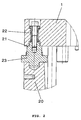
- FIG. 1 have the mold segments 2, 3 thin and thick-walled areas, the thick-walled areas in the example according to FIG. 1 as supports 20, 30 are formed. A more detailed description of this support area is the partial cross section according to FIG. 2 refer to.
- the upper part of the support 20 is formed by a sliding surface 21 which is arranged on a slider 23 which is non-positively connected to the mold segment.
- a respective guide pin 22 is connected to the slider 23.
- the structural design of the mold segments described above is required so that they can be stored floating on the base frame 1.
- the mold segments are designed as a so-called Kokillenschale, wherein the surface of the casting is thickened contour following the back.
- the wall thicknesses are in the range of 28 - 30 mm in the thin areas, so that here the individual segments of the mold can be cooled or heated specifically to the desired interdendritic, eutectic To be able to produce mixed-crystal structure consisting of Al mixed crystals and AlSi eutectic with coherent phases.
- the wall thicknesses of the segmented mold are reduced by 10 to 20 mm.
- the segments can be cooled or heated in a punctiform to planar zone.
- FIG. 3 an example of a point cooling by a trickle cooling 8 and given for a flat design cooling by cooling air duct 9.
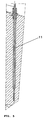
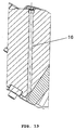
- the in FIG. 4 shown cooling device can be used in the form of a cooling plate 10.
- the local temperature distribution in the mold segments can be determined by means of temperature sensor 11, which are preferably connected to a computer (not shown), which monitors compliance with the predetermined cooling or heating phases via an integrated process monitoring and performs appropriate corrections in deviation from the desired values
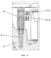
- FIG. 6 shows a further partial cross section through the device according to the invention in the area of trickle cooling 8.
- a cooling tube 8.1 is introduced into the region to be cooled of the mold segment 2 and the cooling medium is introduced via connection 8.2.
- the cooling effect can be controlled, for example, via the amount and the cooling time of the coolant.
- the inflow of the coolant by means of valve or the outflow can be influenced by throttle.
- the aim of this measure is to specifically target the mechanical characteristics required for the respective chassis parts to influence by controlling the solidification process.
- FIG. 7 and 8th Different variants of compressed air pipes can be used. So is in FIG. 7 a compressed air pipe 6.1 shown with many air outlet openings 6.2, which are directed against the mold wall of the mold segments 2. According to FIG. 8 It is also possible to connect a plurality of compressed air end pipes arranged in parallel with a central pipe 6.4. This increases the effective cooling surface, according to FIG. 8 consists of a thickened end of the mold segment 3.
- an interdendritic, eutectic mixed crystal structure consisting of Al mixed crystals and AlSi eutectic with coherent phases, formed by precipitations of MgZn 2 and / or Mg 3 Za 3 Al 2 .
- the air cooling according to FIG. 9 is used as pool cooling.
- a curved cooling tube can be placed around the pouring basin, so that the cooling of the residual melt, with the aim of controlling the cycle time, can be specifically influenced in the gate.
- thermocouples are used in a process control as a controlled variable for optimum solidification. After Patterson and Engler there are five different solidification types, depending on the alloy composition and cooling conditions form different microstructures of stiff-rough walled to dendritic cross-linked.
- the best mechanical strength values are achieved with a mush-like solidification of the melt with interdendritically distributed in the AlSi eutectic intermetallic phases, wherein the AlSiZnMg mixed crystal structure could be formed homogeneously and identically in each cross section of the chassis part according to the predetermined cooling conditions.
- a mold vent in particular for extracting the core gases, is arranged on the core walls.
- This consists of a vent insert 13, which is connected to a vent tube 17, which in turn is arranged in a core set 18.
- the effect of the suction can be additionally reinforced and accelerated by vacuum or Venturi nozzles.
- FIGS. 11-14 Mold vents by using air straps 13, by rib venting with slotted nozzles 14, 15 or by contour venting with slot 16 nozzles before.
- a density index of less than 10% can be set.
- the mold wall during the filling phase has a temperature of 350 to 410 ° C and the melt selectively and intermittently at a cooling rate of 5 to 10 ° C / s at the train-pressure loaded cross-sections until complete solidification is quenched, while the ductile portions of the chassis part are cooled at a cooling rate of 0.1 to 4 ° C / s.
- the flow aids and corrugations are made with ball cutters of diameter R1 and R0.5.
- the casting is removed from the mold and cold cured.
- the ejection of the casting is carried out by means of ejectors 5, which in FIG. 18 are shown with wear sleeve.
- the ejectors 5 are simultaneously used as ventilation via venting channel 19 and for partial cooling of the mold.
- the ejectors 5 are arranged in specially functionally thickened regions of the mold shell 2 for effective mold cooling (see FIG. 19 ).
- the density index less than 10% was set by treating the melt with inert gases or forming gases (nitrogen / argon-hydrogen mixtures).
- the parts were lunkerarm, the strength values were identical at all corners and cross-sectional areas of a chassis part.
- the surface quality was excellent, since only a small porosity occurred.
Landscapes
- Engineering & Computer Science (AREA)
- Chemical & Material Sciences (AREA)
- Mechanical Engineering (AREA)
- Materials Engineering (AREA)
- Metallurgy (AREA)
- Organic Chemistry (AREA)
- Crystallography & Structural Chemistry (AREA)
- Physics & Mathematics (AREA)
- Thermal Sciences (AREA)
- Structural Engineering (AREA)
- Combustion & Propulsion (AREA)
- Transportation (AREA)
- Architecture (AREA)
- Molds, Cores, And Manufacturing Methods Thereof (AREA)
- Body Structure For Vehicles (AREA)
- Moulds For Moulding Plastics Or The Like (AREA)
Description
- Die Erfindung betrifft ein Verfahren und eine Vorrichtung zur Herstellung von auf Zug, Druck und Torsion beanspruchbaren Kfz-Fahrwerksteilen mit über den jeweiligen Querschnitt einstellbarer mechanischer Festigkeit, einer hohen Duktilität und Temperaturstabilität, aus einer AlSiZnMg-Legierung durch Kokillenguss.
- Es ist bekannt, hochbeanspruchte Fahrwerksteile aus warmaushärtenden Legierungen durch Schwerkraft- oder Niederdruckguss herzustellen. Zu den warmaushärtenden Legierungen zählen beispielsweise G-AlSi12, G-AlSi10Mg, G-AlSi5Mg, G-Al3Si sowie kupferhaltige Legierungen, die zusätzlich auch Titan, Magnesium, Nickel, oder Nickel und Magnesium enthalten können.
- Die Wärmebehandlung hängt von der jeweiligen Legierung ab. Beispielsweise wird die G-AlSi10Mg bei 520 bis 530°C lösungsgeglüht und nach einer Lösungsglühdauer von 3 bis 5 Stunden in Wasser von 20°C abgeschreckt. Die Warmauslagerung erfolgt bei Temperaturen zwischen 160 und 165°C für 8 bis 10 Stunden. Genaue Angaben über die Wärmebehandlung von Gussstücken finden sich im Kapitel 7.8 auf den Seiten 429 ff. des Aluminiumtaschenbuches, 14. Auflage, für die jeweiligen Legierungen.
- Die nach dem Gießprozess durchzuführende mehrstufige Wärmebehandlung ist zeit- und kostenaufwendig. Der Erfolg der Wärmebehandlung hängt vom genauen Einhalten der Behandlungsvorschriften ab und die jeweils verwendeten Glühöfen dürfen nur eine sehr geringe räumliche Schwankung der Temperatur zulassen. Da die Bedingungen für das Aushärten immer für das gesamte Bauteil gelten, kann das Gefüge nicht optimal an die über den Querschnitt variierende Beanspruchung der Fahrwerksteile angepasst werden. Normalerweise müssen folgende Mindestwerte für die mechanische Festigkeit erreicht werden:
- Streckgrenze größer 160 MPa und Dehnung A größer 5%.
-
GB 2229407 A - Aufgabe der vorliegenden Erfindung ist es, ein einfaches und kostengünstiges Verfahren sowie eine für die Durchführung geeignete Gießeinrichtung vorzuschlagen, die es ermöglichen, mit einer kaltaushärtenden Legierung vom Typ AlSiZnMg hochbeanspruchbare Fahrwerksteile mit über den jeweiligen Querschnitt einstellbaren mechanischen Festigkeitswerten, hoher Duktilität und Temperaturstabilität sowie einer geringen Porosität herzustellen.
- Zur Lösung dieser Aufgabe wird eine Vorricthung und ein Verfahren gemäß der Ansprüche 1 und 9 vorgeschlagen.
- Demzufolge betrifft das vorliegende Verfahren zur Herstellung von auf Zug-Druck und Torsion beanspruchbaren Kfz-Fahrwerksteilen die Beeinflussung der mechanischen Festigkeit, der Duktilität und der Temperaturstabilität eines aus einer AlSiZnMg-Legierung hergestellten Gussteiles.
Dabei wird erfindungsgemäß eine Aluminiumlegierung mit (in Gew.%)Si 5 -11 % Zn 4 - 9 % Mg 0,2 - 1,0 % Sr 60 - 500 ppm Mo 0,01 - 0,15 % B 0,001 - 0,010 % Zr 0,15 % Ti 0,15 % Fe 0,30 % Cu 0,10 %
einzeln bis zu 0,07 %
insgesamt bis zu 0,15 %
in der im Folgenden beschriebenen Vorrichtung vergossen, wobei die einzelnen Formsegmente dieser Vorrichtung in einer punktförmig bis flächig ausgebildeten Zone gekühlt oder beheizt werden und dabei ein interdendritisches, eutektisches Mischkristallgefüge erzeugt wird, bestehend aus Al- Mischkristallen und AlSi-Eutektikum mit kohärenten Phasen, gebildet durch Ausscheidungen von MgZn2 und/oder Mg3Zn3Al2, und dann unmittelbar nach der Erstarrung das Gussteil der Form entnommen und kaltausgehärtet wird. - Vorzugsweise beträgt das Massenverhältnis Kokille/Fahrwerksteile gleich 0,9 - 1,2 und die eutektische Schmelze wird mit einer Abkühlrate von 0,01 bis 10° C/s zur Erzielung einer breiartigen Erstarrung mit interdendritisch im AlSi-Eutektikum verteilten intermetallischen Phasen in der Kokillenschale intermittierend gekühlt oder beheizt, wobei das AlSiZnMg-Mischkristallgefüge in jedem Querschnitt des Fahrwerksteiles homogen und identisch ausgebildet wird.
- Zur Kornfeinung der Schmelze kann vorteilhaft B und/ oder Ti in Form von AlB2, Al3Ti und AlTiC zugesetzt und durch eine Schmelzebehandlung (Entgasung) ein Dichteindex von kleiner 10 % eingestellt werden.
- Nach dem erfindungsgemäßen Verfahren wird die Schmelze von unten aufsteigend (Niederdruckkokille) oder von oben fallend (Schwerkraftkokille) in die schalenförmige Kokille eingefüllt, wobei die Kokillenwand während der Füllphase eine Temperatur von 350 bis 410° C aufweist und die Schmelze selektiv und intermittierend mit einer Abkühlrate von 5 bis 10° c/s an den Zug-/Druck-belasteten Querschnitten bis zur vollständigen Erstarrung abgeschreckt wird, während die duktilen Bereiche des Fahrwerksteils mit einer Abkühlrate von 0,1 bis 4 C/s abgekühlt werden.
- Die erfindungsgemäße Vorrichtung zur Herstellung von hochbeanspruchbaren Fahrwerksteilen aus einer AlSiZnMg-Legierung besteht aus einem Stahlgrundrahmen 1, einem oder mehreren Formsegmenten 2, 3, einem Auswerfersystem und dem Gießsystem, ferner einer Temperatursteuerung für die Formsegmente in Verbindung mit einer Wasser- oder Luftkühlung sowie einer Beheizung, Formsegmenten 2, 3 aus Kokillenschalen mit dünn- und dickwandigen Bereichen, die schwimmend auf dem Grundrahmen 1 gelagert sind, wobei die dickwandigen Bereiche als Auflager für die Formsegmente auf dem Grundrahmen ausgebildet sind, wobei in den dünnwandigen Bereichen Spannbolzen zur punktuellen Verspannung der Formsegmente mit dem Grundrahmen angeordnet sind. Zur Kühlung der Formsegmente sind auf punktförmig bis flächig ausgebildeten Zonen Wasseranschlüsse oder Luftanschlüsse vorgesehen, wobei die örtliche Temperaturverteilung über Thermofühler erfassbar ist und die jeweilige thermische Spannung in den Formsegmenten über die Spannbolzen kompensiert wird.
- Eine Weiterbildung der erfindungsgemäßen Vorrichtung besteht darin, dass die Auflager in den Randbereichen der Formsegmente (2, 3) angeordnet und mit je einer Zentrierung und einer Gleitfläche versehen sind, die mit einer entsprechend geformten Gegenfläche auf dem Stahlrahmen (1) korrespondiert.
- Im Konturbereich der Kokillenschale werden Auswerfer neben der Gussteilentformung auch zur Entlüftung und im Bedarfsfall zur Kühlung des Formhohlraumes angeordnet.
- Die Kokille kann über Schlitzdüsen und Entlüftungseinsätze 13-16 entlüftet werden, wobei vorzugsweise im Bereich von Kernmarken oder Kerneinsätzen bzw. Einlegeteilen eine Absaugung der Kerngase über entsprechende Anschlüsse erfolgt.
- Vorteilhafterweise sind die punktförmig bis flächig ausgebildeten Zonen mit besonderen Kühleinrichtungen wie Stichkühlung oder Plattenkühlung versehen, wobei die punktförmigen Flächen - bezogen auf den Durchmesser - im Bereich von 10 bis 40 mm, vorzugsweise 15 - 25 mm liegen und die flächigen Zonen im Bereich von 1000 - 50000 mm2 ausgebildet sind.
- Im Folgenden wird die Erfindung anhand mehrerer Ausführungsbeispiele näher erläutert. Es zeigen:
-
Figur 1 : Querschnitt durch eine erfindungsgemäße Vorrichtung -
Figur 2 : Teilquerschnitt im Randbereich der erfindungsgemäßen Vorrichtung gemäßFigur 1 -
Figur 3 : Teilquerschnitt im mittleren Bereich der erfindungsgemäßen Vorrichtung gemäßFigur 1 -
Figur 4 : Perspektivische Ansicht einer Kühleinrichtung für die flächige Kühlung der erfindungsgemäßen Vorrichtung -
Figur 5 : Teilquerschnitt durch eine erfindungsgemäße Vorrichtung im Bereich eines Temperaturfühlers -
Figur 6 : Teilquerschnitt durch eine erfindungsgemäße Vorrichtung im Bereich einer Stichkühlung -
Figuren 7 bis 9 : Drei Varianten einer erfindungsgemäßen Vorrichtung im Bereich einer Luftkühlung -
Figur 10 : Teilquerschnitt einer erfindungsgemäßen Vorrichtung im Bereich einer Entlüftung -
Figur 11 : Perspektivische Ansicht eines Entlüftungseinsatzes für die erfindungsgemäße Vorrichtung -
Figuren 12 - 14 : Verschiedene Varianten der erfindungsgemäßen Entlüftung -
Figuren 15 - 17 : Fließhilfen und Riffelungen der Kokillenwand gemäß vorliegender Erfindung -
Figuren 18 - 19 : Gestaltung und Anordnung der Auswerfer in der Kokille -
Figur 1 zeigt den Grundaufbau einer segmentierten Kokille für die Herstellung von auf Zug-Druck und Torsion beanspruchbaren Kfz-Fahrwerksteilen ohne Kühl- bzw. Heizeinrichtung. Die segmentierte, schalenförmig der Kontur eines Fahrwerksteils angepasste Kokille besteht aus einem Grundrahmen 1, Formsegmenten 2, 3 und Auflager 20, 30 zur Abstützung der Formsegmente gegenüber der Grundplatte 1. - Seitlich von einem Einsatz 4, der vorzugsweise aus einer hochbelastbaren Speziallegierung auf Wolfram-Nickelbasis besteht, sind Spannbolzen 12.1 und 12.2 angeordnet, die die Formsegmente 2, 3 mit der Grundplatte 1 verbinden.
- Gemäß
Figur 1 weisen die Formsegmente 2, 3 dünn- und dickwandige Bereiche auf, wobei die dickwandigen Bereiche im Beispiel gemäßFigur 1 als Auflager 20, 30 ausgebildet sind. Eine genauere Darstellung dieses Auflagerbereiches ist dem Teilquerschnitt gemäßFigur 2 zu entnehmen. - Wie in
Figur 2 dargestellt, wird der obere Teil des Auflagers 20 durch eine Gleitfläche 21 gebildet, die auf einem Gleitstück 23 angeordnet ist, welches kraftschlüssig mit dem Formsegment verbunden ist. Zur Zentrierung der Formsegmente auf der Grundplatte wird je ein Führungszapfen 22 mit dem Gleitstück 23 verbunden. - Diese Konstruktion ermöglicht es, dass bei auftretenden thermischen Spannungen eine Führung der Formsegmente im Grundrahmen gewährleistet ist und andererseits unzulässige Verformungen durch eine Vorspannung der Spannbolzen 12.1 bzw. 12.2. kompensiert werden können.
- Die vorstehend beschriebene konstruktive Gestaltung der Formsegmente ist erforderlich, damit diese schwimmend auf dem Grundrahmen 1 gelagert werden können. Die Formsegmente sind dabei als sogenannte Kokillenschale ausgelegt, wobei die Oberfläche des Gussstücks konturfolgend zur Rückseite aufgedickt ist. Die Wandstärken liegen im Bereich von 28 - 30 mm in den dünnen Bereichen, so dass hier die einzelnen Segmente der Kokille gezielt gekühlt oder beheizt werden können, um das gewünschte interdendritische, eutektische Mischkristallgefüge erzeugen zu können, das aus Al-Mischkristallen und AlSi-Eutektikun mit kohärenten Phasen besteht. In speziellen Bereichen, in denen eine besonders kurze Aufwärm- bzw. Abkühlzeit vorgesehen ist, werden die Wandstärken der segmentierten Kokille 10 bis 20 mm reduziert.
- Erfindungsgemäß ist ferner vorgesehen, dass die Segmente in einer punktförmig bis flächig ausgebildeten Zone gekühlt oder beheizt werden können. Hierzu ist in
Figur 3 ein Beispiel für eine punktuelle Kühlung durch eine Stichkühlung 8 und für eine flächig ausgebildete Kühlung durch Kühlluftkanal 9 gegeben. Für größere Kühlflächen, die gleichmäßig mit hoher Kühlleistung gekühlt werden sollen, kann die inFigur 4 dargestellte Kühleinrichtung in Form einer Kühlplatte 10 verwendet werden.
Die örtliche Temperaturenverteilung in den Formsegmenten lässt sich mittels Temperaturfühler 11 feststellen, wobei diese vorzugsweise mit einem Rechner (nicht dargestellt) verbunden sind, der über eine integrierte Prozessüberwachung die Einhaltung der vorgegebenen Kühl- bzw. Heizphasen überwacht und entsprechende Korrekturen bei Abweichung von den Sollwerten durchführt.
Figur 6 zeigt einen weiteren Teilquerschnitt durch die erfindungsgemäße Vorrichtung im Bereich der Stichkühlung 8. Dabei wird in den zu kühlenden Bereich des Formsegmentes 2 ein Kühlrohr 8.1 eingeführt und das Kühlmedium über Anschluss 8.2 eingeleitet. Die Kühlwirkung kann beispielsweise über die Menge und die Kühldauer des Kühlmittels gesteuert werden. Hierzu kann der Zufluss des Kühlmittels mittels Ventil bzw. der Abfluss mittels Drossel beeinflusst werden. Ziel dieser Maßnahme ist es, die mechanischen Kennwerte, die für die jeweiligen Fahrwerksteile benötigt werden, gezielt durch Steuerung des Erstarrungsprozesses zu beeinflussen. - Für eine sanfte Kühlwirkung wird Luftkühlung eingesetzt, wobei gemäß
Figur 7 und8 verschiedene Varianten von Druckluftrohren einsetzbar sind. So ist inFigur 7 ein Druckluftrohr 6.1 mit vielen Luftaustrittsöffnungen 6.2 dargestellt, die gegen die Formwand der Formsegmente 2 gerichtet sind. GemäßFigur 8 können auch mehrere parallel angeordnete Druckluftendrohre mit einem Zentralrohr 6.4 verbunden werden. Damit vergrößert sich die wirksame Kühlfläche, die gemäßFigur 8 aus einem verdickten Ende des Formsegmentes 3 besteht.
Mit den vorher erwähnten Maßnahmen kann nach dem Eingießen der Schmelze ein interdendritisches, eutektisches Mischkristallgefüge erzeugt werden, bestehend aus Al-Mischkristallen und AlSi-Eutektikum mit kohärenten Phasen, gebildet durch Ausscheidungen von MgZn2 und/oder Mg3Za3Al2. - Für eine sanfte Kühlwirkung wird die Luftkühlung gemäß Figur 9 als Tümpelkühlung eingesetzt. Hierbei kann um den Gießtümpel ein gebogenes Kühlrohr gelegt werden, damit die Abkühlung der Restschmelze, mit dem Ziel der Steuerung der Zykluszeit, im Einguss gezielt beeinflusst werden kann.
- Untersuchungen haben gezeigt, dass die mechanischen Eigenschaften ein Optimum erreichen, wenn das Massenverhältnis Kokille zu Fahrwerksteil vorzugsweise 0,9 bis 1,2 beträgt und die eutektische Schmelze mit einer Abkühlrate von 0,01 bis 10°C pro Sekunde intermittierend gekühlt und beheizt wird. Dabei werden die von den Thermofühlern gelieferten Daten in einer Prozesssteuerung als Regelgröße für eine optimale Erstarrung verwendet. Nach Patterson und Engler gibt es fünf verschiedene Erstarrungstypen, wobei sich je nach Legierungszusammensetzung und Abkühlungsbedingungen unterschiedliche Gefügestrukturen von stängelig-rauwandig bis dendritisch-vernetzt ausbilden.
- Erfindungsgemäß wurde festgestellt, dass bei einer breiartigen Erstarrung der Schmelze mit interdendritisch im AlSi-Eutektikum verteilten intermetallischen Phasen die besten mechanischen Festigkeitswerte erreicht werden, wobei das AlSiZnMg-Mischkristallgefüge in jedem Querschnitt des Fahrwerksteils nach den vorgegebenen Abkühlungsbedingungen homogen und identisch ausgebildet werden konnte.
- Für das Erreichen einer hohen Gussqualität ist es weiterhin erforderlich, dass die Kokille effektiv entlüftet wird und Einschlüsse in den Gussteilen vermieden werden. Wie aus Figur 10 ersichtlich, ist erfindungsgemäß eine Formentlüftung, insbesondere zur Absaugung der Kerngase an den Kernwänden angeordnet. Diese besteht aus einem Entlüftungseinsatz 13, der mit einem Entlüftungsrohr 17 verbunden ist, das wiederum in einem Kernsatz 18 angeordnet ist. Der Effekt der Absaugung kann noch durch Vakuum oder mittels Venturi-Düsen zusätzlich verstärkt und beschleunigt werden.
- Spezielle Varianten der vorliegenden Erfindung sehen gemäß den
Figuren 11 - 14 Formentlüftungen durch Verwendung von Luftbändern 13, durch Rippenentlüftung mit Schlitzdüsen 14, 15 oder durch Konturentlüftung mit Schlitzdüsen 16 vor. - In Verbindung mit einer Kornfeinung der Schmelze durch Bor und/oder Titan in Form von AlB2, Al3Ti und AlTiC kann ein Dichteindex von kleiner 10 % eingestellt werden.
- Gemäß einer Variante der vorliegenden Erfindung ist vorgesehen, die Schmelze von unten aufsteigend (Niederdruckkokille) oder von oben fallend (Schwerkraftkokille)in die schalenförmige Kokille einzufüllen, wobei die Kokillenwand während der Füllphase eine Temperatur von 350 bis 410°C aufweist und die Schmelze selektiv und intermittierend mit einer Abkühlrate von 5 bis 10°C/s an den Zug-Druckbelasteten Querschnitten bis zur vollständigen Erstarrung abgeschreckt wird, während die duktilen Bereiche des Fahrwerkteils mit einer Abkühlrate von 0,1 bis 4°C/s abgekühlt werden. Dies gelingt in der Großserienfertigung nur, wenn bei der Konstruktion des Bauteiles Fließhilfen 30 und Kreuzriffelungen 31 in der Kokillenwand vorgesehen werden gemäß den
Figuren 15 ,16 ,17 . Diese beschleunigen die Formfüllung, so dass die Erstarrung des Gussstückes unter jeweils konstanten Prozessbedingungen erfolgen kann. Üblicherweise werden die Fließhilfen und Riffelungen mit Kugelfräsern des Durchmessers R1 und R0,5 gefertigt. Unmittelbar nach der Erstarrung wird das Gussteil aus der Form entfernt und kalt ausgehärtet. Das Ausstoßen des Gussstückes erfolgt mittels Auswerfern 5, die inFigur 18 mit Verschleißhülse dargestellt sind. Erfindungsgemäß werden die Auswerfer 5 gleichzeitig als Entlüftung über Entlüftungskanal 19 und zur partiellen Kühlung der Form verwendet. Vorzugsweise sind die Auswerfer 5 daher in speziell hierfür funktionell aufgedickten Bereichen der Kokillenschale 2 für eine wirksame Formkühlung angeordnet (sieheFigur 19 ). - Zusammenfassend lässt sich feststellen, dass durch gezielte Erstarrung einer AlSiZnMg-Legierung Fahrwerksteile mit hoher mechanischer Festigkeit (Streckgrenze größer 160 Mpa) und hervorragender Temperaturstabilität (130°C, 500 h) bei gleichzeitig guten Dehnungseigenschaften (A größer 5%) hergestellt werden können. Das Korrosionsverhalten konnte durch ein besonders ausgebildetes Mischkristallgefüge positiv beeinflusst werden, da auch unter ungünstigen Bedingungen kein selektiver Korrosionsangriff erfolgte, sondern ein gleichmäßiger Flächenabtrag festgestellt wurde, der sich innerhalb der zulässigen Toleranzbreite hielt.
- Der Dichteindex kleiner 10% wurde durch Behandlung der Schmelze mit Inertgasen oder Formiergasen (Stickstoff-/ Argon-Wasserstoffgemische) eingestellt. Die Teile waren lunkerarm, die Festigkeitswerte waren an allen Ecken und Querschnittsbereichen eines Fahrwerkteiles identisch. Die Oberflächengüte war hervorragend, da nur eine geringe Porosität auftrat.
- Mittels der vorerwähnten Fließhilfen bzw. der Riffelung, wobei die Rillen etwa 0,5 mm tief und etwa 1 mm breit waren, gelingt es erfindungsgemäß, der Rissbildung entgegenzuwirken. Die Oberflächendichte konnte erhöht werden, wenn gleichzeitig eine wirksame Entlüftung durchgeführt wurde.
Claims (12)
- Vorrichtung zur Herstellung von hoch beanspruchbaren Fahrwerksteilen aus einer AlSiZnMg-Legierung durch Schwerkraft- oder Niederdruckguss, bestehend aus einem Stahlgrundrahmen (1), einem oder mehreren Formsegmenten (2, 3) und einer Temperatursteuerung für die Formsegmente in Verbindung mit einer Wasser- oder Luftkühlung sowie einer Beheizung, dadurch gekennzeichnet, dass- die Formsegmente (2, 3) aus Kokillenschalen mit dünn- und dickwandigen Bereichen gebildet werden, die schwimmend auf dem Grundrahmen (1) gelagert sind, wobei die dickwandigen Bereiche als Auflager für die Formsegmente auf dem Grundrahmen ausgebildet sind,- dass in den dünnwandigen Bereichen Spannbolzen zur punktuellen Verspannung der Formsegmente mit dem Grundrahmen angeordnet sind- und dass zur Kühlung der Formsegmente auf punktförmig bis flächig ausgebildeten Zonen Wasseranschlüsse oder Luftanschlüsse vorgesehen sind, wobei die örtliche Temperaturverteilung über Thermofühler (11) erfassbar ist und die jeweilige thermische Spannung in den Formsegmenten über die Spannbolzen kompensiert wird.
- Vorrichtung nach Anspruch 1, dadurch gekennzeichnet, dass die Auflager in den Randbereichen der Formsegmente (2, 3) angeordnet und mit je einer Zentrierung und einer Gleitfläche versehen sind, die mit einer entsprechend geformten Gegenfläche auf dem Stahlrahmen (1) korrespondiert.
- Vorrichtung nach einem der vorhergehenden Ansprüche, dadurch gekennzeichnet, dass im Bereich der speziell hierfür funktionell aufgedickten Kokillenschale die Auswerfer (5) zur gleichzeitigen Entlüftung und Kühlung des Formhohlraums angeordnet sind.
- Vorrichtung nach einem der vorhergehenden Ansprüche, dadurch gekennzeichnet, dass die Kokille über Schlitzdüsen und Entlüftungseinsätze (13-16) entlüftet wird.
- Vorrichtung nach einem der vorhergehenden Ansprüche, dadurch gekennzeichnet, dass im Bereich von Kernmarken oder Kerneinsätzen bzw. Einlegeteilen eine Absaugung der Kerngase über Vakuumanschlüsse erfolgt.
- Vorrichtung nach einem der vorhergehenden Ansprüche, dadurch gekennzeichnet, dass im Bereich des Eingusses eine Tümpelkühlung (7) angeordnet ist, dass die Auswerfer (5) zur Entlüftung und partiellen Kühlung der Form mit entsprechenden Anschlüssen versehen sind und in den hochbeanspruchten Bereichen der Form Einsätze (4) auf Wolfram-Nickel-Basis angeordnet sind.
- Vorrichtung nach einem der vorhergehenden Ansprüche, dadurch gekennzeichnet, dass zur Temperatursteuerung einer punktförmig ausgebildeten Zone eine Stichkühlung mit einem Durchmesser von 10 - 40 mm, vorzugsweise 15 - 25 mm in einem Formsegment angeordnet ist.
- Vorrichtung nach einem der vorhergehenden Ansprüche, dadurch gekennzeichnet, dass für eine Kühlung der Formsegmente in einem flächig ausgebildeten Bereich Kühlplatten oder Kühlrippen mit einer Fläche von 1000 bis 50.000 mm2 verwendet werden.
- Verfahren zur Herstellung von auf Zug, Druck und Torsion beanspruchbaren Kfz-Fahrwerksteilen mit über den jeweiligen Querschnitt einstellbarer mechanischer Festigkeit, einer hohen Duktilität und Temperaturstabilität aus einer AlSiZnMg-Legierung durch Kokillenguss, gekennzeichnet dadurch, dass eine Aluminiumlegierung mit (in Gew.%)
Si 5 - 11 % Zn 4 - 9 % Mg 0,2 - 1,0 % Sr 60 - 500 ppm Mo 0,01 - 0,15 % B 0,001 - 0,010 % Zr 0,15 % Ti 0,15 % Fe 0,30 % Cu 0,10 % einzeln bis zu 0,07 %insgesamt bis zu 0,15 %in einer Vorrichtung nach einem der Ansprüche 1 bis 8 vergossen wird, wobei die einzelnen Formsegmente dieser Vorrichtung in einer punktförmig bis flächig ausgebildeten Zone gekühlt oder beheizt werden und dabei ein interdendritisches, eutektisches Mischkristallgefüge erzeugt wird, bestehend aus Al- Mischkristallen und AlSi-Eutektikum mit kohärenten Phasen, gebildet durch Ausscheidungen von MgZn2 und/oder Mg3Zn3Al2, und dann unmittelbar nach der Erstarrung das Gussteil der Form entnommen und kaltausgehärtet wird. - Verfahren nach Anspruch 9, dadurch gekennzeichnet, dass das Massenverhältnis Kokille/Fahrwerksteile gleich 0,9 - 1,2 beträgt und die eutektische Schmelze mit einer Abkühlrate von 0,01 bis 10° c/s zur Erzelung einer breiartigen Erstarrung mit interdendritisch im AlSi-Eutektikum verteilten intermetallischen Phasen in der Kokillenschale intermittierend gekühlt oder beheizt wird, wobei das AlSiZnMg-Mischkristallgefüge in jedem Querschnitt des Fahrwerksteiles homogen und identisch ausgebildet wird.
- Verfahren nach einem der Ansprüche 9 und 10, dadurch gekennzeichnet, dass zur Kornfeinung der Schmelze B und/oder Ti in Form von AlB2, Al3Ti und AlTiC zugesetzt werden und durch eine Schmelzebehandlung (Entgasung) ein Dichteindex von kleiner 10 % eingestellt wird.
- Verfahren nach einem der Ansprüche 9 bis 11, dadurch gekennzeichnet, dass die Schmelze von unten aufsteigend (Niederdruckkokille) bzw. von oben fallend (Schwerkraftkokille)in die schalenförmige Kokille eingefüllt wird, wobei die Kokillenwand während der Füllphase eine Temperatur von 350 bis 410° C aufweist und die Schmelze selektiv und intermittierend mit einer Abkühlrate von 5 bis 10° C/s an den Zug-/Druck-belasteten Querschnitten bis zur vollständigen Erstarrung abgeschreckt wird, während die duktilen Bereiche des Fahrwerksteils mit einer Abkühlrate von 0,1 bis 4 C/s abgekühlt werden.
Applications Claiming Priority (2)
| Application Number | Priority Date | Filing Date | Title |
|---|---|---|---|
| DE102010007812.3A DE102010007812B4 (de) | 2010-02-11 | 2010-02-11 | Verfahren und Vorrichtung zur Herstellung von Kraftfahrzeug-Fahrwerksteilen |
| PCT/EP2011/000291 WO2011098213A2 (de) | 2010-02-11 | 2011-01-25 | Verfahren und vorrichtung zur herstellung von kraftfahrzeug-fahrwerkteilen |
Publications (2)
| Publication Number | Publication Date |
|---|---|
| EP2534274A2 EP2534274A2 (de) | 2012-12-19 |
| EP2534274B1 true EP2534274B1 (de) | 2016-08-31 |
Family
ID=43877288
Family Applications (1)
| Application Number | Title | Priority Date | Filing Date |
|---|---|---|---|
| EP11701025.6A Active EP2534274B1 (de) | 2010-02-11 | 2011-01-25 | Verfahren und vorrichtung zur herstellung von kraftfahrzeug-fahrwerkteilen |
Country Status (7)
| Country | Link |
|---|---|
| US (2) | US9446447B2 (de) |
| EP (1) | EP2534274B1 (de) |
| CN (1) | CN103502492B (de) |
| CA (1) | CA2789547A1 (de) |
| DE (1) | DE102010007812B4 (de) |
| RU (1) | RU2012137294A (de) |
| WO (1) | WO2011098213A2 (de) |
Families Citing this family (12)
| Publication number | Priority date | Publication date | Assignee | Title |
|---|---|---|---|---|
| DE102010007812B4 (de) * | 2010-02-11 | 2017-04-20 | Ksm Castings Group Gmbh | Verfahren und Vorrichtung zur Herstellung von Kraftfahrzeug-Fahrwerksteilen |
| CN103264156B (zh) * | 2012-03-06 | 2015-08-05 | 新兴重工湖北三六一一机械有限公司 | 一种用于铸造过程中金属模各部位的节流阀装置 |
| CN102688998B (zh) * | 2012-05-30 | 2013-07-31 | 太仓海嘉车辆配件有限公司 | 一种双离合器阀体生产方法 |
| CN103981386B (zh) * | 2014-04-30 | 2016-04-06 | 苏州有色金属研究院有限公司 | 亚共晶和共晶铝硅合金变质及细化的方法 |
| US9744590B2 (en) * | 2014-05-08 | 2017-08-29 | Honda Motor Co., Ltd. | Apparatus for injecting molten metal into a die cast machine and methods and control systems for cooling the same |
| DE102015118901A1 (de) * | 2015-11-04 | 2017-05-04 | Uwe Richter | Verfahren der konturnahen flächenhaften Temperierung von segmentierten schalenförmigen Formwerkzeugen |
| KR101756016B1 (ko) * | 2016-04-27 | 2017-07-20 | 현대자동차주식회사 | 다이캐스팅용 알루미늄 합금 및 이를 이용하여 제조한 알루미늄 합금의 열처리 방법 |
| CN106521256A (zh) * | 2016-11-28 | 2017-03-22 | 广西大学 | 一种过共晶铝硅合金及其制备方法 |
| DE102017123470A1 (de) | 2017-10-10 | 2019-04-11 | Raskopf GmbH Sauerländer Werkzeugfabrik | Vorrichtung zur Herstellung von Gussteilen aus Metall |
| DE202018107002U1 (de) * | 2018-04-12 | 2019-03-14 | Krämer + Grebe GmbH & Co. KG Modellbau | Vorrichtung zur Herstellung von Kernen aus Formstoff |
| DE102018128605B4 (de) * | 2018-11-14 | 2020-07-30 | Meissner Ag Modell- Und Werkzeugfabrik | Gusswerkzeug, beispielsweise Kernschießwerkzeug oder Kokille, und ein entsprechendes Gießverfahren |
| DE102020116113A1 (de) * | 2020-06-18 | 2021-12-23 | Universität Kassel | Vakuummaske, Vorrichtung und Verfahren zum Entformen eines Gussteils |
Family Cites Families (27)
| Publication number | Priority date | Publication date | Assignee | Title |
|---|---|---|---|---|
| AT204793B (de) * | 1957-10-07 | 1959-08-10 | Ver Fuer Praktische Giessereif | Aluminiumgußlegierung hoher Festigkeit |
| AT202365B (de) * | 1958-01-22 | 1959-03-10 | Ver Fuer Praktische Giessereif | Aluminiumlegierung |
| US3619181A (en) * | 1968-10-29 | 1971-11-09 | Aluminum Co Of America | Aluminum scandium alloy |
| DE2049918A1 (de) * | 1970-10-10 | 1972-04-13 | Metallgesellschaft Ag, 6000 Frankfurt | Stoßdämpfende Bauteile |
| LU83099A1 (de) * | 1981-01-27 | 1982-09-10 | Arbed | Anordnung zum stranggiessen von metallen |
| DE3210588A1 (de) * | 1982-03-23 | 1983-10-06 | Hans Uwe Dr Ing Ehlbeck | Giessform zum herstellen von metallgussstuecken |
| DE3528649A1 (de) * | 1985-08-09 | 1987-02-19 | Schloemann Siemag Ag | Vertikal- oder bogenstranggiessanlage fuer stahl |
| US4674553A (en) | 1986-07-07 | 1987-06-23 | Witt Raymond H | Method for sand casting varying thickness articles |
| IT1240302B (it) * | 1989-03-25 | 1993-12-07 | Honda Motor Co Ltd | Struttura di scocca,procedimento ed apparecchio per la sua produzione. |
| JPH02284741A (ja) * | 1989-04-25 | 1990-11-22 | Toyota Motor Corp | 簡易型の製造方法 |
| JP3079843B2 (ja) * | 1993-07-16 | 2000-08-21 | 三菱マテリアル株式会社 | 金属加圧鋳造用分割金型 |
| US5467810A (en) * | 1994-04-01 | 1995-11-21 | Acutus Industries | Continuous metal casting mold |
| US6354561B1 (en) | 1996-07-11 | 2002-03-12 | Otmar Fahrion | Adjustable casting mould, and device for adjusting the mould surface thereof |
| DE19627930A1 (de) * | 1996-07-11 | 1998-01-15 | Otmar Fahrion | Einstellbare Gießform sowie Vorrichtung zum Einstellen der Formfläche einer solchen |
| DE19852342C1 (de) | 1998-11-13 | 2000-01-27 | Rasselstein Hoesch Gmbh | Verfahren zur Herstellung von Dosenrümpfen aus Blech für die Fertigung von Dosen |
| TWI268821B (en) * | 2002-04-27 | 2006-12-21 | Sms Demag Ag | Adjustment of heat transfer in continuous casting molds in particular in the region of the meniscus |
| US6857464B2 (en) * | 2002-09-19 | 2005-02-22 | Hatch Associates Ltd. | Adjustable casting mold |
| JP4192755B2 (ja) * | 2003-10-28 | 2008-12-10 | アイシン精機株式会社 | アルミニウム合金部材及びその製造方法 |
| US7087125B2 (en) | 2004-01-30 | 2006-08-08 | Alcoa Inc. | Aluminum alloy for producing high performance shaped castings |
| DE102004013777B4 (de) * | 2004-03-20 | 2005-12-29 | Hydro Aluminium Deutschland Gmbh | Verfahren zur Herstellung eines Gussteils aus einer AL/Si-Gusslegierung |
| DE102004049074A1 (de) * | 2004-10-08 | 2006-04-13 | Trimet Aluminium Ag | Kaltaushärtende Aluminiumgusslegierung und Verfahren zur Herstellung eines Aluminiumgussteils |
| US8083871B2 (en) * | 2005-10-28 | 2011-12-27 | Automotive Casting Technology, Inc. | High crashworthiness Al-Si-Mg alloy and methods for producing automotive casting |
| DE102007017690A1 (de) * | 2007-04-14 | 2008-10-16 | Siempelkamp Giesserei Gmbh | Verfahren und Vorrichtung zur Herstellung eines Gussteils |
| DE102007037931A1 (de) * | 2007-08-11 | 2009-02-12 | Ulrich Dr.-Ing. Minkner | Gießform für den Kokillenguss |
| US20090301682A1 (en) * | 2008-06-05 | 2009-12-10 | Baker Hughes Incorporated | Casting furnace method and apparatus |
| US8122938B2 (en) * | 2009-03-27 | 2012-02-28 | Novelis Inc. | Stationary side dam for continuous casting apparatus |
| DE102010007812B4 (de) * | 2010-02-11 | 2017-04-20 | Ksm Castings Group Gmbh | Verfahren und Vorrichtung zur Herstellung von Kraftfahrzeug-Fahrwerksteilen |
-
2010
- 2010-02-11 DE DE102010007812.3A patent/DE102010007812B4/de not_active Expired - Fee Related
-
2011
- 2011-01-25 EP EP11701025.6A patent/EP2534274B1/de active Active
- 2011-01-25 CA CA2789547A patent/CA2789547A1/en not_active Abandoned
- 2011-01-25 WO PCT/EP2011/000291 patent/WO2011098213A2/de not_active Ceased
- 2011-01-25 RU RU2012137294/02A patent/RU2012137294A/ru not_active Application Discontinuation
- 2011-01-25 US US13/578,353 patent/US9446447B2/en not_active Expired - Fee Related
- 2011-01-25 CN CN201180009388.6A patent/CN103502492B/zh not_active Expired - Fee Related
-
2016
- 2016-09-07 US US15/258,334 patent/US10041161B2/en active Active
Also Published As
| Publication number | Publication date |
|---|---|
| WO2011098213A3 (de) | 2011-12-08 |
| EP2534274A2 (de) | 2012-12-19 |
| RU2012137294A (ru) | 2014-03-10 |
| US20170073803A1 (en) | 2017-03-16 |
| CN103502492A (zh) | 2014-01-08 |
| CA2789547A1 (en) | 2011-08-18 |
| DE102010007812B4 (de) | 2017-04-20 |
| CN103502492B (zh) | 2016-08-10 |
| DE102010007812A1 (de) | 2011-08-11 |
| US20130186525A1 (en) | 2013-07-25 |
| WO2011098213A2 (de) | 2011-08-18 |
| US9446447B2 (en) | 2016-09-20 |
| US10041161B2 (en) | 2018-08-07 |
Similar Documents
| Publication | Publication Date | Title |
|---|---|---|
| DE102010007812B4 (de) | Verfahren und Vorrichtung zur Herstellung von Kraftfahrzeug-Fahrwerksteilen | |
| EP2184120B1 (de) | Gegossener Stahlkolben für Verbrennungsmotoren | |
| DE112010002758B4 (de) | Ermüdungsresistente gegossene gegenstände aus titanlegierung | |
| EP2844409B1 (de) | VERFAHREN ZUM GIEßEN EINES MIT MINDESTENS EINER DURCHGANGSÖFFNUNG VERSEHENEN GUSSTEILS | |
| DE102011105447B4 (de) | Verfahren zur Herstellung von Aluminium-Druckgussteilen | |
| DE69522630T2 (de) | Herstellung von geschmiedeten Bauteilen | |
| DE112022006450T5 (de) | Aluminiumlegierungs-schmiedestück und verfahren zu dessen herstellung | |
| DE3046908A1 (de) | Gerichtetes erstarrungsverfahren und vorrichtung zu dessen durchfuehrung | |
| DE112013007406B4 (de) | Verfahren zum Herstellen von Bauteilen aus einer Aluminiumlegierung | |
| DE10333103A1 (de) | Aus einer Aluminiumgusslegierung gefertigter Kolben | |
| DE102011111583A1 (de) | Temperierbares Werkzeug zur Formgebung von Werkstücken und Verfahren zur Herstellung des temperierbaren Werkzeugs | |
| DE69223178T2 (de) | Verfahren zur herstellung von gegossenen zusammengesetzten zylinderköpfen | |
| EP1716942A2 (de) | Verfahren zum Giessen von Monoblock-Zylinderkurbelgehäusen und Druckgiessanlage zur Durchführung des Verfahrens | |
| DE69809166T2 (de) | Verfahren zum Spritzgiessen einer Leichtmetalllegierung | |
| EP1441041A1 (de) | Aluminiumlegierung mit hoher Festigkeit und geringer Abschreckempfindlichkeit | |
| DE102018125395B4 (de) | Einsetzelement und verfahren zur herstellung desselben | |
| EP1948374B1 (de) | Dauergiessform und giessformeinsatz | |
| DE2443752A1 (de) | Verfahren zum heissformen von metallplatten | |
| DE102023211033A1 (de) | Verfahren zur Herstellung eines Batterierahmens | |
| DE102010011529B4 (de) | Verfahren und Vorrichtung zur Herstellung von Gussbauteilen | |
| DE4304134C1 (de) | Verfahren zur Herstellung von Gußteilen | |
| DE102014001958B3 (de) | Vorrichtung und Verfahren zur Bearbeitung von Gusswerkstücken | |
| DE102006016025A1 (de) | Laufbuchsenkassette für eine Motorbohrung und Verfahren dafür | |
| EP2388089A1 (de) | Temperierungsvorrichtung für eine Druckgusseinrichtung sowie entsprechende Druckgusseinrichtung | |
| DE3420845A1 (de) | Kokille fuer diskontinuierliches abgiessen von metallschmelze, insbesondere fuer ne-metallschmelze |
Legal Events
| Date | Code | Title | Description |
|---|---|---|---|
| PUAI | Public reference made under article 153(3) epc to a published international application that has entered the european phase |
Free format text: ORIGINAL CODE: 0009012 |
|
| 17P | Request for examination filed |
Effective date: 20120811 |
|
| AK | Designated contracting states |
Kind code of ref document: A2 Designated state(s): AL AT BE BG CH CY CZ DE DK EE ES FI FR GB GR HR HU IE IS IT LI LT LU LV MC MK MT NL NO PL PT RO RS SE SI SK SM TR |
|
| DAX | Request for extension of the european patent (deleted) | ||
| RAP1 | Party data changed (applicant data changed or rights of an application transferred) |
Owner name: KSM CASTINGS GROUP GMBH Owner name: TRIMET ALUMINIUM AG |
|
| RAP1 | Party data changed (applicant data changed or rights of an application transferred) |
Owner name: KSM CASTINGS GROUP GMBH Owner name: TRIMET ALUMINIUM SE |
|
| 17Q | First examination report despatched |
Effective date: 20131112 |
|
| GRAP | Despatch of communication of intention to grant a patent |
Free format text: ORIGINAL CODE: EPIDOSNIGR1 |
|
| INTG | Intention to grant announced |
Effective date: 20160324 |
|
| GRAS | Grant fee paid |
Free format text: ORIGINAL CODE: EPIDOSNIGR3 |
|
| GRAA | (expected) grant |
Free format text: ORIGINAL CODE: 0009210 |
|
| AK | Designated contracting states |
Kind code of ref document: B1 Designated state(s): AL AT BE BG CH CY CZ DE DK EE ES FI FR GB GR HR HU IE IS IT LI LT LU LV MC MK MT NL NO PL PT RO RS SE SI SK SM TR |
|
| REG | Reference to a national code |
Ref country code: CH Ref legal event code: EP Ref country code: GB Ref legal event code: FG4D Free format text: NOT ENGLISH |
|
| REG | Reference to a national code |
Ref country code: IE Ref legal event code: FG4D Free format text: LANGUAGE OF EP DOCUMENT: GERMAN |
|
| REG | Reference to a national code |
Ref country code: AT Ref legal event code: REF Ref document number: 825042 Country of ref document: AT Kind code of ref document: T Effective date: 20161015 |
|
| REG | Reference to a national code |
Ref country code: DE Ref legal event code: R096 Ref document number: 502011010554 Country of ref document: DE |
|
| REG | Reference to a national code |
Ref country code: LT Ref legal event code: MG4D |
|
| REG | Reference to a national code |
Ref country code: NL Ref legal event code: MP Effective date: 20160831 |
|
| REG | Reference to a national code |
Ref country code: NO Ref legal event code: T2 Effective date: 20160831 |
|
| REG | Reference to a national code |
Ref country code: FR Ref legal event code: PLFP Year of fee payment: 7 |
|
| PG25 | Lapsed in a contracting state [announced via postgrant information from national office to epo] |
Ref country code: HR Free format text: LAPSE BECAUSE OF FAILURE TO SUBMIT A TRANSLATION OF THE DESCRIPTION OR TO PAY THE FEE WITHIN THE PRESCRIBED TIME-LIMIT Effective date: 20160831 Ref country code: RS Free format text: LAPSE BECAUSE OF FAILURE TO SUBMIT A TRANSLATION OF THE DESCRIPTION OR TO PAY THE FEE WITHIN THE PRESCRIBED TIME-LIMIT Effective date: 20160831 Ref country code: FI Free format text: LAPSE BECAUSE OF FAILURE TO SUBMIT A TRANSLATION OF THE DESCRIPTION OR TO PAY THE FEE WITHIN THE PRESCRIBED TIME-LIMIT Effective date: 20160831 Ref country code: LT Free format text: LAPSE BECAUSE OF FAILURE TO SUBMIT A TRANSLATION OF THE DESCRIPTION OR TO PAY THE FEE WITHIN THE PRESCRIBED TIME-LIMIT Effective date: 20160831 |
|
| PG25 | Lapsed in a contracting state [announced via postgrant information from national office to epo] |
Ref country code: LV Free format text: LAPSE BECAUSE OF FAILURE TO SUBMIT A TRANSLATION OF THE DESCRIPTION OR TO PAY THE FEE WITHIN THE PRESCRIBED TIME-LIMIT Effective date: 20160831 Ref country code: SE Free format text: LAPSE BECAUSE OF FAILURE TO SUBMIT A TRANSLATION OF THE DESCRIPTION OR TO PAY THE FEE WITHIN THE PRESCRIBED TIME-LIMIT Effective date: 20160831 Ref country code: ES Free format text: LAPSE BECAUSE OF FAILURE TO SUBMIT A TRANSLATION OF THE DESCRIPTION OR TO PAY THE FEE WITHIN THE PRESCRIBED TIME-LIMIT Effective date: 20160831 Ref country code: GR Free format text: LAPSE BECAUSE OF FAILURE TO SUBMIT A TRANSLATION OF THE DESCRIPTION OR TO PAY THE FEE WITHIN THE PRESCRIBED TIME-LIMIT Effective date: 20161201 Ref country code: NL Free format text: LAPSE BECAUSE OF FAILURE TO SUBMIT A TRANSLATION OF THE DESCRIPTION OR TO PAY THE FEE WITHIN THE PRESCRIBED TIME-LIMIT Effective date: 20160831 |
|
| PG25 | Lapsed in a contracting state [announced via postgrant information from national office to epo] |
Ref country code: RO Free format text: LAPSE BECAUSE OF FAILURE TO SUBMIT A TRANSLATION OF THE DESCRIPTION OR TO PAY THE FEE WITHIN THE PRESCRIBED TIME-LIMIT Effective date: 20160831 Ref country code: EE Free format text: LAPSE BECAUSE OF FAILURE TO SUBMIT A TRANSLATION OF THE DESCRIPTION OR TO PAY THE FEE WITHIN THE PRESCRIBED TIME-LIMIT Effective date: 20160831 |
|
| PG25 | Lapsed in a contracting state [announced via postgrant information from national office to epo] |
Ref country code: BG Free format text: LAPSE BECAUSE OF FAILURE TO SUBMIT A TRANSLATION OF THE DESCRIPTION OR TO PAY THE FEE WITHIN THE PRESCRIBED TIME-LIMIT Effective date: 20161130 Ref country code: SM Free format text: LAPSE BECAUSE OF FAILURE TO SUBMIT A TRANSLATION OF THE DESCRIPTION OR TO PAY THE FEE WITHIN THE PRESCRIBED TIME-LIMIT Effective date: 20160831 Ref country code: SK Free format text: LAPSE BECAUSE OF FAILURE TO SUBMIT A TRANSLATION OF THE DESCRIPTION OR TO PAY THE FEE WITHIN THE PRESCRIBED TIME-LIMIT Effective date: 20160831 Ref country code: CZ Free format text: LAPSE BECAUSE OF FAILURE TO SUBMIT A TRANSLATION OF THE DESCRIPTION OR TO PAY THE FEE WITHIN THE PRESCRIBED TIME-LIMIT Effective date: 20160831 Ref country code: PL Free format text: LAPSE BECAUSE OF FAILURE TO SUBMIT A TRANSLATION OF THE DESCRIPTION OR TO PAY THE FEE WITHIN THE PRESCRIBED TIME-LIMIT Effective date: 20160831 Ref country code: DK Free format text: LAPSE BECAUSE OF FAILURE TO SUBMIT A TRANSLATION OF THE DESCRIPTION OR TO PAY THE FEE WITHIN THE PRESCRIBED TIME-LIMIT Effective date: 20160831 Ref country code: BE Free format text: LAPSE BECAUSE OF NON-PAYMENT OF DUE FEES Effective date: 20170131 Ref country code: PT Free format text: LAPSE BECAUSE OF FAILURE TO SUBMIT A TRANSLATION OF THE DESCRIPTION OR TO PAY THE FEE WITHIN THE PRESCRIBED TIME-LIMIT Effective date: 20170102 |
|
| REG | Reference to a national code |
Ref country code: DE Ref legal event code: R097 Ref document number: 502011010554 Country of ref document: DE |
|
| PG25 | Lapsed in a contracting state [announced via postgrant information from national office to epo] |
Ref country code: IT Free format text: LAPSE BECAUSE OF FAILURE TO SUBMIT A TRANSLATION OF THE DESCRIPTION OR TO PAY THE FEE WITHIN THE PRESCRIBED TIME-LIMIT Effective date: 20160831 |
|
| PLBE | No opposition filed within time limit |
Free format text: ORIGINAL CODE: 0009261 |
|
| STAA | Information on the status of an ep patent application or granted ep patent |
Free format text: STATUS: NO OPPOSITION FILED WITHIN TIME LIMIT |
|
| 26N | No opposition filed |
Effective date: 20170601 |
|
| PG25 | Lapsed in a contracting state [announced via postgrant information from national office to epo] |
Ref country code: SI Free format text: LAPSE BECAUSE OF FAILURE TO SUBMIT A TRANSLATION OF THE DESCRIPTION OR TO PAY THE FEE WITHIN THE PRESCRIBED TIME-LIMIT Effective date: 20160831 |
|
| PG25 | Lapsed in a contracting state [announced via postgrant information from national office to epo] |
Ref country code: MC Free format text: LAPSE BECAUSE OF FAILURE TO SUBMIT A TRANSLATION OF THE DESCRIPTION OR TO PAY THE FEE WITHIN THE PRESCRIBED TIME-LIMIT Effective date: 20160831 |
|
| REG | Reference to a national code |
Ref country code: IE Ref legal event code: MM4A |
|
| PG25 | Lapsed in a contracting state [announced via postgrant information from national office to epo] |
Ref country code: LU Free format text: LAPSE BECAUSE OF NON-PAYMENT OF DUE FEES Effective date: 20170125 |
|
| REG | Reference to a national code |
Ref country code: FR Ref legal event code: PLFP Year of fee payment: 8 |
|
| REG | Reference to a national code |
Ref country code: BE Ref legal event code: MM Effective date: 20170131 |
|
| PG25 | Lapsed in a contracting state [announced via postgrant information from national office to epo] |
Ref country code: IE Free format text: LAPSE BECAUSE OF NON-PAYMENT OF DUE FEES Effective date: 20170125 |
|
| PG25 | Lapsed in a contracting state [announced via postgrant information from national office to epo] |
Ref country code: MT Free format text: LAPSE BECAUSE OF FAILURE TO SUBMIT A TRANSLATION OF THE DESCRIPTION OR TO PAY THE FEE WITHIN THE PRESCRIBED TIME-LIMIT Effective date: 20160831 |
|
| PG25 | Lapsed in a contracting state [announced via postgrant information from national office to epo] |
Ref country code: AL Free format text: LAPSE BECAUSE OF FAILURE TO SUBMIT A TRANSLATION OF THE DESCRIPTION OR TO PAY THE FEE WITHIN THE PRESCRIBED TIME-LIMIT Effective date: 20160831 |
|
| PG25 | Lapsed in a contracting state [announced via postgrant information from national office to epo] |
Ref country code: HU Free format text: LAPSE BECAUSE OF FAILURE TO SUBMIT A TRANSLATION OF THE DESCRIPTION OR TO PAY THE FEE WITHIN THE PRESCRIBED TIME-LIMIT; INVALID AB INITIO Effective date: 20110125 |
|
| PG25 | Lapsed in a contracting state [announced via postgrant information from national office to epo] |
Ref country code: CY Free format text: LAPSE BECAUSE OF NON-PAYMENT OF DUE FEES Effective date: 20160831 |
|
| PG25 | Lapsed in a contracting state [announced via postgrant information from national office to epo] |
Ref country code: MK Free format text: LAPSE BECAUSE OF FAILURE TO SUBMIT A TRANSLATION OF THE DESCRIPTION OR TO PAY THE FEE WITHIN THE PRESCRIBED TIME-LIMIT Effective date: 20160831 |
|
| PG25 | Lapsed in a contracting state [announced via postgrant information from national office to epo] |
Ref country code: TR Free format text: LAPSE BECAUSE OF FAILURE TO SUBMIT A TRANSLATION OF THE DESCRIPTION OR TO PAY THE FEE WITHIN THE PRESCRIBED TIME-LIMIT Effective date: 20160831 |
|
| PG25 | Lapsed in a contracting state [announced via postgrant information from national office to epo] |
Ref country code: IS Free format text: LAPSE BECAUSE OF FAILURE TO SUBMIT A TRANSLATION OF THE DESCRIPTION OR TO PAY THE FEE WITHIN THE PRESCRIBED TIME-LIMIT Effective date: 20161231 |
|
| PGFP | Annual fee paid to national office [announced via postgrant information from national office to epo] |
Ref country code: NO Payment date: 20230123 Year of fee payment: 13 Ref country code: FR Payment date: 20230124 Year of fee payment: 13 Ref country code: CH Payment date: 20230124 Year of fee payment: 13 Ref country code: AT Payment date: 20230120 Year of fee payment: 13 |
|
| PGFP | Annual fee paid to national office [announced via postgrant information from national office to epo] |
Ref country code: GB Payment date: 20230119 Year of fee payment: 13 Ref country code: DE Payment date: 20230224 Year of fee payment: 13 |
|
| REG | Reference to a national code |
Ref country code: DE Ref legal event code: R119 Ref document number: 502011010554 Country of ref document: DE |
|
| REG | Reference to a national code |
Ref country code: CH Ref legal event code: PL |
|
| REG | Reference to a national code |
Ref country code: AT Ref legal event code: MM01 Ref document number: 825042 Country of ref document: AT Kind code of ref document: T Effective date: 20240125 |
|
| GBPC | Gb: european patent ceased through non-payment of renewal fee |
Effective date: 20240125 |
|
| PG25 | Lapsed in a contracting state [announced via postgrant information from national office to epo] |
Ref country code: DE Free format text: LAPSE BECAUSE OF NON-PAYMENT OF DUE FEES Effective date: 20240801 |
|
| PG25 | Lapsed in a contracting state [announced via postgrant information from national office to epo] |
Ref country code: GB Free format text: LAPSE BECAUSE OF NON-PAYMENT OF DUE FEES Effective date: 20240125 |
|
| PG25 | Lapsed in a contracting state [announced via postgrant information from national office to epo] |
Ref country code: FR Free format text: LAPSE BECAUSE OF NON-PAYMENT OF DUE FEES Effective date: 20240131 |
|
| PG25 | Lapsed in a contracting state [announced via postgrant information from national office to epo] |
Ref country code: CH Free format text: LAPSE BECAUSE OF NON-PAYMENT OF DUE FEES Effective date: 20240131 |
|
| PG25 | Lapsed in a contracting state [announced via postgrant information from national office to epo] |
Ref country code: AT Free format text: LAPSE BECAUSE OF NON-PAYMENT OF DUE FEES Effective date: 20240125 |
|
| PG25 | Lapsed in a contracting state [announced via postgrant information from national office to epo] |
Ref country code: NO Free format text: LAPSE BECAUSE OF NON-PAYMENT OF DUE FEES Effective date: 20240131 Ref country code: GB Free format text: LAPSE BECAUSE OF NON-PAYMENT OF DUE FEES Effective date: 20240125 Ref country code: FR Free format text: LAPSE BECAUSE OF NON-PAYMENT OF DUE FEES Effective date: 20240131 Ref country code: DE Free format text: LAPSE BECAUSE OF NON-PAYMENT OF DUE FEES Effective date: 20240801 Ref country code: CH Free format text: LAPSE BECAUSE OF NON-PAYMENT OF DUE FEES Effective date: 20240131 Ref country code: AT Free format text: LAPSE BECAUSE OF NON-PAYMENT OF DUE FEES Effective date: 20240125 |