EP2534020B1 - Dispositif pour le remplacement d'une batterie d'alimentation d'un moteur d'entrainement d'un vehicule automobile - Google Patents
Dispositif pour le remplacement d'une batterie d'alimentation d'un moteur d'entrainement d'un vehicule automobile Download PDFInfo
- Publication number
- EP2534020B1 EP2534020B1 EP11708913.6A EP11708913A EP2534020B1 EP 2534020 B1 EP2534020 B1 EP 2534020B1 EP 11708913 A EP11708913 A EP 11708913A EP 2534020 B1 EP2534020 B1 EP 2534020B1
- Authority
- EP
- European Patent Office
- Prior art keywords
- battery
- motor vehicle
- toolbox device
- module
- toolbox
- Prior art date
- Legal status (The legal status is an assumption and is not a legal conclusion. Google has not performed a legal analysis and makes no representation as to the accuracy of the status listed.)
- Not-in-force
Links
- 230000007246 mechanism Effects 0.000 claims description 8
- 238000006073 displacement reaction Methods 0.000 claims description 5
- 238000012546 transfer Methods 0.000 claims description 3
- 230000006866 deterioration Effects 0.000 claims description 2
- 230000006835 compression Effects 0.000 description 7
- 238000007906 compression Methods 0.000 description 7
- 235000001674 Agaricus brunnescens Nutrition 0.000 description 4
- 238000006243 chemical reaction Methods 0.000 description 4
- 238000013459 approach Methods 0.000 description 2
- 239000006185 dispersion Substances 0.000 description 2
- 238000013519 translation Methods 0.000 description 2
- 230000000295 complement effect Effects 0.000 description 1
- 230000002950 deficient Effects 0.000 description 1
- 230000000694 effects Effects 0.000 description 1
- 238000003780 insertion Methods 0.000 description 1
- 230000037431 insertion Effects 0.000 description 1
- 230000014759 maintenance of location Effects 0.000 description 1
- 238000000034 method Methods 0.000 description 1
- 238000011084 recovery Methods 0.000 description 1
Images

Classifications
-
- B—PERFORMING OPERATIONS; TRANSPORTING
- B60—VEHICLES IN GENERAL
- B60K—ARRANGEMENT OR MOUNTING OF PROPULSION UNITS OR OF TRANSMISSIONS IN VEHICLES; ARRANGEMENT OR MOUNTING OF PLURAL DIVERSE PRIME-MOVERS IN VEHICLES; AUXILIARY DRIVES FOR VEHICLES; INSTRUMENTATION OR DASHBOARDS FOR VEHICLES; ARRANGEMENTS IN CONNECTION WITH COOLING, AIR INTAKE, GAS EXHAUST OR FUEL SUPPLY OF PROPULSION UNITS IN VEHICLES
- B60K1/00—Arrangement or mounting of electrical propulsion units
- B60K1/04—Arrangement or mounting of electrical propulsion units of the electric storage means for propulsion
-
- B—PERFORMING OPERATIONS; TRANSPORTING
- B60—VEHICLES IN GENERAL
- B60L—PROPULSION OF ELECTRICALLY-PROPELLED VEHICLES; SUPPLYING ELECTRIC POWER FOR AUXILIARY EQUIPMENT OF ELECTRICALLY-PROPELLED VEHICLES; ELECTRODYNAMIC BRAKE SYSTEMS FOR VEHICLES IN GENERAL; MAGNETIC SUSPENSION OR LEVITATION FOR VEHICLES; MONITORING OPERATING VARIABLES OF ELECTRICALLY-PROPELLED VEHICLES; ELECTRIC SAFETY DEVICES FOR ELECTRICALLY-PROPELLED VEHICLES
- B60L50/00—Electric propulsion with power supplied within the vehicle
- B60L50/50—Electric propulsion with power supplied within the vehicle using propulsion power supplied by batteries or fuel cells
- B60L50/60—Electric propulsion with power supplied within the vehicle using propulsion power supplied by batteries or fuel cells using power supplied by batteries
- B60L50/64—Constructional details of batteries specially adapted for electric vehicles
-
- B—PERFORMING OPERATIONS; TRANSPORTING
- B60—VEHICLES IN GENERAL
- B60L—PROPULSION OF ELECTRICALLY-PROPELLED VEHICLES; SUPPLYING ELECTRIC POWER FOR AUXILIARY EQUIPMENT OF ELECTRICALLY-PROPELLED VEHICLES; ELECTRODYNAMIC BRAKE SYSTEMS FOR VEHICLES IN GENERAL; MAGNETIC SUSPENSION OR LEVITATION FOR VEHICLES; MONITORING OPERATING VARIABLES OF ELECTRICALLY-PROPELLED VEHICLES; ELECTRIC SAFETY DEVICES FOR ELECTRICALLY-PROPELLED VEHICLES
- B60L53/00—Methods of charging batteries, specially adapted for electric vehicles; Charging stations or on-board charging equipment therefor; Exchange of energy storage elements in electric vehicles
- B60L53/80—Exchanging energy storage elements, e.g. removable batteries
-
- H—ELECTRICITY
- H01—ELECTRIC ELEMENTS
- H01M—PROCESSES OR MEANS, e.g. BATTERIES, FOR THE DIRECT CONVERSION OF CHEMICAL ENERGY INTO ELECTRICAL ENERGY
- H01M50/00—Constructional details or processes of manufacture of the non-active parts of electrochemical cells other than fuel cells, e.g. hybrid cells
- H01M50/20—Mountings; Secondary casings or frames; Racks, modules or packs; Suspension devices; Shock absorbers; Transport or carrying devices; Holders
- H01M50/249—Mountings; Secondary casings or frames; Racks, modules or packs; Suspension devices; Shock absorbers; Transport or carrying devices; Holders specially adapted for aircraft or vehicles, e.g. cars or trains
-
- H—ELECTRICITY
- H01—ELECTRIC ELEMENTS
- H01M—PROCESSES OR MEANS, e.g. BATTERIES, FOR THE DIRECT CONVERSION OF CHEMICAL ENERGY INTO ELECTRICAL ENERGY
- H01M50/00—Constructional details or processes of manufacture of the non-active parts of electrochemical cells other than fuel cells, e.g. hybrid cells
- H01M50/20—Mountings; Secondary casings or frames; Racks, modules or packs; Suspension devices; Shock absorbers; Transport or carrying devices; Holders
- H01M50/262—Mountings; Secondary casings or frames; Racks, modules or packs; Suspension devices; Shock absorbers; Transport or carrying devices; Holders with fastening means, e.g. locks
-
- B—PERFORMING OPERATIONS; TRANSPORTING
- B60—VEHICLES IN GENERAL
- B60K—ARRANGEMENT OR MOUNTING OF PROPULSION UNITS OR OF TRANSMISSIONS IN VEHICLES; ARRANGEMENT OR MOUNTING OF PLURAL DIVERSE PRIME-MOVERS IN VEHICLES; AUXILIARY DRIVES FOR VEHICLES; INSTRUMENTATION OR DASHBOARDS FOR VEHICLES; ARRANGEMENTS IN CONNECTION WITH COOLING, AIR INTAKE, GAS EXHAUST OR FUEL SUPPLY OF PROPULSION UNITS IN VEHICLES
- B60K1/00—Arrangement or mounting of electrical propulsion units
- B60K1/04—Arrangement or mounting of electrical propulsion units of the electric storage means for propulsion
- B60K2001/0455—Removal or replacement of the energy storages
-
- B—PERFORMING OPERATIONS; TRANSPORTING
- B60—VEHICLES IN GENERAL
- B60Y—INDEXING SCHEME RELATING TO ASPECTS CROSS-CUTTING VEHICLE TECHNOLOGY
- B60Y2200/00—Type of vehicle
- B60Y2200/90—Vehicles comprising electric prime movers
- B60Y2200/91—Electric vehicles
-
- B—PERFORMING OPERATIONS; TRANSPORTING
- B60—VEHICLES IN GENERAL
- B60Y—INDEXING SCHEME RELATING TO ASPECTS CROSS-CUTTING VEHICLE TECHNOLOGY
- B60Y2200/00—Type of vehicle
- B60Y2200/90—Vehicles comprising electric prime movers
- B60Y2200/92—Hybrid vehicles
-
- H—ELECTRICITY
- H01—ELECTRIC ELEMENTS
- H01M—PROCESSES OR MEANS, e.g. BATTERIES, FOR THE DIRECT CONVERSION OF CHEMICAL ENERGY INTO ELECTRICAL ENERGY
- H01M2220/00—Batteries for particular applications
- H01M2220/20—Batteries in motive systems, e.g. vehicle, ship, plane
-
- Y—GENERAL TAGGING OF NEW TECHNOLOGICAL DEVELOPMENTS; GENERAL TAGGING OF CROSS-SECTIONAL TECHNOLOGIES SPANNING OVER SEVERAL SECTIONS OF THE IPC; TECHNICAL SUBJECTS COVERED BY FORMER USPC CROSS-REFERENCE ART COLLECTIONS [XRACs] AND DIGESTS
- Y02—TECHNOLOGIES OR APPLICATIONS FOR MITIGATION OR ADAPTATION AGAINST CLIMATE CHANGE
- Y02E—REDUCTION OF GREENHOUSE GAS [GHG] EMISSIONS, RELATED TO ENERGY GENERATION, TRANSMISSION OR DISTRIBUTION
- Y02E60/00—Enabling technologies; Technologies with a potential or indirect contribution to GHG emissions mitigation
- Y02E60/10—Energy storage using batteries
-
- Y—GENERAL TAGGING OF NEW TECHNOLOGICAL DEVELOPMENTS; GENERAL TAGGING OF CROSS-SECTIONAL TECHNOLOGIES SPANNING OVER SEVERAL SECTIONS OF THE IPC; TECHNICAL SUBJECTS COVERED BY FORMER USPC CROSS-REFERENCE ART COLLECTIONS [XRACs] AND DIGESTS
- Y02—TECHNOLOGIES OR APPLICATIONS FOR MITIGATION OR ADAPTATION AGAINST CLIMATE CHANGE
- Y02T—CLIMATE CHANGE MITIGATION TECHNOLOGIES RELATED TO TRANSPORTATION
- Y02T10/00—Road transport of goods or passengers
- Y02T10/60—Other road transportation technologies with climate change mitigation effect
- Y02T10/70—Energy storage systems for electromobility, e.g. batteries
-
- Y—GENERAL TAGGING OF NEW TECHNOLOGICAL DEVELOPMENTS; GENERAL TAGGING OF CROSS-SECTIONAL TECHNOLOGIES SPANNING OVER SEVERAL SECTIONS OF THE IPC; TECHNICAL SUBJECTS COVERED BY FORMER USPC CROSS-REFERENCE ART COLLECTIONS [XRACs] AND DIGESTS
- Y02—TECHNOLOGIES OR APPLICATIONS FOR MITIGATION OR ADAPTATION AGAINST CLIMATE CHANGE
- Y02T—CLIMATE CHANGE MITIGATION TECHNOLOGIES RELATED TO TRANSPORTATION
- Y02T10/00—Road transport of goods or passengers
- Y02T10/60—Other road transportation technologies with climate change mitigation effect
- Y02T10/7072—Electromobility specific charging systems or methods for batteries, ultracapacitors, supercapacitors or double-layer capacitors
-
- Y—GENERAL TAGGING OF NEW TECHNOLOGICAL DEVELOPMENTS; GENERAL TAGGING OF CROSS-SECTIONAL TECHNOLOGIES SPANNING OVER SEVERAL SECTIONS OF THE IPC; TECHNICAL SUBJECTS COVERED BY FORMER USPC CROSS-REFERENCE ART COLLECTIONS [XRACs] AND DIGESTS
- Y02—TECHNOLOGIES OR APPLICATIONS FOR MITIGATION OR ADAPTATION AGAINST CLIMATE CHANGE
- Y02T—CLIMATE CHANGE MITIGATION TECHNOLOGIES RELATED TO TRANSPORTATION
- Y02T90/00—Enabling technologies or technologies with a potential or indirect contribution to GHG emissions mitigation
- Y02T90/10—Technologies relating to charging of electric vehicles
- Y02T90/12—Electric charging stations
-
- Y—GENERAL TAGGING OF NEW TECHNOLOGICAL DEVELOPMENTS; GENERAL TAGGING OF CROSS-SECTIONAL TECHNOLOGIES SPANNING OVER SEVERAL SECTIONS OF THE IPC; TECHNICAL SUBJECTS COVERED BY FORMER USPC CROSS-REFERENCE ART COLLECTIONS [XRACs] AND DIGESTS
- Y02—TECHNOLOGIES OR APPLICATIONS FOR MITIGATION OR ADAPTATION AGAINST CLIMATE CHANGE
- Y02T—CLIMATE CHANGE MITIGATION TECHNOLOGIES RELATED TO TRANSPORTATION
- Y02T90/00—Enabling technologies or technologies with a potential or indirect contribution to GHG emissions mitigation
- Y02T90/10—Technologies relating to charging of electric vehicles
- Y02T90/14—Plug-in electric vehicles
-
- Y—GENERAL TAGGING OF NEW TECHNOLOGICAL DEVELOPMENTS; GENERAL TAGGING OF CROSS-SECTIONAL TECHNOLOGIES SPANNING OVER SEVERAL SECTIONS OF THE IPC; TECHNICAL SUBJECTS COVERED BY FORMER USPC CROSS-REFERENCE ART COLLECTIONS [XRACs] AND DIGESTS
- Y10—TECHNICAL SUBJECTS COVERED BY FORMER USPC
- Y10T—TECHNICAL SUBJECTS COVERED BY FORMER US CLASSIFICATION
- Y10T29/00—Metal working
- Y10T29/53—Means to assemble or disassemble
- Y10T29/5313—Means to assemble electrical device
-
- Y—GENERAL TAGGING OF NEW TECHNOLOGICAL DEVELOPMENTS; GENERAL TAGGING OF CROSS-SECTIONAL TECHNOLOGIES SPANNING OVER SEVERAL SECTIONS OF THE IPC; TECHNICAL SUBJECTS COVERED BY FORMER USPC CROSS-REFERENCE ART COLLECTIONS [XRACs] AND DIGESTS
- Y10—TECHNICAL SUBJECTS COVERED BY FORMER USPC
- Y10T—TECHNICAL SUBJECTS COVERED BY FORMER US CLASSIFICATION
- Y10T29/00—Metal working
- Y10T29/53—Means to assemble or disassemble
- Y10T29/53274—Means to disassemble electrical device
Definitions
- the present invention relates to an actuating device for locking and / or unlocking a battery-type energy container of an electric motor vehicle. Subsequently, the term battery will be used for a reason of simplification.
- the invention also relates to a system for replacing a battery or any energy container of a motor vehicle including such an actuating device and a battery replacement station using such a system.
- Some motor vehicles such as electric or hybrid vehicles, include a battery for powering an electric drive motor. It may be interesting to exchange this battery when its energy level is low against a new charged battery. This can be done in a station similar to a service station in which one can fill a gas tank of a motor vehicle.
- a difficulty for the implementation of such a battery exchange concept lies in the fact that there is a multitude of motor vehicles that can include batteries of different types, fixed differently on the motor vehicle. However, it is not economically feasible to multiply the automatic devices for removing and replacing these different types of batteries or to set up a manual solution because of its cost and the weight of the batteries.
- the object of the invention is therefore to provide a replacement solution for a motor vehicle battery that achieves the objectives mentioned above.
- the concept of the invention is based on a universal and standard device comprising tools involved in the actuation of the locking mechanisms and / or unlocking of a battery mounted on a motor vehicle, which we will call by its English name "toolbox For the sake of simplifying the description.
- the invention is based on a toolbox device for actuating the locking and / or unlocking of a power supply battery of a drive motor of a motor vehicle, characterized in that it comprises a structure support supporting several separate modules, each comprising at least one gripping system of a mechanism for locking / unlocking the battery and at least one actuating means, the number of actuating means being linked to the number of movements to be performed to implement the locking / unlocking of the battery.
- the toolbox device may comprise four modules each comprising a gripping system.
- the toolbox device may comprise at least one module comprising a link interface allowing it at least one degree of freedom with respect to the support structure.
- the toolbox device may comprise a module comprising a first actuating means capable of disengaging a gripping system.
- the module may comprise a cam system positioned at the end of the first actuating means to allow the transfer and the multiplication of the necessary forces.
- the module may comprise a second actuating means for locking and unlocking the end of a gripping system on a corresponding means of a lock of the battery of a motor vehicle.
- the end of the gripping system of the module may comprise two lights capable of being connected to a corresponding mushroom-shaped means of the battery lock of a motor vehicle.
- the toolbox device may comprise a module comprising a third actuating means for actuating the locking / unlocking of the battery of a motor vehicle.
- This actuation of the locking / unlocking of the battery of a motor vehicle can be obtained by a translational movement and a rotational movement of the gripping system.
- the toolbox device may comprise a module comprising a "roller” system for limiting the forces at the support structure and preventing its deterioration.
- the invention also relates to a system for replacing a battery of a motor vehicle, characterized in that it comprises a toolbox device as described above and a lifting device of this toolbox device, allowing its vertical movement.
- the invention also relates to a replacement station of a power supply battery of a motor drive motor of a motor vehicle, characterized in that it comprises a toolbox device as described above for the replacement of a motor vehicle. battery of a motor vehicle.
- the concept of the invention is based on an actuating device device called "toolbox device", which includes a number of standard and modular components to obtain a device suitable for intervention on all types of batteries and all vehicles automobiles.
- This toolbox device of the invention represents a universal kinematic adapter, to adapt to the widest variety of batteries at the lowest cost.
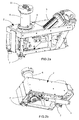
- This device of actuating tools or toolbox device comprises a frame or support structure 1 on which are mounted four modules 2, each intended to actuate a locking / unlocking mechanism of a battery of a motor vehicle.
- Each module 2 is in the form of a separate element of the support structure 1, possibly fixed in a removable manner.
- the support structure 1 has a T-shape, particularly suitable for motor vehicle batteries positioned in the trunk of the vehicle. Alternatively, the support structure 1 could have other shapes.
- Each module 2 comprises one or more actuating means, including one or more simple and standard motors and a gripping system 6 locking mechanisms, whose function is to actuate the locking mechanism and unlocking a battery of a vehicle automobile.
- the number of actuating means is more particularly related to the number of movements required for the implementation of the locking and / or unlocking of the battery.
- the gripping system 6 is in a cylindrical shape, extending above the upper surface of the module 2, to allow its upper end 11 to come into contact with the locks of a battery of a motor vehicle .
- Each module 2 further comprises an electrical connection for the power supply of its motors, as well as an interface 7 for a flexible connection with the support structure 1, in order to allow the toolbox device to correctly position the gripping system on a motor vehicle.
- the interface 7 comprises movement-limiting elements, for example including balls associated with elastic studs, which make it possible to generate degrees of freedom, such as rotation, between the different modules 2 and the support structure 1 , allowing to adjust the position of the modules 2 with respect to a battery to lock / unlock.
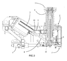
- each module 2 comprises several complementary actuating means, particularly visible on the figure 3 , able to allow the implementation of all the movements necessary for locking / unlocking.
- a first actuating means 3 comprising for example a motor and an electric jack, is intended to effect a disengagement of the gripping system 6 for the recovery of forces between the battery and the body of the motor vehicle.
- a second actuating means 4, comprising for example an electric jack, is intended for locking the end 11 of the gripping system 6 on a corresponding means of the battery latch on the motor vehicle.
- This second actuating means 4 may in particular allow locking of the toolbox device on mushroom-shaped elements, which will be described later with reference to the figure 4 .
- a third actuating means 5 for example of the electric jack type, allows the actual actuation of the locking / unlocking movement of the battery, for example according to a rotational movement of a quarter or a half. turn, as explained later.
- Each module 2 further comprises a cam system 8 positioned at the end of the first actuating means 3, allowing the multiplication of the necessary forces.
- each module 2 comprises a system of "roller” 9, or any equivalent system, the function of which is the retention of forces at the support structure 1 to prevent damage to the toolbox device when setting in motion the first means actuating device 3 and actuating the cam system 8 in a substantially horizontal direction.
- the module 2 further comprises a means of internal looping efforts to relieve the forces transmitted to the support structure 1 and more generally to the entire battery exchange device.
- This means of internal looping of the forces is more precisely arranged in the zone A represented on the figure 2a .
- the vertical component of the force is transmitted to the compression axis 15 and the reaction of this component is taken up by the system of compression. gripping 6 at the zone A.
- the support structure 1 does not support any effort.
- the horizontal component of the force, coming from the rod 10 of the first actuating means 3 is transmitted to the compression axis 15 and the reaction of this component is taken up by the module 2 via the reaction roller 9. Structure 1 does not support this effort either.
- the support structure 1 may have other geometries and receive a different number of modules 2.
- Each module 2 may comprise a different number of gripping systems 6 and / or actuating means, motors, but preferably between three to six.
- the number of motors and actuating means is directly related to the number of movements to be performed to implement the locking and unlocking of a battery.
- the independent actuators can be electrical, hydraulic, kinematic cam, etc.
- the precise structure of the toolbox device in terms of number of modules, actuating means and gripping systems will in fact depend on the locking mechanism of the battery on the motor vehicle.
- the same module 2 can be mounted on different support structures 1, which allows the use of standard modules 2 for all types of batteries and motor vehicles.
- each module 2 having exactly the number of actuating means associated with the movements required for locking / unlocking, such a toolbox device thus comprises standard interfaces perfectly adapted to the corresponding type of battery and / or vehicle.
- each module 2 can be replaced independently of the rest of the toolbox device structure. This allows the replacement of the only defective module if necessary, without touching the rest of the toolbox device. For this, the link interface of each module allows a removable link.
- a lifting system and possibly moving the toolbox device is arranged at a battery exchange station. It is possible to provide a lifting system which is not provided with a displacement function and which is only limited to a lifting function, that is to say to the substantially vertical movement of the toolbox device.
- the displacement function will then be obtained by a separate displacement system that can either move the battery to be mounted or the vehicle on which it is desired to mount the battery.
- the toolbox device can for example be moved by a roller-type device operating with the aid of conveying rails.
- a robot can be used for moving the toolbox device, the latter then comprising a connection interface for example in the form of grips.
- the lifting and moving system of the toolbox device allows its positioning under a motor vehicle, from which one accesses the battery. It allows the connection of the toolbox device with the lock of the battery of the motor vehicle, by a substantially vertical movement of the toolbox device.
- at most three gripping systems 6 of the toolbox device are correctly positioned, since they are by definition coplanar, before allowing the positioning of the fourth gripping system, or even other gripping system if there has more than four, which accesses (s) to a precise positioning thanks to their relative mobility to the support structure 1 due to their connection having at least one degree of freedom, described above, which makes it possible to catch any geometric dispersions.
- These two phases of positioning of the toolbox device can also be coupled.
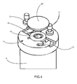
- the figure 4 illustrates a phase of approach of the upper part 11 of a gripping system 6 to a latch corresponding now a battery on a motor vehicle, implemented by a lifting system as explained above. Only the lower connecting portion 20 and the two lateral connecting elements 21 in the form of locking mushrooms are shown, to simplify the figure.
- the end 11 of the gripping system 6 comprises two slots 12 arranged symmetrically about a connecting element 13 which is in the form of a hexagonal opening adapted to receive a corresponding hexagonal rod, not shown, disposed under the surface of the connecting element 20 of the lock, or which may alternatively be any other flat / flat type connection.
- Each lumen 12 has a substantially circular portion, of significant size corresponding to a mushroom 21 so as to insert such a mushroom by this circular portion.
- each lumen 12 includes a narrower portion, forming a portion of an arc of a circle, within which the narrower portion of a mushroom 21 can be moved after its insertion into the circular opening, so as to obtain its locking and thus the locked attachment of the gripping system 6 on the battery lock.
- This locked attachment of a gripping system on a battery lock is implemented by its rotation by the second actuating means of the module considered, as explained above.
- this attachment could be obtained by another geometry and / or other movements, such as a translation. This operation is carried out, preferably at the same time, for all the modules of the toolbox device, in order to obtain the locked attachment of this toolbox device on the battery lock.
- the actuation of the gripping systems 6 of the toolbox device can act on the locks of the battery to lock or unlock.
- the toolbox device is therefore suitable for locking and / or unlocking a battery attached to a motor vehicle.
- it can perform a second function of holding and transporting the battery, which adds to its first function of actuating the locking and unlocking mechanisms, in particular to evacuate an empty battery after unlocking, to the using a lifting and moving system.
- the toolbox device also allows the approach of a new charged battery for fixing this new battery charged to replace the empty battery.
Description
- La présente invention se rapporte à un dispositif d'actionnement pour le verrouillage et/ou déverrouillage d'un conteneur d'énergie de type batterie d'un véhicule automobile électrique. Par la suite, le terme batterie sera utilisé pour une raison de simplification. L'invention porte aussi sur un système de remplacement d'une batterie ou de tout conteneur d'énergie d'un véhicule automobile incluant un tel dispositif d'actionnement ainsi que sur une station de remplacement de batterie utilisant un tel système.
- Certains véhicules automobiles, comme les véhicules électriques ou hybrides, comprennent une batterie pour l'alimentation d'un moteur d'entraînement électrique. Il peut se révéler intéressant d'échanger cette batterie lorsque son niveau d'énergie est faible contre une nouvelle batterie chargée. Ceci peut être fait dans une station similaire à une station service dans laquelle on peut remplir un réservoir d'essence d'un véhicule automobile.
- Le document
US 2007/0113921 décrit un dispositif selon le préambule de la revendication 1. - On connaît du document
US 5 612 606 une station d'échange de batterie électrique d'alimentation d'un moteur d'entraînement d'un véhicule électrique et un procédé pour réaliser un tel échange. Dans la station d'échange décrite, le conducteur positionne approximativement le véhicule dans un rail, contre une butée longitudinale par rapport aux équipements de la station. Par la suite, dans des phases plus ou moins automatiques, des moyens mobiles de dépose de la batterie électrique et d'assemblage de la nouvelle batterie au véhicule viennent se positionner relativement au véhicule grâce à des capteurs. - Une difficulté pour la mise en place d'un tel concept d'échange de batteries réside dans le fait qu'il existe une multitude de véhicules automobiles pouvant comprendre des batteries de type différent, fixées de manière différente sur le véhicule automobile. Or il n'est pas envisageable économiquement de multiplier les dispositifs automatiques de dépose et remplacement de ces différents types de batteries ni de mettre en place une solution manuelle en raison de son coût et du poids des batteries.
- Ainsi, pour rendre possible un déploiement aisé des stations d'échange de batteries (nécessitant peu de compétence technologique), il est nécessaire de rendre fiable, robuste, flexible et universel le fonctionnement de ces stations.
- Le but de l'invention est donc de fournir une solution de remplacement d'une batterie de véhicule automobile atteignant les objectifs mentionnés ci-dessus.
- Le concept de l'invention repose sur un dispositif universel et standard comprenant des outils participant à l'actionnement des mécanismes de verrouillage et/ou déverrouillage d'une batterie montée sur un véhicule automobile, que nous appellerons par sa dénomination anglo-saxonne « toolbox » pour une raison de simplification de la description.
- Plus précisément, l'invention repose sur un dispositif toolbox pour l'actionnement du verrouillage et/ou déverrouillage d'une batterie d'alimentation d'un moteur d'entraînement d'un véhicule automobile, caractérisé en ce qu'il comprend une structure support supportant plusieurs modules distincts, comprenant chacun au moins un système de préhension d'un mécanisme de verrouillage/déverrouillage de la batterie et au moins un moyen d'actionnement, le nombre des moyens d'actionnement étant lié au nombre de mouvements à effectuer pour mettre en oeuvre le verrouillage/déverrouillage de la batterie.
- Le dispositif toolbox peut comprendre quatre modules comprenant chacun un système de préhension.
- Le dispositif toolbox peut comprendre au moins un module comprenant une interface de liaison lui permettant au moins un degré de liberté par rapport à la structure support.
- Le dispositif toolbox peut comprendre un module comprenant un premier moyen d'actionnement apte à effectuer un débrayage d'un système de préhension.
- Le module peut comprendre un système de came positionné à l'extrémité du premier moyen d'actionnement pour permettre le transfert et la démultiplication des efforts nécessaires.
- Le module peut comprendre un second moyen d'actionnement destiné au verrouillage et déverrouillage de l'extrémité d'un système de préhension sur un moyen correspondant d'un verrou de la batterie d'un véhicule automobile.
- L'extrémité du système de préhension du module peut comprendre deux lumières aptes à une liaison avec un moyen correspondant en forme de champignon du verrou de la batterie d'un véhicule automobile.
- Le dispositif toolbox peut comprendre un module comprenant un troisième moyen d'actionnement permettant l'actionnement du verrouillage/déverrouillage de la batterie d'un véhicule automobile.
- Cet actionnement du verrouillage/déverrouillage de la batterie d'un véhicule automobile peut être obtenu par un mouvement de translation et un mouvement de rotation du système de préhension.
- Le dispositif toolbox peut comprendre un module comprenant un système de « galet » pour limiter les efforts au niveau de la structure support et éviter sa détérioration.
- L'invention porte aussi sur un système de remplacement d'une batterie d'un véhicule automobile, caractérisé en ce qu'il comprend un dispositif toolbox tel que décrit précédemment et un dispositif de levage de ce dispositif toolbox, permettant son déplacement vertical.
- L'invention porte aussi sur une station de remplacement d'une batterie d'alimentation d'un moteur d'entraînement d'un véhicule automobile, caractérisée en ce qu'elle comprend un dispositif toolbox tel que décrit précédemment pour le remplacement d'une batterie d'un véhicule automobile.
- Ces objets, caractéristiques et avantages de la présente invention seront exposés en détail dans la description suivante d'un mode d'exécution particulier fait à titre non-limitatif en relation avec les figures jointes parmi lesquelles :
- La
figure 1 représente une vue en perspective d'un dispositif toolbox selon un mode d'exécution de l'invention. - Les
figures 2a et 2b représentent des vues en perspective respectivement de dessus et de dessous d'un module du dispositif toolbox selon le mode d'exécution de l'invention. - La
figure 3 représente une vue de côté en coupe d'un module du dispositif toolbox selon le mode d'exécution de l'invention. - La
figure 4 représente en perspective la liaison entre un dispositif toolbox selon le mode d'exécution de l'invention et un verrou de batterie d'un véhicule automobile. - Le concept de l'invention repose sur un dispositif d'outils d'actionnement dit «dispositif toolbox », qui comprend un certain nombre de composants standards et modulaires afin d'obtenir un dispositif adapté pour une intervention sur tous types de batteries et tous véhicules automobiles. Ce dispositif toolbox de l'invention représente un adaptateur cinématique universel, permettant de s'adapter à la plus grande diversité de batteries au moindre coût.
- Les figures représentent un dispositif toolbox selon un mode d'exécution de l'invention. Ce dispositif d'outils d'actionnement ou dispositif toolbox comprend un châssis ou structure support 1 sur laquelle sont montés quatre modules 2, destinés chacun à actionner un mécanisme de verrouillage/déverrouillage d'une batterie d'un véhicule automobile. Chaque module 2 se présente sous la forme d'un élément distinct de la structure support 1, éventuellement fixé de manière amovible. La structure support 1 présente une forme en T, particulièrement adaptée aux batteries de véhicule automobile positionnées dans le coffre du véhicule. En variante, la structure support 1 pourrait présenter d'autres formes.
- Chaque module 2, plus particulièrement représenté par les
figures 2 et3 , comprend un ou plusieurs moyens d'actionnements, incluant un ou plusieurs moteurs simples et standards et un système de préhension 6 des mécanismes de verrouillage, dont la fonction est d'actionner le mécanisme de verrouillage et déverrouillage d'une batterie d'un véhicule automobile. Le nombre de moyens d'actionnement est plus particulièrement lié au nombre de mouvements nécessaires pour la mise en oeuvre du verrouillage et/ou du déverrouillage de la batterie. - Le système de préhension 6 se présente sous une forme cylindrique, s'étendant au-dessus de la surface supérieure du module 2, afin de permettre à son extrémité supérieure 11 de venir en liaison avec les verrous d'une batterie d'un véhicule automobile. Chaque module 2 comprend de plus une connexion électrique pour l'alimentation de ses moteurs, ainsi qu'une interface 7 pour une liaison flexible avec la structure support 1, afin de permettre au dispositif toolbox de positionner correctement sur un véhicule automobile le système de préhension 6. Pour cela, l'interface 7 comprend des éléments limiteur de mouvements, par exemple incluant des billes associées à des plots élastiques, qui permettent de générer des degrés de libertés, comme une rotation, entre les différents modules 2 et la structure support 1, permettant d'ajuster la position des modules 2 par rapport à une batterie à verrouiller/déverrouiller. Cette solution permet ainsi de s'adapter à la dispersion géométrique des différents composants du véhicule automobile et du dispositif toolbox.
- Sur le mode d'exécution représenté, chaque module 2 comprend plusieurs moyens d'actionnement complémentaires, particulièrement visibles sur la
figure 3 , aptes à permettre la mise en oeuvre de l'ensemble des mouvements nécessaires au verrouillage/déverrouillage. Un premier moyen d'actionnement 3, comprenant par exemple un moteur et un vérin électrique, est destiné à effectuer un débrayage du système de préhension 6 pour la reprise des efforts entre la batterie et la caisse du véhicule automobile. Un second moyen d'actionnement 4, comprenant par exemple un vérin électrique, est destiné au verrouillage de l'extrémité 11 du système de préhension 6 sur un moyen correspondant du verrou de la batterie sur le véhicule automobile. Ce second moyen d'actionnement 4 peut notamment permettre le verrouillage du dispositif toolbox sur des éléments en forme de champignons, qui seront décrits ultérieurement en référence à lafigure 4 . Enfin, un troisième moyen d'actionnement 5, par exemple de type vérin électrique, permet l'actionnement proprement dit du mouvement de verrouillage/déverrouillage de la batterie, selon par exemple un mouvement de rotation d'un quart ou d'un demi-tour, comme explicité par la suite. - Chaque module 2 comprend de plus un système de came 8 positionné à l'extrémité du premier moyen d'actionnement 3, permettant la démultiplication des efforts nécessaires. Enfin, chaque module 2 comprend un système de « galet » 9, ou tout système équivalent, dont la fonction est la retenue des efforts au niveau de la structure support 1 pour éviter la détérioration du dispositif toolbox lors de la mise en mouvement du premier moyen d'actionnement 3 et de l'actionnement du système à came 8 dans une direction sensiblement horizontale.
- Plus précisément, lorsque le vérin du premier moyen d'actionnement 3 reçoit une commande de sortie de la tige 10 de son vérin vers le bas, cette dernière agit sur le système de came 8 qui permet le passage des efforts de compression de rondelles de Belleville, pour finalement déplacer l'axe de compression 15 positionné au sein du système de préhension 6. Lors de cette opération, un galet de réaction 9 absorbe les efforts subis lors du déplacement de cet axe de compression 15.
- De manière optionnelle mais avantageuse, le module 2 comprend de plus un moyen de rebouclage interne des efforts afin de soulager les efforts transmis à la structure support 1 et plus globalement à tout le dispositif d'échange de batterie. Ce moyen de rebouclage interne des efforts se trouve plus précisément aménagé dans la zone A représentée sur la
figure 2a . La composante verticale de l'effort est transmise à l'axe de compression 15 et la réaction de cette composante est reprise par le système de préhension 6 au niveau de la zone A. La structure support 1 ne supporte aucun effort. De plus, la composante horizontale de l'effort, provenant de la tige 10 du premier moyen d'actionnement 3, est transmise à l'axe de compression 15 et la réaction de cette composante est reprise par le module 2 via le galet de réaction 9. La structure 1 ne supporte pas non plus cet effort. - Bien entendu, l'invention ne se limite pas au mode d'exécution décrit ci-dessus. Notamment, la structure support 1 peut présenter d'autres géométries et recevoir un nombre différent de modules 2. Chaque module 2 peut comprendre un nombre différent de systèmes de préhension 6 et/ou de moyens d'actionnement, de moteurs, mais de préférence entre trois à six. En général, le nombre de moteurs et de moyens d'actionnement est directement lié au nombre de mouvements à effectuer pour mettre en oeuvre le verrouillage et le déverrouillage d'une batterie. De plus, les actionneurs indépendants peuvent être de type électrique, hydraulique, à cinématique à came, etc. Finalement, la structure précise du dispositif toolbox en termes de nombre de modules, de moyens d'actionnement et de systèmes de préhension dépendra en fait du mécanisme de verrouillage de la batterie sur le véhicule automobile. Selon un élément avantageux de l'invention, un même module 2 peut être monté sur des structures support 1 différentes, ce qui permet d'utiliser des modules 2 standard pour tous types de batteries et véhicules automobiles. De même, chaque module 2 comportant exactement le nombre de moyens d'actionnement associés aux mouvements nécessaires au verrouillage/déverrouillage, un tel dispositif toolbox comporte donc des interfaces standards parfaitement adaptées au type de batterie et/ou de véhicule correspondants.
- Selon un mode d'exécution avantageux, chaque module 2 peut être remplacé indépendamment du reste de la structure du dispositif toolbox. Cela permet le remplacement du seul module défectueux si nécessaire, sans toucher au reste du dispositif toolbox. Pour cela, l'interface de liaison de chaque module lui permet une liaison amovible.
- Le fonctionnement du dispositif toolbox selon l'invention va maintenant être explicité. Un système de levage et éventuellement de déplacement du dispositif toolbox est aménagé au niveau d'une station d'échange de batterie. On peut prévoir un système de levage non pourvu de fonction de déplacement et uniquement limité à une fonction de levage, c'est-à-dire au déplacement sensiblement vertical du dispositif toolbox. La fonction de déplacement sera alors obtenue par un système de déplacement distinct pouvant soit déplacer la batterie à monter soit le véhicule sur laquelle on souhaite monter la batterie. Le dispositif toolbox peut par exemple être déplacé par un dispositif de type rouleaux fonctionnant à l'aide de rails de convoyage. En variante, un robot peut être utilisé pour le déplacement du dispositif toolbox, ce dernier comprenant alors une interface de liaison par exemple en forme de poignées de préhension.
- Le système de levage et déplacement du dispositif toolbox permet son positionnement sous un véhicule automobile, d'où on accède à la batterie. Il permet la connexion du dispositif toolbox avec le verrou de la batterie du véhicule automobile, par un déplacement sensiblement vertical du dispositif toolbox. Pour cela et d'abord, au plus trois systèmes de préhension 6 du dispositif toolbox sont correctement positionnés, puisqu'ils sont par définition coplanaires, avant de permettre le positionnement du quatrième système de préhension, voire des autres système de préhension s'il y en a plus de quatre, qui accède(nt) à un positionnement précis grâce à leur mobilité relative à la structure support 1 du fait de leur liaison présentant au moins un degré de liberté, décrite précédemment, qui permet de rattraper les éventuelles dispersions géométriques. Ces deux phases de positionnement du dispositif toolbox peuvent aussi être couplées.
- La
figure 4 illustre une phase d'approche de la partie haute 11 d'un système de préhension 6 vers un verrou correspondant maintenant une batterie sur un véhicule automobile, mise en oeuvre par un système de levage tel qu'explicité ci-dessus. Seuls la partie inférieure de liaison 20 et les deux éléments de liaison latéraux 21 en forme de champignons de fixation du verrou sont représentés, pour simplifier la figure. L'extrémité 11 du système de préhension 6 comprend deux lumières 12 disposées symétriquement autour d'un élément de liaison 13 qui se présente sous la forme d'une ouverture hexagonale apte à recevoir une tige hexagonale correspondante, non représentée, disposée sous la surface de l'élément de liaison 20 du verrou, ou qui peut être en variante toute autre liaison de type plat/méplat. Chaque lumière 12 présente une partie sensiblement circulaire, de taille importante correspondant à un champignon 21 de sorte de pouvoir insérer un tel champignon par cette partie circulaire. Ensuite, chaque lumière 12 comprend une partie plus étroite, formant une portion d'arc de cercle, au sein de laquelle peut se déplacer la partie plus étroite d'un champignon 21 après son insertion dans l'ouverture circulaire, de sorte d'obtenir son verrouillage et donc la fixation verrouillée du système de préhension 6 sur le verrou de la batterie. Cette fixation verrouillée d'un système de préhension sur un verrou de batterie est mise en oeuvre par sa rotation par le second moyen d'actionnement du module considéré, comme explicité précédemment. En variante, cette fixation pourrait être obtenue par une autre géométrie et/ou d'autres mouvements, comme une translation. Cette opération est réalisée, de préférence en même temps, pour tous les modules du dispositif toolbox, afin d'obtenir la fixation verrouillée de ce dispositif toolbox sur le verrou de la batterie. - Ensuite, la partie centrale 13 de la liaison entre le système de préhension et le verrou se déplace en translation verticale, par l'intermédiaire de l'axe de compression 15 décrit précédemment, pour venir en appui sur un piston et débrayer le verrou, avant de le verrouiller ou le déverrouiller par un mouvement de rotation. Ces deux mouvements sont mis en oeuvre par le troisième moyen d'actionnement explicité précédemment.
- Ainsi, l'actionnement des systèmes de préhension 6 du dispositif toolbox permet d'agir sur les verrous de la batterie, pour les verrouiller ou les déverrouiller. Le dispositif toolbox est donc apte au verrouillage et/ou déverrouillage d'une batterie fixée sur un véhicule automobile. En variante, il peut remplir une seconde fonction de maintien et transport de la batterie, qui s'ajoute à sa première fonction d'actionnement des mécanismes de verrouillage et déverrouillage, afin notamment d'évacuer une batterie vide après son déverrouillage, à l'aide d'un système de levage et déplacement. De manière inverse, le dispositif toolbox permet aussi l'approche d'une nouvelle batterie chargée, pour la fixation de cette nouvelle batterie chargée en remplacement de la batterie vide.
- Ainsi, la solution décrite présente les avantages suivants :
- elle est adaptée à une standardisation des opérations de verrouillage et déverrouillage d'une batterie sur un véhicule automobile, du fait de sa grande flexibilité par l'utilisation de composants simples et standards adaptés pour une multitude de mouvements différents, pour transférer efficacement les efforts et avec une précision géométrique importante ;
- elle présente un coût réduit ;
- elle est adaptée à une implémentation dans une station-service d'échange de batteries, car elle représente un système à interface standard et encombrement optimisé ;
- elle est adaptée à la constitution d'un réseau de stations-services d'échange de batterie universelles, qui peuvent être adaptées au type de véhicules pris en charge.
Claims (12)
- Dispositif toolbox pour l'actionnement du verrouillage et/ou déverrouillage d'une batterie d'alimentation d'un moteur d'entraînement d'un véhicule automobile, caractérisé en ce qu'il comprend une structure support (1) supportant plusieurs modules (2) distincts, comprenant chacun au moins un système de préhension (6) d'un mécanisme de verrouillage/déverrouillage de la batterie et au moins un moyen d'actionnement (3, 4, 5), le nombre des moyens d'actionnement étant lié au nombre de mouvements à effectuer pour mettre en oeuvre le verrouillage/déverrouillage de la batterie.
- Dispositif toolbox selon la revendication précédente, caractérisé en ce qu'il comprend quatre modules (2) comprenant chacun un système de préhension (6).
- Dispositif toolbox selon l'une des revendications précédentes, caractérisé en ce qu'il comprend au moins un module (2) comprenant une interface (7) de liaison lui permettant au moins un degré de liberté par rapport à la structure support (1).
- Dispositif toolbox selon l'une des revendications précédentes, caractérisé en ce qu'il comprend un module (2) comprenant un premier moyen d'actionnement (3) apte à effectuer un débrayage d'un système de préhension (6).
- Dispositif toolbox selon la revendication précédente, caractérisé en ce que le module (2) comprend un système de came (8) positionné à l'extrémité du premier moyen d'actionnement (3) pour permettre le transfert et la démultiplication des efforts nécessaires.
- Dispositif toolbox selon l'une des revendications précédentes, caractérisé en ce qu'il comprend un module (2) comprenant un second moyen d'actionnement (4) destiné au verrouillage et déverrouillage de l'extrémité (11) d'un système de préhension (6) sur un moyen correspondant d'un verrou de la batterie d'un véhicule automobile.
- Dispositif toolbox selon la revendication précédente, caractérisé en ce que l'extrémité (11) du système de préhension (6) du module (2) comprend deux lumières (12) aptes à une liaison avec un moyen (21) correspondant en forme de champignon du verrou de la batterie d'un véhicule automobile.
- Dispositif toolbox selon l'une des revendications précédentes, caractérisé en ce qu'il comprend un module (2) comprenant un troisième moyen d'actionnement (5) permettant l'actionnement du verrouillage/déverrouillage de la batterie d'un véhicule automobile.
- Dispositif toolbox selon la revendication précédente, caractérisé en ce que l'actionnement du verrouillage/déverrouillage de la batterie d'un véhicule automobile est obtenu par un mouvement de translation et un mouvement de rotation du système de préhension (6).
- Dispositif toolbox selon l'une des revendications précédentes, caractérisé en ce qu'il comprend un module (2) comprenant un système de « galet » (9) pour limiter les efforts au niveau de la structure support (1) et éviter sa détérioration.
- Système de remplacement d'une batterie d'un véhicule automobile, caractérisé en ce qu'il comprend un dispositif toolbox selon l'une des revendications précédentes et un dispositif de levage (13) de ce dispositif toolbox, permettant son déplacement vertical.
- Station de remplacement d'une batterie d'alimentation d'un moteur d'entraînement d'un véhicule automobile, caractérisée en ce qu'elle comprend un dispositif toolbox selon l'une des revendications 1 à 10 pour le remplacement d'une batterie d'un véhicule automobile.
Applications Claiming Priority (2)
| Application Number | Priority Date | Filing Date | Title |
|---|---|---|---|
| FR1050912A FR2956072B1 (fr) | 2010-02-10 | 2010-02-10 | Dispositif pour le remplacement d'une batterie d'alimentation d'un moteur d'entrainement d'un vehicule automobile |
| PCT/FR2011/050273 WO2011098725A1 (fr) | 2010-02-10 | 2011-02-09 | Dispositif pour le remplacement d'une batterie d'alimentation d'un moteur d'entrainement d'un vehicule automobile |
Publications (2)
| Publication Number | Publication Date |
|---|---|
| EP2534020A1 EP2534020A1 (fr) | 2012-12-19 |
| EP2534020B1 true EP2534020B1 (fr) | 2015-01-07 |
Family
ID=42340679
Family Applications (1)
| Application Number | Title | Priority Date | Filing Date |
|---|---|---|---|
| EP11708913.6A Not-in-force EP2534020B1 (fr) | 2010-02-10 | 2011-02-09 | Dispositif pour le remplacement d'une batterie d'alimentation d'un moteur d'entrainement d'un vehicule automobile |
Country Status (11)
| Country | Link |
|---|---|
| US (1) | US9162653B2 (fr) |
| EP (1) | EP2534020B1 (fr) |
| JP (1) | JP2013519565A (fr) |
| KR (1) | KR101791509B1 (fr) |
| CN (1) | CN102791542B (fr) |
| AU (1) | AU2011214226B2 (fr) |
| BR (1) | BR112012019816A2 (fr) |
| CA (1) | CA2789828A1 (fr) |
| FR (1) | FR2956072B1 (fr) |
| IL (1) | IL221348A0 (fr) |
| WO (1) | WO2011098725A1 (fr) |
Families Citing this family (18)
| Publication number | Priority date | Publication date | Assignee | Title |
|---|---|---|---|---|
| FR2954592B1 (fr) * | 2009-12-21 | 2012-01-06 | Renault Sa | Procede et syteme de montage ou demontage d'une batterie d'un vehicule automobile. |
| TWI561408B (en) * | 2011-11-07 | 2016-12-11 | Aleees Eco Ark Cayman Co Ltd | Battery assembly with fixing and anti-theft function |
| KR101393848B1 (ko) * | 2012-10-09 | 2014-05-12 | 기아자동차주식회사 | 승용 전기차의 고전압 배터리팩 |
| US9969283B2 (en) * | 2013-09-10 | 2018-05-15 | General Electric Company | Battery changing system and method |
| CN103661307B (zh) * | 2013-12-20 | 2016-03-30 | 唐山轨道客车有限责任公司 | 蓄电池组安装及拆卸装置 |
| EP3108556B1 (fr) * | 2014-02-21 | 2019-04-10 | The UAB Research Foundation | Procédé de détection d'état à phase ouverte d'un transformateur |
| ES2583427B1 (es) * | 2015-03-20 | 2017-06-29 | Industrias Maxi, S.A. | Procedimiento de montaje de un dispositivo para reemplazo de baterias en vehículos eléctricos y útiles de conformado. |
| DE102015112138A1 (de) * | 2015-07-24 | 2017-01-26 | Dr. Ing. H.C. F. Porsche Aktiengesellschaft | Unterboden eines elektrisch angetriebenen Kraftfahrzeugs |
| EP3136528B1 (fr) * | 2015-08-31 | 2020-04-22 | Siemens Aktiengesellschaft | Procede de protection differentielle, dispositif de protection differentielle et systeme de protection differentielle |
| US9873408B2 (en) * | 2016-05-11 | 2018-01-23 | Peter D. Capizzo | Device for refueling, exchanging, and charging power sources on remote controlled vehicles, UAVs, drones, or any type of robotic vehicle or machine with mobility |
| CN105946812B (zh) * | 2016-06-23 | 2017-12-19 | 蔚来汽车有限公司 | 锁体组件、动力电池、其锁止机构及使用方法、交通工具 |
| DE102017123208A1 (de) * | 2017-10-06 | 2019-04-11 | Kiekert Ag | Elektrische Anschlussvorrichtung für Elektro- oder Hybridkraftfahrzeuge |
| CN112455274B (zh) * | 2019-09-06 | 2023-12-01 | 杭州海康机器人股份有限公司 | Agv的电池拆装机构及电池拆卸方法 |
| CN111618625B (zh) * | 2020-06-04 | 2021-11-09 | 无锡齐高科技有限公司 | 手机电池壳模具板件加工用工装 |
| US11857886B2 (en) | 2020-07-01 | 2024-01-02 | Universal City Studios Llc | Method of bogie replacement for turntable station |
| CN112389179B (zh) * | 2020-10-10 | 2022-04-26 | 东风汽车集团有限公司 | 一种车辆电池包加解锁装置及总成 |
| CN114770110B (zh) * | 2022-04-15 | 2024-03-05 | 杭州华循科技有限公司 | 一种动力电池软铜排自动化生产线 |
| CN115416541B (zh) * | 2022-11-04 | 2023-05-09 | 蓝谷智慧(北京)能源科技有限公司 | 电池加解锁机构、换电平台及换电站 |
Family Cites Families (19)
| Publication number | Priority date | Publication date | Assignee | Title |
|---|---|---|---|---|
| US3826115A (en) * | 1972-09-12 | 1974-07-30 | B Davis | Battery locking device |
| US4249403A (en) * | 1979-07-25 | 1981-02-10 | Calvin Littlejohn | Battery locking means |
| US5052198A (en) * | 1990-07-30 | 1991-10-01 | Elektrek Partnership | Battery lock and hold-down device |
| EP0575864A3 (en) * | 1992-06-16 | 1994-06-01 | Baer Hans | Method and device for energy supply |
| DE4229687A1 (de) * | 1992-09-05 | 1994-03-10 | Dieter Kitto Werkzeug Und Masc | Batteriewechselstation für elektrisch angetriebene Kraftfahrzeuge |
| JP3022086B2 (ja) * | 1993-09-20 | 2000-03-15 | 日産自動車株式会社 | 電気自動車のバッテリ固定構造 |
| US5612606A (en) | 1994-09-15 | 1997-03-18 | David C. Guimarin | Battery exchange system for electric vehicles |
| DE19621668A1 (de) * | 1996-05-30 | 1997-12-04 | Uwe Kochanneck | Multiblock-Robot-System |
| JP2006334760A (ja) * | 2005-06-06 | 2006-12-14 | Mazda Motor Corp | 可変多軸締付装置およびその設計支援装置 |
| US7602143B2 (en) * | 2005-11-04 | 2009-10-13 | Peter David Capizzo | System for replenishing energy sources onboard different types of automotive vehicles |
| DE102007032210B4 (de) * | 2007-04-19 | 2010-04-08 | Höltzel, Thomas | Verfahren und Vorrichtung zum Austausch von Akkumulatoren für Elektrofahrzeuge |
| FR2933656B1 (fr) * | 2008-07-08 | 2010-12-03 | Renault Sas | Dispositif de verrouillage et deverouillage automatiques d'un bac batterie de vehicule automobile electrique, vehicule et station d'echange de batteries equipes d'un tel dispositif |
| US8006793B2 (en) * | 2008-09-19 | 2011-08-30 | Better Place GmbH | Electric vehicle battery system |
| FR2936760B1 (fr) | 2008-10-07 | 2010-10-15 | Renault Sas | Systeme de fixation d'un pack de batterie et procede de montage/demontage automatisable associe. |
| FR2946305A1 (fr) | 2009-06-05 | 2010-12-10 | Julien Armand Bouvard | Station service automatisee de changement de batteries pour vehicules a propulsion electrique |
| DE102009025052A1 (de) * | 2009-06-10 | 2011-04-28 | Gottwald Port Technology Gmbh | System zum Wechseln einer Batterie eines flurgebundenen Tranportfahrzeuges, insbesondere eines fahrerlosen Schwerlast-Transportfahrzeuges für ISO-Container |
| DE102009045827A1 (de) * | 2009-10-20 | 2011-04-21 | Zf Friedrichshafen Ag | Zusatzbetätigungsvorrichtung, Gehäuse und Drehverriegelungsvorrichtung für ein Kraftfahrzeug |
| FR2952334B1 (fr) * | 2009-11-12 | 2011-10-28 | Renault Sa | Dispositif pour le remplacement d'une batterie d'alimentation d'un moteur d'entrainement d'un vehicule automobile. |
| FR2954591B1 (fr) * | 2009-12-21 | 2012-01-13 | Renault Sa | Outil de montage/demontage d'une batterie d'un vehicule automobile |
-
2010
- 2010-02-10 FR FR1050912A patent/FR2956072B1/fr not_active Expired - Fee Related
-
2011
- 2011-02-09 BR BR112012019816A patent/BR112012019816A2/pt not_active IP Right Cessation
- 2011-02-09 US US13/578,398 patent/US9162653B2/en not_active Expired - Fee Related
- 2011-02-09 CA CA2789828A patent/CA2789828A1/fr not_active Abandoned
- 2011-02-09 EP EP11708913.6A patent/EP2534020B1/fr not_active Not-in-force
- 2011-02-09 JP JP2012552446A patent/JP2013519565A/ja active Pending
- 2011-02-09 AU AU2011214226A patent/AU2011214226B2/en not_active Ceased
- 2011-02-09 KR KR1020127023512A patent/KR101791509B1/ko active IP Right Grant
- 2011-02-09 WO PCT/FR2011/050273 patent/WO2011098725A1/fr active Application Filing
- 2011-02-09 CN CN201180013120.XA patent/CN102791542B/zh not_active Expired - Fee Related
-
2012
- 2012-08-08 IL IL221348A patent/IL221348A0/en unknown
Also Published As
| Publication number | Publication date |
|---|---|
| CN102791542B (zh) | 2015-08-19 |
| AU2011214226B2 (en) | 2016-06-02 |
| IL221348A0 (en) | 2012-10-31 |
| CA2789828A1 (fr) | 2011-08-18 |
| AU2011214226A1 (en) | 2012-09-20 |
| FR2956072B1 (fr) | 2012-02-24 |
| KR20120130202A (ko) | 2012-11-29 |
| EP2534020A1 (fr) | 2012-12-19 |
| WO2011098725A1 (fr) | 2011-08-18 |
| FR2956072A1 (fr) | 2011-08-12 |
| US9162653B2 (en) | 2015-10-20 |
| BR112012019816A2 (pt) | 2016-05-17 |
| KR101791509B1 (ko) | 2017-11-20 |
| JP2013519565A (ja) | 2013-05-30 |
| CN102791542A (zh) | 2012-11-21 |
| US20130031776A1 (en) | 2013-02-07 |
Similar Documents
| Publication | Publication Date | Title |
|---|---|---|
| EP2534020B1 (fr) | Dispositif pour le remplacement d'une batterie d'alimentation d'un moteur d'entrainement d'un vehicule automobile | |
| EP2499013B1 (fr) | Dispositif pour le remplacement d'une batterie d'alimentation d'un moteur d'entrainement d'un vehicule automobile | |
| EP2516220B1 (fr) | Procede et systeme de montage ou demontage d'une batterie d'un vehicule automobile | |
| EP2825404B1 (fr) | Système de verrouillage/déverrouillage d'un objet sur une structure à éléments d'appui et d'alignement intégrés aux outils | |
| EP2517281B1 (fr) | Dispositif de fixation amovible d'une batterie d'un vehicule automobile | |
| EP2598358B1 (fr) | Dispositif de fixation amovible d'une batterie d'un vehicule automobile | |
| EP2825405B1 (fr) | Système de verrouillage / déverrouillage d'un objet sous une structure à crochet de rapprochement et de soutien | |
| EP2517283B1 (fr) | Outil de montage / demontage d'une batterie d'un vehicule automobile | |
| EP2802491B1 (fr) | Dispositif de montage et demontage d'une batterie de vehicule | |
| EP2739511A1 (fr) | Structure de stockage de batteries de véhicule automobile avec mécanisme de verrouillage des batteries dans les cellules de stockage | |
| FR2972144A1 (fr) | Structure de support d'une batterie electrique d'alimentation d'un moteur electrique d'entrainement d'un vehicule automobile | |
| WO2010004192A2 (fr) | Dispositif de verrouillage et de deverrouillage automatiques d'un bac batterie de vehicule automobile electrique, vehicule et station d'echange de batteries equipes d'un tel dispositif | |
| WO2012032242A1 (fr) | Procede et systeme de remplacement d'un conteneur d'energie d'alimentation d'un moteur d'entrainement d'un vehicule automobile | |
| WO2012035254A1 (fr) | Structure de vehicule automobile a batterie d'accumulateurs amovible | |
| WO2010146270A1 (fr) | Agencement pour le verrouillage d'une batterie comportant un pene mobile | |
| FR2946573A1 (fr) | Agencement pour le verrouillage d'une batterie dans un vehicule automobile comportant des moyens de serrage de la batterie contre une butee du vehicule | |
| WO2020193540A1 (fr) | Station de recharge pour drone | |
| FR2871943A1 (fr) | Dispositif de positionnement et de fixation d'un boitier de vehicule automobile, notamment d'une batterie, et procede associe | |
| FR3080093A1 (fr) | Systeme d’inter-verrouillage et systeme autonome de transport d’objets |
Legal Events
| Date | Code | Title | Description |
|---|---|---|---|
| PUAI | Public reference made under article 153(3) epc to a published international application that has entered the european phase |
Free format text: ORIGINAL CODE: 0009012 |
|
| 17P | Request for examination filed |
Effective date: 20120730 |
|
| AK | Designated contracting states |
Kind code of ref document: A1 Designated state(s): AL AT BE BG CH CY CZ DE DK EE ES FI FR GB GR HR HU IE IS IT LI LT LU LV MC MK MT NL NO PL PT RO RS SE SI SK SM TR |
|
| DAX | Request for extension of the european patent (deleted) | ||
| 17Q | First examination report despatched |
Effective date: 20131015 |
|
| REG | Reference to a national code |
Ref country code: DE Ref legal event code: R079 Ref document number: 602011012873 Country of ref document: DE Free format text: PREVIOUS MAIN CLASS: B60S0005060000 Ipc: E05B0047000000 |
|
| GRAP | Despatch of communication of intention to grant a patent |
Free format text: ORIGINAL CODE: EPIDOSNIGR1 |
|
| RIC1 | Information provided on ipc code assigned before grant |
Ipc: B60K 1/04 20060101ALI20140903BHEP Ipc: B60L 11/18 20060101ALI20140903BHEP Ipc: H01M 2/10 20060101ALI20140903BHEP Ipc: B60S 5/06 20060101ALI20140903BHEP Ipc: E05B 47/00 20060101AFI20140903BHEP |
|
| INTG | Intention to grant announced |
Effective date: 20140925 |
|
| RIN1 | Information on inventor provided before grant (corrected) |
Inventor name: LOMBARTE, JEAN-CHARLES Inventor name: ESCANDE, BRUNO |
|
| GRAS | Grant fee paid |
Free format text: ORIGINAL CODE: EPIDOSNIGR3 |
|
| GRAA | (expected) grant |
Free format text: ORIGINAL CODE: 0009210 |
|
| AK | Designated contracting states |
Kind code of ref document: B1 Designated state(s): AL AT BE BG CH CY CZ DE DK EE ES FI FR GB GR HR HU IE IS IT LI LT LU LV MC MK MT NL NO PL PT RO RS SE SI SK SM TR |
|
| REG | Reference to a national code |
Ref country code: GB Ref legal event code: FG4D Free format text: NOT ENGLISH |
|
| REG | Reference to a national code |
Ref country code: CH Ref legal event code: EP |
|
| REG | Reference to a national code |
Ref country code: IE Ref legal event code: FG4D Free format text: LANGUAGE OF EP DOCUMENT: FRENCH |
|
| REG | Reference to a national code |
Ref country code: AT Ref legal event code: REF Ref document number: 705867 Country of ref document: AT Kind code of ref document: T Effective date: 20150215 |
|
| REG | Reference to a national code |
Ref country code: DE Ref legal event code: R096 Ref document number: 602011012873 Country of ref document: DE Effective date: 20150305 |
|
| REG | Reference to a national code |
Ref country code: NL Ref legal event code: VDEP Effective date: 20150107 |
|
| REG | Reference to a national code |
Ref country code: AT Ref legal event code: MK05 Ref document number: 705867 Country of ref document: AT Kind code of ref document: T Effective date: 20150107 |
|
| REG | Reference to a national code |
Ref country code: NO Ref legal event code: T2 Effective date: 20150107 |
|
| REG | Reference to a national code |
Ref country code: LT Ref legal event code: MG4D |
|
| PG25 | Lapsed in a contracting state [announced via postgrant information from national office to epo] |
Ref country code: BE Free format text: LAPSE BECAUSE OF NON-PAYMENT OF DUE FEES Effective date: 20150228 |
|
| PG25 | Lapsed in a contracting state [announced via postgrant information from national office to epo] |
Ref country code: SE Free format text: LAPSE BECAUSE OF FAILURE TO SUBMIT A TRANSLATION OF THE DESCRIPTION OR TO PAY THE FEE WITHIN THE PRESCRIBED TIME-LIMIT Effective date: 20150107 Ref country code: LT Free format text: LAPSE BECAUSE OF FAILURE TO SUBMIT A TRANSLATION OF THE DESCRIPTION OR TO PAY THE FEE WITHIN THE PRESCRIBED TIME-LIMIT Effective date: 20150107 Ref country code: FI Free format text: LAPSE BECAUSE OF FAILURE TO SUBMIT A TRANSLATION OF THE DESCRIPTION OR TO PAY THE FEE WITHIN THE PRESCRIBED TIME-LIMIT Effective date: 20150107 Ref country code: ES Free format text: LAPSE BECAUSE OF FAILURE TO SUBMIT A TRANSLATION OF THE DESCRIPTION OR TO PAY THE FEE WITHIN THE PRESCRIBED TIME-LIMIT Effective date: 20150107 Ref country code: BG Free format text: LAPSE BECAUSE OF FAILURE TO SUBMIT A TRANSLATION OF THE DESCRIPTION OR TO PAY THE FEE WITHIN THE PRESCRIBED TIME-LIMIT Effective date: 20150407 Ref country code: HR Free format text: LAPSE BECAUSE OF FAILURE TO SUBMIT A TRANSLATION OF THE DESCRIPTION OR TO PAY THE FEE WITHIN THE PRESCRIBED TIME-LIMIT Effective date: 20150107 |
|
| PG25 | Lapsed in a contracting state [announced via postgrant information from national office to epo] |
Ref country code: AT Free format text: LAPSE BECAUSE OF FAILURE TO SUBMIT A TRANSLATION OF THE DESCRIPTION OR TO PAY THE FEE WITHIN THE PRESCRIBED TIME-LIMIT Effective date: 20150107 Ref country code: IS Free format text: LAPSE BECAUSE OF FAILURE TO SUBMIT A TRANSLATION OF THE DESCRIPTION OR TO PAY THE FEE WITHIN THE PRESCRIBED TIME-LIMIT Effective date: 20150507 Ref country code: NL Free format text: LAPSE BECAUSE OF FAILURE TO SUBMIT A TRANSLATION OF THE DESCRIPTION OR TO PAY THE FEE WITHIN THE PRESCRIBED TIME-LIMIT Effective date: 20150107 Ref country code: LV Free format text: LAPSE BECAUSE OF FAILURE TO SUBMIT A TRANSLATION OF THE DESCRIPTION OR TO PAY THE FEE WITHIN THE PRESCRIBED TIME-LIMIT Effective date: 20150107 Ref country code: PL Free format text: LAPSE BECAUSE OF FAILURE TO SUBMIT A TRANSLATION OF THE DESCRIPTION OR TO PAY THE FEE WITHIN THE PRESCRIBED TIME-LIMIT Effective date: 20150107 Ref country code: GR Free format text: LAPSE BECAUSE OF FAILURE TO SUBMIT A TRANSLATION OF THE DESCRIPTION OR TO PAY THE FEE WITHIN THE PRESCRIBED TIME-LIMIT Effective date: 20150408 Ref country code: RS Free format text: LAPSE BECAUSE OF FAILURE TO SUBMIT A TRANSLATION OF THE DESCRIPTION OR TO PAY THE FEE WITHIN THE PRESCRIBED TIME-LIMIT Effective date: 20150107 |
|
| REG | Reference to a national code |
Ref country code: CH Ref legal event code: PL |
|
| REG | Reference to a national code |
Ref country code: DE Ref legal event code: R097 Ref document number: 602011012873 Country of ref document: DE |
|
| PG25 | Lapsed in a contracting state [announced via postgrant information from national office to epo] |
Ref country code: MC Free format text: LAPSE BECAUSE OF FAILURE TO SUBMIT A TRANSLATION OF THE DESCRIPTION OR TO PAY THE FEE WITHIN THE PRESCRIBED TIME-LIMIT Effective date: 20150107 Ref country code: DK Free format text: LAPSE BECAUSE OF FAILURE TO SUBMIT A TRANSLATION OF THE DESCRIPTION OR TO PAY THE FEE WITHIN THE PRESCRIBED TIME-LIMIT Effective date: 20150107 Ref country code: CZ Free format text: LAPSE BECAUSE OF FAILURE TO SUBMIT A TRANSLATION OF THE DESCRIPTION OR TO PAY THE FEE WITHIN THE PRESCRIBED TIME-LIMIT Effective date: 20150107 Ref country code: RO Free format text: LAPSE BECAUSE OF FAILURE TO SUBMIT A TRANSLATION OF THE DESCRIPTION OR TO PAY THE FEE WITHIN THE PRESCRIBED TIME-LIMIT Effective date: 20150107 Ref country code: EE Free format text: LAPSE BECAUSE OF FAILURE TO SUBMIT A TRANSLATION OF THE DESCRIPTION OR TO PAY THE FEE WITHIN THE PRESCRIBED TIME-LIMIT Effective date: 20150107 Ref country code: SK Free format text: LAPSE BECAUSE OF FAILURE TO SUBMIT A TRANSLATION OF THE DESCRIPTION OR TO PAY THE FEE WITHIN THE PRESCRIBED TIME-LIMIT Effective date: 20150107 Ref country code: CH Free format text: LAPSE BECAUSE OF NON-PAYMENT OF DUE FEES Effective date: 20150228 Ref country code: LI Free format text: LAPSE BECAUSE OF NON-PAYMENT OF DUE FEES Effective date: 20150228 |
|
| PLBE | No opposition filed within time limit |
Free format text: ORIGINAL CODE: 0009261 |
|
| STAA | Information on the status of an ep patent application or granted ep patent |
Free format text: STATUS: NO OPPOSITION FILED WITHIN TIME LIMIT |
|
| REG | Reference to a national code |
Ref country code: IE Ref legal event code: MM4A |
|
| 26N | No opposition filed |
Effective date: 20151008 |
|
| PG25 | Lapsed in a contracting state [announced via postgrant information from national office to epo] |
Ref country code: IE Free format text: LAPSE BECAUSE OF NON-PAYMENT OF DUE FEES Effective date: 20150209 |
|
| REG | Reference to a national code |
Ref country code: FR Ref legal event code: PLFP Year of fee payment: 6 |
|
| PG25 | Lapsed in a contracting state [announced via postgrant information from national office to epo] |
Ref country code: SI Free format text: LAPSE BECAUSE OF FAILURE TO SUBMIT A TRANSLATION OF THE DESCRIPTION OR TO PAY THE FEE WITHIN THE PRESCRIBED TIME-LIMIT Effective date: 20150107 |
|
| PG25 | Lapsed in a contracting state [announced via postgrant information from national office to epo] |
Ref country code: MT Free format text: LAPSE BECAUSE OF FAILURE TO SUBMIT A TRANSLATION OF THE DESCRIPTION OR TO PAY THE FEE WITHIN THE PRESCRIBED TIME-LIMIT Effective date: 20150107 |
|
| REG | Reference to a national code |
Ref country code: FR Ref legal event code: PLFP Year of fee payment: 7 |
|
| PGFP | Annual fee paid to national office [announced via postgrant information from national office to epo] |
Ref country code: DE Payment date: 20170217 Year of fee payment: 7 |
|
| PG25 | Lapsed in a contracting state [announced via postgrant information from national office to epo] |
Ref country code: HU Free format text: LAPSE BECAUSE OF FAILURE TO SUBMIT A TRANSLATION OF THE DESCRIPTION OR TO PAY THE FEE WITHIN THE PRESCRIBED TIME-LIMIT; INVALID AB INITIO Effective date: 20110209 Ref country code: SM Free format text: LAPSE BECAUSE OF FAILURE TO SUBMIT A TRANSLATION OF THE DESCRIPTION OR TO PAY THE FEE WITHIN THE PRESCRIBED TIME-LIMIT Effective date: 20150107 |
|
| PGFP | Annual fee paid to national office [announced via postgrant information from national office to epo] |
Ref country code: GB Payment date: 20170216 Year of fee payment: 7 |
|
| PG25 | Lapsed in a contracting state [announced via postgrant information from national office to epo] |
Ref country code: CY Free format text: LAPSE BECAUSE OF FAILURE TO SUBMIT A TRANSLATION OF THE DESCRIPTION OR TO PAY THE FEE WITHIN THE PRESCRIBED TIME-LIMIT Effective date: 20150107 |
|
| PGFP | Annual fee paid to national office [announced via postgrant information from national office to epo] |
Ref country code: IT Payment date: 20170221 Year of fee payment: 7 |
|
| PG25 | Lapsed in a contracting state [announced via postgrant information from national office to epo] |
Ref country code: PT Free format text: LAPSE BECAUSE OF FAILURE TO SUBMIT A TRANSLATION OF THE DESCRIPTION OR TO PAY THE FEE WITHIN THE PRESCRIBED TIME-LIMIT Effective date: 20150507 |
|
| PG25 | Lapsed in a contracting state [announced via postgrant information from national office to epo] |
Ref country code: TR Free format text: LAPSE BECAUSE OF FAILURE TO SUBMIT A TRANSLATION OF THE DESCRIPTION OR TO PAY THE FEE WITHIN THE PRESCRIBED TIME-LIMIT Effective date: 20150107 |
|
| PG25 | Lapsed in a contracting state [announced via postgrant information from national office to epo] |
Ref country code: LU Free format text: LAPSE BECAUSE OF NON-PAYMENT OF DUE FEES Effective date: 20150209 |
|
| REG | Reference to a national code |
Ref country code: FR Ref legal event code: PLFP Year of fee payment: 8 |
|
| PG25 | Lapsed in a contracting state [announced via postgrant information from national office to epo] |
Ref country code: MK Free format text: LAPSE BECAUSE OF FAILURE TO SUBMIT A TRANSLATION OF THE DESCRIPTION OR TO PAY THE FEE WITHIN THE PRESCRIBED TIME-LIMIT Effective date: 20150107 |
|
| REG | Reference to a national code |
Ref country code: DE Ref legal event code: R119 Ref document number: 602011012873 Country of ref document: DE |
|
| GBPC | Gb: european patent ceased through non-payment of renewal fee |
Effective date: 20180209 |
|
| PG25 | Lapsed in a contracting state [announced via postgrant information from national office to epo] |
Ref country code: AL Free format text: LAPSE BECAUSE OF FAILURE TO SUBMIT A TRANSLATION OF THE DESCRIPTION OR TO PAY THE FEE WITHIN THE PRESCRIBED TIME-LIMIT Effective date: 20150107 |
|
| PG25 | Lapsed in a contracting state [announced via postgrant information from national office to epo] |
Ref country code: DE Free format text: LAPSE BECAUSE OF NON-PAYMENT OF DUE FEES Effective date: 20180901 |
|
| PG25 | Lapsed in a contracting state [announced via postgrant information from national office to epo] |
Ref country code: IT Free format text: LAPSE BECAUSE OF NON-PAYMENT OF DUE FEES Effective date: 20180209 Ref country code: GB Free format text: LAPSE BECAUSE OF NON-PAYMENT OF DUE FEES Effective date: 20180209 |
|
| PGFP | Annual fee paid to national office [announced via postgrant information from national office to epo] |
Ref country code: NO Payment date: 20220218 Year of fee payment: 12 Ref country code: FR Payment date: 20220216 Year of fee payment: 12 |
|
| REG | Reference to a national code |
Ref country code: NO Ref legal event code: MMEP |
|
| PG25 | Lapsed in a contracting state [announced via postgrant information from national office to epo] |
Ref country code: NO Free format text: LAPSE BECAUSE OF NON-PAYMENT OF DUE FEES Effective date: 20230228 |
|
| PG25 | Lapsed in a contracting state [announced via postgrant information from national office to epo] |
Ref country code: FR Free format text: LAPSE BECAUSE OF NON-PAYMENT OF DUE FEES Effective date: 20230228 |