EP2534017B1 - Wischblatt, insbesondere für scheiben von kraftfahrzeugen, sowie verfahren zum herstellen eines wischblatts - Google Patents
Wischblatt, insbesondere für scheiben von kraftfahrzeugen, sowie verfahren zum herstellen eines wischblatts Download PDFInfo
- Publication number
- EP2534017B1 EP2534017B1 EP11702966.0A EP11702966A EP2534017B1 EP 2534017 B1 EP2534017 B1 EP 2534017B1 EP 11702966 A EP11702966 A EP 11702966A EP 2534017 B1 EP2534017 B1 EP 2534017B1
- Authority
- EP
- European Patent Office
- Prior art keywords
- wiper blade
- blade according
- energy
- welding
- energy director
- Prior art date
- Legal status (The legal status is an assumption and is not a legal conclusion. Google has not performed a legal analysis and makes no representation as to the accuracy of the status listed.)
- Active
Links
Images


Classifications
-
- B—PERFORMING OPERATIONS; TRANSPORTING
- B60—VEHICLES IN GENERAL
- B60S—SERVICING, CLEANING, REPAIRING, SUPPORTING, LIFTING, OR MANOEUVRING OF VEHICLES, NOT OTHERWISE PROVIDED FOR
- B60S1/00—Cleaning of vehicles
- B60S1/02—Cleaning windscreens, windows or optical devices
- B60S1/04—Wipers or the like, e.g. scrapers
- B60S1/32—Wipers or the like, e.g. scrapers characterised by constructional features of wiper blade arms or blades
- B60S1/38—Wiper blades
- B60S1/3848—Flat-type wiper blade, i.e. without harness
- B60S1/3849—Connectors therefor; Connection to wiper arm; Attached to blade
- B60S1/3851—Mounting of connector to blade assembly
- B60S1/3855—Mounting of connector to blade assembly by welding, gluing or the like
-
- B—PERFORMING OPERATIONS; TRANSPORTING
- B60—VEHICLES IN GENERAL
- B60S—SERVICING, CLEANING, REPAIRING, SUPPORTING, LIFTING, OR MANOEUVRING OF VEHICLES, NOT OTHERWISE PROVIDED FOR
- B60S1/00—Cleaning of vehicles
- B60S1/02—Cleaning windscreens, windows or optical devices
- B60S1/04—Wipers or the like, e.g. scrapers
- B60S1/32—Wipers or the like, e.g. scrapers characterised by constructional features of wiper blade arms or blades
- B60S1/38—Wiper blades
- B60S2001/3898—Wiper blades method for manufacturing wiper blades
Definitions
- the support element over the entire swept by the wiper blade wiping field should ensure the most uniform distribution of the wiper blade outgoing wiper blade contact pressure on the disc.
- the ends of the wiper blade fully applied to the disc wiper blade are loaded by the then tensioned support member to the disc, even if the radii of curvature of spherically curved vehicle windows change at each wiper position.
- the curvature of the wiper blade must therefore be somewhat stronger than the strongest curvature measured in the wiping field on the pane to be wiped.
- the support element thus replaces the elaborate mounting bracket construction with two arranged in the wiper strip spring rails, as practiced in conventional wiper blades.
- connection device comprises the spring rail of the support element and in this area the spring rail is welded to the connection device.
- a disadvantage of such a weld is that the welding process parameters must be maintained very accurately in order to high bending and shear forces in this area over the life of the wiper blade to withstand. This causes high additional costs, in particular for wiper blades produced in mass.
- the wiper blade with the features of the main claim has the advantage that the coupled welding energy concentrated at a defined location and propagates in a defined direction.
- the welding melt is generated predeterminable and set the welding process in time. It is thus precluded that the welding melt is formed at any point and depending on the direction of propagation in the region of the connecting device requires different lengths of time to reach the end of the connecting device. The maximum welding time is clearly limited.
- connection device can be easily manufactured, for example, as an injection-molded part, when the support element enclosing the support element has at least one energy direction indicator on a side facing the underside of the support element.
- the engagement of the welding energy is particularly simple if the Energyschisterr is small in relation to the welding surface, especially if it is designed point-shaped.
- a line-only energy direction indicator can be advantageous if the legs extend over a longer distance along the support element.
- the Energyschurgir preferably has a convex, in particular pointed shape, so that the precise introduction of the welding energy succeeds.
- a connection device produced by injection molding can be removed from the mold very easily.
- the welding energy can preferably be introduced by means of ultrasonic welding.
- connection device has at least one opening in the area of the upper side of the support element, through which the welding energy can be introduced. Stability can be further increased if at least one energy direction indicator faces the breakthrough.
- the assembly of the not yet curved wiper blade is simplified when the leg or the legs engage around the rail of the support member with play.
- the leg may be formed with a squeezing seam which has the shape of an increase in the direction of the spring rail and which can also be used as Energyraumticianr.
- melt flow channel preferably runs along a longitudinal extent of the rail.
- the assembly can be further simplified if the connecting device in the region of the at least one leg has an insertion bevel for facilitating insertion of the at least one rail.
- the welding energy can be coupled in particularly reliably when the height of the energy directors corresponds to 30% to 80% of the thickness of the spring rail. It is particularly advantageous if, in the case of a spring rail between 0.8 mm and one millimeter, the energy direction indicator or guides have an approximate height of 0.5 mm.
- connection device consists at least partially of a plastic, in particular a thermoplastic material.
- the welding of the connection device with the support element succeeds your particularly well when the spring rails are converted with a plastic, in particular a thermoplastic material.
- the invention also relates to a method for producing a wiper blade characterized by the following steps. First, one or more spring rails are inserted into a connection device which has one or more energy direction indicators for the welding energy of at least one leg. Then, the welding energy is introduced so that the energy flow propagates from the Energyraumticianr, and the weld controlled and predetermined runs.
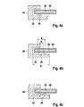
- wiper blade 10 has a strip-like elongated, resilient support member 12 ( FIGS. 1 and 2 ), at the lower, the disk facing, concave hinge side 13, an elongated, rubber-elastic wiper strip 14 is secured longitudinal axis parallel.
- convex hinge side 11 of the spring element to be designated as a support member 12 convex hinge side 11 of the spring element to be designated as a support member 12 a wiper blade-side connecting device 15 is arranged in the central portion, with the help of the wiper blade 10 articulated with a in FIG. 1 dash-dotted lines indicated wiper arm 16 can be releasably connected.
- oscillating driven wiper arm 16 is loaded in the direction of an arrow 24 to be wiped disc - for example, the windshield of a motor vehicle - whose surface in FIG. 1 is indicated by a dashed line 22. Since the line 22 is intended to represent the strongest curvature of the disk surface, it is clearly evident that the curvature of the still unloaded wiper blade resting against the disk with its two ends is greater than the maximum disk curvature (FIG. FIG. 1 ). Under the contact pressure (arrow 24), the wiper blade 10 with its wiper lip 26 lays against the disk surface 22 over its entire length. In this case, a stress builds up in the made of metal, resilient support member 12, which ensures proper installation of the wiper strip 14 and the wiper lip 26 over its entire length on the disk surface 22 and for a uniform distribution of the contact pressure (arrow 24).
- Fig. 2 is the connection device 15 shown in section. It has a base body 30 which has a bolt receptacle 32 (FIG. FIG. 1 ), which in Fig. 2 represented by its axis 34. On the main body 30, two opposite legs 36 are formed with a cross-sectionally U-shaped shape, the U-openings facing each other. This creates a cavity in which two spring rails 38 of the support member 12 are mounted, which in turn receive the wiper strip 14 between them.
- a bolt receptacle 32 FIG. FIG. 1
- two opposite legs 36 are formed with a cross-sectionally U-shaped shape, the U-openings facing each other. This creates a cavity in which two spring rails 38 of the support member 12 are mounted, which in turn receive the wiper strip 14 between them.
- the legs 36 are strip-shaped in the exemplary embodiment and extend over the entire length of the connecting device 15 they have with the base 30 connected upper strips 40, the main body 30 opposite and light 42 and the upper strips 40 with the lower strips 42 connecting webs 44.
- the legs 36 may also be formed collar-like and extend only partially along the connecting device.
- Fig. 3 is partially a leg 36 in the direction of the line III in Fig. 2 shown, wherein the welding between connection device 15 and support member 12 has not yet taken place and therefore Energytechnischmaschiner 46 can be seen.
- the Energytechnischmaschiner 46 are arranged on the lower bar 42 so that they point in the direction of their opposite spring rail 38.
- seven energy direction indicators 46 are arranged uniformly over the length of the lower strip 42.
- both the individual Energyschutterr 46 and the sum but Energyschitzr 46 in their area are small compared to the surface of the lower bar 42. This also applies to the overlap region between the lower bar 42 and the spring rail 38 opposite it.
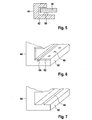
- the Energyschticianr 46 is approximately square in its base 48 and has a pyramidal elevation 50, as well as in Fig. 4a you can see. Each side of the base is about 1 mm, the height of the pyramid about 0.5 mm.
- Fig. 4b a truncated pyramidal embodiment is shown in which the width b of the small area is small compared to the width B of the base area, which in turn is small relative to the width B * of the bar 42 Fig. 4c
- the energy directors 42 may also be arranged in pairs next to each other. In extreme cases, a plurality of energy directors are arranged, which lead to a structuring of the surface.
- the survey 50 may also be convex, in particular semi-circular shape.
- the first contact between the Energyschurgir 46 and the spring rails 38 may thus be considered as a point-like contact or at least a contact with a small area.
- the distance 52 between two Energy therapiesticianr 46 is approximately three times as large as the side lengths 47, 49 of the base 48 and is therefore in the embodiment about 3 mm.
- the size and spacing of the energy directors 46 depend on the welding energy to be injected, which in turn is the higher the shorter the welding time available.
- the Energy directing device 46 may have a triangular shape.
- the Energy directing device 46 can have a triangular shape.
- the Energy directing device 46 can have a triangular shape.
- the Energy directing device 46 can have a triangular shape.
- the Energy directing device 46 can have a triangular shape.
- the Energy directing device 46 can have a triangular shape.
- the Energy directing device 46 can have a triangular shape.
- the Energy directing device 46 can have a triangular shape.
- the Energy directing device 46 can have a triangular shape.
- the Energy directing device 46 can have a triangular shape.
- the Energy directing device 46 can have a triangular shape.
- the Energy directing device 46 can have a triangular shape.
- the Energy directing device 46 can have a triangular shape.
- the Energy directing device 46 can have a triangular shape.
- the Energy directing device 46 can have a triangular shape.
- connection device 15 lies with its two lower strips 42 on an anvil 54 while the welding energy in the form of ultrasound is coupled from above.
- the main body 30 and the upper strips 40 recesses 58 extend through the horns 60 to the upper sides of the spring rails 38 and couple their ultrasonic energy in the spring rails.
- the ultrasonic waves pass through the usually held in metal spring rails 38 and reach on the underside of the tips of the Energyraumtechnikmaschiner 46. From there, the spot-like generated heat is introduced into the lower bar 42 and distributed.
- At least one energy direction indicator 46 lies directly below each recess 48 and thus directly under the sonotrode 60. Proceeding from these exposed energy direction indicators 46, a cascade-shaped propagation of the melt flow along the further energy direction indicators 46 on the lower strip 42 results.
- melt trough 64 may be provided, as in a variant in FIG Fig. 6 is shown.
- This melt trough 64 prevents excessive flow of melt flow toward webs 44 and improves flow along lower ledge 42.
- the height of the energy directors 46 should be in a range between 30% in 80% of the thickness to weld the spring rail 38 to move and will be in rails offer from 0.8 mm to 1 mm, preferably 0.5 mm to choose.
- the legs 36 surround the spring rails 38 of the support member 12 with play, so that the spring rails 38 are easily inserted into the legs 36. If, however, as described above, a squeezing seam is used, insertion is made more difficult. Relief brings an insertion bevel 62 in the region of the legs 36. The joining direction of the spring rails 38 in the legs 36 is then along the arrow 66th
- the connecting device 15 is made of a thermoplastic material and preferably produced as an injection molded part.
- the spring rails 38 are usually made of steel and can, as in Fig. 4 is indicated, have a sheath 68.
- This jacket 68 serves to protect the spring rail 38 and the better welding behavior between spring rail 38 and lower bar 42.
- the jacket 68 may also consist of a thermoplastic material.
- the spring rails 38 are first inserted into the legs 36 of the connecting device 15 and fixed in the position to be welded on an anvil 54 of an ultrasonic welding system. Then four sonotrodes 60 are retracted into the four recesses 58 until they rest on top of the spring rails 38. Under pressure of the sonotrodes 60 on the spring rails 38, the ultrasonic energy is coupled into the spring rail 38 a. The sound waves pass through the spring rail 38, hit the tips of the Energyschurgir 46 and start to melt them. From there, the plastic of the lower strips 42 heats up and forms a melt. The melt flow extends from the Energyschtechnikr 46 and promoted by the mandated pressure evenly over the spring rail 38 facing surface of the lower bar 42 and can be bundled using a melt trough 64.
- connection device 15 The supply of the ultrasonic energy is stopped and as soon as the curing of the melt flow begins, the pressure of the sonotrodes 60 on the spring rails 38 is reduced and the sonotrodes 60 from the recesses 58 moved out.
- the spring rails 38 and thus the support member 12 are fixedly connected to connection device 15 and it can be further elements such as the wiper strip 14 and optionally spoilers and end caps are added.
Landscapes
- Engineering & Computer Science (AREA)
- Mechanical Engineering (AREA)
- Lining Or Joining Of Plastics Or The Like (AREA)
- Surface Treatment Of Glass (AREA)
- Springs (AREA)
- Motor Or Generator Frames (AREA)
- Apparatus For Disinfection Or Sterilisation (AREA)
Priority Applications (1)
| Application Number | Priority Date | Filing Date | Title |
|---|---|---|---|
| PL11702966T PL2534017T3 (pl) | 2010-02-12 | 2011-02-01 | Pióro wycieraczki, zwłaszcza do szyb pojazdów mechanicznych, a także sposób produkcji pióra wycieraczki |
Applications Claiming Priority (2)
| Application Number | Priority Date | Filing Date | Title |
|---|---|---|---|
| DE102010001900A DE102010001900A1 (de) | 2010-02-12 | 2010-02-12 | Wischblatt, insbesondere für Scheiben von Kraftfahrzeugen, sowie Verfahren zum Herstellen eines Wischblatts |
| PCT/EP2011/051377 WO2011098372A1 (de) | 2010-02-12 | 2011-02-01 | Wischblatt, insbesondere für scheiben von kraftfahrzeugen, sowie verfahren zum herstellen eines wischblatts |
Publications (2)
| Publication Number | Publication Date |
|---|---|
| EP2534017A1 EP2534017A1 (de) | 2012-12-19 |
| EP2534017B1 true EP2534017B1 (de) | 2015-01-14 |
Family
ID=43743703
Family Applications (1)
| Application Number | Title | Priority Date | Filing Date |
|---|---|---|---|
| EP11702966.0A Active EP2534017B1 (de) | 2010-02-12 | 2011-02-01 | Wischblatt, insbesondere für scheiben von kraftfahrzeugen, sowie verfahren zum herstellen eines wischblatts |
Country Status (12)
| Country | Link |
|---|---|
| US (1) | US20120311809A1 (pl) |
| EP (1) | EP2534017B1 (pl) |
| JP (1) | JP5665883B2 (pl) |
| KR (1) | KR101404602B1 (pl) |
| CN (1) | CN102741099B (pl) |
| BR (1) | BR112012019831A2 (pl) |
| DE (1) | DE102010001900A1 (pl) |
| ES (1) | ES2528442T3 (pl) |
| IN (1) | IN2012DN04865A (pl) |
| PL (1) | PL2534017T3 (pl) |
| RU (1) | RU2555249C2 (pl) |
| WO (1) | WO2011098372A1 (pl) |
Families Citing this family (11)
| Publication number | Priority date | Publication date | Assignee | Title |
|---|---|---|---|---|
| DE102009002411A1 (de) * | 2009-04-16 | 2010-10-21 | Robert Bosch Gmbh | Wischblatt für einen Scheibenwischer |
| DE102010028102A1 (de) * | 2010-04-22 | 2011-10-27 | Robert Bosch Gmbh | Wischblatt für einen Scheibenwischer |
| DE102011004629A1 (de) * | 2011-02-24 | 2012-08-30 | Robert Bosch Gmbh | Wischblatt zum Reinigen von Scheiben insbesondere von Kraftfahrzeugen |
| DE102011090099A1 (de) * | 2011-12-29 | 2013-07-04 | Robert Bosch Gmbh | Wischblattadaptereinheit |
| JP2015003721A (ja) * | 2013-06-21 | 2015-01-08 | ケーシーダブリュー コーポレーション | ワイパーブレード |
| KR20160082517A (ko) * | 2013-11-06 | 2016-07-08 | 페더럴-모걸 모터파츠 코오포레이숀 | 리어 윈드스크린 와이퍼 디바이스 |
| WO2018219426A1 (en) * | 2017-05-29 | 2018-12-06 | Federal-Mogul S.A. | Windscreen wiper device |
| KR101978229B1 (ko) | 2019-03-11 | 2019-05-14 | 박종렬 | 슬릿가공장치 및 이를 이용한 슬릿가공방법 |
| KR101978230B1 (ko) | 2019-03-12 | 2019-05-14 | 박종렬 | 슬릿가공장치 및 이를 이용한 슬릿가공방법 |
| CN117841910B (zh) * | 2022-09-30 | 2025-11-11 | 厦门富可汽车配件有限公司 | 雨刷及用于实现支承元件与连接装置固接的加工方法 |
| CN115635945A (zh) * | 2022-09-30 | 2023-01-24 | 厦门富可汽车配件有限公司 | 雨刷及用于实现支承元件与连接装置固接的加工方法 |
Family Cites Families (16)
| Publication number | Priority date | Publication date | Assignee | Title |
|---|---|---|---|---|
| GB8726140D0 (en) * | 1987-11-07 | 1987-12-09 | Wright C W | Wiper blades |
| JP2607908B2 (ja) * | 1988-03-28 | 1997-05-07 | イズミ工業株式会社 | 小物物品の合成樹脂製品への結合具 |
| KR100616259B1 (ko) * | 1997-05-02 | 2006-12-22 | 로베르트 보쉬 게엠베하 | 와이퍼블레이드 |
| DE19718490A1 (de) | 1997-05-02 | 1998-11-05 | Bosch Gmbh Robert | Wischblatt für Scheiben von Kraftfahrzeugen |
| WO2000021811A1 (en) * | 1998-10-12 | 2000-04-20 | Trico Products Corporation | A windscreen wiper |
| EP1332075B1 (de) * | 2000-10-28 | 2004-12-15 | Robert Bosch Gmbh | Vorrichtung zum lösbaren, gelenkigen verbinden eines wischblatts zum reinigen von scheiben mit einem wischerarm |
| DE10113657A1 (de) | 2001-03-21 | 2002-09-26 | Bosch Gmbh Robert | Wischblatt zum Reinigen von Scheiben, insbesondere von Kraftfahrzeugen und Verfahren zum Herstellen des Wischblatts |
| DE10157130A1 (de) * | 2001-11-21 | 2003-06-05 | Bosch Gmbh Robert | Wischarm mit einem gelenkig verbundenen Wischblatt |
| EP1494903B1 (de) * | 2002-04-04 | 2008-09-17 | Robert Bosch Gmbh | Wischebel mit einem angetriebenen wischerarm und einem an diesem angelenkten wischblatt zum reinigen von scheiben insbesondere von kraftfahrzeugen |
| ES2267933T3 (es) * | 2002-05-03 | 2007-03-16 | Federal-Mogul S.A. | Dispositivo limpiaparabirsas. |
| DE20220355U1 (de) | 2002-11-15 | 2004-04-01 | Robert Bosch Gmbh | Wischblatt |
| EP1745997B1 (en) * | 2005-07-19 | 2008-12-17 | Federal-Mogul S.A. | Windscreen wiper device |
| JP2007038422A (ja) * | 2005-07-29 | 2007-02-15 | Kasai Kogyo Co Ltd | 樹脂部品の超音波溶着方法 |
| US7523522B2 (en) * | 2006-09-22 | 2009-04-28 | Federal Mogul World Wide, Inc | Two-piece connector for flat blade windshield wiper |
| DE102007012700A1 (de) * | 2007-03-16 | 2008-09-18 | Robert Bosch Gmbh | Wischblatt |
| US8042218B2 (en) * | 2007-04-05 | 2011-10-25 | Trico Products Corporation | Wiper assembly having side-saddle coupler |
-
2010
- 2010-02-12 DE DE102010001900A patent/DE102010001900A1/de not_active Withdrawn
-
2011
- 2011-02-01 WO PCT/EP2011/051377 patent/WO2011098372A1/de not_active Ceased
- 2011-02-01 KR KR1020127021069A patent/KR101404602B1/ko not_active Expired - Fee Related
- 2011-02-01 RU RU2012138893/11A patent/RU2555249C2/ru not_active IP Right Cessation
- 2011-02-01 ES ES11702966.0T patent/ES2528442T3/es active Active
- 2011-02-01 BR BR112012019831A patent/BR112012019831A2/pt active Search and Examination
- 2011-02-01 JP JP2012552336A patent/JP5665883B2/ja active Active
- 2011-02-01 EP EP11702966.0A patent/EP2534017B1/de active Active
- 2011-02-01 US US13/578,602 patent/US20120311809A1/en not_active Abandoned
- 2011-02-01 PL PL11702966T patent/PL2534017T3/pl unknown
- 2011-02-01 CN CN201180009182.3A patent/CN102741099B/zh active Active
- 2011-02-01 IN IN4865DEN2012 patent/IN2012DN04865A/en unknown
Also Published As
| Publication number | Publication date |
|---|---|
| JP5665883B2 (ja) | 2015-02-04 |
| CN102741099A (zh) | 2012-10-17 |
| KR20120115388A (ko) | 2012-10-17 |
| JP2013519559A (ja) | 2013-05-30 |
| WO2011098372A1 (de) | 2011-08-18 |
| KR101404602B1 (ko) | 2014-06-10 |
| EP2534017A1 (de) | 2012-12-19 |
| PL2534017T3 (pl) | 2015-06-30 |
| BR112012019831A2 (pt) | 2016-05-17 |
| DE102010001900A1 (de) | 2011-08-18 |
| RU2012138893A (ru) | 2014-03-20 |
| US20120311809A1 (en) | 2012-12-13 |
| IN2012DN04865A (pl) | 2015-09-25 |
| RU2555249C2 (ru) | 2015-07-10 |
| ES2528442T3 (es) | 2015-02-10 |
| CN102741099B (zh) | 2015-11-25 |
Similar Documents
| Publication | Publication Date | Title |
|---|---|---|
| EP2534017B1 (de) | Wischblatt, insbesondere für scheiben von kraftfahrzeugen, sowie verfahren zum herstellen eines wischblatts | |
| EP2560848B1 (de) | Wischblatt für einen scheibenwischer | |
| EP1732792B1 (de) | Wischblatt | |
| EP1597121B1 (de) | Verfahren zum herstellen eines wischblatts sowie vorrichtung zur durchführung des verfahrens und danach hergestelltes wischblatt | |
| EP1853404B1 (de) | Ultraschallschweissvorrichtung mit einen verdichtungsraum begrenzenden gegenüberliegenden schweiss- und seitenfläche sowie ein werkzeug für eine solche ultraschallschweissvorrichtung | |
| DE19718490A1 (de) | Wischblatt für Scheiben von Kraftfahrzeugen | |
| DE10335396A1 (de) | Verfahren zum Herstellen eines Wischblatts sowie Vorrichtung zur Durchführung des Verfahrens und danach hergestelltes Wischblatt | |
| EP2984710A1 (de) | Verfahren zum verbinden eines rohrkabelschuhs mit einer aus aluminium hergestellten litze | |
| DE102007012700A1 (de) | Wischblatt | |
| WO2012113709A1 (de) | Wischblatt sowie ein verfahren zum herstellen eines wischblatts | |
| EP2797784B1 (de) | Wischblattadaptereinheit | |
| WO2012113710A1 (de) | Wischblatt zum reinigen von scheiben, insbesondere von kraftfahrzeugen | |
| DE102016204483B4 (de) | Befestigungselement mit mindestens einem Clip zur Herstellung einer Verbindung mit einem korrespondierenden Ansteckelement und Anordnung eines Befestigungselements an einem Ansteckelement | |
| EP3034276A1 (de) | Bauteil mit stoffschlüssiger Verbindung und ein Fügeverfahren | |
| EP2678198B1 (de) | Verfahren zum herstellen von wischblättern sowie ein wischblatt zum wischen von scheiben | |
| EP2020285A2 (de) | Bauteilanordnung | |
| WO2012171698A1 (de) | Wischblatt zum reinigen von scheiben insbesondere von kraftfahrzeugen | |
| EP2720915B1 (de) | Wischblatt zum reinigen von scheiben insbesondere von kraftfahrzeugen | |
| WO2012113715A1 (de) | Wischblatt zum reinigen von scheiben, insbesondere von kraftfahrzeugen | |
| EP1775172B1 (de) | Vorrichtung zur Aufpralldämpfung | |
| WO2015032573A1 (de) | Vorspannungsvorrichtung für eine scheibenwischvorrichtung | |
| DE202024104635U1 (de) | Wischblatt, insbesondere für ein Kraftfahrzeug | |
| DE102013203686A1 (de) | Wischblatt zum Reinigen von Scheiben insbesondere von Kraftfahrzeugen | |
| DE1480040C (de) | Scheibenwischer für Fahrzeuge |
Legal Events
| Date | Code | Title | Description |
|---|---|---|---|
| PUAI | Public reference made under article 153(3) epc to a published international application that has entered the european phase |
Free format text: ORIGINAL CODE: 0009012 |
|
| 17P | Request for examination filed |
Effective date: 20120912 |
|
| AK | Designated contracting states |
Kind code of ref document: A1 Designated state(s): AL AT BE BG CH CY CZ DE DK EE ES FI FR GB GR HR HU IE IS IT LI LT LU LV MC MK MT NL NO PL PT RO RS SE SI SK SM TR |
|
| DAX | Request for extension of the european patent (deleted) | ||
| GRAP | Despatch of communication of intention to grant a patent |
Free format text: ORIGINAL CODE: EPIDOSNIGR1 |
|
| INTG | Intention to grant announced |
Effective date: 20141014 |
|
| GRAS | Grant fee paid |
Free format text: ORIGINAL CODE: EPIDOSNIGR3 |
|
| GRAA | (expected) grant |
Free format text: ORIGINAL CODE: 0009210 |
|
| AK | Designated contracting states |
Kind code of ref document: B1 Designated state(s): AL AT BE BG CH CY CZ DE DK EE ES FI FR GB GR HR HU IE IS IT LI LT LU LV MC MK MT NL NO PL PT RO RS SE SI SK SM TR |
|
| REG | Reference to a national code |
Ref country code: GB Ref legal event code: FG4D Free format text: NOT ENGLISH |
|
| REG | Reference to a national code |
Ref country code: CH Ref legal event code: EP |
|
| REG | Reference to a national code |
Ref country code: ES Ref legal event code: FG2A Ref document number: 2528442 Country of ref document: ES Kind code of ref document: T3 Effective date: 20150210 |
|
| REG | Reference to a national code |
Ref country code: IE Ref legal event code: FG4D Free format text: LANGUAGE OF EP DOCUMENT: GERMAN |
|
| REG | Reference to a national code |
Ref country code: AT Ref legal event code: REF Ref document number: 706851 Country of ref document: AT Kind code of ref document: T Effective date: 20150215 |
|
| REG | Reference to a national code |
Ref country code: DE Ref legal event code: R096 Ref document number: 502011005638 Country of ref document: DE Effective date: 20150226 |
|
| REG | Reference to a national code |
Ref country code: SE Ref legal event code: TRGR |
|
| REG | Reference to a national code |
Ref country code: LT Ref legal event code: MG4D |
|
| REG | Reference to a national code |
Ref country code: PL Ref legal event code: T3 |
|
| PG25 | Lapsed in a contracting state [announced via postgrant information from national office to epo] |
Ref country code: HR Free format text: LAPSE BECAUSE OF FAILURE TO SUBMIT A TRANSLATION OF THE DESCRIPTION OR TO PAY THE FEE WITHIN THE PRESCRIBED TIME-LIMIT Effective date: 20150114 Ref country code: LT Free format text: LAPSE BECAUSE OF FAILURE TO SUBMIT A TRANSLATION OF THE DESCRIPTION OR TO PAY THE FEE WITHIN THE PRESCRIBED TIME-LIMIT Effective date: 20150114 Ref country code: BG Free format text: LAPSE BECAUSE OF FAILURE TO SUBMIT A TRANSLATION OF THE DESCRIPTION OR TO PAY THE FEE WITHIN THE PRESCRIBED TIME-LIMIT Effective date: 20150414 Ref country code: NO Free format text: LAPSE BECAUSE OF FAILURE TO SUBMIT A TRANSLATION OF THE DESCRIPTION OR TO PAY THE FEE WITHIN THE PRESCRIBED TIME-LIMIT Effective date: 20150414 Ref country code: FI Free format text: LAPSE BECAUSE OF FAILURE TO SUBMIT A TRANSLATION OF THE DESCRIPTION OR TO PAY THE FEE WITHIN THE PRESCRIBED TIME-LIMIT Effective date: 20150114 |
|
| PG25 | Lapsed in a contracting state [announced via postgrant information from national office to epo] |
Ref country code: LV Free format text: LAPSE BECAUSE OF FAILURE TO SUBMIT A TRANSLATION OF THE DESCRIPTION OR TO PAY THE FEE WITHIN THE PRESCRIBED TIME-LIMIT Effective date: 20150114 Ref country code: IS Free format text: LAPSE BECAUSE OF FAILURE TO SUBMIT A TRANSLATION OF THE DESCRIPTION OR TO PAY THE FEE WITHIN THE PRESCRIBED TIME-LIMIT Effective date: 20150514 Ref country code: GR Free format text: LAPSE BECAUSE OF FAILURE TO SUBMIT A TRANSLATION OF THE DESCRIPTION OR TO PAY THE FEE WITHIN THE PRESCRIBED TIME-LIMIT Effective date: 20150415 Ref country code: RS Free format text: LAPSE BECAUSE OF FAILURE TO SUBMIT A TRANSLATION OF THE DESCRIPTION OR TO PAY THE FEE WITHIN THE PRESCRIBED TIME-LIMIT Effective date: 20150114 |
|
| REG | Reference to a national code |
Ref country code: HU Ref legal event code: AG4A Ref document number: E024001 Country of ref document: HU |
|
| REG | Reference to a national code |
Ref country code: CH Ref legal event code: PL |
|
| REG | Reference to a national code |
Ref country code: DE Ref legal event code: R097 Ref document number: 502011005638 Country of ref document: DE |
|
| PG25 | Lapsed in a contracting state [announced via postgrant information from national office to epo] |
Ref country code: EE Free format text: LAPSE BECAUSE OF FAILURE TO SUBMIT A TRANSLATION OF THE DESCRIPTION OR TO PAY THE FEE WITHIN THE PRESCRIBED TIME-LIMIT Effective date: 20150114 Ref country code: RO Free format text: LAPSE BECAUSE OF FAILURE TO SUBMIT A TRANSLATION OF THE DESCRIPTION OR TO PAY THE FEE WITHIN THE PRESCRIBED TIME-LIMIT Effective date: 20150114 Ref country code: DK Free format text: LAPSE BECAUSE OF FAILURE TO SUBMIT A TRANSLATION OF THE DESCRIPTION OR TO PAY THE FEE WITHIN THE PRESCRIBED TIME-LIMIT Effective date: 20150114 Ref country code: SK Free format text: LAPSE BECAUSE OF FAILURE TO SUBMIT A TRANSLATION OF THE DESCRIPTION OR TO PAY THE FEE WITHIN THE PRESCRIBED TIME-LIMIT Effective date: 20150114 Ref country code: CH Free format text: LAPSE BECAUSE OF NON-PAYMENT OF DUE FEES Effective date: 20150228 Ref country code: LI Free format text: LAPSE BECAUSE OF NON-PAYMENT OF DUE FEES Effective date: 20150228 Ref country code: MC Free format text: LAPSE BECAUSE OF FAILURE TO SUBMIT A TRANSLATION OF THE DESCRIPTION OR TO PAY THE FEE WITHIN THE PRESCRIBED TIME-LIMIT Effective date: 20150114 Ref country code: CZ Free format text: LAPSE BECAUSE OF FAILURE TO SUBMIT A TRANSLATION OF THE DESCRIPTION OR TO PAY THE FEE WITHIN THE PRESCRIBED TIME-LIMIT Effective date: 20150114 |
|
| REG | Reference to a national code |
Ref country code: IE Ref legal event code: MM4A |
|
| PLBE | No opposition filed within time limit |
Free format text: ORIGINAL CODE: 0009261 |
|
| STAA | Information on the status of an ep patent application or granted ep patent |
Free format text: STATUS: NO OPPOSITION FILED WITHIN TIME LIMIT |
|
| 26N | No opposition filed |
Effective date: 20151015 |
|
| PG25 | Lapsed in a contracting state [announced via postgrant information from national office to epo] |
Ref country code: IE Free format text: LAPSE BECAUSE OF NON-PAYMENT OF DUE FEES Effective date: 20150201 |
|
| REG | Reference to a national code |
Ref country code: FR Ref legal event code: PLFP Year of fee payment: 6 |
|
| PG25 | Lapsed in a contracting state [announced via postgrant information from national office to epo] |
Ref country code: SI Free format text: LAPSE BECAUSE OF FAILURE TO SUBMIT A TRANSLATION OF THE DESCRIPTION OR TO PAY THE FEE WITHIN THE PRESCRIBED TIME-LIMIT Effective date: 20150114 |
|
| PG25 | Lapsed in a contracting state [announced via postgrant information from national office to epo] |
Ref country code: MT Free format text: LAPSE BECAUSE OF FAILURE TO SUBMIT A TRANSLATION OF THE DESCRIPTION OR TO PAY THE FEE WITHIN THE PRESCRIBED TIME-LIMIT Effective date: 20150114 |
|
| REG | Reference to a national code |
Ref country code: FR Ref legal event code: PLFP Year of fee payment: 7 |
|
| REG | Reference to a national code |
Ref country code: AT Ref legal event code: MM01 Ref document number: 706851 Country of ref document: AT Kind code of ref document: T Effective date: 20160201 |
|
| PG25 | Lapsed in a contracting state [announced via postgrant information from national office to epo] |
Ref country code: AT Free format text: LAPSE BECAUSE OF NON-PAYMENT OF DUE FEES Effective date: 20160201 Ref country code: SM Free format text: LAPSE BECAUSE OF FAILURE TO SUBMIT A TRANSLATION OF THE DESCRIPTION OR TO PAY THE FEE WITHIN THE PRESCRIBED TIME-LIMIT Effective date: 20150114 |
|
| PG25 | Lapsed in a contracting state [announced via postgrant information from national office to epo] |
Ref country code: CY Free format text: LAPSE BECAUSE OF FAILURE TO SUBMIT A TRANSLATION OF THE DESCRIPTION OR TO PAY THE FEE WITHIN THE PRESCRIBED TIME-LIMIT Effective date: 20150114 |
|
| PG25 | Lapsed in a contracting state [announced via postgrant information from national office to epo] |
Ref country code: PT Free format text: LAPSE BECAUSE OF FAILURE TO SUBMIT A TRANSLATION OF THE DESCRIPTION OR TO PAY THE FEE WITHIN THE PRESCRIBED TIME-LIMIT Effective date: 20150514 |
|
| PG25 | Lapsed in a contracting state [announced via postgrant information from national office to epo] |
Ref country code: TR Free format text: LAPSE BECAUSE OF FAILURE TO SUBMIT A TRANSLATION OF THE DESCRIPTION OR TO PAY THE FEE WITHIN THE PRESCRIBED TIME-LIMIT Effective date: 20150114 |
|
| PG25 | Lapsed in a contracting state [announced via postgrant information from national office to epo] |
Ref country code: LU Free format text: LAPSE BECAUSE OF NON-PAYMENT OF DUE FEES Effective date: 20150201 |
|
| REG | Reference to a national code |
Ref country code: FR Ref legal event code: PLFP Year of fee payment: 8 |
|
| PG25 | Lapsed in a contracting state [announced via postgrant information from national office to epo] |
Ref country code: MK Free format text: LAPSE BECAUSE OF FAILURE TO SUBMIT A TRANSLATION OF THE DESCRIPTION OR TO PAY THE FEE WITHIN THE PRESCRIBED TIME-LIMIT Effective date: 20150114 |
|
| PG25 | Lapsed in a contracting state [announced via postgrant information from national office to epo] |
Ref country code: AL Free format text: LAPSE BECAUSE OF FAILURE TO SUBMIT A TRANSLATION OF THE DESCRIPTION OR TO PAY THE FEE WITHIN THE PRESCRIBED TIME-LIMIT Effective date: 20150114 |
|
| PGFP | Annual fee paid to national office [announced via postgrant information from national office to epo] |
Ref country code: HU Payment date: 20200122 Year of fee payment: 10 Ref country code: IT Payment date: 20200221 Year of fee payment: 10 Ref country code: ES Payment date: 20200320 Year of fee payment: 10 Ref country code: GB Payment date: 20200225 Year of fee payment: 10 Ref country code: NL Payment date: 20200220 Year of fee payment: 10 Ref country code: SE Payment date: 20200224 Year of fee payment: 10 Ref country code: PL Payment date: 20200122 Year of fee payment: 10 |
|
| REG | Reference to a national code |
Ref country code: SE Ref legal event code: EUG |
|
| GBPC | Gb: european patent ceased through non-payment of renewal fee |
Effective date: 20210201 |
|
| PG25 | Lapsed in a contracting state [announced via postgrant information from national office to epo] |
Ref country code: HU Free format text: LAPSE BECAUSE OF NON-PAYMENT OF DUE FEES Effective date: 20210202 |
|
| PG25 | Lapsed in a contracting state [announced via postgrant information from national office to epo] |
Ref country code: SE Free format text: LAPSE BECAUSE OF NON-PAYMENT OF DUE FEES Effective date: 20210202 |
|
| REG | Reference to a national code |
Ref country code: NL Ref legal event code: MM Effective date: 20210301 |
|
| PG25 | Lapsed in a contracting state [announced via postgrant information from national office to epo] |
Ref country code: NL Free format text: LAPSE BECAUSE OF NON-PAYMENT OF DUE FEES Effective date: 20210301 |
|
| PG25 | Lapsed in a contracting state [announced via postgrant information from national office to epo] |
Ref country code: GB Free format text: LAPSE BECAUSE OF NON-PAYMENT OF DUE FEES Effective date: 20210201 |
|
| PG25 | Lapsed in a contracting state [announced via postgrant information from national office to epo] |
Ref country code: IT Free format text: LAPSE BECAUSE OF NON-PAYMENT OF DUE FEES Effective date: 20210201 |
|
| REG | Reference to a national code |
Ref country code: ES Ref legal event code: FD2A Effective date: 20220510 |
|
| PG25 | Lapsed in a contracting state [announced via postgrant information from national office to epo] |
Ref country code: ES Free format text: LAPSE BECAUSE OF NON-PAYMENT OF DUE FEES Effective date: 20210202 |
|
| PG25 | Lapsed in a contracting state [announced via postgrant information from national office to epo] |
Ref country code: PL Free format text: LAPSE BECAUSE OF NON-PAYMENT OF DUE FEES Effective date: 20210201 |
|
| PGFP | Annual fee paid to national office [announced via postgrant information from national office to epo] |
Ref country code: BE Payment date: 20250218 Year of fee payment: 15 |
|
| PGFP | Annual fee paid to national office [announced via postgrant information from national office to epo] |
Ref country code: FR Payment date: 20250220 Year of fee payment: 15 |
|
| PGFP | Annual fee paid to national office [announced via postgrant information from national office to epo] |
Ref country code: DE Payment date: 20250422 Year of fee payment: 15 |