EP2532798A1 - Lost formwork for concrete wall, in particular of a building - Google Patents
Lost formwork for concrete wall, in particular of a building Download PDFInfo
- Publication number
- EP2532798A1 EP2532798A1 EP12170806A EP12170806A EP2532798A1 EP 2532798 A1 EP2532798 A1 EP 2532798A1 EP 12170806 A EP12170806 A EP 12170806A EP 12170806 A EP12170806 A EP 12170806A EP 2532798 A1 EP2532798 A1 EP 2532798A1
- Authority
- EP
- European Patent Office
- Prior art keywords
- spacer
- insulating material
- blocks
- lost formwork
- spar
- Prior art date
- Legal status (The legal status is an assumption and is not a legal conclusion. Google has not performed a legal analysis and makes no representation as to the accuracy of the status listed.)
- Granted
Links
Images

Classifications
-
- E—FIXED CONSTRUCTIONS
- E04—BUILDING
- E04B—GENERAL BUILDING CONSTRUCTIONS; WALLS, e.g. PARTITIONS; ROOFS; FLOORS; CEILINGS; INSULATION OR OTHER PROTECTION OF BUILDINGS
- E04B2/00—Walls, e.g. partitions, for buildings; Wall construction with regard to insulation; Connections specially adapted to walls
- E04B2/84—Walls made by casting, pouring, or tamping in situ
- E04B2/86—Walls made by casting, pouring, or tamping in situ made in permanent forms
- E04B2/8652—Walls made by casting, pouring, or tamping in situ made in permanent forms with ties located in the joints of the forms
-
- E—FIXED CONSTRUCTIONS
- E04—BUILDING
- E04B—GENERAL BUILDING CONSTRUCTIONS; WALLS, e.g. PARTITIONS; ROOFS; FLOORS; CEILINGS; INSULATION OR OTHER PROTECTION OF BUILDINGS
- E04B2/00—Walls, e.g. partitions, for buildings; Wall construction with regard to insulation; Connections specially adapted to walls
- E04B2/84—Walls made by casting, pouring, or tamping in situ
- E04B2/86—Walls made by casting, pouring, or tamping in situ made in permanent forms
- E04B2/8658—Walls made by casting, pouring, or tamping in situ made in permanent forms using wire netting, a lattice or the like as form leaves
Definitions
- the present invention relates to a lost formwork for concrete wall, including a building.
- the wall with high inertia namely the concrete wall is the outer wall of the building, and the inner wall of the building is an insulating material.
- These traditional systems with simple insulation have the drawbacks of only limiting heat losses and depriving the concrete wall of the natural supply of heat (winter comfort) or freshness (summer comfort) that it could store and return.
- WO 2005/042864 describes a formwork for a reinforced concrete wall, comprising two series of parallel horizontal bars pivotally traversing vertical sections, the horizontal bars being connected, at the level of the vertical sections, by transverse connecting bars, themselves pivotally mounted on horizontal bars.
- Metal panels forming walls are attached to the outside vertical profiles. If this type of formwork has the advantage of being manufactured in the factory and moved in folded form, with the two formwork panels applied against each other, after pivoting of the transverse connecting bars, it has the disadvantage of be heavy to handle and lack modularity.
- the document FR 2 540 539 A1 discloses a lost formwork device which comprises in particular insulating form plates connected together by base spacers and horizontally and vertically positioned stiffening ladders, allowing the construction of thermally-wrapped clad walls.
- the thermal insulation can be of varying thickness.
- this double-insulated system has the same disadvantages as those described for a traditional system of interior insulation, namely not to take advantage of the high inertia of the concrete wall, and therefore the natural heat supply that she could store and return.
- the formwork allows a complete and simplified integration of the technical networks and reinforcements, as well as the facilitated realization of the ligature of the vertical links with the steels waiting wall foot, before the casting of the concrete.
- the present invention proposes a lost formwork for a concrete wall, in particular a building, which perfectly meets all the requirements described above.
- the spacers are advantageously made of a plastic material, such as polyethylene or polypropylene. They provide the connection between the blocks made of insulating material. In addition, they contribute to the mechanical strength of the blocks of insulating material between them and allow to maintain a constant spacing with the elements intended to form the inner wall of the building. The spacers also contribute to the proper positioning of reinforcement, horizontal and vertical steels.
- profiled bars forming vertical stiffeners are preferably made of galvanized steel. In addition to fixing the metal mesh (which is advantageously vertical) and they contribute to the assembly of the spacers, profiled bars also contribute to the rigidity of the formwork according to the invention.
- the building wall made from a lost formwork according to the invention makes it possible to take advantage of the thermal inertia of the concrete inner wall which stores the heat and restores it.
- the outer wall made of an insulating material cold entry is limited. Thus, there is a decrease in temperature variations within the building.
- the blocks of insulating material are expanded polystyrene blocks, preferably with a density of between 25 and 30 kg / m 3 .
- the blocks of insulating material have a generally parallelepipedal shape of 1.26m x 0.25m, and a thickness of 16 or 21 cm, so as to have a total thickness of 32 and 37 cm before inner cladding.
- the blocks are divided into 24 steps of 5.25 cm, materialized by a series of two parallel lines, allowing a precise cutting with the handsaw.
- the lost formwork according to the invention thus has a thickness of the insulating wall increased with respect to the known construction structures and described above.
- the formwork according to the invention is devoid of interior insulation, but it has an outer insulation of significant thickness which minimizes energy losses and promote thermal inertia.
- the blocks made of insulating material may have been subjected to a flame retardant coating for fire classification in category M1.
- Their faces can be smooth to receive RPE type coatings or grooves to receive lightened hydraulic plaster.
- the lost formwork according to the invention is designed so that the thickness of concrete is preferably 16 cm.
- the concrete that will be poured into the lost formwork according to the invention is in accordance with the referencing standard Concrete, namely the NF EN 206-1 standard. Concrete can also meet other characteristics chosen by the user that will be complementary to those subject to the aforementioned NF standard.
- the selected concrete will preferably have the following characteristics: B PS NF EN 206-1 XC1 (F) C25 / 30 Dmax 12 S3. This corresponds to a concrete that can be armed.
- the grid is a ribbed galvanized steel lattice, made in one piece by simultaneous cutting and drawing.
- the expanded metal is inherently indémaillable.
- the batten is positioned so that the grooves providing the rigidity are horizontal and oriented on the inner side of the lost formwork.
- the meshes advantageously have the following dimensions: 7 ⁇ 10 mm.
- the mesh retains the entirety of its structure and all its rigidity. In addition, it does not require flanging, reinforcement or peripheral welding.
- the mesh is sufficiently rigid to retain the concrete whose advantageous characteristics have been described above. It also allows, when pouring concrete, to reduce the pressure of excess water. Excess water is removed through the lath, which limits the phenomenon of concrete removal.
- the technical characteristics of the mesh can be chosen so that an interior finish of plaster or mineral coatings can be deposited on the inner wall of the building.
- the thermal resistance of a wall is equal to the sum of the thermal resistances of the elements that compose it.
- the thermal resistances of the interior and exterior coatings are negligible.
- the thermal resistance of the wall thus calculated is particularly high.
- each profiled bar comprises at least one clipping means coming to clip on the second fixing means of the spacer.
- each profiled bar is metallic and has tabs obtained by cutting, intended to achieve the fastenings to the grill after being folded.
- the spacer may further comprise at least one intermediate cross member parallel to the end crosspieces, this intermediate cross member forming one of the first means for fixing the spacer on the blocks of insulating material.
- This intermediate crosspiece contributes to the rigidity of the spacer, and therefore also to the formwork as a whole.
- the spacer may also comprise at least one intermediate spar, this intermediate spar forming one of the first means for fixing the spacer on the blocks of insulating material.
- a plurality of openings may be formed in the intermediate spar, these openings forming one of the first means for fixing the spacer on the blocks of insulating material.
- the spacer may comprise at least one means for attaching a sheath which is arranged on an end cross member and / or on an intermediate cross member between the blocks of insulating material and the inner spar.
- the transverse and longitudinal grooves that includes the block of insulating material to stabilize the spacer which is inserted between two blocks of insulating material assembled one on the other. In other words, they prevent the spacers from moving; which is not possible with such a formwork structure for concrete wall.
- these grooves in particular by their combination of longitudinal and transverse grooves, contribute to obtaining spacers perfectly aligned with each other.
- the concrete can be poured to a constant thickness.
- the inner spar may comprise at least one recess facing the inside of the formwork intended to allow the embedding of a profiled bar.
- the recess thus forms one of the second attachment means of which the spacer is equipped.
- the profile bar has, in cross section, a general shape of C, and each recess of an inner spar of a spacer has pins for clipping the edges of the profiled bar.
- Each recess and the lugs thus form one of the second fixing means of the spacer.
- Each recess may have a central stud on which can be screwed profiled bar.
- the central block thus also forms one of the second means for fixing the spacer.
- the lost formwork element according to the invention may comprise at least one vertical connection element between two superimposed spacers.
- the connecting element makes it possible to stiffen the formwork.
- the connecting element is constituted by a flap, an edge of which is provided with at least one hinge articulation means disposed on an end cross member of a first spacer between the blocks of insulating material and the inner spar, and the opposite edge is provided with at least one locking means on an end cross member of a second spacer.
- the connecting element consists of two parts. One edge of each of these two flaps is provided with at least one hinge hinge means which is arranged on each of the end cross members of a first spacer between the blocks of material insulation and inner spar. The opposite edges of each of these flaps are provided with at least one locking means on an end cross member of a second spacer.
- the flap is provided with at least one tongue which makes it possible to block the vertical movement of the horizontal steels.
- the lost formwork according to the invention can easily and quickly be assembled on site. Indeed, the implementation of the formwork according to the invention is simple. In addition, because of the technical characteristics of the elements of which formwork is formed, described above, the assembly of this lost formwork does not require lifting equipment. This is particularly interesting from an economic point of view.
- the lost formwork according to the invention is easily adjustable, thanks to the various elements that constitute it.
- the concrete can be poured. Because of the good positioning of the technical networks before pouring the concrete, this makes it possible to avoid bleeding.
- spacer 1 of generally rectangular shape which has an outer spar 12, an inner spar 11 and an intermediate spar 3 which are interconnected by two end cross members 13,14 and an intermediate cross member 2.
- the intermediate cross member 2 is equipped with a fastening means 9 of a sheath 20 (not shown in FIG. figure 1 ).
- the inner spar 11 has two recesses 38 which each have lugs 34 for clipping the edges of a profiled bar 22, and a central stud 41 located between the lugs 34 which allows the screwing of the pimpled bars 22 on the spacer 1.
- a plurality of openings 4 are formed in the intermediate spar 3.
- Pins 10 for the locations of horizontal steels 27 are arranged on the intermediate crosspiece 2, and a guide 23 for laying a block of insulating material 15 (not shown in FIG. figure 1 ).
- the connecting element 6 is constituted by a flap which is equipped with the spacer 1 and allows to assemble it to a spacer 1 (not shown on the figure 1 ) disposed below the spacer 1.
- An edge of the flap 6 is assembled on the end cross member 13 of the spacer 1 with a hinge hinge means (not visible on the figure 1 ).
- the opposite edge 30 of the flap 6 comprises hooks 7 which constitute locking means of the flap 6 on the spacer 1 not shown disposed below the spacer 1. The hooks 7 are snapped into the openings 5 of this spacer 1 from below, and this in a locked way.
- figure 3 represents in enlargement the locking of a flap 6 of a first spacer 1 on the openings 5 of a second spacer 1 below.
- the opposite edge 30 of the shutter 6 is provided with a tongue 39 which blocks the vertical movement of the horizontal steels 27 as is visible on the figure 5 .
- the flap 6 As shown on the figure 2 when the flap 6 is folded, it is inserted into the surface delimited by the end cross member 13, the intermediate cross member 2, the intermediate spar 3 and the inner spar 11.
- the spacers 1 equipped with flap 6 in the folded form take up no space and can be easily stored and transported to the site. On site, the spacers are easily assembled to each other by unfolding the flap 6 and snapping them to each other with the locking means described above.
- reinforcing blades 35 are shown which are inserted in the openings 8 formed, respectively, in the end cross member 13, the intermediate cross member 2 and the end cross member 14 of the spacer 1.
- the reinforcing blades 35 contribute to the rigidity of the lost formwork 29 at the junctions with the slabs.
- bosses 17 of the block of lower insulating material 15 are nested in the recesses of the block of upper insulating material 15.
- the profiled bars 22 represented on the figure 6 are metal and have a general shape of C. They have tabs 24 which were obtained by cutting.
- the metal mesh 26 has been fixed on the profiled bars 22 after the folding of these tongues 24.
- the profiled bars 22 serve as a mounting bracket for a plate 25 which, in turn, serves to fix electrical boxes (not shown on the figure 6 ).
- Angled profiles 40 are arranged along the entire length of the wall on the inner side. They are screwed on the profiled bars 22 and on the slab. These angled sections 40 make it possible to fix the grid 26 at the foot of the wall. In this way, the grid 26 is trapped between the profiled bars 22 and the angled profiles 40.
Abstract
Description
La présente invention concerne un coffrage perdu pour mur en béton, notamment d'un bâtiment.The present invention relates to a lost formwork for concrete wall, including a building.
A l'heure actuelle, la hausse des coûts de l'énergie représente une part importante des dépenses pour les foyers. La réglementation en matière d'environnement étant également de plus en plus exigeante, elle vise à court terme à réduire la dépense énergétique à 50 kWhep/m2.an, et à passer d'ici 2020 à des bâtiments à énergie positive (à savoir qu'ils produisent plus d'énergie qu'ils n'en consomment). C'est pourquoi, il devient indispensable de repenser les techniques actuelles de construction.At present, rising energy costs are a significant part of household spending. The environmental regulations also are increasingly demanding, it is short term to reduce the energy consumption to 50 kWhep / m 2 .an, and spend 2020 to positive energy buildings (ie they produce more energy than they consume). This is why it is essential to rethink current construction techniques.
La combinaison la plus efficace à ce jour est l'association de matériaux ayant à la fois :
- une inertie thermique élevée (autrement dit, la capacité d'un matériau à emmagasiner de la chaleur et à la restituer), et
- une faible conductivité thermique (à savoir la capacité à transmettre la chaleur).
- high thermal inertia (in other words, the ability of a material to store heat and restore it), and
- low thermal conductivity (ie the ability to transmit heat).
Les procédés de maçonnerie actuels de murs extérieurs de bâtiments intègrent souvent une simple, voire une double isolation extérieure et intérieure, d'épaisseurs comprises entre 5 et 10 cm chacune. L'isolation caractérise le fait qu'un matériau bloque les évolutions de températures, et ce sans stockage d'énergie. C'est pourquoi, l'isolation et l'inertie sont complémentaires, et l'emploi d'un isolant avec un matériau à forte inertie, tel que le béton, permet de valoriser cette propriété d'inertie.The current masonry processes of exterior walls of buildings often incorporate a simple or even double outer and inner insulation, thicknesses between 5 and 10 cm each. The insulation characterizes the fact that a material blocks the evolutions of temperatures, and this without energy storage. This is why insulation and inertia are complementary, and the use of an insulator with a material with high inertia, such as concrete, makes it possible to enhance this property of inertia.
Traditionnellement, dans les procédés de maçonnerie mettant en oeuvre une simple isolation, la paroi à forte inertie, à savoir la paroi en béton constitue la paroi extérieure du bâtiment, et la paroi intérieure du bâtiment est en un matériau isolant. Ces systèmes traditionnels à isolation simple présentent les inconvénients de ne faire que de limiter les pertes de chaleur et de priver la paroi béton de l'apport naturel de chaleur (confort d'hiver) ou de fraîcheur (confort d'été) qu'elle pourrait emmagasiner et restituer.Traditionally, in masonry processes using simple insulation, the wall with high inertia, namely the concrete wall is the outer wall of the building, and the inner wall of the building is an insulating material. These traditional systems with simple insulation have the drawbacks of only limiting heat losses and depriving the concrete wall of the natural supply of heat (winter comfort) or freshness (summer comfort) that it could store and return.
Le document
En ce qui concerne les procédés de maçonnerie mettant en oeuvre une double isolation extérieure et intérieure, le document
Ainsi, pour disposer d'une température intérieure régulière et confortable tout au long de la journée, et même de l'année, il convient de mettre au point un système de construction de murs extérieurs qui,
- d'une part tire profit de l'inertie d'un matériau à forte inertie, et ce en réalisant des murs dont la paroi en béton se trouve du côté intérieur du bâtiment, et
- d'autre part optimise une isolation uniquement du côté extérieur du bâtiment, de manière à diminuer les variations de températures au sein du bâtiment.
- on the one hand takes advantage of the inertia of a material with high inertia, and by making walls whose concrete wall is on the inside of the building, and
- on the other hand optimizes insulation only on the outside of the building, so as to reduce temperature variations within the building.
Outre les exigences thermiques précitées auxquelles doit se conformer un tel système de construction, la nécessité d'un assemblage facile des éléments constituant le mur extérieur du bâtiment est aussi primordiale. C'est pourquoi, il convient de mettre au point un coffrage pour mur en béton que l'on puisse assembler sur le chantier facilement, rapidement et économiquement dans le but de construire un mur.In addition to the aforementioned thermal requirements that such a construction system must meet, the need for easy assembly of the elements constituting the exterior wall of the building is also essential. Therefore, a concrete wall formwork must be developed that can be assembled on the jobsite easily, quickly and economically for the purpose of building a wall.
De plus, il est tout à fait avantageux que le coffrage permette une intégration complète et simplifiée des réseaux techniques et des armatures, ainsi que la réalisation facilitée de la ligature des chaînages verticaux avec les aciers en attente de pied de mur, avant le coulage du béton.In addition, it is quite advantageous that the formwork allows a complete and simplified integration of the technical networks and reinforcements, as well as the facilitated realization of the ligature of the vertical links with the steels waiting wall foot, before the casting of the concrete.
Enfin, un tel coffrage doit avoir une tenue suffisante pour pouvoir y couler le béton.Finally, such a formwork must have sufficient strength to be able to pour the concrete.
La présente invention propose un coffrage perdu pour mur en béton, notamment d'un bâtiment, qui répond parfaitement à l'ensemble des exigences décrites ci-dessus.The present invention proposes a lost formwork for a concrete wall, in particular a building, which perfectly meets all the requirements described above.
L'invention a pour objet un coffrage perdu pour mur en béton, notamment d'un bâtiment comprenant :
- des blocs en matériau isolant de forme générale parallélépipédique assemblables les uns aux autres en vue de la formation d'une paroi extérieure isolante d'un bâtiment,
- des éléments formant la paroi intérieure du bâtiment,
- des entretoises horizontales équipées :
- de premiers moyens de fixation sur les blocs isolants, et
- de deuxièmes moyens de fixation sur les éléments formant la paroi intérieure du bâtiment,
- des barres profilées formant des raidisseurs verticaux, et
- un grillage métallique fixé sur les barres profilées,
- blocks of generally parallelepiped-shaped insulating material assembled together for the formation of an insulating outer wall of a building,
- elements forming the inner wall of the building,
- horizontal struts equipped:
- first fixing means on the insulating blocks, and
- second fixing means on the elements forming the inner wall of the building,
- shaped bars forming vertical stiffeners, and
- a wire mesh fixed on the profiled bars,
Les entretoises sont avantageusement réalisées en un matériau plastique, tel que le polyéthylène ou le polypropylène. Elles assurent la liaison entre les blocs en matériau isolant. De plus, elles contribuent à la tenue mécanique des blocs en matériau isolant entre eux et permettent de maintenir un écartement constant avec les éléments destinés à constituer la paroi intérieure du bâtiment. Les entretoises contribuent aussi au bon positionnement des armatures, des aciers horizontaux et verticaux.The spacers are advantageously made of a plastic material, such as polyethylene or polypropylene. They provide the connection between the blocks made of insulating material. In addition, they contribute to the mechanical strength of the blocks of insulating material between them and allow to maintain a constant spacing with the elements intended to form the inner wall of the building. The spacers also contribute to the proper positioning of reinforcement, horizontal and vertical steels.
Les barres profilées formant des raidisseurs verticaux sont de manière préférée réalisées en acier galvanisé. Outre qu'elles permettent de fixer le grillage métallique (qui est avantageusement vertical) et qu'elles contribuent à l'assemblage des entretoises, les barres profilées contribuent aussi à la rigidité du coffrage selon l'invention.The profiled bars forming vertical stiffeners are preferably made of galvanized steel. In addition to fixing the metal mesh (which is advantageously vertical) and they contribute to the assembly of the spacers, profiled bars also contribute to the rigidity of the formwork according to the invention.
Le mur de bâtiment réalisé à partir d'un coffrage perdu selon l'invention permet de tirer profit de l'inertie thermique de la paroi intérieure en béton qui emmagasine la chaleur et la restitue. De plus, grâce à la paroi externe en un matériau isolant, l'entrée du froid est limitée. Ainsi, il y a diminution des variations de température au sein du bâtiment.The building wall made from a lost formwork according to the invention makes it possible to take advantage of the thermal inertia of the concrete inner wall which stores the heat and restores it. In addition, thanks to the outer wall made of an insulating material, cold entry is limited. Thus, there is a decrease in temperature variations within the building.
De manière avantageuse, les blocs en matériau isolant sont des blocs de polystyrène expansé, préférentiellement de masse volumique comprise entre 25 et 30 kg/m3.Advantageously, the blocks of insulating material are expanded polystyrene blocks, preferably with a density of between 25 and 30 kg / m 3 .
Les blocs en matériau isolant ont une forme générale parallélépipédique de 1,26m x 0,25m, et d'épaisseur de 16 ou 21 cm, de manière à disposer d'une épaisseur totale avant parements intérieur et extérieur de 32 ou 37 cm. Pour une plus grande souplesse et une simplification des calepinages, les blocs sont divisés en 24 pas de 5,25 cm, matérialisés par une série de deux traits parallèles, permettant un découpage précis à la scie égoïne.The blocks of insulating material have a generally parallelepipedal shape of 1.26m x 0.25m, and a thickness of 16 or 21 cm, so as to have a total thickness of 32 and 37 cm before inner cladding. For greater flexibility and simplification of the paddings, the blocks are divided into 24 steps of 5.25 cm, materialized by a series of two parallel lines, allowing a precise cutting with the handsaw.
Le coffrage perdu selon l'invention dispose ainsi d'une épaisseur de la paroi isolante augmentée par rapport aux structures de construction connues et décrites ci-dessus. En effet, le coffrage selon l'invention est dépourvu d'isolation intérieure, mais il dispose d'une isolation extérieure d'épaisseur importante qui permet de limiter au maximum les déperditions d'énergie et de favoriser l'inertie thermique.The lost formwork according to the invention thus has a thickness of the insulating wall increased with respect to the known construction structures and described above. Indeed, the formwork according to the invention is devoid of interior insulation, but it has an outer insulation of significant thickness which minimizes energy losses and promote thermal inertia.
De plus, les blocs en matériau isolant peuvent avoir été soumis à un revêtement d'ignifugation pour un classement au feu en catégorie M1. Leurs faces peuvent être lisses pour recevoir des enduits de type RPE ou bien à gorges pour recevoir des enduits hydrauliques allégés.In addition, the blocks made of insulating material may have been subjected to a flame retardant coating for fire classification in category M1. Their faces can be smooth to receive RPE type coatings or grooves to receive lightened hydraulic plaster.
En outre, le coffrage perdu selon l'invention est conçu de manière à ce que l'épaisseur de béton soit préférentiellement de 16 cm.In addition, the lost formwork according to the invention is designed so that the thickness of concrete is preferably 16 cm.
Avantageusement, le béton qui sera coulé dans le coffrage perdu selon l'invention est conforme à la norme Béton faisant référence, à savoir la norme NF EN 206-1. Le béton peut aussi répondre à d'autres caractéristiques choisies par l'utilisateur qui seront complémentaires de celles faisant l'objet de la norme NF précitée.Advantageously, the concrete that will be poured into the lost formwork according to the invention is in accordance with the referencing standard Concrete, namely the NF EN 206-1 standard. Concrete can also meet other characteristics chosen by the user that will be complementary to those subject to the aforementioned NF standard.
En outre, le béton choisi aura, de manière préférée, les caractéristiques suivantes : B PS NF EN 206-1 XC1 (F) C25/30 Dmax 12 S3. Cela correspond à un béton qui peut être armé.In addition, the selected concrete will preferably have the following characteristics: B PS NF EN 206-1 XC1 (F) C25 / 30
De préférence, le grillage est un lattis en acier galvanisé nervuré, réalisé en une seule pièce par découpage et étirage simultanés. Le métal déployé est par nature indémaillable. Le lattis est positionné de manière à ce que les rainures assurant la rigidité soient horizontales et orientées du côté intérieur du coffrage perdu. Les mailles ont avantageusement les dimensions suivantes : 7 x 10 mm. Ainsi, le grillage conserve l'intégralité de sa structure et toute sa rigidité. De plus, il ne nécessite ni bordage, ni renfort, ni soudure périphérique.Preferably, the grid is a ribbed galvanized steel lattice, made in one piece by simultaneous cutting and drawing. The expanded metal is inherently indémaillable. The batten is positioned so that the grooves providing the rigidity are horizontal and oriented on the inner side of the lost formwork. The meshes advantageously have the following dimensions: 7 × 10 mm. Thus, the mesh retains the entirety of its structure and all its rigidity. In addition, it does not require flanging, reinforcement or peripheral welding.
Le grillage est suffisamment rigide pour retenir le béton dont les caractéristiques avantageuses ont été décrites ci-dessus. Il permet aussi, lors du coulage du béton, de diminuer la pression des eaux excédentaires. Les eaux excédentaires sont éliminées à travers le lattis, ce qui limite le phénomène de retrait du béton.The mesh is sufficiently rigid to retain the concrete whose advantageous characteristics have been described above. It also allows, when pouring concrete, to reduce the pressure of excess water. Excess water is removed through the lath, which limits the phenomenon of concrete removal.
Par ailleurs, les caractéristiques techniques du grillage peuvent être choisies de manière à ce qu'une finition intérieure en enduits de plâtre ou en enduits minéraux puisse être déposée sur la paroi intérieure du bâtiment.Furthermore, the technical characteristics of the mesh can be chosen so that an interior finish of plaster or mineral coatings can be deposited on the inner wall of the building.
La résistance thermique représente l'intensité avec laquelle un matériau retient la chaleur. Pour limiter les déperditions, elle doit avoir une valeur la plus élevée possible. Elle est fonction de :
- l'épaisseur du matériau : e exprimée en mètres, et
- la conductivité thermique du matériau : λ en W/m.K.
- the thickness of the material: e expressed in meters, and
- the thermal conductivity of the material: λ in W / mK
Elle se calcule selon la formule : R = e/ λ.It is calculated according to the formula: R = e / λ.
La résistance thermique d'une paroi est égale à la somme des résistances thermiques des éléments qui la composent.The thermal resistance of a wall is equal to the sum of the thermal resistances of the elements that compose it.
A partir des caractéristiques relatives au bloc en matériau isolant et au béton détaillées ci-dessus, on calcule la résistance thermique d'un mur obtenu à partir d'un coffrage perdu selon l'invention de la manière suivante :
- RISOLANT = 0,21/0,030 = 7,00 (résistance thermique de la paroi intérieure isolante),
- RBETON = 0,16/2 = 0,08 (résistance thermique de la paroi de béton)
- RMUR = 7,08 m2.K/W
- R ISOLANT = 0.21 / 0.030 = 7.00 (thermal resistance of the insulating inner wall),
- R BETON = 0,16 / 2 = 0,08 (thermal resistance of the concrete wall)
- R MUR = 7.08 m 2 .K / W
Les résistances thermiques des enduits intérieur et extérieur sont négligeables. La résistance thermique du mur ainsi calculée est particulièrement élevée.The thermal resistances of the interior and exterior coatings are negligible. The thermal resistance of the wall thus calculated is particularly high.
De plus, avec un coffrage perdu selon l'invention, les ponts thermiques sont supprimés.In addition, with a lost formwork according to the invention, the thermal bridges are eliminated.
Dans un mode de réalisation de l'invention, chaque barre profilée comprend au moins un moyen de clipsage venant se clipser sur le deuxième moyen de fixation de l'entretoise.In one embodiment of the invention, each profiled bar comprises at least one clipping means coming to clip on the second fixing means of the spacer.
Avantageusement, chaque barre profilée est métallique et possède des languettes obtenues par découpe, destinées à réaliser les fixations au grillage après avoir été rabattues.Advantageously, each profiled bar is metallic and has tabs obtained by cutting, intended to achieve the fastenings to the grill after being folded.
L'entretoise peut en outre comprendre au moins une traverse intermédiaire parallèle aux traverses d'extrémité, cette traverse intermédiaire formant un des premiers moyens de fixation de l'entretoise sur les blocs en matériau isolant. Cette traverse intermédiaire contribue à la rigidité de l'entretoise, et donc aussi au coffrage dans son ensemble.The spacer may further comprise at least one intermediate cross member parallel to the end crosspieces, this intermediate cross member forming one of the first means for fixing the spacer on the blocks of insulating material. This intermediate crosspiece contributes to the rigidity of the spacer, and therefore also to the formwork as a whole.
L'entretoise peut aussi comprendre au moins un longeron intermédiaire, ce longeron intermédiaire formant un des premiers moyens de fixation de l'entretoise sur les blocs en matériau isolant.The spacer may also comprise at least one intermediate spar, this intermediate spar forming one of the first means for fixing the spacer on the blocks of insulating material.
Une pluralité d'ouvertures peut être ménagée dans le longeron intermédiaire, ces ouvertures formant un des premiers moyens de fixation de l'entretoise sur les blocs en matériau isolant.A plurality of openings may be formed in the intermediate spar, these openings forming one of the first means for fixing the spacer on the blocks of insulating material.
L'entretoise peut comprendre au moins un moyen de fixation d'une gaine qui est disposé sur une traverse d'extrémité et/ou sur une traverse intermédiaire entre les blocs en matériau isolant et le longeron intérieur.The spacer may comprise at least one means for attaching a sheath which is arranged on an end cross member and / or on an intermediate cross member between the blocks of insulating material and the inner spar.
Avantageusement, le bloc en matériau isolant présente :
- sur une face supérieure au moins une rainure longitudinale et une pluralité de bossages qui sont délimités par des rainures transversales,
- sur une face inférieure opposée à la face supérieure au moins une rainure longitudinale et une pluralité d'évidements qui sont délimités par des deuxièmes rainures transversales,
- les bossages sont encastrés dans les ouvertures d'une entretoise, et
- les traverses d'extrémité, le cas échéant la au moins une traverse intermédiaire lorsque l'entretoise en comprend au moins une, sont logées dans les rainures transversales, et
- le longeron extérieur est logé dans les rainures longitudinales,
- les bossages d'un premier bloc en matériau isolant sont emboîtés dans les évidements d'un deuxième bloc en matériau isolant.
- on an upper face at least one longitudinal groove and a plurality of bosses which are delimited by transverse grooves,
- on a lower face opposite to the upper face at least one longitudinal groove and a plurality of recesses which are delimited by second transverse grooves,
- the bosses are embedded in the openings of a spacer, and
- the end cross members, where appropriate the at least one intermediate cross member when the spacer comprises at least one, are housed in the transverse grooves, and
- the outer spar is housed in the longitudinal grooves,
- the bosses of a first block of insulating material are nested in the recesses of a second block of insulating material.
Les rainures transversales et longitudinales que comporte le bloc en matériau isolant permettent de stabiliser l'entretoise qui est insérée entre deux blocs en matériau isolant assemblés l'un sur l'autre. En d'autres termes, elles évitent que les entretoises ne bougent ; ce qui n'est pas envisageable avec une telle structure de coffrage pour mur en béton. De plus, ces rainures, en particulier de par leur combinaison de rainures longitudinales et transversales, contribuent à l'obtention d'entretoises parfaitement alignées entre elles. Ainsi, une fois que les barres profilées formant des raidisseurs verticaux et le grillage ont été mis en place, le béton peut être coulé sur une épaisseur constante.The transverse and longitudinal grooves that includes the block of insulating material to stabilize the spacer which is inserted between two blocks of insulating material assembled one on the other. In other words, they prevent the spacers from moving; which is not possible with such a formwork structure for concrete wall. In addition, these grooves, in particular by their combination of longitudinal and transverse grooves, contribute to obtaining spacers perfectly aligned with each other. Thus, once the profiled bars forming vertical stiffeners and the grid have been put in place, the concrete can be poured to a constant thickness.
De plus, le longeron intérieur peut comporter au moins un évidement tourné vers l'intérieur du coffrage destiné à permettre l'encastrement d'une barre profilée. L'évidement forme ainsi un des deuxièmes moyens de fixation dont est équipée l'entretoise.In addition, the inner spar may comprise at least one recess facing the inside of the formwork intended to allow the embedding of a profiled bar. The recess thus forms one of the second attachment means of which the spacer is equipped.
Avantageusement, la barre profilée possède, vue en coupe transversale, une forme générale de C, et chaque évidement d'un longeron intérieur d'une entretoise possède des ergots pour le clipsage des bords de la barre profilée. Chaque évidement et les ergots forment ainsi un des deuxièmes moyens de fixation de l'entretoise. Chaque évidement peut posséder un plot central sur lequel peut être vissée la barre profilée. Le plot central forme ainsi aussi un des deuxièmes moyens de fixation de l'entretoise.Advantageously, the profile bar has, in cross section, a general shape of C, and each recess of an inner spar of a spacer has pins for clipping the edges of the profiled bar. Each recess and the lugs thus form one of the second fixing means of the spacer. Each recess may have a central stud on which can be screwed profiled bar. The central block thus also forms one of the second means for fixing the spacer.
Aussi, l'élément de coffrage perdu selon l'invention peut comprendre au moins un élément de liaison vertical entre deux entretoises superposées. L'élément de liaison permet de rigidifier le coffrage.Also, the lost formwork element according to the invention may comprise at least one vertical connection element between two superimposed spacers. The connecting element makes it possible to stiffen the formwork.
De manière préférée, l'élément de liaison est constitué par un volet, dont un bord est muni d'au moins un moyen d'articulation par charnière disposé sur une traverse d'extrémité d'une première entretoise entre les blocs en matériau isolant et le longeron intérieur, et dont le bord opposé est muni d'au moins un moyen de verrouillage sur une traverse d'extrémité d'une deuxième entretoise.Preferably, the connecting element is constituted by a flap, an edge of which is provided with at least one hinge articulation means disposed on an end cross member of a first spacer between the blocks of insulating material and the inner spar, and the opposite edge is provided with at least one locking means on an end cross member of a second spacer.
Selon une autre variante de l'invention, l'élément de liaison est constitué de deux volets. Un bord de chacun de ces deux volets est muni d'au moins un moyen d'articulation par charnière qui est disposé sur chacune des traverses d'extrémité d'une première entretoise entre les blocs en matériau isolant et le longeron intérieur. Les bords opposés de chacun de ces volets sont munis d'au moins un moyen de verrouillage sur une traverse d'extrémité d'une deuxième entretoise.According to another variant of the invention, the connecting element consists of two parts. One edge of each of these two flaps is provided with at least one hinge hinge means which is arranged on each of the end cross members of a first spacer between the blocks of material insulation and inner spar. The opposite edges of each of these flaps are provided with at least one locking means on an end cross member of a second spacer.
Avantageusement, le volet est muni d'au moins une languette qui permet de bloquer le mouvement vertical des aciers horizontaux.Advantageously, the flap is provided with at least one tongue which makes it possible to block the vertical movement of the horizontal steels.
Le coffrage perdu selon l'invention peut facilement et rapidement être assemblé sur le chantier. En effet, la mise en oeuvre du coffrage selon l'invention est simple. De plus, de par les caractéristiques techniques des éléments dont est constitué le coffrage, décrites ci-dessus, l'assemblage de ce coffrage perdu ne nécessite pas de matériel de levage. Cela est tout particulièrement intéressant d'un point de vue économique.The lost formwork according to the invention can easily and quickly be assembled on site. Indeed, the implementation of the formwork according to the invention is simple. In addition, because of the technical characteristics of the elements of which formwork is formed, described above, the assembly of this lost formwork does not require lifting equipment. This is particularly interesting from an economic point of view.
Aussi, le coffrage perdu selon l'invention est aisément modulable, grâce aux différents éléments qui le constituent.Also, the lost formwork according to the invention is easily adjustable, thanks to the various elements that constitute it.
Outre les avantages décrits ci-dessus concernant les excellentes performances thermiques, sa facilité d'assemblage et de modularité, le coffrage selon l'invention :
- permet aussi une bonne isolation acoustique,
- est conforme aux constructions parasismiques,
- est étanche à l'air,
- est classé au feu en catégorie M1 (à savoir comme non inflammable).
- also allows good sound insulation,
- is consistent with earthquake resistant constructions,
- is airtight,
- is fire rated in category M1 (ie not flammable).
Enfin, le coffrage perdu selon l'invention, de par sa structure tout à fait originale, est particulièrement avantageux pour pouvoir facilement :
- mettre en place les divers éléments que sont notamment les aciers horizontaux et verticaux, les barres de renfort, les armatures et chaînages verticaux,
- ligaturer les chaînages verticaux avec les aciers en attente en pied de mur,
- intégrer les réseaux techniques (à savoir les platines de fixation de boîtiers, les gaines techniques d'électricité et de plomberie, etc...),
- put in place the various elements such as horizontal and vertical steels, reinforcement bars, reinforcements and vertical chaining,
- ligate the vertical links with the steels waiting at the bottom of the wall,
- integrate the technical networks (namely the mounting plates of enclosures, the technical ducts of electricity and plumbing, etc ...),
Ensuite, le béton peut être coulé. Du fait, du bon positionnement des réseaux techniques avant le coulage du béton, cela permet d'éviter les saignées.Then the concrete can be poured. Because of the good positioning of the technical networks before pouring the concrete, this makes it possible to avoid bleeding.
L'invention sera mieux comprise à l'aide de la description détaillée qui est exposée ci-dessous en référence au dessin annexé représentant, à titre d'exemple non limitatif, une forme de réalisation d'un coffrage perdu pour mur en béton.
- La
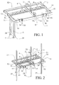
figure 1 est une vue en perspective d'une entretoise équipée d'un volet déplié. - La
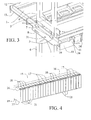
figure 2 est une vue en perspective d'une entretoise équipée d'un volet replié et dans laquelle ont été insérées des lames de renfort. - La
figure 3 est une vue en perspective et en agrandissement d'une partie du volet d'une première entretoise et d'une partie d'une deuxième entretoise. - La
figure 4 est une vue en perspective d'un bloc en matériau isolant. - La
figure 5 est une vue en perspective d'une partie d'un coffrage perdu (à savoir sans le grillage et les barres profilées). - La
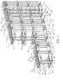
figure 6 est une vue en perspective d'un coffrage perdu.
- The
figure 1 is a perspective view of a spacer equipped with an unfolded flap. - The
figure 2 is a perspective view of a spacer equipped with a folded flap and in which were inserted reinforcing blades. - The
figure 3 is a perspective and enlarged view of a portion of the flap of a first spacer and a portion of a second spacer. - The
figure 4 is a perspective view of a block of insulating material. - The
figure 5 is a perspective view of a part of a lost formwork (ie without the grid and profiled bars). - The
figure 6 is a perspective view of a lost formwork.
Sur la
La traverse intermédiaire 2 est équipée d'un moyen de fixation 9 d'une gaine 20 (non représentée sur la
La traverse d'extrémité 13 est pourvue :
- d'un trou 31 pour accueillir une pointe (non représentée sur la
figure 1 ) qui sert à fixer l'entretoise 1 au sol ; d'une ouverture 8 pour accueillir une lame de renfort 35 (non représentée sur lafigure 1 ) ;- de deux ouvertures 5 pour la fixation d'un
volet 6d'une entretoise 1 non représentée sur lafigure 1 située au-dessus de l'entretoise 1.
- a
hole 31 to accommodate a tip (not shown on thefigure 1 ) which serves to fix thespacer 1 on the ground; - an
opening 8 for accommodating a reinforcing blade 35 (not shown in FIG.figure 1 ); - two
openings 5 for fixing aflap 6 of aspacer 1 not shown on thefigure 1 located above thespacer 1.
La traverse d'extrémité 14 est pourvue :
d'un emplacement 33 pour y accueillir un acier vertical 28 (non représenté sur lafigure 1 ),- d'un trou 31 pour accueillir une pointe (non représentée sur la
figure 1 ) qui sert à fixer l'entretoise 1 au sol.
- of a
location 33 to accommodate a vertical steel 28 (not shown on thefigure 1 ) - a
hole 31 to accommodate a tip (not shown on thefigure 1 ) which serves to fix thespacer 1 to the ground.
Le longeron intérieur 11 présente deux évidements 38 qui possèdent chacun des ergots 34 pour le clipsage de bords d'une barre profilée 22, ainsi qu'un plot 41 central situé entre les ergots 34 qui permet le vissage des barres pofilées 22 sur l'entretoise 1.The
Une pluralité d'ouvertures 4 sont ménagées dans le longeron intermédiaire 3.A plurality of
Des picots 10 pour les emplacements des aciers horizontaux 27 (non représentés sur la
Un même moule peut ainsi être utilisé pour fabriquer :
- d'une part les entretoises 1 destinées à être disposées sur le sol, et
- d'autre part les entretoises 1 disposées en hauteur les unes au-dessus des autres qui sont reliées entre elles au moyen d'un élément de
liaison 6.
- on the one hand the
spacers 1 intended to be arranged on the ground, and - on the other hand the
spacers 1 arranged in height above one another which are connected to each other by means of a connectingelement 6.
Le fait d'utiliser un moule standard pour fabriquer l'ensemble des entretoises 1 que comprend le coffrage perdu 29 selon l'invention est tout à fait avantageux d'un point de vue économique et pratique.The fact of using a standard mold to manufacture all the
L'élément de liaison 6 est constitué par un volet dont est équipée l'entretoise 1 et permet de l'assembler à une entretoise 1 (non représentée sur la
Le bord opposé 30 du volet 6 est muni d'une languette 39 qui bloque le mouvement vertical des aciers horizontaux 27 comme cela est visible sur la
Comme cela est représenté sur la
Sur la
Sur la
- sur une
face supérieure 16, deux rainures longitudinales 36, et 25bossages 17 qui sont délimitéspar 24 rainures transversales 18 ; - sur une face inférieure 19 opposée à la
face supérieure 16, deux rainures longitudinales 37, et 25 évidements (non visibles sur lafigure 4 ) qui sont délimitéspar 24 rainures transversales 21.
- on an
upper face 16, twolongitudinal grooves bosses 17 which are delimited by 24transverse grooves 18; - on a
lower face 19 opposite theupper face 16, twolongitudinal grooves figure 4 ) which are delimited by 24transverse grooves 21.
Ainsi, comme cela est représenté sur les
- les bossages 17 du bloc en matériau isolant inférieur 15 sont encastrés dans les ouvertures 4
d'une entretoise 1, - les traverses
d'extrémité la traverse intermédiaire 2 de l'entretoise 1 sont logées dans les rainures transversales 18,21 respectivement des blocs en matériau isolant supérieur et inférieur 15, - le longeron extérieur 12 est logé dans les rainures longitudinales 36,37 respectivement des blocs en matériau isolant supérieur et inférieur 15.
- the
bosses 17 of the block of lower insulatingmaterial 15 are embedded in theopenings 4 of aspacer 1, - the
end cross members intermediate cross member 2 of thespacer 1 are accommodated in thetransverse grooves material 15, - the
outer spar 12 is housed in thelongitudinal grooves material 15.
Aussi, les bossages 17 du bloc en matériau isolant inférieur 15 sont emboîtés dans les évidements du bloc en matériau isolant supérieur 15.Also, the
Les barres profilées 22 représentées sur la
Des profilés en équerre 40 sont disposés sur toute la longueur du mur du côté intérieur. Ils sont vissés sur les barres profilées 22 et sur la dalle. Ces profilés en équerre 40 permettent de fixer le grillage 26 en pied de mur. De cette manière, le grillage 26 est emprisonné entre les barres profilées 22 et les profilés en équerre 40.
Sur la
Claims (13)
et chaque entretoise (1) étant de forme générale rectangulaire, présentant un longeron extérieur (12) et un longeron intérieur (11) qui sont reliés entre eux par au moins deux traverses d'extrémité (13,14), le longeron extérieur (12) et les deux traverses d'extrémité (13,14) formant un des premiers moyens de fixation de l'entretoise (1) sur les blocs en matériau isolant (15).
and each spacer (1) being of generally rectangular shape, having an outer spar (12) and an inner spar (11) which are interconnected by at least two end cross members (13, 14), the outer spar (12) ) and the two end crosspieces (13,14) forming one of the first means for fixing the spacer (1) on the blocks of insulating material (15).
Applications Claiming Priority (1)
| Application Number | Priority Date | Filing Date | Title |
|---|---|---|---|
| FR1154880A FR2976005B1 (en) | 2011-06-06 | 2011-06-06 | LOST FORMWORK FOR CONCRETE WALL, IN PARTICULAR BUILDING |
Publications (2)
| Publication Number | Publication Date |
|---|---|
| EP2532798A1 true EP2532798A1 (en) | 2012-12-12 |
| EP2532798B1 EP2532798B1 (en) | 2015-04-01 |
Family
ID=46149341
Family Applications (1)
| Application Number | Title | Priority Date | Filing Date |
|---|---|---|---|
| EP20120170806 Active EP2532798B1 (en) | 2011-06-06 | 2012-06-05 | Lost formwork for concrete wall, in particular of a building |
Country Status (2)
| Country | Link |
|---|---|
| EP (1) | EP2532798B1 (en) |
| FR (1) | FR2976005B1 (en) |
Cited By (1)
| Publication number | Priority date | Publication date | Assignee | Title |
|---|---|---|---|---|
| WO2020169811A1 (en) | 2019-02-22 | 2020-08-27 | Mackencore Uk Limited | Lost formwork |
Citations (4)
| Publication number | Priority date | Publication date | Assignee | Title |
|---|---|---|---|---|
| US1958052A (en) * | 1930-04-30 | 1934-05-08 | Soundex Corp | Building construction |
| FR2540539A1 (en) | 1983-02-08 | 1984-08-10 | Ott Renaud | Constructional system using permanent formwork elements which are in particular insulating and reinforced |
| EP0118374A2 (en) * | 1983-02-08 | 1984-09-12 | Etablissements PATURLE | Construction system utilizing lost forms |
| WO2005042864A1 (en) | 2003-11-03 | 2005-05-12 | Polyfinance Coffor Holding S.A. | High-strength concrete wall formwork |
-
2011
- 2011-06-06 FR FR1154880A patent/FR2976005B1/en not_active Expired - Fee Related
-
2012
- 2012-06-05 EP EP20120170806 patent/EP2532798B1/en active Active
Patent Citations (4)
| Publication number | Priority date | Publication date | Assignee | Title |
|---|---|---|---|---|
| US1958052A (en) * | 1930-04-30 | 1934-05-08 | Soundex Corp | Building construction |
| FR2540539A1 (en) | 1983-02-08 | 1984-08-10 | Ott Renaud | Constructional system using permanent formwork elements which are in particular insulating and reinforced |
| EP0118374A2 (en) * | 1983-02-08 | 1984-09-12 | Etablissements PATURLE | Construction system utilizing lost forms |
| WO2005042864A1 (en) | 2003-11-03 | 2005-05-12 | Polyfinance Coffor Holding S.A. | High-strength concrete wall formwork |
Cited By (1)
| Publication number | Priority date | Publication date | Assignee | Title |
|---|---|---|---|---|
| WO2020169811A1 (en) | 2019-02-22 | 2020-08-27 | Mackencore Uk Limited | Lost formwork |
Also Published As
| Publication number | Publication date |
|---|---|
| EP2532798B1 (en) | 2015-04-01 |
| FR2976005B1 (en) | 2016-02-19 |
| FR2976005A1 (en) | 2012-12-07 |
Similar Documents
| Publication | Publication Date | Title |
|---|---|---|
| CA2746692C (en) | Foldable form panel block for building walls | |
| CA2398882A1 (en) | Structural profiled section in particular for partition | |
| EP3242980B1 (en) | Improved module forming a thermal bridge breaker for externally insulated buildings | |
| CA2377216A1 (en) | Elementary module for producing a breaker strip for a thermal bridge between a wall and a concrete slab and building structure comprising same | |
| FR2950638A1 (en) | Constructive system for building, has wall elements equipped with two concrete strips spaced and connected together by vertical spacers, where parts of strips blades external to spacers form walls of slide boxes of framework of building | |
| EP2532798B1 (en) | Lost formwork for concrete wall, in particular of a building | |
| FR2891290A1 (en) | Hollow framework element forming plates fixing device for forming e.g. wall of single family house, has posts assembled by transverse struts, where each post is inserted into one of plates and has length greater than or equal to two meters | |
| FR2969187A1 (en) | THERMALLY INSULATING PLATE PLATE | |
| WO2014053905A2 (en) | Structured beam and modular construction element made using said beam | |
| EP2476822B1 (en) | Thermal separator element intended for being installed at the junction between a cross wall and a façade shell of a reinforced concrete construction | |
| FR2827620A1 (en) | Thermally insulated connection between two perpendicular partitions of building, e.g. between a wall and floor slab, has insulating element on end of second partition inside first | |
| FR2952083A1 (en) | Balcony for frontage of apartment building, has surface water reception cavity provided with water evacuation opening, recovery unit recovering surface water, and plain slab whose surface area is inclined toward flow openings | |
| EP3087228B1 (en) | Foldable tridimensional form for structural walls | |
| FR3030590A1 (en) | SYSTEM AND METHOD FOR CONSTRUCTING A SPACER WALL | |
| FR3004482A1 (en) | FORMING DEVICE FOR CONCRETE WALLS | |
| EP2412882A2 (en) | Building block and wall structure obtained by assembling such building blocks | |
| EP3061880B1 (en) | Prefabricated balcony with ribs | |
| EP2071095B1 (en) | Beam comprising a light weight concrete boom and a partially embedded truss in this boom | |
| EP3106576B1 (en) | Pre-fabricated semi-ribbed balcony | |
| EP2354346A1 (en) | Construction element intended for building a wall | |
| EP2444567B1 (en) | Formwork element for building a beam | |
| FR2940337A1 (en) | Metallic joist for forming floor of building, has connection strip whose upper support comprises fixation tabs fixed on sheath, where strip is dimensioned so as to slide inside sheath before fixation on walls of sheath | |
| FR2893047A1 (en) | Construction block for forming ridge casing, has complimentary retaining grooves that extend from upper side to lower side of block and emerge out on lower side, where grooves fix insulating body on front side and body covers front side | |
| EP0085011A1 (en) | Self supporting panel for internal and external walls of buildings | |
| EP1585872A1 (en) | Wall building system |
Legal Events
| Date | Code | Title | Description |
|---|---|---|---|
| PUAI | Public reference made under article 153(3) epc to a published international application that has entered the european phase |
Free format text: ORIGINAL CODE: 0009012 |
|
| AK | Designated contracting states |
Kind code of ref document: A1 Designated state(s): AL AT BE BG CH CY CZ DE DK EE ES FI FR GB GR HR HU IE IS IT LI LT LU LV MC MK MT NL NO PL PT RO RS SE SI SK SM TR |
|
| AX | Request for extension of the european patent |
Extension state: BA ME |
|
| 17P | Request for examination filed |
Effective date: 20130604 |
|
| RBV | Designated contracting states (corrected) |
Designated state(s): AL AT BE BG CH CY CZ DE DK EE ES FI FR GB GR HR HU IE IS IT LI LT LU LV MC MK MT NL NO PL PT RO RS SE SI SK SM TR |
|
| GRAP | Despatch of communication of intention to grant a patent |
Free format text: ORIGINAL CODE: EPIDOSNIGR1 |
|
| RIC1 | Information provided on ipc code assigned before grant |
Ipc: E04B 2/86 20060101AFI20141113BHEP |
|
| INTG | Intention to grant announced |
Effective date: 20141128 |
|
| GRAS | Grant fee paid |
Free format text: ORIGINAL CODE: EPIDOSNIGR3 |
|
| GRAA | (expected) grant |
Free format text: ORIGINAL CODE: 0009210 |
|
| AK | Designated contracting states |
Kind code of ref document: B1 Designated state(s): AL AT BE BG CH CY CZ DE DK EE ES FI FR GB GR HR HU IE IS IT LI LT LU LV MC MK MT NL NO PL PT RO RS SE SI SK SM TR |
|
| REG | Reference to a national code |
Ref country code: GB Ref legal event code: FG4D Free format text: NOT ENGLISH |
|
| REG | Reference to a national code |
Ref country code: CH Ref legal event code: EP |
|
| REG | Reference to a national code |
Ref country code: IE Ref legal event code: FG4D Free format text: LANGUAGE OF EP DOCUMENT: FRENCH |
|
| REG | Reference to a national code |
Ref country code: AT Ref legal event code: REF Ref document number: 719181 Country of ref document: AT Kind code of ref document: T Effective date: 20150515 |
|
| REG | Reference to a national code |
Ref country code: DE Ref legal event code: R096 Ref document number: 602012006267 Country of ref document: DE Effective date: 20150521 |
|
| REG | Reference to a national code |
Ref country code: CH Ref legal event code: NV Representative=s name: CABINET GERMAIN AND MAUREAU, CH |
|
| REG | Reference to a national code |
Ref country code: NL Ref legal event code: VDEP Effective date: 20150401 |
|
| REG | Reference to a national code |
Ref country code: AT Ref legal event code: MK05 Ref document number: 719181 Country of ref document: AT Kind code of ref document: T Effective date: 20150401 |
|
| REG | Reference to a national code |
Ref country code: LT Ref legal event code: MG4D |
|
| PG25 | Lapsed in a contracting state [announced via postgrant information from national office to epo] |
Ref country code: NL Free format text: LAPSE BECAUSE OF FAILURE TO SUBMIT A TRANSLATION OF THE DESCRIPTION OR TO PAY THE FEE WITHIN THE PRESCRIBED TIME-LIMIT Effective date: 20150401 |
|
| PG25 | Lapsed in a contracting state [announced via postgrant information from national office to epo] |
Ref country code: LT Free format text: LAPSE BECAUSE OF FAILURE TO SUBMIT A TRANSLATION OF THE DESCRIPTION OR TO PAY THE FEE WITHIN THE PRESCRIBED TIME-LIMIT Effective date: 20150401 Ref country code: NO Free format text: LAPSE BECAUSE OF FAILURE TO SUBMIT A TRANSLATION OF THE DESCRIPTION OR TO PAY THE FEE WITHIN THE PRESCRIBED TIME-LIMIT Effective date: 20150701 Ref country code: ES Free format text: LAPSE BECAUSE OF FAILURE TO SUBMIT A TRANSLATION OF THE DESCRIPTION OR TO PAY THE FEE WITHIN THE PRESCRIBED TIME-LIMIT Effective date: 20150401 Ref country code: PT Free format text: LAPSE BECAUSE OF FAILURE TO SUBMIT A TRANSLATION OF THE DESCRIPTION OR TO PAY THE FEE WITHIN THE PRESCRIBED TIME-LIMIT Effective date: 20150803 Ref country code: FI Free format text: LAPSE BECAUSE OF FAILURE TO SUBMIT A TRANSLATION OF THE DESCRIPTION OR TO PAY THE FEE WITHIN THE PRESCRIBED TIME-LIMIT Effective date: 20150401 Ref country code: HR Free format text: LAPSE BECAUSE OF FAILURE TO SUBMIT A TRANSLATION OF THE DESCRIPTION OR TO PAY THE FEE WITHIN THE PRESCRIBED TIME-LIMIT Effective date: 20150401 Ref country code: CZ Free format text: LAPSE BECAUSE OF FAILURE TO SUBMIT A TRANSLATION OF THE DESCRIPTION OR TO PAY THE FEE WITHIN THE PRESCRIBED TIME-LIMIT Effective date: 20150401 |
|
| PG25 | Lapsed in a contracting state [announced via postgrant information from national office to epo] |
Ref country code: GR Free format text: LAPSE BECAUSE OF FAILURE TO SUBMIT A TRANSLATION OF THE DESCRIPTION OR TO PAY THE FEE WITHIN THE PRESCRIBED TIME-LIMIT Effective date: 20150702 Ref country code: RS Free format text: LAPSE BECAUSE OF FAILURE TO SUBMIT A TRANSLATION OF THE DESCRIPTION OR TO PAY THE FEE WITHIN THE PRESCRIBED TIME-LIMIT Effective date: 20150401 Ref country code: IS Free format text: LAPSE BECAUSE OF FAILURE TO SUBMIT A TRANSLATION OF THE DESCRIPTION OR TO PAY THE FEE WITHIN THE PRESCRIBED TIME-LIMIT Effective date: 20150801 Ref country code: LV Free format text: LAPSE BECAUSE OF FAILURE TO SUBMIT A TRANSLATION OF THE DESCRIPTION OR TO PAY THE FEE WITHIN THE PRESCRIBED TIME-LIMIT Effective date: 20150401 Ref country code: AT Free format text: LAPSE BECAUSE OF FAILURE TO SUBMIT A TRANSLATION OF THE DESCRIPTION OR TO PAY THE FEE WITHIN THE PRESCRIBED TIME-LIMIT Effective date: 20150401 |
|
| REG | Reference to a national code |
Ref country code: DE Ref legal event code: R119 Ref document number: 602012006267 Country of ref document: DE |
|
| PG25 | Lapsed in a contracting state [announced via postgrant information from national office to epo] |
Ref country code: DK Free format text: LAPSE BECAUSE OF FAILURE TO SUBMIT A TRANSLATION OF THE DESCRIPTION OR TO PAY THE FEE WITHIN THE PRESCRIBED TIME-LIMIT Effective date: 20150401 Ref country code: EE Free format text: LAPSE BECAUSE OF FAILURE TO SUBMIT A TRANSLATION OF THE DESCRIPTION OR TO PAY THE FEE WITHIN THE PRESCRIBED TIME-LIMIT Effective date: 20150401 Ref country code: MC Free format text: LAPSE BECAUSE OF FAILURE TO SUBMIT A TRANSLATION OF THE DESCRIPTION OR TO PAY THE FEE WITHIN THE PRESCRIBED TIME-LIMIT Effective date: 20150401 Ref country code: IT Free format text: LAPSE BECAUSE OF FAILURE TO SUBMIT A TRANSLATION OF THE DESCRIPTION OR TO PAY THE FEE WITHIN THE PRESCRIBED TIME-LIMIT Effective date: 20150401 |
|
| PLBE | No opposition filed within time limit |
Free format text: ORIGINAL CODE: 0009261 |
|
| STAA | Information on the status of an ep patent application or granted ep patent |
Free format text: STATUS: NO OPPOSITION FILED WITHIN TIME LIMIT |
|
| PG25 | Lapsed in a contracting state [announced via postgrant information from national office to epo] |
Ref country code: SK Free format text: LAPSE BECAUSE OF FAILURE TO SUBMIT A TRANSLATION OF THE DESCRIPTION OR TO PAY THE FEE WITHIN THE PRESCRIBED TIME-LIMIT Effective date: 20150401 Ref country code: LU Free format text: LAPSE BECAUSE OF FAILURE TO SUBMIT A TRANSLATION OF THE DESCRIPTION OR TO PAY THE FEE WITHIN THE PRESCRIBED TIME-LIMIT Effective date: 20150605 Ref country code: PL Free format text: LAPSE BECAUSE OF FAILURE TO SUBMIT A TRANSLATION OF THE DESCRIPTION OR TO PAY THE FEE WITHIN THE PRESCRIBED TIME-LIMIT Effective date: 20150401 Ref country code: RO Free format text: LAPSE BECAUSE OF NON-PAYMENT OF DUE FEES Effective date: 20150401 |
|
| 26N | No opposition filed |
Effective date: 20160105 |
|
| REG | Reference to a national code |
Ref country code: IE Ref legal event code: MM4A |
|
| REG | Reference to a national code |
Ref country code: FR Ref legal event code: PLFP Year of fee payment: 5 |
|
| PG25 | Lapsed in a contracting state [announced via postgrant information from national office to epo] |
Ref country code: IE Free format text: LAPSE BECAUSE OF NON-PAYMENT OF DUE FEES Effective date: 20150605 Ref country code: DE Free format text: LAPSE BECAUSE OF NON-PAYMENT OF DUE FEES Effective date: 20160101 |
|
| PG25 | Lapsed in a contracting state [announced via postgrant information from national office to epo] |
Ref country code: SI Free format text: LAPSE BECAUSE OF FAILURE TO SUBMIT A TRANSLATION OF THE DESCRIPTION OR TO PAY THE FEE WITHIN THE PRESCRIBED TIME-LIMIT Effective date: 20150401 |
|
| PG25 | Lapsed in a contracting state [announced via postgrant information from national office to epo] |
Ref country code: MT Free format text: LAPSE BECAUSE OF FAILURE TO SUBMIT A TRANSLATION OF THE DESCRIPTION OR TO PAY THE FEE WITHIN THE PRESCRIBED TIME-LIMIT Effective date: 20150401 |
|
| GBPC | Gb: european patent ceased through non-payment of renewal fee |
Effective date: 20160605 |
|
| REG | Reference to a national code |
Ref country code: FR Ref legal event code: PLFP Year of fee payment: 6 |
|
| PG25 | Lapsed in a contracting state [announced via postgrant information from national office to epo] |
Ref country code: HU Free format text: LAPSE BECAUSE OF FAILURE TO SUBMIT A TRANSLATION OF THE DESCRIPTION OR TO PAY THE FEE WITHIN THE PRESCRIBED TIME-LIMIT; INVALID AB INITIO Effective date: 20120605 Ref country code: GB Free format text: LAPSE BECAUSE OF NON-PAYMENT OF DUE FEES Effective date: 20160605 Ref country code: BG Free format text: LAPSE BECAUSE OF FAILURE TO SUBMIT A TRANSLATION OF THE DESCRIPTION OR TO PAY THE FEE WITHIN THE PRESCRIBED TIME-LIMIT Effective date: 20150401 Ref country code: SM Free format text: LAPSE BECAUSE OF FAILURE TO SUBMIT A TRANSLATION OF THE DESCRIPTION OR TO PAY THE FEE WITHIN THE PRESCRIBED TIME-LIMIT Effective date: 20150401 |
|
| PG25 | Lapsed in a contracting state [announced via postgrant information from national office to epo] |
Ref country code: SE Free format text: LAPSE BECAUSE OF FAILURE TO SUBMIT A TRANSLATION OF THE DESCRIPTION OR TO PAY THE FEE WITHIN THE PRESCRIBED TIME-LIMIT Effective date: 20150401 Ref country code: CY Free format text: LAPSE BECAUSE OF FAILURE TO SUBMIT A TRANSLATION OF THE DESCRIPTION OR TO PAY THE FEE WITHIN THE PRESCRIBED TIME-LIMIT Effective date: 20150401 |
|
| PG25 | Lapsed in a contracting state [announced via postgrant information from national office to epo] |
Ref country code: TR Free format text: LAPSE BECAUSE OF FAILURE TO SUBMIT A TRANSLATION OF THE DESCRIPTION OR TO PAY THE FEE WITHIN THE PRESCRIBED TIME-LIMIT Effective date: 20150401 |
|
| REG | Reference to a national code |
Ref country code: FR Ref legal event code: PLFP Year of fee payment: 7 |
|
| PG25 | Lapsed in a contracting state [announced via postgrant information from national office to epo] |
Ref country code: MK Free format text: LAPSE BECAUSE OF FAILURE TO SUBMIT A TRANSLATION OF THE DESCRIPTION OR TO PAY THE FEE WITHIN THE PRESCRIBED TIME-LIMIT Effective date: 20150401 |
|
| PGFP | Annual fee paid to national office [announced via postgrant information from national office to epo] |
Ref country code: CH Payment date: 20180629 Year of fee payment: 7 |
|
| PG25 | Lapsed in a contracting state [announced via postgrant information from national office to epo] |
Ref country code: AL Free format text: LAPSE BECAUSE OF FAILURE TO SUBMIT A TRANSLATION OF THE DESCRIPTION OR TO PAY THE FEE WITHIN THE PRESCRIBED TIME-LIMIT Effective date: 20150401 |
|
| PGFP | Annual fee paid to national office [announced via postgrant information from national office to epo] |
Ref country code: BE Payment date: 20180629 Year of fee payment: 7 |
|
| REG | Reference to a national code |
Ref country code: CH Ref legal event code: PL |
|
| REG | Reference to a national code |
Ref country code: BE Ref legal event code: MM Effective date: 20190630 |
|
| PG25 | Lapsed in a contracting state [announced via postgrant information from national office to epo] |
Ref country code: LI Free format text: LAPSE BECAUSE OF NON-PAYMENT OF DUE FEES Effective date: 20190630 Ref country code: CH Free format text: LAPSE BECAUSE OF NON-PAYMENT OF DUE FEES Effective date: 20190630 Ref country code: BE Free format text: LAPSE BECAUSE OF NON-PAYMENT OF DUE FEES Effective date: 20190630 |
|
| PGFP | Annual fee paid to national office [announced via postgrant information from national office to epo] |
Ref country code: FR Payment date: 20230419 Year of fee payment: 12 |