EP2531779B1 - Brennwertwärmetauscher für mehrere flüssigkeiten und brennwertkessel mit einem solchen wärmetauscher - Google Patents
Brennwertwärmetauscher für mehrere flüssigkeiten und brennwertkessel mit einem solchen wärmetauscher Download PDFInfo
- Publication number
- EP2531779B1 EP2531779B1 EP11703169.0A EP11703169A EP2531779B1 EP 2531779 B1 EP2531779 B1 EP 2531779B1 EP 11703169 A EP11703169 A EP 11703169A EP 2531779 B1 EP2531779 B1 EP 2531779B1
- Authority
- EP
- European Patent Office
- Prior art keywords
- exchanger
- primary
- tubes
- bundle
- fact
- Prior art date
- Legal status (The legal status is an assumption and is not a legal conclusion. Google has not performed a legal analysis and makes no representation as to the accuracy of the status listed.)
- Active
Links
Images


Classifications
-
- F—MECHANICAL ENGINEERING; LIGHTING; HEATING; WEAPONS; BLASTING
- F24—HEATING; RANGES; VENTILATING
- F24H—FLUID HEATERS, e.g. WATER OR AIR HEATERS, HAVING HEAT-GENERATING MEANS, e.g. HEAT PUMPS, IN GENERAL
- F24H1/00—Water heaters, e.g. boilers, continuous-flow heaters or water-storage heaters
- F24H1/22—Water heaters other than continuous-flow or water-storage heaters, e.g. water heaters for central heating
- F24H1/40—Water heaters other than continuous-flow or water-storage heaters, e.g. water heaters for central heating with water tube or tubes
- F24H1/43—Water heaters other than continuous-flow or water-storage heaters, e.g. water heaters for central heating with water tube or tubes helically or spirally coiled
-
- F—MECHANICAL ENGINEERING; LIGHTING; HEATING; WEAPONS; BLASTING
- F24—HEATING; RANGES; VENTILATING
- F24H—FLUID HEATERS, e.g. WATER OR AIR HEATERS, HAVING HEAT-GENERATING MEANS, e.g. HEAT PUMPS, IN GENERAL
- F24H1/00—Water heaters, e.g. boilers, continuous-flow heaters or water-storage heaters
- F24H1/48—Water heaters for central heating incorporating heaters for domestic water
- F24H1/52—Water heaters for central heating incorporating heaters for domestic water incorporating heat exchangers for domestic water
-
- F—MECHANICAL ENGINEERING; LIGHTING; HEATING; WEAPONS; BLASTING
- F24—HEATING; RANGES; VENTILATING
- F24H—FLUID HEATERS, e.g. WATER OR AIR HEATERS, HAVING HEAT-GENERATING MEANS, e.g. HEAT PUMPS, IN GENERAL
- F24H8/00—Fluid heaters characterised by means for extracting latent heat from flue gases by means of condensation
- F24H8/006—Means for removing condensate from the heater
-
- F—MECHANICAL ENGINEERING; LIGHTING; HEATING; WEAPONS; BLASTING
- F24—HEATING; RANGES; VENTILATING
- F24H—FLUID HEATERS, e.g. WATER OR AIR HEATERS, HAVING HEAT-GENERATING MEANS, e.g. HEAT PUMPS, IN GENERAL
- F24H9/00—Details
- F24H9/0005—Details for water heaters
- F24H9/001—Guiding means
- F24H9/0026—Guiding means in combustion gas channels
-
- F—MECHANICAL ENGINEERING; LIGHTING; HEATING; WEAPONS; BLASTING
- F28—HEAT EXCHANGE IN GENERAL
- F28D—HEAT-EXCHANGE APPARATUS, NOT PROVIDED FOR IN ANOTHER SUBCLASS, IN WHICH THE HEAT-EXCHANGE MEDIA DO NOT COME INTO DIRECT CONTACT
- F28D7/00—Heat-exchange apparatus having stationary tubular conduit assemblies for both heat-exchange media, the media being in contact with different sides of a conduit wall
- F28D7/0066—Multi-circuit heat-exchangers, e.g. integrating different heat exchange sections in the same unit or heat-exchangers for more than two fluids
- F28D7/0083—Multi-circuit heat-exchangers, e.g. integrating different heat exchange sections in the same unit or heat-exchangers for more than two fluids with units having particular arrangement relative to a supplementary heat exchange medium, e.g. with interleaved units or with adjacent units arranged in common flow of supplementary heat exchange medium
-
- F—MECHANICAL ENGINEERING; LIGHTING; HEATING; WEAPONS; BLASTING
- F28—HEAT EXCHANGE IN GENERAL
- F28D—HEAT-EXCHANGE APPARATUS, NOT PROVIDED FOR IN ANOTHER SUBCLASS, IN WHICH THE HEAT-EXCHANGE MEDIA DO NOT COME INTO DIRECT CONTACT
- F28D7/00—Heat-exchange apparatus having stationary tubular conduit assemblies for both heat-exchange media, the media being in contact with different sides of a conduit wall
- F28D7/02—Heat-exchange apparatus having stationary tubular conduit assemblies for both heat-exchange media, the media being in contact with different sides of a conduit wall the conduits being helically coiled
- F28D7/024—Heat-exchange apparatus having stationary tubular conduit assemblies for both heat-exchange media, the media being in contact with different sides of a conduit wall the conduits being helically coiled the conduits of only one medium being helically coiled tubes, the coils having a cylindrical configuration
-
- Y—GENERAL TAGGING OF NEW TECHNOLOGICAL DEVELOPMENTS; GENERAL TAGGING OF CROSS-SECTIONAL TECHNOLOGIES SPANNING OVER SEVERAL SECTIONS OF THE IPC; TECHNICAL SUBJECTS COVERED BY FORMER USPC CROSS-REFERENCE ART COLLECTIONS [XRACs] AND DIGESTS
- Y02—TECHNOLOGIES OR APPLICATIONS FOR MITIGATION OR ADAPTATION AGAINST CLIMATE CHANGE
- Y02B—CLIMATE CHANGE MITIGATION TECHNOLOGIES RELATED TO BUILDINGS, e.g. HOUSING, HOUSE APPLIANCES OR RELATED END-USER APPLICATIONS
- Y02B30/00—Energy efficient heating, ventilation or air conditioning [HVAC]
Definitions
- the present invention relates to a device for producing hot fluids, which comprises in particular a condensing heat exchanger for heating a plurality of fluids and means for producing a hot gas, such as a burner, in particular for gas or gas. fuel oil or means for supplying a hot gas produced beforehand by an external source.
- This device is intended in particular to equip a gas boiler for domestic or industrial applications, for example to supply a central heating circuit and / or to provide water for sanitary purposes.
- the heat exchanger of said device is of the type comprising an envelope which delimits an enclosure inside which is housed at least one bundle of tube (s), as described for example in the document EP-B-0 678 186 , which can be referred to as needed.
- EP-B-0 678 186 a heat exchanger element which consists of a tube of thermally good conductor material, in which a coolant, for example water to be heated, is intended to circulate.
- This tube is helically wound and has a flattened and oval cross-section whose major axis is substantially perpendicular to the axis of the helix, and each turn of the tube has plane faces which are spaced from the faces of the adjacent turn of the tube. a gap of constant width, this width being substantially smaller than the thickness of said cross section, the spacing between two adjacent turns being further calibrated by means of spacers, which consist of bosses formed in the wall of the tube; .
- An exchanger element thus designed is capable of providing a very efficient heat exchange between, on the one hand, very hot gases, which can be generated directly by a burner mounted in the enclosure, or come from an external source, which lick the tubular element, and, secondly, a fluid to be heated, such as water, which circulates inside thereof.
- Figure 20 of the document EP-B-0 678 186 thus shows a heat exchanger which comprises: a bundle of helically wound tubes acting as a primary heat exchanger, means for circulating a single primary fluid, a burner capable of generating hot gases, a ceramic disk attached to the heat exchanger, end of the burner and inside the bundle of tubes so as to compartmentalize the latter in two parts and an annular shutter disposed outside the bundle of tubes.
- Such an exchanger makes it possible, thanks to the two baffles formed by the disk and the shutter, to circulate the hot gases successively from the inside of the primary beam outwards, then downstream of the disk and upstream of the shutter of the outside to the inside, then finally to escape through the exhaust duct cooled gases.
- the condensing heat exchanger described in the document FR 2,854,229 , just makes it possible to heat a primary fluid and a secondary fluid.
- a gas impermeable envelope inside which are mounted a gas or oil burner, and two bundles of coaxial tubes, made of a thermally good conducting material, one of which acts as a primary exchanger and the other secondary exchanger, each of these bundles consisting of a tube, or a group of tubes arranged end to end and helically wound.
- means are provided for circulating two distinct fluids to be heated, said respectively “primary” and “secondary”, in particular cold water, inside the (the) tube (s) constitutive (s) respectively said primary beam and said secondary beam.
- two deflector plates are interposed between the primary beam and the secondary beam and are arranged parallel side by side, with a certain spacing, so that one closes one end of the primary beam and that the another closes the adjacent end of the secondary beam.
- These two plates thus define a space inside which circulates an additional hot gas, brought from an external conduit connected to the envelope.
- This additional hot gas thus participates in the heating of the secondary fluid through the turns of the tube bundle of the secondary exchanger.
- the presence of the second deflector plate (downstream plate) is only justified by the fact that it defines with the first a space for receiving the additional hot gas.
- the pair of plates is equivalent to a single baffle plate and this flow of hot gases will flow radially from the inside to the outside of the primary beam at the burner, then axially outside the winding bypassing the assembly formed by the two plates and finally, radially from the outside to the inside of the secondary beam, where the secondary fluid circulates.
- an exchanger absolutely does not allow to heat a secondary fluid separate from the primary fluid. Consequently, it does not include a secondary heat exchanger, nor means for circulating a secondary fluid, nor a baffle plate interposed between the primary heat exchanger and the secondary heat exchanger.
- this device does not include a condensing heat exchanger according to that of claim 1 and in particular does not include deflector plate positioned between a primary beam and a secondary beam.
- the invention therefore aims to provide a device for producing hot fluids comprising a condensing heat exchanger and whose overall efficiency is improved.
- Another object of the invention is to increase this overall efficiency while implementing means that do little to increase the cost price of the exchanger and do not increase its size too much.
- Another objective is to provide a device easy to manufacture in large series and easily scalable, so as to meet the different needs of the customer both in terms of the heat transfer capacity and the amounts of different fluids to be heated than in terms of clutter.
- said condensing heat exchanger comprises a second bundle of tubes acting as a secondary exchanger, fixedly mounted inside said casing coaxially with the first bundle of tubes and placed at the end thereof.
- this second beam also consisting of a tube, or a group of tubes arranged end to end, forming a spiral winding, in which the wall of the tube (s) is made of a thermally good conducting material, said second deflector plate is interposed between the primary beam and said secondary beam, this second deflector plate closing the interior space of said secondary beam, so that said hot gases pass through the secondary exchanger, passing through the interstices separating its turns from the exterior to the interior, before being finally discharged to the outside at low temperature, via said gas evacuation sleeve, and said device for producing hot fluids comprises means for circulating separately at least one fluid to be heated, said "secondary", distinct from the primary fluid, inside the tube (s) of said secondary beam, the circulation of this fluid secondary is also performed against the direction of that of said hot gases.
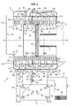
- the exchanger 1 shown in the figures comprises a shell, or envelope, 10 which delimits an enclosure inside which is fixedly mounted a double tubular bundle 2, which consists of two bundles of coaxial tubes placed end to end, of which one (2a) acts as a primary exchanger and the other (2b) as a secondary exchanger.
- This enclosure has approximately a generally cylindrical shape, of horizontal axis X-X ' .
- the beam 2a consists of a group of five adjacent tubes forming a helical winding, of axis X-X ', while the other beam 2b consists of two adjacent tubes, also helically wound, and of axis X- X '.
- the five tubes forming the bundle 2a and the two tubes forming the bundle 2b are identical, of the same length and of the same diameter.
- the beam 2a therefore has an axial dimension two and a half times greater than that of the beam 2b.
- Bosses (not shown) provided on the large faces of the tubes act as spacers, to delimit between each turn a gap of calibrated value, substantially constant.
- Each primary beam 2a and secondary 2b is intended to be traversed internally by at least one fluid to be heated, which is for example water.
- the two helical tubes of the secondary beam 2b are connected in series, the fluid to be heated being a single fluid, for example sanitary water, which flows from the left to the right when the we look at figures 1 and 2 .
- This fluid is hereinafter referred to as "secondary fluid" with reference to the beam in which it flows.
- the five helical tubes of the primary beam 2a (referenced 210, 220, 230, 240 and 250) are respectively connected in a group of two and in a group of three in parallel, and the two groups are connected in parallel. series, the fluid to be heated being a single fluid, for example water for heating premises. The fluid also flows from left to right if we consider the figures 1 and 2 . It is hereinafter referred to as "primary fluid".
- Lateral collectors 5 and 5 ' which are fixed to the casing 10, allow the connection of the apparatus, conventionally, respectively to two primary and secondary fluid supply ducts, cold, to be heated and on two ducts. evacuation of these same heated fluids.
- Each tube or tubular element has straight end portions, that is to say rectilinear axis, and of progressively variable section, whose opening end portion is circular.
- the inlet and outlet mouths of the tubular elements are crimped appropriately, and sealingly, in appropriate openings provided in the casing 10, to open into the collectors 5, 5 '.
- the inlet-outlet manifold 5 comprises four adjacent chambers separated by three internal partitions 51, 53 and 55, namely an inlet chamber 50 of the secondary fluid provided with a nozzle 500, an outlet chamber 52 of the secondary fluid. equipped with a nozzle 520, an inlet chamber 54 of the primary fluid provided with a nozzle 540 and an outlet chamber 56 of this primary fluid provided with a nozzle 560.
- the ends 500 and 520 are intended to be connected to a supply pipe 91 of the secondary fluid to be heated and, respectively, a discharge pipe 92 of the heated secondary fluid.
- the end pieces 540 and 560 are intended to be connected to a feed pipe 93 of the primary fluid to be heated and, respectively, a discharge pipe 94 of the heated primary fluid.
- the chamber 50 is connected to the inlet end portion 27'b of the tube 270 and the chamber 52 to the outlet end portion 26'b of the tube 260 of the bundle 2b.
- the chamber 54 is connected to the input end portions 24'a and 25'a of the two tubes 240 and 250 of the primary beam 2a, into which the primary fluid to be heated enters; the chamber 56 is connected to the outlet end portions 21'a, 22'a and 23'a of the three tubes 210, 220 and 230 of the primary beam 2a, through which the heated primary fluid exits.
- the opposite manifold 5 has two transfer chambers 57 and 59 separated by a partition 58.
- the transfer chamber 57 is connected to both the output end portion 27b and the input end portion 26b of the two elements of the secondary bundle 2b, 2a, and the transfer chamber 59 is connected to both the end portions of the output 24a and 25a of the tubes 240 and 250 of the primary beam 2a and the input end portions 21a, 22a and 23a of the three tubular elements 210, 220 and 230 of the beam 2a.
- the primary flow (arrows Ea) entering through the nozzle 540 is subdivided into two streams, each of which travels one winding (tube) 240, 250, meet in the chamber 59 and are transferred (arrows Ta) into the other three tubes 210, 220 and 230 to open (arrows Sa) in the chamber 56 and out through the tip 560.
- the circulation of this primary fluid is done for example by means of a pump 9.
- the incoming secondary flow (arrow Eb) enters via the nozzle 500, passes through the tube winding 270, then is transferred (arrow Tb) through the chamber 57 in the neighboring winding 260 to open (arrow Sb ) in the chamber 52 and out of the mouthpiece 520.
- the envelope 10, like the (or) tube (s) 210 to 270, may be metal, especially stainless steel.
- It is for example manufactured by roto-molding or by injection molding.
- the envelope is made for example of two half-shells which are heat-welded to each other after the tubular bundles have been installed inside one of them.
- the envelope 10 is open at its two ends, located on the right and on the left, if we consider the view of figures 1 and 2 .
- the opening formed in the front wall 14 of the casing 10 bears the reference 11 and that formed in the rear wall 15, the reference 12.
- part of the water vapor contained in the flue gases condenses on contact with the walls of the tubes 210 to 270.
- Reference 13 designates the bottom wall of the envelope 10; in known manner, this bottom is sloped, which allows the evacuation of condensate to an outlet (bonde) 130.
- the opening 12 is connected to an exhaust duct 122 of the cooled gases.
- the orifice 130 is connected to a condensate discharge conduit, while the sleeve 122 is connected to a flue gas discharge duct, for example a chimney flue.
- a flue gas discharge duct for example a chimney flue.
- the two roles hitherto devolved on the envelope are dissociated, namely, on the one hand, serving as an enclosure for the circulation and evacuation of hot gases, as well as for the collection and evacuation of condensates, and on the other hand, ensure the mechanical strength of the tube bundle.
- the bundles of tubes are preferably surrounded by a shell 16 forming a heat shield, to prevent the casing 10 from being directly exposed to the hot gases, in a similar arrangement to that described in the document FR 2,850,451 .
- the opening 11 on the front side of the envelope is closed by a front element 3, shown only in dotted lines, for simplification purposes.
- this facade element is attached to the envelope hermetically to the gases.
- a removable door provided with a central opening, through which a burner 4, for example a gas burner (or even fuel).
- the burner 4 is secured to the door.
- the door can also be made to present the structure described in the French patent application no. 09 51422 of March 6, 2009 , to which we can refer.
- the door comprises a pair of metal sheets, secured to one another at their periphery, the internal sheet being provided with an opening in which a burner is arranged and the outer sheet being connected to a control system. supplying a fuel gas to said burner.
- a baffle plate including itself two spaced walls and acting heat shield is inserted in the space between the two sheets of the door, to limit heat loss through the door and avoid the risk of burns at the door. contact with it, especially during maintenance work on the device by specialized personnel.
- Appropriate means connected to the burner 4 allow to bring to the apparatus, via a conduit, a mixture of gas and air fuel, such as propane and air in particular.
- These means may comprise a fan, not shown, capable of blowing the gas mixture into the burner.
- the burner 4 is a cylindrical tube with a closed end, whose wall is pierced with a multitude of small holes which allow the passage of the fuel mixture, radially from the inside to the outside of the tube.
- the outer surface of this wall constitutes the combustion surface.
- An ignition system of known type for example comprising a spark generator electrode, is obviously associated with the burner.
- this first part 200a thus comprises three windings of tubes 210, 220 and 230.
- the burner 4 could of course be replaced by a flat burner whose combustion surface would be perpendicular to the axis X-X 'or slightly curved.
- the interior space of the first part 200a of the tube bundle 2a is closed at its front end by the front element 3 and the door associated therewith and at its front end by a deflector plate 61 .
- This deflector plate 61 is constituted by a disc made of insulating material and refractory to heat, for example based on ceramic; it is supported by a discoid reinforcement in the form of a thin plate 610, in stainless steel, of larger diameter.
- the armature 610 is fixed between the last turn of the tube 230 and the first turn of the neighboring tube 240.
- the first part 200a of the tube bundle 2a is thus trapped axially between the front wall 14 and the deflector plate 61, whose armature 610 is fixed against its last turn.
- a second deflector plate 62 preferably not thermally insulated, is fixed between the last turn of the primary beam 2a, here the last turn of the tube 250, rear side (left on the figures 1 and 2 ) and the first turn of the secondary beam 2b, here the first turn of the tube 260, front side of the exchanger.
- this second deflector plate 62 is constituted by a disc supported by a discoidal reinforcement in the form of a thin plate 620, made of stainless steel, of larger diameter.
- the secondary beam 2b is thus trapped axially between the rear wall 15 of the casing 10 and the deflector 62, whose armature 620 is fixed against its last turn.
- the first and second deflector plates are thus centered on the X-X 'axis and parallel to each other.
- the deflector plates 61 and 62 are attached to the turns in a gas-tight manner.
- a discoidal deflector ring 63 is fixed around the primary beam 2a, that is to say outside the latter and inside the envelope 10. It is formed either from a thin sheet is made of a heat-resistant plastic material and consists of two half-rings assembled for example by crimping.
- This deflector ring 63 is supported both on the small outer side of one of the turns, here the last turn (left on the figures 1 and 2 ) of the fourth tube 240 and on the inner wall of the casing 10, for example by means of some guides molded in the casing 10 and not shown in the figure for the purpose of simplification (see also FIG. figure 3 ).
- this attachment is made so as to be gas-tight, for example by using a seal, so that the annular space extending between the outside of the bundles of tubes 2a and 2b and the inner wall of the envelope 10 is split into two parts that do not communicate directly.
- second part 200'a The portion of the primary beam 2a which extends axially between the deflector 61 and the deflector ring 63 is hereinafter referred to as "second part" 200'a. In the embodiment shown, it corresponds here to the only fourth tube 240.
- third part 200 "a hereinafter referred to as "third part” 200 "a, here it corresponds to the only fifth tube 250.
- the annular ferrule 16 is locked axially between the front wall 14 of the casing 10 and the deflector ring 63.
- this ferrule is obviously adapted to allow the passage to the various open ends 21a to 24a and 21'a to 24'a which cross to join the collectors 5, 5 '.
- This shell 16 is thus positioned opposite the first and second portions 200a and 200'a of the primary beam 2a which constitute the hottest zones of the exchanger.
- the two deflector plates 61, 62 and the deflector ring 63 constitute a series of three baffles in the path of the combustion gases.
- combustion chamber 71 that extending between the two deflector plates 61 and 62, “intermediate chamber 73 “, and that extending between the plate 62 and the sleeve 122,” evacuation chamber 75 ".
- the annular zones extending outside the bundle of tubes and inside the envelope 1 are respectively referenced 72, for that located between the front partition 14 and the ring 63, and 74 for that located between the ring 63 and the rear wall 15.
- the primary fluid to be heated, cold water for example, is circulated by the pump 9.
- a combustible gas mixture symbolized by the arrow I , is fed to the burner 4.
- the burner 4 having been ignited, the hot gases (combustion products) are generated by the latter in the combustion chamber 71. They constitute the sole source of hot gases used to heat the primary fluid and the secondary fluid, as described herein. -after.
- the gases are at a temperature of the order of 950 ° C to 1000 ° C. After passing through the portion 200a, these gases undergo a first cooling to arrive in the annular zone 72 at a temperature of the order of 100 ° C to 140 ° C.
- the gases then pass axially through the zone 72 (arrows i1 ), come into contact with the deflector ring 63 and are deflected so as to traverse radially the interstices separating the turns of the tube 240 (second part 200'a of the bundle 2a), outside to inside (arrow i2 ).
- the presence of the refractory material on the deflector plate 61 makes it possible to prevent the heat transfer from the burner 4 to the intermediate chamber 73.
- a third cooling of the gases takes place when the latter cross radially the turns of the tube 250 (third part 200 "of the beam 2a), from the inside to the outside (arrow i3 ), they can not escape axially due to the presence of the deflector plate 62.
- the gases reach the annular zone 74 at a temperature always lower than 75 ° C., in view of the previous cooling. This is important as will be detailed later.
- a fourth cooling occurs during the passage of gases through the interstices separating the turns of the secondary beam 2b, from the outside to the inside (arrows i4 ).
- the temperature of the combustion gases is lowered along their path, as a result of the heat transfer between these hot gases and the fluids flowing through the beams 2a and 2b and which flow countercurrently to the path of these gases.
- the deflector plate 62 constitutes a third baffle in the path of the hot gases.
- His position is important. It must always be located between the primary beam 2a and the secondary beam 2b. It makes it possible to significantly lower the temperature of the gases arriving in zone 74 and in particular to guarantee that it will always be below 75 ° C.
- the secondary fluid for example water
- present in the beam 2b may be either stagnant or circulating. In the case where it is stagnant, the presence of the deflector plate 62 prevents this secondary fluid is raised to a very high temperature, which could lead to the damage or rupture of the tubes 260 and 270 .
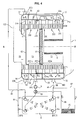
- the exchanger 1 above is used in the device for producing at least two hot fluids, according to the invention.
- Such a device is represented on the figure 2 and it comprises, in addition to the aforementioned condensing heat exchanger 1, a second exchanger 8.
- This second exchanger is for example a plate exchanger, known to those skilled in the art and which will not be described in detail.
- such an exchanger is composed of a set of superimposed parallel plates which delimit two heat exchange chambers traversed by the primary fluid and the secondary fluid, these two fluids flowing in the form of alternating thin layers. , with trajectories nested one inside the other.
- the inlet and outlet of the primary fluid is via a pair of mouths 82 and 84, respectively.
- the inlet and outlet of the secondary fluid is via a pair of mouths 81 and 83, respectively.
- mouths are formed in an end plate in the stack, via "wells", or inlet and outlet chimneys passing through the inner plates and communicating with the interstitial spaces constituting the corresponding enclosure.
- the plates of the exchanger are thin, thermally conductive metal plates, usually made of stainless steel, which are pressed and assembled by soldering or bonding by means of bolted flanges, with the interposition of rubber seals.
- the total number of plates is generally between ten and thirty for domestic power exchangers.
- the arrangement is designed so that the two streams of fluids between which the heat exchange occurs follow a labyrinth trajectory and flow against the current of each other, to promote this exchange.
- the discharge pipe 92 of the secondary fluid which has been preheated in the exchanger 1 is connected to the mouthpiece 81, while the discharge pipe 94 of the primary fluid which has been reheated in the exchanger 1 is connected to the mouthpiece 82.
- the mouth 84 is connected to the pump 9 via the feed pipe 93.
- the second heat exchanger 8 could also be a balloon intended to receive the primary fluid and through which a coil passes through which the secondary fluid circulates, or vice versa.
- the hot fluid generating device further comprises a three-way valve 99.
- This device can be connected, for example, to a central heating installation which comprises several radiators 96 (only one of which is shown in FIG. figure 2 ) or a heating slab that includes a serpentine tubing integrated into the floor.
- the radiator 96 is connected to the three-way valve 99 by a pipe 95 and the pipe 94 via a pipe 97 by a stitching or T-connection 98.
- the operation of the device is as follows.
- the pump 9 and the burner 4 are operated and the three-way valve 99 is positioned, so that the fluid primary circulates in the primary exchanger 2a, inside which it heats up to reach a certain temperature, for example 60 ° C, at the outlet of the nozzle 560, then in the radiator 96 before returning via the line 95, to the valve 99 and then back to the pump 9.
- a certain temperature for example 60 ° C
- the fluid path in the central heating circuit is represented by the arrows j.
- a drawing tap not shown in the figures makes it possible to circulate the water in the secondary circuit.
- the cold domestic water EFS enters the secondary heat exchanger 2b through the nozzle 500, circulates in the tubes 270 and 260, inside which it is heated by heat exchange with the gases present in the chambers 74 and 75, spring preheated via the discharge pipe 92, enters the exchanger 8 from which it leaves the desired temperature by the mouth 83, in the form of domestic hot water ECS.
- switching to "sanitary draw” mode causes the activation of the three-way valve 99 which passes into a position in which the return of the primary fluid from the pipe 95 is impossible.
- the primary fluid leaving the primary heat exchanger 2a is then directed to the heat exchanger 8 from which it emerges from the mouth 84 after having transmitted its heat to the secondary fluid, before returning to the pump 9.
- the heat exchanger 1 according to the invention and the device for producing hot fluid which includes it have particularly high performance compared to known devices of the prior art.
- the yield is in this case of the order of 96% to 97%.
- the outlet temperature of the fumes is conditioned by the temperature of the primary fluid which remains high, therefore, the fumes have a temperature which remains higher than the dew point which is at most 55 ° C. There is therefore no condensation in the main exchanger and no recovery of the latent heat contained in the fumes. The yield is therefore mediocre.
- the yield is in this case of the order of 107% to 109%, or even 110%, 10 to 12% higher than the state of the prior art.
- the device according to the invention makes it possible to obtain a double advantage.
- the EFS cold water that passes through the tubes 260 and 270 is at a very low temperature, of the order of 10 ° C.
- the products of combustion and fumes which pass into the interstices between these tubes are themselves themselves at a low temperature, of the order of 60 ° C. to 75 ° C. in the chamber 74, since they are at their third passage through the tubes of the primary exchanger.
- Their fourth passage through the tubes 260 and 270 containing water at 10 ° C further lowers their temperature, which explains the very good performance of the exchanger 1.
- the fact that the secondary fluid is preheated in the exchanger 1 reduces the amount of energy required to bring it to its final temperature.
- FIG. figure 4 A first variant embodiment of the condensing heat exchanger is shown in FIG. figure 4 .
- This exchanger differs from the previous in that the secondary heat exchanger 2a comprises only one tube 270 instead of two.
- the transfer chamber 57 is provided with a nozzle 570 which is connected to the discharge pipe 2 and the chamber 52 does not exist.
- FIG. figure 5 A second embodiment variant of the condensing heat exchanger is shown in FIG. figure 5 .
- first part 200a of the primary beam comprises only two tubes instead of three.
- the number of tubes of the different parts of the primary heat exchanger and the secondary heat exchanger can be adapted according to the needs of the user, provided that the plurality of deflector plates and the deflector ring which allow to cool the gases to the desired temperature.
- the hot gas present in the combustion chamber 71 is not necessarily generated by a burner housed in the primary beam. It can come from an external source and be conveyed inside the primary beam by means of a duct connected axially to the partition 3 and which then constitutes a means of supplying these gases.
- the device according to the invention could be used to heat other fluids, such as oil for example.
- the dimensions of the device governed in particular by the section, the diameter, and the length of the tubular bundles, as well as - where appropriate - by the type of burner implemented will of course be adapted to the desired power and conditions of use.
- the device may advantageously be equipped with a temperature probe adapted to stop the admission of hot gases when the probe detects a predetermined excessive temperature.
Landscapes
- Engineering & Computer Science (AREA)
- Physics & Mathematics (AREA)
- Thermal Sciences (AREA)
- Mechanical Engineering (AREA)
- General Engineering & Computer Science (AREA)
- Chemical & Material Sciences (AREA)
- Combustion & Propulsion (AREA)
- Heat-Exchange Devices With Radiators And Conduit Assemblies (AREA)
- Instantaneous Water Boilers, Portable Hot-Water Supply Apparatuses, And Control Of Portable Hot-Water Supply Apparatuses (AREA)
- Details Of Fluid Heaters (AREA)
Claims (14)
- Vorrichtung zur Erzeugung warmer Fluide, Folgendes umfassend: ein Mittel zur Zuführung oder ein Mittel zur Erzeugung (4) warmer Gase und einen Kondensationswärmetauscher (1), der Folgendes umfasst:- ein Röhrenbündel (2a), das als primärer Wärmetauscher dient, wobei das Bündel aus einer Röhre oder aus einem Satz von aneinandergefügten Röhren besteht, die eine schraubenförmige Aufwicklung bildet oder bilden, und wobei die Wand der einen oder mehreren Röhren aus einem gut wärmeleitenden Material hergestellt ist, wobei das Bündel (2a) im Inneren eines Mantels (10) fest montiert ist, der für die Gase undurchlässig ist und der mit einer Manschette (122) zum Abführen der Gase ausgestattet ist,- eine erste Ablenkplatte (61), die aus einem wärmeisolierenden und hitzebeständigen Material realisiert ist, beispielsweise auf Keramikbasis, und die zwischen zwei aufeinanderfolgenden Windungen des primären Bündels (2a) eingefügt ist, wobei die erste Ablenkplatte (61) auf der Achse (X-X') der Schraube zentriert ist und einen Teil des Innenraums des primären Bündels (2a) verschließt,- einen scheibenförmigen Ablenkring (63), der um das als primärer Wärmetauscher dienende Röhrenbündel (2a) herum angeordnet ist, und dies stromabwärts von der ersten Ablenkplatte (61) in Bezug auf die Strömungsrichtung der warmen Gase, wobei der Ablenkring (63) an seinem äußeren Rand am Mantel (10) und an seinem inneren Rand an einer der Windungen des primären Wärmetauschers (2a) befestigt ist,- eine zweite Ablenkplatte (62), die auf der Schraubenachse (X-X') zentriert ist,wobei die beiden Ablenkplatten (61, 62) und der Ablenkring (63) so angeordnet sind, dass die warmen Gase radial oder fast radial Folgendes durchströmen: zuerst einen ersten Teil (200a) des primären Wärmetauschers (2a), der sich stromaufwärts von der ersten Ablenkplatte (61) befindet, wobei sie die Lücken, die dessen Windungen trennen, von innen nach außen durchströmen, anschließend einen zweiten Teil (200'a) des primären Wärmetauschers (2a), der sich zwischen der ersten Ablenkplatte (61) und dem Ablenkring (63) erstreckt, wobei sie die Lücken, die dessen Windungen trennen, von außen nach innen durchströmen, und schließlich den letzten Teil des primären Wärmetauschers (200"a), der sich zwischen dem Ablenkring (63) und der zweiten Ablenkplatte (62) erstreckt, wobei sie die Lücken, die dessen Windungen trennen, von innen nach außen durchströmen,
wobei die Vorrichtung zur Erzeugung warmer Fluide außerdem ein Mittel (9) umfasst, um ein aufzuwärmendes Fluid, das als "primär" bezeichnet wird und bei dem es sich insbesondere um kaltes Wasser handelt, fließen zu lassen, und dies im Inneren der einen oder mehreren Röhren (210, 220, 230, 240, 250), die das Bündel (2a) bilden, das als primärer Wärmetauscher dient, wobei der Fluss des primären Fluids in der Gegenrichtung zu derjenigen der warmen Gase stattfindet,
wobei die Vorrichtung zur Erzeugung warmer Fluide dadurch gekennzeichnet ist, dass der Kondensationswärmetauscher (1) ein zweites Röhrenbündel (2b) umfasst, das als sekundärer Wärmetauscher dient und das im Inneren des Mantels (10) fest montiert ist, und dies koaxial zum ersten Röhrenbündel (2a) und an dessen Ende angeordnet, wobei das zweite Bündel (2b) ebenfalls aus einer Röhre oder aus einem Satz von aneinandergefügten Röhren besteht, die eine schraubenförmige Aufwicklung bildet oder bilden, und wobei die Wand der einen oder mehreren Röhren aus einem gut wärmeleitenden Material hergestellt ist, und dadurch, dass die zweite Ablenkplatte (62) zwischen dem primären Bündel (2a) und dem sekundären Bündel (2b) eingefügt ist, wobei die zweite Ablenkplatte (62) den Innenraum des sekundären Bündels (2b) derart verschließt, dass die warmen Gase durch den sekundären Wärmetauscher (2b) strömen, wobei sie die Lücken, die dessen Windungen trennen, von außen nach innen durchströmen, bevor sie schließlich mit niedriger Temperatur über die Manschette (122) zum Abführen der Gase nach außen abgeführt werden, und dadurch, dass die Vorrichtung zur Erzeugung warmer Fluide ein Mittel umfasst, um wenigstens ein aufzuwärmendes Fluid, das als "sekundär" bezeichnet wird und das vom primären Fluid verschieden ist, getrennt fließen zu lassen, und dies im Inneren der einen oder mehreren Röhren (260, 270) des sekundären Bündels (2b), wobei der Fluss des sekundären Fluids ebenfalls in der Gegenrichtung zu derjenigen der warmen Gase stattfindet. - Vorrichtung nach Anspruch 1, dadurch gekennzeichnet, dass das Mittel (4) zum Erzeugen von warmen Gasen ein Gas- oder Ölbrenner (4) ist.
- Vorrichtung nach Anspruch 1 oder 2, dadurch gekennzeichnet, dass der Ablenkring (63) zwischen den Windungen des primären Bündels (2a) und der Innenwand des Mantels (10) befestigt ist, und dies derart, dass der ringförmige Raum, der zwischen der Außenseite der Röhrenbündel (2a, 2b) und dem Mantel (10) ausgebildet ist, in zwei Zonen (72, 74) aufgeteilt wird, und dies auf eine für die Gase abdichtende Weise.
- Vorrichtung nach einem der vorhergehenden Ansprüche, dadurch gekennzeichnet, dass die Ablenkplatten (61, 62) Scheiben sind, die an den Windungen des primären (2a) und sekundären (2b) Bündels befestigt sind, und dies derart, dass sie den Innenraum der Bündel (2a, 2b) für die Gase abdichtend verschließen.
- Vorrichtung nach einem der vorhergehenden Ansprüche, dadurch gekennzeichnet, dass der Innenraum des ersten Teils (200a) des primären Wärmetauschers (2a), der als "Verbrennungskammer" (71) bezeichnet wird, an einem Ende durch die erste Ablenkplatte (61) verschlossen ist und an seinem anderen Ende durch eine Frontwand (3), die mit einer Türe ausgestattet ist, durch die das Mittel zur Zuführung oder zur Erzeugung (4) warmer Gase verläuft.
- Vorrichtung nach einem der vorhergehenden Ansprüche, dadurch gekennzeichnet, dass der Innenraum des Röhrenbündels (2b), das als sekundärer Wärmetauscher dient, der als "Abführungskammer" (75) bezeichnet wird, an einem Ende durch die zweite Ablenkplatte (62) verschlossen ist und an seinem anderen Ende mit der Manschette (122) zur Abführung der abgekühlten Gase verbunden ist.
- Vorrichtung nach einem der vorhergehenden Ansprüche, dadurch gekennzeichnet, dass die beiden Ablenkplatten (61, 62) und der scheibenförmige Ablenkring (63) zum einen parallel zueinander, zum anderen senkrecht zur Achse (X-X') der schraubenförmigen Aufwicklung der Röhrenbündel (2a, 2b) angeordnet sind.
- Vorrichtung nach einem der vorhergehenden Ansprüche, dadurch gekennzeichnet, dass die Breite der Lücke, die zwei benachbarte Windungen der Röhrenbündel (2a, 2b), die als primärer Wärmetauscher und als sekundärer Wärmetauscher dienen, trennt, konstant ist und insbesondere kleiner als die Dicke des Querschnitts der Röhren (210, 220, 230, 240, 250, 260, 270), die diese Bündel bilden.
- Vorrichtung nach einem der vorhergehenden Ansprüche, dadurch gekennzeichnet, dass die Wand der Röhren (210, 220, 230, 240, 250, 260, 270) der Bündel (2a, 2b) einen abgeflachten und ovalen Querschnitt hat, dessen große Achse senkrecht oder in etwa senkrecht zu derjenigen (X-X') der Schraube ist.
- Vorrichtung nach einem der vorhergehenden Ansprüche, dadurch gekennzeichnet, dass der Mantel (10) aus einem hitzebeständigen Kunststoffmaterial hergestellt ist, und dadurch, dass der Wärmetauscher (1) Mittel zur mechanischen Beaufschlagung der Röhrenbündel (2a, 2b), die in ihrer axialen Richtung koaxial sind, umfasst, wie etwa einen Satz Zugelemente, die außerhalb der Bündel angeordnet sind, parallel zur Achse (X-X') der Schraube, und deren Enden fest mit Auflageelementen verbunden sind, die an den beiden entgegengesetzten Enden der aneinandergefügt angeordneten Bündel anliegen, wobei die Beaufschlagungsmittel dafür eingerichtet sind, die Druckkräfte zu absorbieren, die sich aus dem inneren Druck der in den Röhren fließenden Fluide ergeben, der versucht deren Wände zu verformen, wobei vermieden wird, dass diese Kräfte auf den Mantel (10) übertragen werden.
- Vorrichtung nach einem der vorhergehenden Ansprüche, dadurch gekennzeichnet, dass der Mantel (10) aus einem hitzebeständigen Kunststoff hergestellt ist, und dadurch, dass der Wärmetauscher (1) einen Ringbeschlag (16) umfasst, der im Inneren des Mantels (10) und außerhalb des Röhrenbündels (2a), das als primärer Wärmetauscher dient, angeordnet ist, und dies auf einer Länge, die sich wenigstens entlang des ersten Teils (200a) des primären Wärmetauschers erstreckt, wobei der Ringbeschlag (16) die Funktion eines Hitzeschilds bereitstellt, die dafür geeignet ist, den Mantel (10) von der Hitze abzuschirmen, die von den warmen Gasen abgegeben wird.
- Vorrichtung nach einem der vorhergehenden Ansprüche, dadurch gekennzeichnet, dass sie einen zweiten Wärmetauscher (8) umfasst, der in Reihe mit dem Kondensationswärmetauscher (1) montiert ist, und dies derart, dass zum einen der Ausgang (560) des primären Fluids des Kondensationswärmetauschers (1) mit der Eingangsöffnung (82) des Primärkreislaufs des zweiten Wärmetauschers (8) verbunden ist und dass die Ausgangsöffnung (84) des primären Fluids des zweiten Wärmetauschers (8) mit dem Eingang (540) des primären Fluids des Kondensationswärmetauschers (1) verbunden ist, und das zum anderen der Ausgang (520, 570) des sekundären Fluids des Kondensationswärmetauschers (1) mit der Eingangsöffnung (81) des Sekundärkreislaufs des zweiten Wärmetauschers (8) verbunden ist und die Ausgangsöffnung (83) des sekundären Fluids des zweiten Wärmetauschers (8) mit dem Einspeisungspunkt des sekundären Fluids verbunden ist, wobei das warme primäre Fluid im Inneren des zweiten Wärmetauschers (8) gegen die Flussrichtung des sekundären Fluids, das im Kondensationswärmetauscher (1) vorgeheizt wurde, fließt.
- Vorrichtung nach Anspruch 12, dadurch gekennzeichnet, dass der zweite Wärmetauscher (8) ein Plattenwärmetauscher ist.
- Vorrichtung zur häuslichen Erzeugung eines sekundären Fluids, wie etwa häuslichem Warmwasser, und eines primären Fluids, wie etwa Heizungswasser, nach Anspruch 12 oder Anspruch 13, dadurch gekennzeichnet, dass sie ein Dreiwegventil (99) umfasst, dessen erster Weg mit der Ausgangsöffnung (84) des primären Fluids des zweiten Wärmetauschers (8) verbunden ist und dessen zweiter Weg mit dem Mittel (9) zum Fließen lassen verbunden ist, das seinerseits mit dem Eingang (540) des Primärkreislaufs des Kondensationswärmetauschers (1) verbunden ist, und dadurch, dass sie außerdem einen T-Anschluss (98) umfasst, von dem zwei Zweige mit dem Ausgang (560) des primären Fluids des Kondensationswärmetauschers (1) bzw. mit der Eingangsöffnung (82) des Primärkreislaufs des zweiten Wärmetauschers (8) verbunden sind, wobei der dritte Weg des Ventils (99) und der dritte Zweig des T-Anschlusses (98) dafür eingerichtet sind, mit den beiden Enden (95, 97) eines Heizungskreislaufs, beispielsweise einer Zentralheizung, verbunden zu werden.
Applications Claiming Priority (2)
| Application Number | Priority Date | Filing Date | Title |
|---|---|---|---|
| FR1050695A FR2955929B1 (fr) | 2010-02-01 | 2010-02-01 | Echangeur de chaleur a condensation pour plusieurs fluides et dispositif de production de fluides chauds comprenant un tel echangeur |
| PCT/EP2011/051326 WO2011092332A1 (fr) | 2010-02-01 | 2011-01-31 | Dispositif de production de fluides chauds comprenant un echangeur de chaleur a condensation |
Publications (2)
| Publication Number | Publication Date |
|---|---|
| EP2531779A1 EP2531779A1 (de) | 2012-12-12 |
| EP2531779B1 true EP2531779B1 (de) | 2014-03-05 |
Family
ID=42697503
Family Applications (1)
| Application Number | Title | Priority Date | Filing Date |
|---|---|---|---|
| EP11703169.0A Active EP2531779B1 (de) | 2010-02-01 | 2011-01-31 | Brennwertwärmetauscher für mehrere flüssigkeiten und brennwertkessel mit einem solchen wärmetauscher |
Country Status (9)
| Country | Link |
|---|---|
| US (1) | US9476610B2 (de) |
| EP (1) | EP2531779B1 (de) |
| JP (1) | JP5539543B2 (de) |
| KR (1) | KR101740010B1 (de) |
| CN (1) | CN102822607B (de) |
| CA (1) | CA2786897C (de) |
| FR (1) | FR2955929B1 (de) |
| RU (1) | RU2514572C1 (de) |
| WO (1) | WO2011092332A1 (de) |
Families Citing this family (17)
| Publication number | Priority date | Publication date | Assignee | Title |
|---|---|---|---|---|
| US9353967B2 (en) * | 2010-02-03 | 2016-05-31 | Farshid Ahmady | Fluid heating apparatus |
| CN102901222B (zh) * | 2012-09-21 | 2016-04-20 | 苏州成强能源科技有限公司 | 一种强制翅片直管双环状冷凝供热换热器 |
| PL3139106T3 (pl) | 2014-03-17 | 2019-07-31 | Condevo S.P.A. | Komórka wymiany ciepła i sposób |
| KR101596284B1 (ko) * | 2014-03-18 | 2016-02-23 | 주식회사 경동나비엔 | 열교환기 |
| US9631808B2 (en) * | 2014-11-21 | 2017-04-25 | Honeywell International Inc. | Fuel-air-flue gas burner |
| US10024603B2 (en) * | 2014-11-26 | 2018-07-17 | Riello S.P.A. | Double tubing condensation exchanger for heating water and/or for producing sanitary hot water |
| CN108291739B (zh) * | 2015-06-24 | 2020-06-05 | 意大利利雅路股份有限公司 | 管道的型材、盘绕式热交换器以及冷凝锅炉 |
| WO2017102490A1 (de) * | 2015-12-17 | 2017-06-22 | Vaillant Gmbh | Primärwärmetauschereinheit |
| FR3047549B1 (fr) * | 2016-02-09 | 2019-05-10 | Sermeta | Deflecteur pour echangeur de chaleur a condensation et echangeur muni d'un tel deflecteur |
| DE102016215210A1 (de) * | 2016-08-16 | 2018-02-22 | Vaillant Gmbh | Wendelförmiger Heizungswärmetauscher |
| NL2016755B1 (nl) * | 2016-05-10 | 2017-11-16 | Remeha B V | Warmtewisselaar. |
| FR3062471B1 (fr) * | 2017-01-27 | 2019-06-07 | Sermeta | Echangeur de chaleur |
| US10753644B2 (en) | 2017-08-04 | 2020-08-25 | A. O. Smith Corporation | Water heater |
| US11644246B2 (en) | 2017-11-29 | 2023-05-09 | Condevo S.P.A. | Heat exchange cell and method |
| US11747042B2 (en) | 2019-12-23 | 2023-09-05 | Rheem Manufacturing Company | Systems and methods for managing temperature control of bodies of water |
| FR3125326B1 (fr) * | 2021-07-16 | 2023-07-14 | Sermeta | Echangeur de chaleur |
| IT202100030593A1 (it) * | 2021-12-02 | 2023-06-02 | La Nuova Coterm Srl | Caldaia e suo uso |
Family Cites Families (16)
| Publication number | Priority date | Publication date | Assignee | Title |
|---|---|---|---|---|
| CH229954A (de) | 1941-07-25 | 1943-11-30 | Hermes Patentverwertungs Gmbh | Schalteinrichtung für hohe Schaltgeschwindigkeiten. |
| DE3014180A1 (de) * | 1980-04-14 | 1982-02-04 | Kernforschungsanlage Jülich GmbH, 5170 Jülich | Heizungseinrichtung mit keramischen brennkopf sowie mit einem brennraum und einem rekuperator aus keramik |
| JPS5966646A (ja) * | 1982-10-06 | 1984-04-16 | Matsushita Electric Ind Co Ltd | 温水ボイラ |
| DE8530184U1 (de) * | 1985-10-22 | 1986-05-07 | Joh. Vaillant Gmbh U. Co, 5630 Remscheid | Wasserheizgerät |
| FR2700608B1 (fr) * | 1993-01-15 | 1995-04-07 | Joseph Le Mer | Elément échangeur de chaleur, procédé et dispositif pour le fabriquer. |
| ITRM20010474A1 (it) * | 2001-08-03 | 2003-02-03 | Fontecal S P A | Scambiatore spiroidale ad alto rendimento per riscaldamento e/o produzione di acqua calda sanitaria, particolarmente adatto alla condensazio |
| FR2843189B1 (fr) * | 2002-07-30 | 2004-10-15 | Mer Joseph Le | "echangeur de chaleur a condensation a double faisceau de tubes" |
| JP4087407B2 (ja) * | 2002-10-16 | 2008-05-21 | ソシエテ、デチュード、エ、ド、レアリザシオン、メカニク、エンジニアリング、アン、テクノロジーズ、アバンセ | プラスチックケーシングを有する凝縮熱交換器 |
| FR2850451B3 (fr) * | 2003-01-24 | 2005-04-15 | Realisation Mecaniques Engenee | Echangeur de chaleur a condensation, a enveloppe plastique |
| FR2846075B1 (fr) * | 2002-10-16 | 2005-03-04 | Realisation Mecaniques Engenee | Echangeur de chaleur a condensation, a enveloppe plastique |
| FR2854229A1 (fr) * | 2003-04-25 | 2004-10-29 | Realisation Mecaniques Engenee | Echangeur de chaleur a condensation |
| JP2005321170A (ja) * | 2004-05-11 | 2005-11-17 | Noritz Corp | 瞬間式加熱装置および給湯装置 |
| WO2005108875A1 (ja) * | 2004-05-11 | 2005-11-17 | Noritz Corporation | 熱交換器および温水装置 |
| JP2007187419A (ja) * | 2006-01-16 | 2007-07-26 | Rinnai Corp | 給湯暖房装置 |
| SE529808C2 (sv) | 2006-04-06 | 2007-11-27 | Alfa Laval Corp Ab | Plattvärmeväxlare |
| FR2942866B1 (fr) | 2009-03-06 | 2012-03-23 | Mer Joseph Le | Porte a bruleur integre pour appareil de chauffage |
-
2010
- 2010-02-01 FR FR1050695A patent/FR2955929B1/fr not_active Expired - Fee Related
-
2011
- 2011-01-31 WO PCT/EP2011/051326 patent/WO2011092332A1/fr not_active Ceased
- 2011-01-31 CN CN201180007530.3A patent/CN102822607B/zh active Active
- 2011-01-31 CA CA2786897A patent/CA2786897C/fr active Active
- 2011-01-31 KR KR1020127023084A patent/KR101740010B1/ko active Active
- 2011-01-31 US US13/576,248 patent/US9476610B2/en active Active
- 2011-01-31 RU RU2012137283/06A patent/RU2514572C1/ru active
- 2011-01-31 EP EP11703169.0A patent/EP2531779B1/de active Active
- 2011-01-31 JP JP2012550473A patent/JP5539543B2/ja active Active
Also Published As
| Publication number | Publication date |
|---|---|
| US20120312513A1 (en) | 2012-12-13 |
| FR2955929B1 (fr) | 2014-04-18 |
| RU2514572C1 (ru) | 2014-04-27 |
| KR20130016207A (ko) | 2013-02-14 |
| JP5539543B2 (ja) | 2014-07-02 |
| EP2531779A1 (de) | 2012-12-12 |
| JP2013518241A (ja) | 2013-05-20 |
| CA2786897A1 (fr) | 2011-08-04 |
| WO2011092332A1 (fr) | 2011-08-04 |
| KR101740010B1 (ko) | 2017-05-25 |
| CN102822607A (zh) | 2012-12-12 |
| US9476610B2 (en) | 2016-10-25 |
| RU2012137283A (ru) | 2014-03-10 |
| CA2786897C (fr) | 2017-08-01 |
| FR2955929A1 (fr) | 2011-08-05 |
| CN102822607B (zh) | 2015-09-30 |
Similar Documents
| Publication | Publication Date | Title |
|---|---|---|
| EP2531779B1 (de) | Brennwertwärmetauscher für mehrere flüssigkeiten und brennwertkessel mit einem solchen wärmetauscher | |
| EP1618341B1 (de) | Brennwertwärmetauscher | |
| EP1561075B1 (de) | Kondensationswärmetauscher mit kunststoffmantel | |
| EP3405723B1 (de) | Kondensationswärmetauscher mit einer wärmetauschervorrichtung | |
| EP1532407B1 (de) | Wärmetauscher für ein brennwertgerät mit doppelrohrbündel | |
| FR2913105A1 (fr) | "echangeur de chaleur a condensation comprenant deux faisceaux primaires et un faisceau secondaire" | |
| FR2846075A1 (fr) | Echangeur de chaleur a condensation, a enveloppe plastique | |
| FR3033025A1 (fr) | Alambic equipe d'un tour a feu a deux etages | |
| FR3117042A1 (fr) | Dispositif de distillation présentant une consommation énergétique réduite | |
| FR3033026A1 (fr) | Alambic equipe d'un bruleur a gaz ameliore | |
| EP1366326B1 (de) | Kondensierender wärmetauscher für einen kessel | |
| EP2378197B1 (de) | Leitung für eine Anlage zum Abführen von Verbrennungsprodukten und zum Zuführen von Verbrennungsluft | |
| FR2494830A1 (fr) | Element d'echange de chaleur forme de tubes en forme de serpentins en matiere plastique et recuperateur de chaleur le mettant en oeuvre | |
| FR3033027A1 (fr) | Alambic equipe d'un tour a feu avec isolation renforcee | |
| CA2012714A1 (fr) | Procede et appareil de chauffage d'un flux de fluide gazeux par echanges thermiques successifs | |
| FR2850451A1 (fr) | Echangeur de chaleur a condensation, a enveloppe plastique | |
| FR2664784A1 (fr) | Rechauffeur de fluide utilisant des tubes chauffes par effet joule qui transmettent leur energie simultanement par leurs faces interne et externe. | |
| EP0051036B1 (de) | Oberflächenwärmetauscher zur Wärmerückgewinnung | |
| FR2530795A1 (fr) | Dispositif pour chauffer des recipients et/ou les maintenir a temperature, par exemple pour des recipients contenant un metal en fusion. | |
| FR2510245A1 (fr) | Echangeurs de chaleur a surfaces d'echange plissee et systemes de prelevement des calories evacuees par les fumees sortant des chambres de combustion | |
| FR2714151A1 (fr) | Dispositif d'accrochage de flammes et d'échange de chaleur, brûleur et chauffe-fluide ainsi équipés . | |
| FR2462684A1 (fr) | Echangeur de chaleur a paroi developpable et a deux fluides circulant a contre-courant | |
| FR2984996A1 (fr) | Conduit recuperateur de chaleur |
Legal Events
| Date | Code | Title | Description |
|---|---|---|---|
| PUAI | Public reference made under article 153(3) epc to a published international application that has entered the european phase |
Free format text: ORIGINAL CODE: 0009012 |
|
| 17P | Request for examination filed |
Effective date: 20120711 |
|
| AK | Designated contracting states |
Kind code of ref document: A1 Designated state(s): AL AT BE BG CH CY CZ DE DK EE ES FI FR GB GR HR HU IE IS IT LI LT LU LV MC MK MT NL NO PL PT RO RS SE SI SK SM TR |
|
| DAX | Request for extension of the european patent (deleted) | ||
| GRAP | Despatch of communication of intention to grant a patent |
Free format text: ORIGINAL CODE: EPIDOSNIGR1 |
|
| INTG | Intention to grant announced |
Effective date: 20131009 |
|
| GRAS | Grant fee paid |
Free format text: ORIGINAL CODE: EPIDOSNIGR3 |
|
| GRAA | (expected) grant |
Free format text: ORIGINAL CODE: 0009210 |
|
| AK | Designated contracting states |
Kind code of ref document: B1 Designated state(s): AL AT BE BG CH CY CZ DE DK EE ES FI FR GB GR HR HU IE IS IT LI LT LU LV MC MK MT NL NO PL PT RO RS SE SI SK SM TR |
|
| REG | Reference to a national code |
Ref country code: GB Ref legal event code: FG4D Free format text: NOT ENGLISH |
|
| REG | Reference to a national code |
Ref country code: CH Ref legal event code: EP |
|
| REG | Reference to a national code |
Ref country code: AT Ref legal event code: REF Ref document number: 655155 Country of ref document: AT Kind code of ref document: T Effective date: 20140315 |
|
| REG | Reference to a national code |
Ref country code: IE Ref legal event code: FG4D Free format text: LANGUAGE OF EP DOCUMENT: FRENCH |
|
| REG | Reference to a national code |
Ref country code: DE Ref legal event code: R096 Ref document number: 602011005272 Country of ref document: DE Effective date: 20140417 |
|
| REG | Reference to a national code |
Ref country code: NL Ref legal event code: T3 |
|
| REG | Reference to a national code |
Ref country code: AT Ref legal event code: MK05 Ref document number: 655155 Country of ref document: AT Kind code of ref document: T Effective date: 20140305 |
|
| PG25 | Lapsed in a contracting state [announced via postgrant information from national office to epo] |
Ref country code: NO Free format text: LAPSE BECAUSE OF FAILURE TO SUBMIT A TRANSLATION OF THE DESCRIPTION OR TO PAY THE FEE WITHIN THE PRESCRIBED TIME-LIMIT Effective date: 20140605 Ref country code: LT Free format text: LAPSE BECAUSE OF FAILURE TO SUBMIT A TRANSLATION OF THE DESCRIPTION OR TO PAY THE FEE WITHIN THE PRESCRIBED TIME-LIMIT Effective date: 20140305 |
|
| REG | Reference to a national code |
Ref country code: LT Ref legal event code: MG4D |
|
| PG25 | Lapsed in a contracting state [announced via postgrant information from national office to epo] |
Ref country code: SE Free format text: LAPSE BECAUSE OF FAILURE TO SUBMIT A TRANSLATION OF THE DESCRIPTION OR TO PAY THE FEE WITHIN THE PRESCRIBED TIME-LIMIT Effective date: 20140305 Ref country code: AT Free format text: LAPSE BECAUSE OF FAILURE TO SUBMIT A TRANSLATION OF THE DESCRIPTION OR TO PAY THE FEE WITHIN THE PRESCRIBED TIME-LIMIT Effective date: 20140305 Ref country code: FI Free format text: LAPSE BECAUSE OF FAILURE TO SUBMIT A TRANSLATION OF THE DESCRIPTION OR TO PAY THE FEE WITHIN THE PRESCRIBED TIME-LIMIT Effective date: 20140305 Ref country code: CY Free format text: LAPSE BECAUSE OF FAILURE TO SUBMIT A TRANSLATION OF THE DESCRIPTION OR TO PAY THE FEE WITHIN THE PRESCRIBED TIME-LIMIT Effective date: 20140305 |
|
| PG25 | Lapsed in a contracting state [announced via postgrant information from national office to epo] |
Ref country code: HR Free format text: LAPSE BECAUSE OF FAILURE TO SUBMIT A TRANSLATION OF THE DESCRIPTION OR TO PAY THE FEE WITHIN THE PRESCRIBED TIME-LIMIT Effective date: 20140305 Ref country code: LV Free format text: LAPSE BECAUSE OF FAILURE TO SUBMIT A TRANSLATION OF THE DESCRIPTION OR TO PAY THE FEE WITHIN THE PRESCRIBED TIME-LIMIT Effective date: 20140305 Ref country code: RS Free format text: LAPSE BECAUSE OF FAILURE TO SUBMIT A TRANSLATION OF THE DESCRIPTION OR TO PAY THE FEE WITHIN THE PRESCRIBED TIME-LIMIT Effective date: 20140305 |
|
| REG | Reference to a national code |
Ref country code: FR Ref legal event code: CD Owner name: SERMETA, FR Effective date: 20140903 |
|
| REG | Reference to a national code |
Ref country code: FR Ref legal event code: GC Effective date: 20140919 |
|
| PG25 | Lapsed in a contracting state [announced via postgrant information from national office to epo] |
Ref country code: EE Free format text: LAPSE BECAUSE OF FAILURE TO SUBMIT A TRANSLATION OF THE DESCRIPTION OR TO PAY THE FEE WITHIN THE PRESCRIBED TIME-LIMIT Effective date: 20140305 Ref country code: RO Free format text: LAPSE BECAUSE OF FAILURE TO SUBMIT A TRANSLATION OF THE DESCRIPTION OR TO PAY THE FEE WITHIN THE PRESCRIBED TIME-LIMIT Effective date: 20140305 Ref country code: CZ Free format text: LAPSE BECAUSE OF FAILURE TO SUBMIT A TRANSLATION OF THE DESCRIPTION OR TO PAY THE FEE WITHIN THE PRESCRIBED TIME-LIMIT Effective date: 20140305 Ref country code: IS Free format text: LAPSE BECAUSE OF FAILURE TO SUBMIT A TRANSLATION OF THE DESCRIPTION OR TO PAY THE FEE WITHIN THE PRESCRIBED TIME-LIMIT Effective date: 20140705 Ref country code: BG Free format text: LAPSE BECAUSE OF FAILURE TO SUBMIT A TRANSLATION OF THE DESCRIPTION OR TO PAY THE FEE WITHIN THE PRESCRIBED TIME-LIMIT Effective date: 20140605 |
|
| PG25 | Lapsed in a contracting state [announced via postgrant information from national office to epo] |
Ref country code: ES Free format text: LAPSE BECAUSE OF FAILURE TO SUBMIT A TRANSLATION OF THE DESCRIPTION OR TO PAY THE FEE WITHIN THE PRESCRIBED TIME-LIMIT Effective date: 20140305 Ref country code: PL Free format text: LAPSE BECAUSE OF FAILURE TO SUBMIT A TRANSLATION OF THE DESCRIPTION OR TO PAY THE FEE WITHIN THE PRESCRIBED TIME-LIMIT Effective date: 20140305 Ref country code: SK Free format text: LAPSE BECAUSE OF FAILURE TO SUBMIT A TRANSLATION OF THE DESCRIPTION OR TO PAY THE FEE WITHIN THE PRESCRIBED TIME-LIMIT Effective date: 20140305 |
|
| REG | Reference to a national code |
Ref country code: DE Ref legal event code: R097 Ref document number: 602011005272 Country of ref document: DE |
|
| PG25 | Lapsed in a contracting state [announced via postgrant information from national office to epo] |
Ref country code: PT Free format text: LAPSE BECAUSE OF FAILURE TO SUBMIT A TRANSLATION OF THE DESCRIPTION OR TO PAY THE FEE WITHIN THE PRESCRIBED TIME-LIMIT Effective date: 20140707 |
|
| PLBE | No opposition filed within time limit |
Free format text: ORIGINAL CODE: 0009261 |
|
| STAA | Information on the status of an ep patent application or granted ep patent |
Free format text: STATUS: NO OPPOSITION FILED WITHIN TIME LIMIT |
|
| PG25 | Lapsed in a contracting state [announced via postgrant information from national office to epo] |
Ref country code: DK Free format text: LAPSE BECAUSE OF FAILURE TO SUBMIT A TRANSLATION OF THE DESCRIPTION OR TO PAY THE FEE WITHIN THE PRESCRIBED TIME-LIMIT Effective date: 20140305 |
|
| 26N | No opposition filed |
Effective date: 20141208 |
|
| REG | Reference to a national code |
Ref country code: DE Ref legal event code: R097 Ref document number: 602011005272 Country of ref document: DE Effective date: 20141208 |
|
| PG25 | Lapsed in a contracting state [announced via postgrant information from national office to epo] |
Ref country code: SI Free format text: LAPSE BECAUSE OF FAILURE TO SUBMIT A TRANSLATION OF THE DESCRIPTION OR TO PAY THE FEE WITHIN THE PRESCRIBED TIME-LIMIT Effective date: 20140305 |
|
| PG25 | Lapsed in a contracting state [announced via postgrant information from national office to epo] |
Ref country code: BE Free format text: LAPSE BECAUSE OF NON-PAYMENT OF DUE FEES Effective date: 20150131 |
|
| REG | Reference to a national code |
Ref country code: CH Ref legal event code: PL |
|
| PG25 | Lapsed in a contracting state [announced via postgrant information from national office to epo] |
Ref country code: LU Free format text: LAPSE BECAUSE OF FAILURE TO SUBMIT A TRANSLATION OF THE DESCRIPTION OR TO PAY THE FEE WITHIN THE PRESCRIBED TIME-LIMIT Effective date: 20150131 |
|
| PG25 | Lapsed in a contracting state [announced via postgrant information from national office to epo] |
Ref country code: MC Free format text: LAPSE BECAUSE OF FAILURE TO SUBMIT A TRANSLATION OF THE DESCRIPTION OR TO PAY THE FEE WITHIN THE PRESCRIBED TIME-LIMIT Effective date: 20140305 |
|
| PG25 | Lapsed in a contracting state [announced via postgrant information from national office to epo] |
Ref country code: CH Free format text: LAPSE BECAUSE OF NON-PAYMENT OF DUE FEES Effective date: 20150131 Ref country code: LI Free format text: LAPSE BECAUSE OF NON-PAYMENT OF DUE FEES Effective date: 20150131 |
|
| REG | Reference to a national code |
Ref country code: IE Ref legal event code: MM4A |
|
| REG | Reference to a national code |
Ref country code: FR Ref legal event code: PLFP Year of fee payment: 6 |
|
| PG25 | Lapsed in a contracting state [announced via postgrant information from national office to epo] |
Ref country code: IE Free format text: LAPSE BECAUSE OF NON-PAYMENT OF DUE FEES Effective date: 20150131 |
|
| PG25 | Lapsed in a contracting state [announced via postgrant information from national office to epo] |
Ref country code: GR Free format text: LAPSE BECAUSE OF FAILURE TO SUBMIT A TRANSLATION OF THE DESCRIPTION OR TO PAY THE FEE WITHIN THE PRESCRIBED TIME-LIMIT Effective date: 20140606 |
|
| PG25 | Lapsed in a contracting state [announced via postgrant information from national office to epo] |
Ref country code: MT Free format text: LAPSE BECAUSE OF FAILURE TO SUBMIT A TRANSLATION OF THE DESCRIPTION OR TO PAY THE FEE WITHIN THE PRESCRIBED TIME-LIMIT Effective date: 20140305 |
|
| REG | Reference to a national code |
Ref country code: FR Ref legal event code: PLFP Year of fee payment: 7 |
|
| PG25 | Lapsed in a contracting state [announced via postgrant information from national office to epo] |
Ref country code: SM Free format text: LAPSE BECAUSE OF FAILURE TO SUBMIT A TRANSLATION OF THE DESCRIPTION OR TO PAY THE FEE WITHIN THE PRESCRIBED TIME-LIMIT Effective date: 20140305 Ref country code: HU Free format text: LAPSE BECAUSE OF FAILURE TO SUBMIT A TRANSLATION OF THE DESCRIPTION OR TO PAY THE FEE WITHIN THE PRESCRIBED TIME-LIMIT; INVALID AB INITIO Effective date: 20110131 |
|
| REG | Reference to a national code |
Ref country code: FR Ref legal event code: PLFP Year of fee payment: 8 |
|
| REG | Reference to a national code |
Ref country code: FR Ref legal event code: RG Effective date: 20180108 |
|
| PG25 | Lapsed in a contracting state [announced via postgrant information from national office to epo] |
Ref country code: MK Free format text: LAPSE BECAUSE OF FAILURE TO SUBMIT A TRANSLATION OF THE DESCRIPTION OR TO PAY THE FEE WITHIN THE PRESCRIBED TIME-LIMIT Effective date: 20140305 |
|
| PG25 | Lapsed in a contracting state [announced via postgrant information from national office to epo] |
Ref country code: AL Free format text: LAPSE BECAUSE OF FAILURE TO SUBMIT A TRANSLATION OF THE DESCRIPTION OR TO PAY THE FEE WITHIN THE PRESCRIBED TIME-LIMIT Effective date: 20140305 |
|
| P01 | Opt-out of the competence of the unified patent court (upc) registered |
Effective date: 20230428 |
|
| PGFP | Annual fee paid to national office [announced via postgrant information from national office to epo] |
Ref country code: DE Payment date: 20250116 Year of fee payment: 15 |
|
| PGFP | Annual fee paid to national office [announced via postgrant information from national office to epo] |
Ref country code: IT Payment date: 20250109 Year of fee payment: 15 Ref country code: GB Payment date: 20250123 Year of fee payment: 15 |
|
| PGFP | Annual fee paid to national office [announced via postgrant information from national office to epo] |
Ref country code: TR Payment date: 20250124 Year of fee payment: 15 |
|
| PGFP | Annual fee paid to national office [announced via postgrant information from national office to epo] |
Ref country code: NL Payment date: 20251230 Year of fee payment: 16 Ref country code: FR Payment date: 20251212 Year of fee payment: 16 |