EP2531779B1 - Condensing heat exchanger for multiple fluids and device for the production of hot fluids comprising such a heat exchanger - Google Patents
Condensing heat exchanger for multiple fluids and device for the production of hot fluids comprising such a heat exchanger Download PDFInfo
- Publication number
- EP2531779B1 EP2531779B1 EP11703169.0A EP11703169A EP2531779B1 EP 2531779 B1 EP2531779 B1 EP 2531779B1 EP 11703169 A EP11703169 A EP 11703169A EP 2531779 B1 EP2531779 B1 EP 2531779B1
- Authority
- EP
- European Patent Office
- Prior art keywords
- exchanger
- primary
- tubes
- bundle
- fact
- Prior art date
- Legal status (The legal status is an assumption and is not a legal conclusion. Google has not performed a legal analysis and makes no representation as to the accuracy of the status listed.)
- Active
Links
- 239000012530 fluid Substances 0.000 title claims description 125
- 238000004519 manufacturing process Methods 0.000 title claims description 8
- 239000007789 gas Substances 0.000 claims description 73
- XLYOFNOQVPJJNP-UHFFFAOYSA-N water Substances O XLYOFNOQVPJJNP-UHFFFAOYSA-N 0.000 claims description 34
- 238000004804 winding Methods 0.000 claims description 16
- 238000010438 heat treatment Methods 0.000 claims description 13
- 238000002485 combustion reaction Methods 0.000 claims description 11
- 239000000463 material Substances 0.000 claims description 8
- 239000004033 plastic Substances 0.000 claims description 7
- 239000004020 conductor Substances 0.000 claims description 6
- 239000000919 ceramic Substances 0.000 claims description 4
- 239000008236 heating water Substances 0.000 claims description 3
- 230000000452 restraining effect Effects 0.000 claims description 3
- 238000011144 upstream manufacturing Methods 0.000 claims description 3
- 239000000295 fuel oil Substances 0.000 claims description 2
- 239000011819 refractory material Substances 0.000 claims description 2
- 230000005540 biological transmission Effects 0.000 claims 1
- 238000007599 discharging Methods 0.000 claims 1
- 238000009833 condensation Methods 0.000 description 16
- 230000005494 condensation Effects 0.000 description 16
- 235000021183 entrée Nutrition 0.000 description 9
- 239000003517 fume Substances 0.000 description 5
- 238000001816 cooling Methods 0.000 description 4
- 239000003546 flue gas Substances 0.000 description 4
- 239000000203 mixture Substances 0.000 description 4
- 238000005192 partition Methods 0.000 description 4
- 229910001220 stainless steel Inorganic materials 0.000 description 4
- 239000010935 stainless steel Substances 0.000 description 4
- 239000000446 fuel Substances 0.000 description 3
- ZZUFCTLCJUWOSV-UHFFFAOYSA-N furosemide Chemical group C1=C(Cl)C(S(=O)(=O)N)=CC(C(O)=O)=C1NCC1=CC=CO1 ZZUFCTLCJUWOSV-UHFFFAOYSA-N 0.000 description 3
- 239000011810 insulating material Substances 0.000 description 3
- 239000002184 metal Substances 0.000 description 3
- 239000003921 oil Substances 0.000 description 3
- ATUOYWHBWRKTHZ-UHFFFAOYSA-N Propane Chemical compound CCC ATUOYWHBWRKTHZ-UHFFFAOYSA-N 0.000 description 2
- 239000000567 combustion gas Substances 0.000 description 2
- 238000011084 recovery Methods 0.000 description 2
- 230000002787 reinforcement Effects 0.000 description 2
- 239000000523 sample Substances 0.000 description 2
- 125000006850 spacer group Chemical group 0.000 description 2
- UGFAIRIUMAVXCW-UHFFFAOYSA-N Carbon monoxide Chemical compound [O+]#[C-] UGFAIRIUMAVXCW-UHFFFAOYSA-N 0.000 description 1
- 235000019738 Limestone Nutrition 0.000 description 1
- 240000008042 Zea mays Species 0.000 description 1
- 239000006096 absorbing agent Substances 0.000 description 1
- 230000004913 activation Effects 0.000 description 1
- 230000015572 biosynthetic process Effects 0.000 description 1
- 238000007664 blowing Methods 0.000 description 1
- 230000001143 conditioned effect Effects 0.000 description 1
- 239000002826 coolant Substances 0.000 description 1
- 238000002788 crimping Methods 0.000 description 1
- 239000002737 fuel gas Substances 0.000 description 1
- 238000001746 injection moulding Methods 0.000 description 1
- 238000009434 installation Methods 0.000 description 1
- 239000006028 limestone Substances 0.000 description 1
- 238000012423 maintenance Methods 0.000 description 1
- 239000001294 propane Substances 0.000 description 1
- 238000001175 rotational moulding Methods 0.000 description 1
- 238000005476 soldering Methods 0.000 description 1
Images


Classifications
-
- F—MECHANICAL ENGINEERING; LIGHTING; HEATING; WEAPONS; BLASTING
- F24—HEATING; RANGES; VENTILATING
- F24H—FLUID HEATERS, e.g. WATER OR AIR HEATERS, HAVING HEAT-GENERATING MEANS, e.g. HEAT PUMPS, IN GENERAL
- F24H1/00—Water heaters, e.g. boilers, continuous-flow heaters or water-storage heaters
- F24H1/22—Water heaters other than continuous-flow or water-storage heaters, e.g. water heaters for central heating
- F24H1/40—Water heaters other than continuous-flow or water-storage heaters, e.g. water heaters for central heating with water tube or tubes
- F24H1/43—Water heaters other than continuous-flow or water-storage heaters, e.g. water heaters for central heating with water tube or tubes helically or spirally coiled
-
- F—MECHANICAL ENGINEERING; LIGHTING; HEATING; WEAPONS; BLASTING
- F24—HEATING; RANGES; VENTILATING
- F24H—FLUID HEATERS, e.g. WATER OR AIR HEATERS, HAVING HEAT-GENERATING MEANS, e.g. HEAT PUMPS, IN GENERAL
- F24H1/00—Water heaters, e.g. boilers, continuous-flow heaters or water-storage heaters
- F24H1/48—Water heaters for central heating incorporating heaters for domestic water
- F24H1/52—Water heaters for central heating incorporating heaters for domestic water incorporating heat exchangers for domestic water
-
- F—MECHANICAL ENGINEERING; LIGHTING; HEATING; WEAPONS; BLASTING
- F24—HEATING; RANGES; VENTILATING
- F24H—FLUID HEATERS, e.g. WATER OR AIR HEATERS, HAVING HEAT-GENERATING MEANS, e.g. HEAT PUMPS, IN GENERAL
- F24H8/00—Fluid heaters characterised by means for extracting latent heat from flue gases by means of condensation
- F24H8/006—Means for removing condensate from the heater
-
- F—MECHANICAL ENGINEERING; LIGHTING; HEATING; WEAPONS; BLASTING
- F24—HEATING; RANGES; VENTILATING
- F24H—FLUID HEATERS, e.g. WATER OR AIR HEATERS, HAVING HEAT-GENERATING MEANS, e.g. HEAT PUMPS, IN GENERAL
- F24H9/00—Details
- F24H9/0005—Details for water heaters
- F24H9/001—Guiding means
- F24H9/0026—Guiding means in combustion gas channels
-
- F—MECHANICAL ENGINEERING; LIGHTING; HEATING; WEAPONS; BLASTING
- F28—HEAT EXCHANGE IN GENERAL
- F28D—HEAT-EXCHANGE APPARATUS, NOT PROVIDED FOR IN ANOTHER SUBCLASS, IN WHICH THE HEAT-EXCHANGE MEDIA DO NOT COME INTO DIRECT CONTACT
- F28D7/00—Heat-exchange apparatus having stationary tubular conduit assemblies for both heat-exchange media, the media being in contact with different sides of a conduit wall
- F28D7/0066—Multi-circuit heat-exchangers, e.g. integrating different heat exchange sections in the same unit or heat-exchangers for more than two fluids
- F28D7/0083—Multi-circuit heat-exchangers, e.g. integrating different heat exchange sections in the same unit or heat-exchangers for more than two fluids with units having particular arrangement relative to a supplementary heat exchange medium, e.g. with interleaved units or with adjacent units arranged in common flow of supplementary heat exchange medium
-
- F—MECHANICAL ENGINEERING; LIGHTING; HEATING; WEAPONS; BLASTING
- F28—HEAT EXCHANGE IN GENERAL
- F28D—HEAT-EXCHANGE APPARATUS, NOT PROVIDED FOR IN ANOTHER SUBCLASS, IN WHICH THE HEAT-EXCHANGE MEDIA DO NOT COME INTO DIRECT CONTACT
- F28D7/00—Heat-exchange apparatus having stationary tubular conduit assemblies for both heat-exchange media, the media being in contact with different sides of a conduit wall
- F28D7/02—Heat-exchange apparatus having stationary tubular conduit assemblies for both heat-exchange media, the media being in contact with different sides of a conduit wall the conduits being helically coiled
- F28D7/024—Heat-exchange apparatus having stationary tubular conduit assemblies for both heat-exchange media, the media being in contact with different sides of a conduit wall the conduits being helically coiled the conduits of only one medium being helically coiled tubes, the coils having a cylindrical configuration
-
- Y—GENERAL TAGGING OF NEW TECHNOLOGICAL DEVELOPMENTS; GENERAL TAGGING OF CROSS-SECTIONAL TECHNOLOGIES SPANNING OVER SEVERAL SECTIONS OF THE IPC; TECHNICAL SUBJECTS COVERED BY FORMER USPC CROSS-REFERENCE ART COLLECTIONS [XRACs] AND DIGESTS
- Y02—TECHNOLOGIES OR APPLICATIONS FOR MITIGATION OR ADAPTATION AGAINST CLIMATE CHANGE
- Y02B—CLIMATE CHANGE MITIGATION TECHNOLOGIES RELATED TO BUILDINGS, e.g. HOUSING, HOUSE APPLIANCES OR RELATED END-USER APPLICATIONS
- Y02B30/00—Energy efficient heating, ventilation or air conditioning [HVAC]
Definitions
- the present invention relates to a device for producing hot fluids, which comprises in particular a condensing heat exchanger for heating a plurality of fluids and means for producing a hot gas, such as a burner, in particular for gas or gas. fuel oil or means for supplying a hot gas produced beforehand by an external source.
- This device is intended in particular to equip a gas boiler for domestic or industrial applications, for example to supply a central heating circuit and / or to provide water for sanitary purposes.
- the heat exchanger of said device is of the type comprising an envelope which delimits an enclosure inside which is housed at least one bundle of tube (s), as described for example in the document EP-B-0 678 186 , which can be referred to as needed.
- EP-B-0 678 186 a heat exchanger element which consists of a tube of thermally good conductor material, in which a coolant, for example water to be heated, is intended to circulate.
- This tube is helically wound and has a flattened and oval cross-section whose major axis is substantially perpendicular to the axis of the helix, and each turn of the tube has plane faces which are spaced from the faces of the adjacent turn of the tube. a gap of constant width, this width being substantially smaller than the thickness of said cross section, the spacing between two adjacent turns being further calibrated by means of spacers, which consist of bosses formed in the wall of the tube; .
- An exchanger element thus designed is capable of providing a very efficient heat exchange between, on the one hand, very hot gases, which can be generated directly by a burner mounted in the enclosure, or come from an external source, which lick the tubular element, and, secondly, a fluid to be heated, such as water, which circulates inside thereof.
- Figure 20 of the document EP-B-0 678 186 thus shows a heat exchanger which comprises: a bundle of helically wound tubes acting as a primary heat exchanger, means for circulating a single primary fluid, a burner capable of generating hot gases, a ceramic disk attached to the heat exchanger, end of the burner and inside the bundle of tubes so as to compartmentalize the latter in two parts and an annular shutter disposed outside the bundle of tubes.
- Such an exchanger makes it possible, thanks to the two baffles formed by the disk and the shutter, to circulate the hot gases successively from the inside of the primary beam outwards, then downstream of the disk and upstream of the shutter of the outside to the inside, then finally to escape through the exhaust duct cooled gases.
- the condensing heat exchanger described in the document FR 2,854,229 , just makes it possible to heat a primary fluid and a secondary fluid.
- a gas impermeable envelope inside which are mounted a gas or oil burner, and two bundles of coaxial tubes, made of a thermally good conducting material, one of which acts as a primary exchanger and the other secondary exchanger, each of these bundles consisting of a tube, or a group of tubes arranged end to end and helically wound.
- means are provided for circulating two distinct fluids to be heated, said respectively “primary” and “secondary”, in particular cold water, inside the (the) tube (s) constitutive (s) respectively said primary beam and said secondary beam.
- two deflector plates are interposed between the primary beam and the secondary beam and are arranged parallel side by side, with a certain spacing, so that one closes one end of the primary beam and that the another closes the adjacent end of the secondary beam.
- These two plates thus define a space inside which circulates an additional hot gas, brought from an external conduit connected to the envelope.
- This additional hot gas thus participates in the heating of the secondary fluid through the turns of the tube bundle of the secondary exchanger.
- the presence of the second deflector plate (downstream plate) is only justified by the fact that it defines with the first a space for receiving the additional hot gas.
- the pair of plates is equivalent to a single baffle plate and this flow of hot gases will flow radially from the inside to the outside of the primary beam at the burner, then axially outside the winding bypassing the assembly formed by the two plates and finally, radially from the outside to the inside of the secondary beam, where the secondary fluid circulates.
- an exchanger absolutely does not allow to heat a secondary fluid separate from the primary fluid. Consequently, it does not include a secondary heat exchanger, nor means for circulating a secondary fluid, nor a baffle plate interposed between the primary heat exchanger and the secondary heat exchanger.
- this device does not include a condensing heat exchanger according to that of claim 1 and in particular does not include deflector plate positioned between a primary beam and a secondary beam.
- the invention therefore aims to provide a device for producing hot fluids comprising a condensing heat exchanger and whose overall efficiency is improved.
- Another object of the invention is to increase this overall efficiency while implementing means that do little to increase the cost price of the exchanger and do not increase its size too much.
- Another objective is to provide a device easy to manufacture in large series and easily scalable, so as to meet the different needs of the customer both in terms of the heat transfer capacity and the amounts of different fluids to be heated than in terms of clutter.
- said condensing heat exchanger comprises a second bundle of tubes acting as a secondary exchanger, fixedly mounted inside said casing coaxially with the first bundle of tubes and placed at the end thereof.
- this second beam also consisting of a tube, or a group of tubes arranged end to end, forming a spiral winding, in which the wall of the tube (s) is made of a thermally good conducting material, said second deflector plate is interposed between the primary beam and said secondary beam, this second deflector plate closing the interior space of said secondary beam, so that said hot gases pass through the secondary exchanger, passing through the interstices separating its turns from the exterior to the interior, before being finally discharged to the outside at low temperature, via said gas evacuation sleeve, and said device for producing hot fluids comprises means for circulating separately at least one fluid to be heated, said "secondary", distinct from the primary fluid, inside the tube (s) of said secondary beam, the circulation of this fluid secondary is also performed against the direction of that of said hot gases.
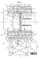
- the exchanger 1 shown in the figures comprises a shell, or envelope, 10 which delimits an enclosure inside which is fixedly mounted a double tubular bundle 2, which consists of two bundles of coaxial tubes placed end to end, of which one (2a) acts as a primary exchanger and the other (2b) as a secondary exchanger.
- This enclosure has approximately a generally cylindrical shape, of horizontal axis X-X ' .
- the beam 2a consists of a group of five adjacent tubes forming a helical winding, of axis X-X ', while the other beam 2b consists of two adjacent tubes, also helically wound, and of axis X- X '.
- the five tubes forming the bundle 2a and the two tubes forming the bundle 2b are identical, of the same length and of the same diameter.
- the beam 2a therefore has an axial dimension two and a half times greater than that of the beam 2b.
- Bosses (not shown) provided on the large faces of the tubes act as spacers, to delimit between each turn a gap of calibrated value, substantially constant.
- Each primary beam 2a and secondary 2b is intended to be traversed internally by at least one fluid to be heated, which is for example water.
- the two helical tubes of the secondary beam 2b are connected in series, the fluid to be heated being a single fluid, for example sanitary water, which flows from the left to the right when the we look at figures 1 and 2 .
- This fluid is hereinafter referred to as "secondary fluid" with reference to the beam in which it flows.
- the five helical tubes of the primary beam 2a (referenced 210, 220, 230, 240 and 250) are respectively connected in a group of two and in a group of three in parallel, and the two groups are connected in parallel. series, the fluid to be heated being a single fluid, for example water for heating premises. The fluid also flows from left to right if we consider the figures 1 and 2 . It is hereinafter referred to as "primary fluid".
- Lateral collectors 5 and 5 ' which are fixed to the casing 10, allow the connection of the apparatus, conventionally, respectively to two primary and secondary fluid supply ducts, cold, to be heated and on two ducts. evacuation of these same heated fluids.
- Each tube or tubular element has straight end portions, that is to say rectilinear axis, and of progressively variable section, whose opening end portion is circular.
- the inlet and outlet mouths of the tubular elements are crimped appropriately, and sealingly, in appropriate openings provided in the casing 10, to open into the collectors 5, 5 '.
- the inlet-outlet manifold 5 comprises four adjacent chambers separated by three internal partitions 51, 53 and 55, namely an inlet chamber 50 of the secondary fluid provided with a nozzle 500, an outlet chamber 52 of the secondary fluid. equipped with a nozzle 520, an inlet chamber 54 of the primary fluid provided with a nozzle 540 and an outlet chamber 56 of this primary fluid provided with a nozzle 560.
- the ends 500 and 520 are intended to be connected to a supply pipe 91 of the secondary fluid to be heated and, respectively, a discharge pipe 92 of the heated secondary fluid.
- the end pieces 540 and 560 are intended to be connected to a feed pipe 93 of the primary fluid to be heated and, respectively, a discharge pipe 94 of the heated primary fluid.
- the chamber 50 is connected to the inlet end portion 27'b of the tube 270 and the chamber 52 to the outlet end portion 26'b of the tube 260 of the bundle 2b.
- the chamber 54 is connected to the input end portions 24'a and 25'a of the two tubes 240 and 250 of the primary beam 2a, into which the primary fluid to be heated enters; the chamber 56 is connected to the outlet end portions 21'a, 22'a and 23'a of the three tubes 210, 220 and 230 of the primary beam 2a, through which the heated primary fluid exits.
- the opposite manifold 5 has two transfer chambers 57 and 59 separated by a partition 58.
- the transfer chamber 57 is connected to both the output end portion 27b and the input end portion 26b of the two elements of the secondary bundle 2b, 2a, and the transfer chamber 59 is connected to both the end portions of the output 24a and 25a of the tubes 240 and 250 of the primary beam 2a and the input end portions 21a, 22a and 23a of the three tubular elements 210, 220 and 230 of the beam 2a.
- the primary flow (arrows Ea) entering through the nozzle 540 is subdivided into two streams, each of which travels one winding (tube) 240, 250, meet in the chamber 59 and are transferred (arrows Ta) into the other three tubes 210, 220 and 230 to open (arrows Sa) in the chamber 56 and out through the tip 560.
- the circulation of this primary fluid is done for example by means of a pump 9.
- the incoming secondary flow (arrow Eb) enters via the nozzle 500, passes through the tube winding 270, then is transferred (arrow Tb) through the chamber 57 in the neighboring winding 260 to open (arrow Sb ) in the chamber 52 and out of the mouthpiece 520.
- the envelope 10, like the (or) tube (s) 210 to 270, may be metal, especially stainless steel.
- It is for example manufactured by roto-molding or by injection molding.
- the envelope is made for example of two half-shells which are heat-welded to each other after the tubular bundles have been installed inside one of them.
- the envelope 10 is open at its two ends, located on the right and on the left, if we consider the view of figures 1 and 2 .
- the opening formed in the front wall 14 of the casing 10 bears the reference 11 and that formed in the rear wall 15, the reference 12.
- part of the water vapor contained in the flue gases condenses on contact with the walls of the tubes 210 to 270.
- Reference 13 designates the bottom wall of the envelope 10; in known manner, this bottom is sloped, which allows the evacuation of condensate to an outlet (bonde) 130.
- the opening 12 is connected to an exhaust duct 122 of the cooled gases.
- the orifice 130 is connected to a condensate discharge conduit, while the sleeve 122 is connected to a flue gas discharge duct, for example a chimney flue.
- a flue gas discharge duct for example a chimney flue.
- the two roles hitherto devolved on the envelope are dissociated, namely, on the one hand, serving as an enclosure for the circulation and evacuation of hot gases, as well as for the collection and evacuation of condensates, and on the other hand, ensure the mechanical strength of the tube bundle.
- the bundles of tubes are preferably surrounded by a shell 16 forming a heat shield, to prevent the casing 10 from being directly exposed to the hot gases, in a similar arrangement to that described in the document FR 2,850,451 .
- the opening 11 on the front side of the envelope is closed by a front element 3, shown only in dotted lines, for simplification purposes.
- this facade element is attached to the envelope hermetically to the gases.
- a removable door provided with a central opening, through which a burner 4, for example a gas burner (or even fuel).
- the burner 4 is secured to the door.
- the door can also be made to present the structure described in the French patent application no. 09 51422 of March 6, 2009 , to which we can refer.
- the door comprises a pair of metal sheets, secured to one another at their periphery, the internal sheet being provided with an opening in which a burner is arranged and the outer sheet being connected to a control system. supplying a fuel gas to said burner.
- a baffle plate including itself two spaced walls and acting heat shield is inserted in the space between the two sheets of the door, to limit heat loss through the door and avoid the risk of burns at the door. contact with it, especially during maintenance work on the device by specialized personnel.
- Appropriate means connected to the burner 4 allow to bring to the apparatus, via a conduit, a mixture of gas and air fuel, such as propane and air in particular.
- These means may comprise a fan, not shown, capable of blowing the gas mixture into the burner.
- the burner 4 is a cylindrical tube with a closed end, whose wall is pierced with a multitude of small holes which allow the passage of the fuel mixture, radially from the inside to the outside of the tube.
- the outer surface of this wall constitutes the combustion surface.
- An ignition system of known type for example comprising a spark generator electrode, is obviously associated with the burner.
- this first part 200a thus comprises three windings of tubes 210, 220 and 230.
- the burner 4 could of course be replaced by a flat burner whose combustion surface would be perpendicular to the axis X-X 'or slightly curved.
- the interior space of the first part 200a of the tube bundle 2a is closed at its front end by the front element 3 and the door associated therewith and at its front end by a deflector plate 61 .
- This deflector plate 61 is constituted by a disc made of insulating material and refractory to heat, for example based on ceramic; it is supported by a discoid reinforcement in the form of a thin plate 610, in stainless steel, of larger diameter.
- the armature 610 is fixed between the last turn of the tube 230 and the first turn of the neighboring tube 240.
- the first part 200a of the tube bundle 2a is thus trapped axially between the front wall 14 and the deflector plate 61, whose armature 610 is fixed against its last turn.
- a second deflector plate 62 preferably not thermally insulated, is fixed between the last turn of the primary beam 2a, here the last turn of the tube 250, rear side (left on the figures 1 and 2 ) and the first turn of the secondary beam 2b, here the first turn of the tube 260, front side of the exchanger.
- this second deflector plate 62 is constituted by a disc supported by a discoidal reinforcement in the form of a thin plate 620, made of stainless steel, of larger diameter.
- the secondary beam 2b is thus trapped axially between the rear wall 15 of the casing 10 and the deflector 62, whose armature 620 is fixed against its last turn.
- the first and second deflector plates are thus centered on the X-X 'axis and parallel to each other.
- the deflector plates 61 and 62 are attached to the turns in a gas-tight manner.
- a discoidal deflector ring 63 is fixed around the primary beam 2a, that is to say outside the latter and inside the envelope 10. It is formed either from a thin sheet is made of a heat-resistant plastic material and consists of two half-rings assembled for example by crimping.
- This deflector ring 63 is supported both on the small outer side of one of the turns, here the last turn (left on the figures 1 and 2 ) of the fourth tube 240 and on the inner wall of the casing 10, for example by means of some guides molded in the casing 10 and not shown in the figure for the purpose of simplification (see also FIG. figure 3 ).
- this attachment is made so as to be gas-tight, for example by using a seal, so that the annular space extending between the outside of the bundles of tubes 2a and 2b and the inner wall of the envelope 10 is split into two parts that do not communicate directly.
- second part 200'a The portion of the primary beam 2a which extends axially between the deflector 61 and the deflector ring 63 is hereinafter referred to as "second part" 200'a. In the embodiment shown, it corresponds here to the only fourth tube 240.
- third part 200 "a hereinafter referred to as "third part” 200 "a, here it corresponds to the only fifth tube 250.
- the annular ferrule 16 is locked axially between the front wall 14 of the casing 10 and the deflector ring 63.
- this ferrule is obviously adapted to allow the passage to the various open ends 21a to 24a and 21'a to 24'a which cross to join the collectors 5, 5 '.
- This shell 16 is thus positioned opposite the first and second portions 200a and 200'a of the primary beam 2a which constitute the hottest zones of the exchanger.
- the two deflector plates 61, 62 and the deflector ring 63 constitute a series of three baffles in the path of the combustion gases.
- combustion chamber 71 that extending between the two deflector plates 61 and 62, “intermediate chamber 73 “, and that extending between the plate 62 and the sleeve 122,” evacuation chamber 75 ".
- the annular zones extending outside the bundle of tubes and inside the envelope 1 are respectively referenced 72, for that located between the front partition 14 and the ring 63, and 74 for that located between the ring 63 and the rear wall 15.
- the primary fluid to be heated, cold water for example, is circulated by the pump 9.
- a combustible gas mixture symbolized by the arrow I , is fed to the burner 4.
- the burner 4 having been ignited, the hot gases (combustion products) are generated by the latter in the combustion chamber 71. They constitute the sole source of hot gases used to heat the primary fluid and the secondary fluid, as described herein. -after.
- the gases are at a temperature of the order of 950 ° C to 1000 ° C. After passing through the portion 200a, these gases undergo a first cooling to arrive in the annular zone 72 at a temperature of the order of 100 ° C to 140 ° C.
- the gases then pass axially through the zone 72 (arrows i1 ), come into contact with the deflector ring 63 and are deflected so as to traverse radially the interstices separating the turns of the tube 240 (second part 200'a of the bundle 2a), outside to inside (arrow i2 ).
- the presence of the refractory material on the deflector plate 61 makes it possible to prevent the heat transfer from the burner 4 to the intermediate chamber 73.
- a third cooling of the gases takes place when the latter cross radially the turns of the tube 250 (third part 200 "of the beam 2a), from the inside to the outside (arrow i3 ), they can not escape axially due to the presence of the deflector plate 62.
- the gases reach the annular zone 74 at a temperature always lower than 75 ° C., in view of the previous cooling. This is important as will be detailed later.
- a fourth cooling occurs during the passage of gases through the interstices separating the turns of the secondary beam 2b, from the outside to the inside (arrows i4 ).
- the temperature of the combustion gases is lowered along their path, as a result of the heat transfer between these hot gases and the fluids flowing through the beams 2a and 2b and which flow countercurrently to the path of these gases.
- the deflector plate 62 constitutes a third baffle in the path of the hot gases.
- His position is important. It must always be located between the primary beam 2a and the secondary beam 2b. It makes it possible to significantly lower the temperature of the gases arriving in zone 74 and in particular to guarantee that it will always be below 75 ° C.
- the secondary fluid for example water
- present in the beam 2b may be either stagnant or circulating. In the case where it is stagnant, the presence of the deflector plate 62 prevents this secondary fluid is raised to a very high temperature, which could lead to the damage or rupture of the tubes 260 and 270 .
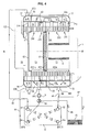
- the exchanger 1 above is used in the device for producing at least two hot fluids, according to the invention.
- Such a device is represented on the figure 2 and it comprises, in addition to the aforementioned condensing heat exchanger 1, a second exchanger 8.
- This second exchanger is for example a plate exchanger, known to those skilled in the art and which will not be described in detail.
- such an exchanger is composed of a set of superimposed parallel plates which delimit two heat exchange chambers traversed by the primary fluid and the secondary fluid, these two fluids flowing in the form of alternating thin layers. , with trajectories nested one inside the other.
- the inlet and outlet of the primary fluid is via a pair of mouths 82 and 84, respectively.
- the inlet and outlet of the secondary fluid is via a pair of mouths 81 and 83, respectively.
- mouths are formed in an end plate in the stack, via "wells", or inlet and outlet chimneys passing through the inner plates and communicating with the interstitial spaces constituting the corresponding enclosure.
- the plates of the exchanger are thin, thermally conductive metal plates, usually made of stainless steel, which are pressed and assembled by soldering or bonding by means of bolted flanges, with the interposition of rubber seals.
- the total number of plates is generally between ten and thirty for domestic power exchangers.
- the arrangement is designed so that the two streams of fluids between which the heat exchange occurs follow a labyrinth trajectory and flow against the current of each other, to promote this exchange.
- the discharge pipe 92 of the secondary fluid which has been preheated in the exchanger 1 is connected to the mouthpiece 81, while the discharge pipe 94 of the primary fluid which has been reheated in the exchanger 1 is connected to the mouthpiece 82.
- the mouth 84 is connected to the pump 9 via the feed pipe 93.
- the second heat exchanger 8 could also be a balloon intended to receive the primary fluid and through which a coil passes through which the secondary fluid circulates, or vice versa.
- the hot fluid generating device further comprises a three-way valve 99.
- This device can be connected, for example, to a central heating installation which comprises several radiators 96 (only one of which is shown in FIG. figure 2 ) or a heating slab that includes a serpentine tubing integrated into the floor.
- the radiator 96 is connected to the three-way valve 99 by a pipe 95 and the pipe 94 via a pipe 97 by a stitching or T-connection 98.
- the operation of the device is as follows.
- the pump 9 and the burner 4 are operated and the three-way valve 99 is positioned, so that the fluid primary circulates in the primary exchanger 2a, inside which it heats up to reach a certain temperature, for example 60 ° C, at the outlet of the nozzle 560, then in the radiator 96 before returning via the line 95, to the valve 99 and then back to the pump 9.
- a certain temperature for example 60 ° C
- the fluid path in the central heating circuit is represented by the arrows j.
- a drawing tap not shown in the figures makes it possible to circulate the water in the secondary circuit.
- the cold domestic water EFS enters the secondary heat exchanger 2b through the nozzle 500, circulates in the tubes 270 and 260, inside which it is heated by heat exchange with the gases present in the chambers 74 and 75, spring preheated via the discharge pipe 92, enters the exchanger 8 from which it leaves the desired temperature by the mouth 83, in the form of domestic hot water ECS.
- switching to "sanitary draw” mode causes the activation of the three-way valve 99 which passes into a position in which the return of the primary fluid from the pipe 95 is impossible.
- the primary fluid leaving the primary heat exchanger 2a is then directed to the heat exchanger 8 from which it emerges from the mouth 84 after having transmitted its heat to the secondary fluid, before returning to the pump 9.
- the heat exchanger 1 according to the invention and the device for producing hot fluid which includes it have particularly high performance compared to known devices of the prior art.
- the yield is in this case of the order of 96% to 97%.
- the outlet temperature of the fumes is conditioned by the temperature of the primary fluid which remains high, therefore, the fumes have a temperature which remains higher than the dew point which is at most 55 ° C. There is therefore no condensation in the main exchanger and no recovery of the latent heat contained in the fumes. The yield is therefore mediocre.
- the yield is in this case of the order of 107% to 109%, or even 110%, 10 to 12% higher than the state of the prior art.
- the device according to the invention makes it possible to obtain a double advantage.
- the EFS cold water that passes through the tubes 260 and 270 is at a very low temperature, of the order of 10 ° C.
- the products of combustion and fumes which pass into the interstices between these tubes are themselves themselves at a low temperature, of the order of 60 ° C. to 75 ° C. in the chamber 74, since they are at their third passage through the tubes of the primary exchanger.
- Their fourth passage through the tubes 260 and 270 containing water at 10 ° C further lowers their temperature, which explains the very good performance of the exchanger 1.
- the fact that the secondary fluid is preheated in the exchanger 1 reduces the amount of energy required to bring it to its final temperature.
- FIG. figure 4 A first variant embodiment of the condensing heat exchanger is shown in FIG. figure 4 .
- This exchanger differs from the previous in that the secondary heat exchanger 2a comprises only one tube 270 instead of two.
- the transfer chamber 57 is provided with a nozzle 570 which is connected to the discharge pipe 2 and the chamber 52 does not exist.
- FIG. figure 5 A second embodiment variant of the condensing heat exchanger is shown in FIG. figure 5 .
- first part 200a of the primary beam comprises only two tubes instead of three.
- the number of tubes of the different parts of the primary heat exchanger and the secondary heat exchanger can be adapted according to the needs of the user, provided that the plurality of deflector plates and the deflector ring which allow to cool the gases to the desired temperature.
- the hot gas present in the combustion chamber 71 is not necessarily generated by a burner housed in the primary beam. It can come from an external source and be conveyed inside the primary beam by means of a duct connected axially to the partition 3 and which then constitutes a means of supplying these gases.
- the device according to the invention could be used to heat other fluids, such as oil for example.
- the dimensions of the device governed in particular by the section, the diameter, and the length of the tubular bundles, as well as - where appropriate - by the type of burner implemented will of course be adapted to the desired power and conditions of use.
- the device may advantageously be equipped with a temperature probe adapted to stop the admission of hot gases when the probe detects a predetermined excessive temperature.
Landscapes
- Engineering & Computer Science (AREA)
- Physics & Mathematics (AREA)
- Thermal Sciences (AREA)
- Mechanical Engineering (AREA)
- General Engineering & Computer Science (AREA)
- Chemical & Material Sciences (AREA)
- Combustion & Propulsion (AREA)
- Heat-Exchange Devices With Radiators And Conduit Assemblies (AREA)
- Instantaneous Water Boilers, Portable Hot-Water Supply Apparatuses, And Control Of Portable Hot-Water Supply Apparatuses (AREA)
- Details Of Fluid Heaters (AREA)
Description
La présente invention concerne un dispositif de production de fluides chauds, qui comprend notamment un échangeur de chaleur à condensation pour le réchauffage de plusieurs fluides et des moyens de production d'un gaz chaud, tels qu'un brûleur, en particulier à gaz ou à fioul ou des moyens d'amenée d'un gaz chaud produit préalablement par une source extérieure.The present invention relates to a device for producing hot fluids, which comprises in particular a condensing heat exchanger for heating a plurality of fluids and means for producing a hot gas, such as a burner, in particular for gas or gas. fuel oil or means for supplying a hot gas produced beforehand by an external source.
Ce dispositif est destiné notamment à équiper une chaudière à gaz pour des applications domestiques ou industrielles, par exemple en vue d'alimenter un circuit de chauffage central et/ou de fournir de l'eau à usage sanitaire.This device is intended in particular to equip a gas boiler for domestic or industrial applications, for example to supply a central heating circuit and / or to provide water for sanitary purposes.
L'échangeur de chaleur dudit dispositif est du type comprenant une enveloppe qui délimite une enceinte à l'intérieur de laquelle est logé au moins un faisceau de tube(s), comme décrit par exemple dans le document
Dans le document
Ce tube est enroulé en hélice et possède une section droite aplatie et ovale dont le grand axe est sensiblement perpendiculaire à l'axe de l'hélice, et chaque spire du tube possède des faces planes qui sont écartées des faces de la spire adjacente d'un interstice de largeur constante, cette largeur étant sensiblement plus faible que l'épaisseur de ladite section droite, l'espacement entre deux spires voisines étant en outre calibré au moyen d'entretoises, lesquelles sont constituées par des bossages formés dans la paroi du tube.This tube is helically wound and has a flattened and oval cross-section whose major axis is substantially perpendicular to the axis of the helix, and each turn of the tube has plane faces which are spaced from the faces of the adjacent turn of the tube. a gap of constant width, this width being substantially smaller than the thickness of said cross section, the spacing between two adjacent turns being further calibrated by means of spacers, which consist of bosses formed in the wall of the tube; .
Ce document décrit également des échangeurs de chaleur comportant plusieurs éléments tels que décrits ci-dessus, qui sont agencés de différentes manières dans les divers modes de réalisation exposés.This document also describes heat exchangers comprising several elements as described above, which are arranged in different ways in the various embodiments disclosed.
Un élément échangeur ainsi conçu est capable d'assurer un échange de chaleur très efficace entre, d'une part, des gaz très chauds, lesquels peuvent être générés directement par un brûleur monté dans l'enceinte, ou provenir d'une source extérieure, qui lèchent l'élément tubulaire, et, d'autre part, un fluide à réchauffer, tel que de l'eau, lequel circule à l'intérieur de celui-ci.An exchanger element thus designed is capable of providing a very efficient heat exchange between, on the one hand, very hot gases, which can be generated directly by a burner mounted in the enclosure, or come from an external source, which lick the tubular element, and, secondly, a fluid to be heated, such as water, which circulates inside thereof.
En effet, lors de son passage à travers l'interstice entre les spires, suivant une direction approximativement radiale, le flux de gaz chauds vient en contact avec une surface relativement étendue de la paroi de l'élément d'échangeur.Indeed, during its passage through the gap between the turns, in an approximately radial direction, the flow of hot gas comes into contact with a relatively large area of the wall of the exchanger element.
La figure 20 du document
Un tel échangeur permet, grâce aux deux chicanes formées par le disque et l'obturateur, de faire circuler les gaz chauds successivement de l'intérieur du faisceau primaire vers l'extérieur, puis en aval du disque et en amont de l'obturateur de l'extérieur vers l'intérieur, puis enfin de les faire s'échapper par la manchette d'évacuation des gaz refroidis.Such an exchanger makes it possible, thanks to the two baffles formed by the disk and the shutter, to circulate the hot gases successively from the inside of the primary beam outwards, then downstream of the disk and upstream of the shutter of the outside to the inside, then finally to escape through the exhaust duct cooled gases.
Toutefois, dans le document précité, il n'est prévu de réchauffer qu'un seul fluide à l'aide d'une seule source de chaleur. Or, dans certaines applications, il peut être utile de réchauffer aux moins deux fluides, par exemple de l'eau à usage sanitaire et de l'eau pour un circuit de chauffage d'un bâtiment.However, in the aforementioned document, it is intended to heat a single fluid with a single source of heat. However, in some applications, it may be useful to heat at least two fluids, for example water for sanitary use and water for a heating circuit of a building.
L'échangeur de chaleur à condensation, décrit dans le document
Toutefois, il est conçu pour récupérer la chaleur d'un gaz chaud additionnel provenant d'une seconde source de chaleur, par exemple de l'échappement d'un moteur. La récupération des calories présentes dans ces gaz d'échappement permet ainsi d'améliorer le rendement global de l'échangeur de chaleur.However, it is designed to recover the heat of an additional hot gas from a second source of heat, for example the exhaust of an engine. The recovery of the calories present in these exhaust gases thus makes it possible to improve the overall efficiency of the heat exchanger.
A cet effet, il comprend une enveloppe imperméable aux gaz, à l'intérieur de laquelle sont montés un brûleur à gaz ou à fioul, et deux faisceaux de tubes coaxiaux, réalisés dans un matériau thermiquement bon conducteur, dont l'un fait office d'échangeur primaire et l'autre d'échangeur secondaire, chacun de ces faisceaux consistant en un tube, ou en un groupe de tubes disposés bout à bout et enroulés en hélice. De plus, des moyens sont prévus pour faire circuler deux fluides distincts à réchauffer, dit respectivement "primaire" et "secondaire", en particulier de l'eau froide, à l'intérieur du(des) tube(s) constitutif(s) respectivement dudit faisceau primaire et dudit faisceau secondaire.For this purpose, it comprises a gas impermeable envelope, inside which are mounted a gas or oil burner, and two bundles of coaxial tubes, made of a thermally good conducting material, one of which acts as a primary exchanger and the other secondary exchanger, each of these bundles consisting of a tube, or a group of tubes arranged end to end and helically wound. In addition, means are provided for circulating two distinct fluids to be heated, said respectively "primary" and "secondary", in particular cold water, inside the (the) tube (s) constitutive (s) respectively said primary beam and said secondary beam.
Selon une disposition spécifique de cet échangeur, deux plaques déflectrices sont intercalées entre le faisceau primaire et le faisceau secondaire et sont disposées parallèlement côte à côte, avec un certain espacement, de façon que l'une ferme une extrémité du faisceau primaire et que l'autre ferme l'extrémité adjacente du faisceau secondaire. Ces deux plaques définissent ainsi un espace à l'intérieur duquel circule un gaz chaud additionnel, amené depuis un conduit extérieur branché sur l'enveloppe.According to a specific arrangement of this exchanger, two deflector plates are interposed between the primary beam and the secondary beam and are arranged parallel side by side, with a certain spacing, so that one closes one end of the primary beam and that the another closes the adjacent end of the secondary beam. These two plates thus define a space inside which circulates an additional hot gas, brought from an external conduit connected to the envelope.
Ce gaz chaud additionnel participe ainsi au réchauffement du fluide secondaire en traversant les spires du faisceau de tubes de l'échangeur secondaire.This additional hot gas thus participates in the heating of the secondary fluid through the turns of the tube bundle of the secondary exchanger.
Toutefois, la présence de la seconde plaque déflectrice (plaque aval) ne se justifie que par le fait qu'elle délimite avec la première un espace pour recevoir le gaz chaud additionnel. Pour ce qui est du flux de gaz chaud issu du brûleur, la paire de plaques est équivalente à une plaque déflectrice unique et ce flux de gaz chauds va circuler radialement de l'intérieur vers l'extérieur du faisceau primaire au niveau du brûleur, puis axialement à l'extérieur de l'enroulement en contournant l'ensemble formé par les deux plaques et enfin, radialement de l'extérieur vers l'intérieur du faisceau secondaire, où circule le fluide secondaire.However, the presence of the second deflector plate (downstream plate) is only justified by the fact that it defines with the first a space for receiving the additional hot gas. With regard to the flow of hot gas from the burner, the pair of plates is equivalent to a single baffle plate and this flow of hot gases will flow radially from the inside to the outside of the primary beam at the burner, then axially outside the winding bypassing the assembly formed by the two plates and finally, radially from the outside to the inside of the secondary beam, where the secondary fluid circulates.
L'homme du métier n'avait donc aucune raison de chercher dans ce document
On connait, d'après le document
Toutefois, un tel échangeur ne permet absolument pas de réchauffer un fluide secondaire distinct du fluide primaire. En conséquence, il ne comprend pas d'échangeur secondaire, ni de moyens pour y faire circuler un fluide secondaire, ni de plaque déflectrice intercalée entre l'échangeur primaire et l'échangeur secondaire.However, such an exchanger absolutely does not allow to heat a secondary fluid separate from the primary fluid. Consequently, it does not include a secondary heat exchanger, nor means for circulating a secondary fluid, nor a baffle plate interposed between the primary heat exchanger and the secondary heat exchanger.
Enfin, on connait aussi d'après le document
Toutefois, ce dispositif ne comprend par un échangeur de chaleur à condensation conforme à celui de la revendication 1 et notamment ne comprend pas de plaque déflectrice positionnée entre un faisceau primaire et un faisceau secondaire.However, this device does not include a condensing heat exchanger according to that of
L'invention a donc pour objectif de fournir un dispositif de production de fluides chauds comprenant un échangeur de chaleur à condensation et dont le rendement global est amélioré.The invention therefore aims to provide a device for producing hot fluids comprising a condensing heat exchanger and whose overall efficiency is improved.
Un autre objectif de l'invention est d'augmenter ce rendement global tout en mettant en oeuvre des moyens qui grèvent peu le prix de revient de l'échangeur et n'en augmentent pas l'encombrement de façon trop importante.Another object of the invention is to increase this overall efficiency while implementing means that do little to increase the cost price of the exchanger and do not increase its size too much.
Un autre objectif encore est de fournir un dispositif facile à fabriquer en grandes séries et aisément modulable, de façon à pouvoir faire face aux différents besoins de la clientèle tant sur le plan de la capacité de transfert thermique et des quantités des différents fluides à réchauffer que sur le plan de l'encombrement.Another objective is to provide a device easy to manufacture in large series and easily scalable, so as to meet the different needs of the customer both in terms of the heat transfer capacity and the amounts of different fluids to be heated than in terms of clutter.
A cet effet, l'invention concerne un dispositif de production de fluides chauds, comprenant des moyens d'amenée ou des moyens de production de gaz chauds et un échangeur de chaleur à condensation qui comprend :
- un faisceau de tubes faisant office d'échangeur primaire, ce faisceau consistant en un tube, ou en un groupe de tubes disposés bout à bout, formant un enroulement en hélice, dans lequel la paroi du (des) tube(s) est réalisée dans un matériau thermiquement bon conducteur, ce faisceau étant monté fixement à l'intérieur d'une enveloppe imperméable aux gaz, et munie d'une manchette d'évacuation des gaz,
- une première plaque déflectrice, réalisée dans un matériau thermiquement isolant et réfractaire à la chaleur, par exemple à base de céramique, intercalée entre deux spires consécutives dudit faisceau primaire, cette première plaque déflectrice étant centrée sur l'axe de l'hélice et fermant une partie de l'espace intérieur dudit faisceau primaire,
- un anneau discoïde déflecteur disposé autour du faisceau de tubes faisant office d'échangeur primaire, en aval de ladite première plaque déflectrice par rapport au sens de circulation desdits gaz chauds, cet anneau déflecteur étant fixé à sa périphérie extérieure à ladite enveloppe et à sa périphérie intérieure à l'une des spires dudit échangeur primaire,
- une seconde plaque déflectrice centrée sur ledit axe d'hélice,
ledit dispositif de production de fluides chauds comprenant en outre des moyens pour faire circuler un fluide à réchauffer, dit "primaire", en particulier de l'eau froide, à l'intérieur du ou des tube(s) constitutif(s) du faisceau qui fait office d'échangeur primaire, la circulation de ce fluide primaire s'effectuant à contre sens de celle desdits gaz chauds.To this end, the invention relates to a device for producing hot fluids, comprising feed means or means for producing hot gases and a condensing heat exchanger which comprises:
- a bundle of tubes acting as a primary exchanger, this bundle consisting of a tube, or a group of tubes arranged end to end, forming a helical winding, in which the wall of the tube (s) is made in a thermally good conducting material, this beam being fixedly mounted inside a gas-impermeable envelope, and provided with a gas evacuation sleeve,
- a first baffle plate, made of a thermally insulating material and refractory to heat, for example based on ceramic, interposed between two consecutive turns of said primary beam, this first baffle plate being centered on the axis of the helix and closing a part of the interior space of the primary beam,
- a deflector discoid ring disposed around the bundle of tubes acting as a primary exchanger, downstream of said first deflector plate with respect to the direction of flow of said hot gases, this deflector ring being fixed at its outer periphery to said envelope and at its periphery; inside one of the turns of said primary exchanger,
- a second baffle plate centered on said propeller axis,
said device for producing hot fluids further comprising means for circulating a fluid to be heated, called "primary", in particular cold water, inside the tube (s) constituting (s) beam which acts as a primary exchanger, the circulation of this primary fluid being effected against the direction of that of said hot gases.
Conformément à l'invention, ledit échangeur de chaleur à condensation comprend un second faisceau de tubes faisant office d'échangeur secondaire, monté fixement à l'intérieur de ladite enveloppe de façon coaxiale au premier faisceau de tubes et placé au bout de celui-ci, ce second faisceau consistant également en un tube, ou en un groupe de tubes disposés bout à bout, formant un enroulement en hélice, dans lequel la paroi du (des) tube(s) est réalisée dans un matériau thermiquement bon conducteur, ladite seconde plaque déflectrice est intercalée entre le faisceau primaire et ledit faisceau secondaire, cette seconde plaque déflectrice fermant l'espace intérieur dudit faisceau secondaire, de sorte que lesdits gaz chauds traversent l'échangeur secondaire, en passant à travers les interstices séparant ses spires de l'extérieur vers l'intérieur, avant d'être enfin évacués à l'extérieur à basse température, via ladite manchette d'évacuation des gaz, et ledit dispositif de production de fluides chauds comprend des moyens pour faire circuler séparément au moins un fluide à réchauffer, dit "secondaire", distinct du fluide primaire, à l'intérieur du ou des tube(s) dudit faisceau secondaire, la circulation de ce fluide secondaire s'effectuant également à contre sens de celle desdits gaz chauds.According to the invention, said condensing heat exchanger comprises a second bundle of tubes acting as a secondary exchanger, fixedly mounted inside said casing coaxially with the first bundle of tubes and placed at the end thereof. this second beam also consisting of a tube, or a group of tubes arranged end to end, forming a spiral winding, in which the wall of the tube (s) is made of a thermally good conducting material, said second deflector plate is interposed between the primary beam and said secondary beam, this second deflector plate closing the interior space of said secondary beam, so that said hot gases pass through the secondary exchanger, passing through the interstices separating its turns from the exterior to the interior, before being finally discharged to the outside at low temperature, via said gas evacuation sleeve, and said device for producing hot fluids comprises means for circulating separately at least one fluid to be heated, said "secondary", distinct from the primary fluid, inside the tube (s) of said secondary beam, the circulation of this fluid secondary is also performed against the direction of that of said hot gases.
Selon d'autres caractéristiques avantageuses et non limitatives de l'invention, prises seules ou en combinaison :
- lesdits moyens de production de gaz chauds sont un brûleur à gaz ou à fioul ;
- ledit anneau déflecteur est fixé entre les spires du faisceau primaire et la paroi intérieure de l'enveloppe, de manière à séparer l'espace annulaire ménagé entre la face extérieure des faisceaux de tubes et l'enveloppe, en deux zones, et ce, de manière étanche aux gaz ;
- lesdites plaques déflectrices sont des disques fixés aux spires des faisceaux primaire et secondaire, de façon à obturer l'espace intérieur des faisceaux de manière étanche aux gaz ;
- l'espace intérieur de ladite première partie de l'échangeur primaire, dit "chambre de combustion", est obturé à une extrémité par la première plaque déflectrice et à son autre extrémité, par une façade munie d'une porte traversée par lesdits moyens d'amenée ou de production de gaz chauds ;
- l'espace intérieur du faisceau de qui fait office d'échangeur secondaire, dit "chambre d'évacuation", est obturé à une extrémité par la seconde plaque déflectrice et est relié, à son autre extrémité, à ladite manchette d'évacuation des gaz refroidis ;
- les deux plaques déflectrices et l'anneau discoïde déflecteur sont disposés d'une part parallèlement les uns aux autres, et d'autre part, perpendiculairement à l'axe de l'enroulement en hélice des faisceaux de tubes ;
- la largeur de l'interstice séparant deux spires adjacentes des faisceaux de tubes faisant office d'échangeur primaire et d'échangeur secondaire est constante et notablement plus faible que l'épaisseur de la section droite des tubes constituant ces faisceaux ;
- la paroi des tubes des faisceaux présente une section droite aplatie et ovale, dont le grand axe est perpendiculaire, ou approximativement perpendiculaire, à celui de l'hélice ;
- ladite enveloppe est réalisée en matière plastique résistant à la chaleur, et ledit échangeur de chaleur comprend des moyens de contention mécanique desdits faisceaux de tubes coaxiaux suivant leur direction axiale, tels qu'un jeu de tirants disposés à l'extérieur des faisceaux, parallèlement à l'axe de l'hélice et dont les extrémités sont solidaires d'éléments d'appui s'appliquant contre les deux extrémités opposées de ces faisceaux placés bout à bout, ces moyens de contention étant aptes à absorber les efforts de poussée résultant de la pression interne des fluides qui circulent dans lesdits tubes et tend à en déformer les parois, en évitant que ces efforts ne soient transmis à l'enveloppe ;
- ladite enveloppe est réalisée en matière plastique résistant à la chaleur, et ledit échangeur de chaleur comprend une virole disposée à l'intérieur de ladite enveloppe et à l'extérieur du faisceau de tube faisant office d'échangeur primaire, sur une longueur s'étendant au moins en regard de la première partie de l'échangeur primaire, cette virole assurant une fonction d'écran thermique apte à isoler l'enveloppe de la chaleur émise par les gaz chauds ;
- le dispositif comprend un second échangeur de chaleur, monté en série avec ledit échangeur de chaleur à condensation, de sorte que d'une part, la sortie du fluide primaire de l'échangeur à condensation est connectée à l'embouchure d'entrée du circuit primaire du second échangeur et que l'embouchure de sortie du fluide primaire du second échangeur est connectée à l'entrée du fluide primaire de l'échangeur à condensation et que, d'autre part, la sortie du fluide secondaire de l'échangeur à condensation est connectée à l'embouchure d'entrée du circuit secondaire du second échangeur et l'embouchure de sortie du fluide secondaire du second échangeur soit connectée au point de puisage dudit fluide secondaire, le fluide primaire chaud circulant à l'intérieur dudit second échangeur à contre-courant du fluide secondaire préchauffé dans l'échangeur à condensation ;
- le second échangeur est un échangeur à plaques ;
- le dispositif comprend une vanne à trois voies dont la première voie est connectée à l'embouchure de sortie du fluide primaire du second échangeur et la deuxième voie aux moyens de circulation eux-mêmes connectés à l'entrée du circuit primaire de l'échangeur à condensation, et il comprend également un raccord en T dont deux branches sont connectées respectivement à la sortie du fluide primaire de l'échangeur à condensation et à l'embouchure d'entrée du circuit primaire du second échangeur, la troisième voie de la vanne et la troisième branche du raccord en T étant aptes à être raccordées aux deux extrémités d'un réseau de circulation d'eau de chauffage, par exemple de chauffage central.
- said hot gas production means is a gas or oil burner;
- said deflector ring is fixed between the turns of the primary beam and the inner wall of the envelope, so as to separate the annular space provided between the outer face of the bundles of tubes and the envelope, in two zones, and this, in a gas-tight manner;
- said deflector plates are disks attached to the turns of the primary and secondary beams, so as to close the interior of the beams in a gas-tight manner;
- the inner space of said first part of the primary heat exchanger, called the "combustion chamber", is closed at one end by the first baffle plate and at its other end by a front provided with a door through which said baffle plate passes. supply or production of hot gases;
- the inner space of the beam which acts as a secondary exchanger, called "evacuation chamber", is closed at one end by the second deflector plate and is connected at its other end to said exhaust duct cooled;
- the two deflector plates and the deflector discoid ring are arranged on the one hand parallel to each other, and on the other hand, perpendicular to the axis of the helical winding of the tube bundles;
- the width of the gap separating two adjacent turns from the bundles of tubes acting as primary exchanger and secondary exchanger is constant and significantly lower than the thickness of the cross section of the tubes constituting these bundles;
- the wall of the tubes of the bundles has a flattened and oval cross-section, the long axis of which is perpendicular or approximately perpendicular to that of the helix;
- said casing is made of heat resistant plastic material, and said heat exchanger comprises means for mechanically retaining said bundles of coaxial tubes in their axial direction, such as a set of tie rods arranged outside the bundles, parallel to the axis of the propeller and whose ends are integral with support elements applying against the two opposite ends of these bundles placed end to end, these restraining means being able to absorb the thrust forces resulting from the internal pressure of the fluids circulating in said tubes and tends to deform the walls, avoiding that these efforts are transmitted to the envelope;
- said casing is made of heat resistant plastic material, and said heat exchanger comprises a ferrule disposed inside said casing and outside the tube bundle acting as a primary exchanger, over a length extending at least next to the first part of the primary heat exchanger, this ferrule providing a heat shield function capable of isolating the envelope from the heat emitted by the hot gases;
- the device comprises a second heat exchanger, connected in series with said condensing heat exchanger, so that on the one hand, the output of the primary fluid of the condensing heat exchanger is connected to the inlet mouth of the circuit of the second heat exchanger and that the outlet mouth of the primary fluid of the second heat exchanger is connected to the inlet of the primary fluid of the condensation heat exchanger and that, on the other hand, the output of the secondary fluid of the heat exchanger. condensation is connected to the inlet mouth of the secondary circuit of the second exchanger and the outlet mouth of the secondary fluid of the second exchanger is connected to the point of drawing of said secondary fluid, the hot primary fluid circulating inside said second exchanger against the current of the secondary fluid preheated in the condensation exchanger;
- the second heat exchanger is a plate heat exchanger;
- the device comprises a three-way valve whose first channel is connected to the outlet mouth of the primary fluid of the second heat exchanger and the second channel to the circulation means themselves connected to the inlet of the primary circuit of the heat exchanger. condensation, and it also comprises a T-connector whose two branches are respectively connected to the output of the primary fluid of the condenser heat exchanger and to the inlet mouth of the primary circuit of the second heat exchanger, the third channel of the valve and the third branch of the T-fitting being able to be connected to both ends of a heating water circulation network, for example central heating.
D'autres caractéristiques et avantages de l'invention apparaîtront de la description qui va maintenant en être faite, en référence aux dessins annexés, qui en représentent, à titre indicatif mais non limitatif, plusieurs modes de réalisation possibles.Other features and advantages of the invention will appear from the description which will now be made, with reference to the accompanying drawings, which show, by way of indication but not limitation, several possible embodiments.
Sur ces dessins :
- la
figure 1 est une vue de face schématique d'un premier mode de réalisation de l'échangeur à condensation et du brûleur à gaz du dispositif faisant l'objet de l'invention, coupés selon un plan vertical médian référencé I-I sur lafigure 3 ; - la
figure 2 est une vue schématique du dispositif de chauffage de plusieurs fluides faisant l'objet de l'invention qui inclut une vue de face l'échangeur de lafigure 1 , coupé selon un plan brisé référencé II-II sur lafigure 3 ; - la
figure 3 est une vue de côté de l'échangeur, coupé par le plan brisé référencé III-III sur lafigure 2 ; - les
figures 4 et 5 sont des vues analogues à lafigure 2 , mais qui représentent respectivement un deuxième et un troisième mode de réalisation de l'échangeur à condensation.
- the
figure 1 is a diagrammatic front view of a first embodiment of the condenser heat exchanger and the gas burner of the device forming the subject of the invention, cut along a median vertical plane referenced II on thefigure 3 ; - the
figure 2 is a schematic view of the heating device of several fluids forming the subject of the invention which includes a front view of the exchanger of thefigure 1 , cut according to a broken plane referenced II-II on thefigure 3 ; - the
figure 3 is a side view of the exchanger, cut by the broken plane referenced III-III on thefigure 2 ; - the
figures 4 and5 are similar views to thefigure 2 , but which respectively represent a second and a third embodiment of the condenser heat exchanger.
L'échangeur 1 représenté sur les figures comporte une coque, ou enveloppe, 10 qui délimite une enceinte à l'intérieur de laquelle est monté fixement un double faisceau tubulaire 2, lequel consiste en deux faisceaux de tubes coaxiaux placés bout à bout, dont l'un (2a) fait office d'échangeur primaire et l'autre (2b) d'échangeur secondaire.The
Cette enceinte a approximativement une forme générale cylindrique, d'axe horizontal X-X'.This enclosure has approximately a generally cylindrical shape, of horizontal axis X-X ' .
Dans le mode de réalisation représenté sur les
Les cinq tubes formant le faisceau 2a et les deux tubes formant le faisceau 2b sont identiques, de même longueur et de même diamètre. Le faisceau 2a a donc une dimension axiale deux fois et demie supérieure à celle du faisceau 2b.The five tubes forming the
Il s'agit de tubes de section droite aplatie dont les grands côtés sont perpendiculaires à l'axe X-X'. They are straight flattened tubes whose long sides are perpendicular to the X-X ' axis .
Des bossages (non représentés) prévus sur les grandes faces des tubes jouent le rôle d'entretoises, permettant de délimiter entre chaque spire un interstice de valeur calibrée, sensiblement constante.Bosses (not shown) provided on the large faces of the tubes act as spacers, to delimit between each turn a gap of calibrated value, substantially constant.
Chaque faisceau primaire 2a et secondaire 2b est destiné à être traversé intérieurement par au moins un fluide à réchauffer, qui est par exemple de l'eau.Each
Dans le mode de réalisation illustré sur la
Par ailleurs, les cinq tubes hélicoïdaux du faisceau primaire 2a, (référencés 210, 220, 230, 240 et 250), sont branchés respectivement en un groupe de deux et en un groupe de trois en parallèle, et les deux groupes sont branchées en série, le fluide à réchauffer étant un fluide unique, par exemple de l'eau destinée au chauffage de locaux. Le fluide circule également de la gauche vers la droite si on considère les
Des collecteurs latéraux 5 et 5', qui sont fixés à l'enveloppe 10, permettent le branchement de l'appareil, de manière classique, respectivement sur deux conduits d'amenée des fluides primaire et secondaire, froids, à réchauffer et sur deux conduits d'évacuation de ces mêmes fluides réchauffés.
Ces collecteurs permettent également le transfert de ces fluides d'un tube au suivant. Ils sont visibles uniquement sur les
Chaque tube ou élément tubulaire possède des portions d'extrémité droite, c'est-à-dire d'axe rectiligne, et de section progressivement variable, dont la partie d'extrémité débouchante est circulaire.Each tube or tubular element has straight end portions, that is to say rectilinear axis, and of progressively variable section, whose opening end portion is circular.
Ces parties d'extrémité débouchantes sont référencées respectivement 21a à 25a et 21'a à 25'a pour les tubes du faisceau primaire 2a et 26b, 27b, 26'b et 27'b pour les tubes du faisceau secondaire 2b.These emergent end portions are respectively referenced 21a to 25a and 21'a to 25'a for the tubes of the
Les portions d'extrémité rectilignes d'entrée et de sortie de chaque tube sont parallèles et s'étendent dans un même plan vertical, tangent à l'enroulement (voir
Les embouchures d'entrée et de sortie des éléments tubulaires sont serties convenablement, et de manière étanche, dans des ouvertures appropriées prévues dans l'enveloppe 10, pour déboucher à l'intérieur des collecteurs 5, 5'.The inlet and outlet mouths of the tubular elements are crimped appropriately, and sealingly, in appropriate openings provided in the
Le collecteur d'entrée-sortie 5' comprend quatre chambres adjacentes séparées par trois cloisons internes 51, 53 et 55, à savoir une chambre d'entrée 50 du fluide secondaire munie d'un embout 500, une chambre de sortie 52 du fluide secondaire munie d'un embout 520, une chambre d'entrée 54 du fluide primaire munie d'un embout 540 et une chambre de sortie 56 de ce fluide primaire munie d'un embout 560.The inlet-outlet manifold 5 'comprises four adjacent chambers separated by three
Les embouts 500 et 520 sont destinés à être raccordés sur un tuyau d'amenée 91 du fluide secondaire à réchauffer et, respectivement, un tuyau d'évacuation 92 du fluide secondaire réchauffé.The ends 500 and 520 are intended to be connected to a
Les embouts 540 et 560 sont destinés à être raccordés sur un tuyau d'amenée 93 du fluide primaire à réchauffer et, respectivement, un tuyau d'évacuation 94 du fluide primaire réchauffé.The
La chambre 50 est connectée à la portion d'extrémité d'entrée 27'b du tube 270 et la chambre 52 à la portion d'extrémité de sortie 26'b du tube 260 du faisceau 2b.The
La chambre 54 est connectée aux portions d'extrémité d'entrée 24'a et 25'a des deux tubes 240 et 250 du faisceau primaire 2a, dans lesquelles rentre le fluide primaire à réchauffer ; la chambre 56 est connectée aux portions d'extrémité de sortie 21'a, 22'a et 23'a des trois tubes 210, 220 et 230 du faisceau primaire 2a, par lesquelles sort le fluide primaire réchauffé.The
Le collecteur opposé 5 possède deux chambres de transfert 57 et 59, séparées par une cloison 58.The
La chambre de transfert 57 est raccordée à la fois aux portions d'extrémité de sortie 27b et d'entrée 26b des deux éléments du faisceau secondaire 2b, 2a, et la chambre de transfert 59 est raccordée à la fois aux portions d'extrémité de sortie 24a et 25a des tubes 240 et 250 du faisceau primaire 2a et aux portions d'extrémité d'entrée 21a, 22a et 23a des trois éléments tubulaires 210, 220 et 230 du faisceau 2a.The
Sur la
Le flux primaire (flèches Ea) entrant par l'embout 540 est subdivisé en deux flux qui parcourent chacun un enroulement (tube) 240, 250, se rejoignent dans la chambre 59 et sont transférés (flèches Ta) dans les trois autres tubes 210, 220 et 230 pour déboucher (flèches Sa) dans la chambre 56 et en ressortir par l'embout 560.The primary flow (arrows Ea) entering through the
La circulation de ce fluide primaire se fait par exemple au moyen d'une pompe 9.The circulation of this primary fluid is done for example by means of a pump 9.
Le flux secondaire entrant (flèche Eb) entre via l'embout 500, traverse l'enroulement de tube 270, puis est transféré (flèche Tb) par la chambre 57 dans l'enroulement voisin 260 pour déboucher (flèche Sb) dans la chambre 52 et en ressortir par l'embout 520.The incoming secondary flow (arrow Eb) enters via the
L'enveloppe 10, tout comme le (ou les) tube(s) 210 à 270, peut être en métal, notamment en acier inoxydable.The
Cependant, elle est avantageusement réalisée en matière plastique, comme cela est prévu dans les documents
Elle est par exemple fabriquée par roto-moulage ou par moulage par injection.It is for example manufactured by roto-molding or by injection molding.
L'enveloppe est faite par exemple de deux demi-coquilles qui sont thermo-soudées l'une à l'autre après que les faisceaux tubulaires aient été installés à l'intérieur de l'une d'elles.The envelope is made for example of two half-shells which are heat-welded to each other after the tubular bundles have been installed inside one of them.
L'enveloppe 10 est ouverte à ses deux extrémités, situées sur la droite et sur la gauche, si on considère la vue des
L'ouverture ménagée dans la paroi avant 14 de l'enveloppe 10 porte la référence 11 et celle ménagée dans la paroi arrière 15, la référence 12.The opening formed in the
En cours d'utilisation de l'appareil, une partie de la vapeur d'eau contenue dans les gaz brûlés se condense au contact des parois des tubes 210 à 270.During use of the apparatus, part of the water vapor contained in the flue gases condenses on contact with the walls of the
La référence 13 désigne la paroi de fond de l'enveloppe 10; de manière connue, ce fond est en pente, ce qui permet l'évacuation des condensats vers un orifice de sortie (bonde) 130.
L'ouverture 12 est raccordée à une manchette d'évacuation 122 des gaz refroidis.The
Bien entendu, l'orifice 130 est connecté à un conduit d'évacuation des condensats, tandis que la manchette 122 est branchée sur un conduit d'évacuation des fumées, par exemple un conduit de cheminée. Ces conduits ne sont pas représentés sur les figures.Of course, the
Dans l'hypothèse où l'enveloppe 10 est en matière plastique, des moyens mécaniques de contention axiale des faisceaux de tubes 2a, 2b, du genre décrit dans les deux documents
Ces moyens permettent d'absorber les efforts de poussée axiale résultant de la pression interne du fluide qui circule dans les tubes et qui tend à en déformer les parois, en évitant que ces efforts ne soient transmis à l'enveloppe.These means make it possible to absorb the axial thrust forces resulting from the internal pressure of the fluid which circulates in the tubes and which tends to deform the walls, by preventing these forces from being transmitted to the envelope.
On dissocie ainsi les deux rôles jusqu'ici dévolus à l'enveloppe, à savoir d'une part, servir d'enceinte pour la circulation et l'évacuation des gaz chauds, ainsi que pour le recueil et l'évacuation des condensats, et, d'autre part, assurer la tenue mécanique du faisceau de tubes.Thus, the two roles hitherto devolved on the envelope are dissociated, namely, on the one hand, serving as an enclosure for the circulation and evacuation of hot gases, as well as for the collection and evacuation of condensates, and on the other hand, ensure the mechanical strength of the tube bundle.
Ces moyens de contention mécanique n'ont pas été représentés ici afin de ne pas alourdir inutilement les dessins.These means of mechanical restraint have not been shown here so as not to unnecessarily burden the drawings.
De plus, les faisceaux de tubes sont entourés de préférence d'une virole 16 formant écran thermique, pour éviter que l'enveloppe 10 ne soit directement exposée aux gaz chauds, selon une disposition analogue à celle décrite dans le document
La disposition de cette virole sera décrite ultérieurement.The disposition of this ferrule will be described later.
L'ouverture 11 située côté avant de l'enveloppe est obturée par un élément de façade 3, représenté uniquement en pointillés, à des fins de simplification.The
De façon connue de l'homme du métier, cet élément de façade est fixé à l'enveloppe de manière hermétique aux gaz.In a manner known to those skilled in the art, this facade element is attached to the envelope hermetically to the gases.
Il est normalement obturé par une porte amovible, munie d'une ouverture centrale, traversée par un brûleur 4, par exemple un brûleur à gaz (voire au fioul). Le brûleur 4 est solidaire de la porte.It is normally closed by a removable door, provided with a central opening, through which a
Pour la structure de la porte, on pourra se référer par exemple à celle décrite dans le document
Selon une autre variante de réalisation, la porte peut également être réalisée de façon à présenter la structure décrite dans la demande de brevet français n°
Dans ce cas, la porte comprend une paire de tôles métalliques, solidarisées l'une avec l'autre à leur périphérie, la tôle interne étant munie d'une ouverture dans laquelle est disposée un brûleur et la tôle externe étant reliée à un système d'amenée d'un gaz combustible audit brûleur. Un plateau déflecteur comprenant lui même deux parois espacées et faisant office de bouclier thermique est inséré dans l'espace ménagé entre les deux tôles de la porte, afin de limiter les déperditions de chaleur à travers la porte et d'éviter les risques de brûlures au contact de celle-ci, surtout lors d'interventions d'entretien de l'appareil par le personnel spécialisé.In this case, the door comprises a pair of metal sheets, secured to one another at their periphery, the internal sheet being provided with an opening in which a burner is arranged and the outer sheet being connected to a control system. supplying a fuel gas to said burner. A baffle plate including itself two spaced walls and acting heat shield is inserted in the space between the two sheets of the door, to limit heat loss through the door and avoid the risk of burns at the door. contact with it, especially during maintenance work on the device by specialized personnel.
Des moyens appropriés raccordés sur le brûleur 4 permettent d'amener à l'appareil, via un conduit, un mélange de combustible gaz et air, tel que propane et air notamment.Appropriate means connected to the
Ces moyens peuvent comprendre un ventilateur, non représenté, apte à insuffler le mélange gazeux dans le brûleur.These means may comprise a fan, not shown, capable of blowing the gas mixture into the burner.
Le brûleur 4 est un tube cylindrique à extrémité fermée, dont la paroi est percée d'une multitude de petits trous qui permettent le passage du mélange combustible, radialement de l'intérieur vers l'extérieur du tube.The
La surface extérieure de cette paroi constitue la surface de combustion.The outer surface of this wall constitutes the combustion surface.
Un système d'allumage de type connu, non représenté, comportant par exemple une électrode génératrice d'une étincelle, est bien évidement associé au brûleur.An ignition system of known type, not shown, for example comprising a spark generator electrode, is obviously associated with the burner.
Ce dernier est positionné coaxialement au milieu de l'enroulement du faisceau 2a faisant office d'échangeur primaire, mais il ne s'étend pas sur toute sa longueur. Il se situe seulement à l'intérieur d'une partie de ce faisceau 2a, dénommée ci-après "première partie de l'échangeur primaire, référencée 200a. Dans l'exemple de réalisation représenté sur les
Bien que cela ne soit pas représenté sur les figures, le brûleur 4 pourrait bien entendu être remplacé par un brûleur plat dont la surface de combustion serait perpendiculaire à l'axe X-X' ou bien légèrement bombée.Although this is not shown in the figures, the
Conformément à l'invention, l'espace intérieur de la première partie 200a du faisceau de tubes 2a est obturé à son extrémité avant par l'élément de façade 3 et la porte qui lui est associée et à son extrémité avant par une plaque déflectrice 61.According to the invention, the interior space of the
Cette plaque déflectrice 61 est constituée par un disque en matériau isolant et réfractaire à la chaleur, par exemple à base de céramique ; il est supporté par une armature discoïde en forme de plaque mince 610, en acier inoxydable, de plus grand diamètre.This
L'armature 610 est fixée entre la dernière spire du tube 230 et la première spire du tube voisin 240.The
La première partie 200a du faisceau de tube 2a est ainsi emprisonnée axialement entre la paroi avant 14 et la plaque déflectrice 61, dont l'armature 610 est fixée contre sa dernière spire.The
Une seconde plaque déflectrice 62, de préférence non isolée thermiquement, est fixée entre la dernière spire du faisceau primaire 2a, ici la dernière spire du tube 250, coté arrière (à gauche sur les
De façon similaire, cette seconde plaque déflectrice 62 est constituée par un disque supporté par une armature discoïde en forme de plaque mince 620, en acier inoxydable, de plus grand diamètre.Similarly, this
Bien que cela ne soit pas représenté, elle pourrait également être constituée d'un matériau isolant et réfractaire à la chaleur.Although it is not shown, it could also be made of an insulating material and refractory to heat.
Le faisceau secondaire 2b est ainsi emprisonné axialement entre la paroi arrière 15 de l'enveloppe 10 et le déflecteur 62, dont l'armature 620 est fixée contre sa dernière spire.The
Les première et seconde plaques déflectrices sont donc centrées sur l'axe X-X' et parallèles entre elles.The first and second deflector plates are thus centered on the X-X 'axis and parallel to each other.
De préférence, les plaques déflectrices 61 et 62 sont fixées aux spires de manière étanche aux gaz.Preferably, the
Enfin, un anneau déflecteur discoïde 63, est fixé autour du faisceau primaire 2a, c'est-à-dire à l'extérieur de celui-ci et à l'intérieur de l'enveloppe 10. Il est formé soit à partir d'une tôle mince soit dans une matière plastique résistante à la chaleur et constitué de deux demi-anneaux assemblés par exemple par sertissage.Finally, a
Il s'étend dans un plan général parallèle à celui des plaques déflectrices 61 et 62, est centré sur l'axe X-X' et est positionné axialement entre les plaques déflectrices 61 et 62.It extends in a general plane parallel to that of the
Cet anneau déflecteur 63 prend appui à la fois sur le petit côté extérieur de l'une des spires, ici la dernière spire (à gauche sur les
De préférence, cette fixation est faite de façon à être étanche aux gaz, par exemple en utilisant un joint d'étanchéité, de sorte que l'espace annulaire s'étendant entre l'extérieur des faisceaux de tubes 2a et 2b et la paroi intérieure de l'enveloppe 10 est scindé en deux parties qui ne communiquent pas directement.Preferably, this attachment is made so as to be gas-tight, for example by using a seal, so that the annular space extending between the outside of the bundles of
La portion du faisceau primaire 2a qui s'étend axialement entre le déflecteur 61 et l'anneau déflecteur 63 est dénommée ci-après "deuxième partie" 200'a. Dans le mode de réalisation représenté, elle correspond ici au seul quatrième tube 240.The portion of the
De façon similaire, la portion du faisceau primaire 2a qui s'étend axialement entre l'anneau déflecteur 63 et le déflecteur 62 est dénommée ci-après "troisième partie" 200"a, elle correspond ici au seul cinquième tube 250.Similarly, the portion of the
Comme on peut le voir sur les
La forme de cette virole est bien évidemment adaptée pour laisser le passage aux différentes extrémités débouchantes 21a à 24a et 21'a à 24'a qui la traversent pour rejoindre les collecteurs 5, 5'.The shape of this ferrule is obviously adapted to allow the passage to the various
Cette virole 16 est ainsi positionnée en regard des première et deuxième parties 200a et 200'a du faisceau primaire 2a qui constituent les zones les plus chaudes de l'échangeur.This
Les deux plaques déflectrices 61, 62 et l'anneau déflecteur 63 constituent une série de trois chicanes sur le trajet des gaz de combustion.The two
A l'intérieur de l'enroulement de tubes, l'espace contenant le brûleur 4 sera dénommé dans la suite de la description, "chambre de combustion 71 ", celui s'étendant entre les deux plaques déflectrices 61 et 62, "chambre intermédiaire 73", et celui s'étendant entre la plaque 62 et la manchette 122, "chambre d'évacuation 75".Inside the winding of tubes, the space containing the
Les zones annulaires s'étendant à l'extérieur du faisceau de tubes et à l'intérieur de l'enveloppe 1 sont référencées respectivement 72, pour celle située entre la cloison avant 14 et l'anneau 63, et 74 pour celle située entre l'anneau 63 et la cloison arrière 15.The annular zones extending outside the bundle of tubes and inside the
En référence notamment aux
Le fluide primaire à réchauffer, de l'eau froide par exemple, est mis en circulation par la pompe 9.The primary fluid to be heated, cold water for example, is circulated by the pump 9.
Un mélange gazeux combustible, symbolisé par la flèche I, est amené au brûleur 4.A combustible gas mixture, symbolized by the arrow I , is fed to the
Le brûleur 4 ayant été allumé, les gaz chauds (produits de combustion) sont générés par ce dernier dans la chambre de combustion 71. Ils constituent l'unique source de gaz chauds utilisée pour réchauffer le fluide primaire et le fluide secondaire, comme décrit ci-après.The
Ces gaz traversent tout d'abord radialement la première partie 200a du faisceau primaire 2a, en passant entre les interstices séparant les spires des tubes 210, 220 et 230, de l'intérieur vers l'extérieur (flèches i) ; ils ne peuvent pas s'échapper axialement en raison de la présence de la plaque déflectrice 61.These gases first radially cross the
Dans la chambre de combustion 71, les gaz sont à une température de l'ordre de 950°C à 1000°C. Après passage au travers de la partie 200a, ces gaz subissent un premier refroidissement pour arriver dans la zone annulaire 72 à une température de l'ordre de 100°C à 140°C.In the
Les gaz traversent alors axialement la zone 72 (flèches i1), arrivent au contact de l'anneau déflecteur 63 et sont déviés de façon à traverser radialement les interstices séparant les spires du tube 240 (deuxième partie 200'a du faisceau 2a), de l'extérieur vers l'intérieur (flèche i2).The gases then pass axially through the zone 72 (arrows i1 ), come into contact with the
Ils parviennent dans la chambre intermédiaire 73 à une température de l'ordre de 85°C à 90°C.They reach the
La présence du matériau réfractaire sur la plaque déflectrice 61 permet d'empêcher la transmission de chaleur du brûleur 4 à la chambre intermédiaire 73.The presence of the refractory material on the
Un troisième refroidissement des gaz s'opère lorsque ces derniers traversent radialement les spires du tube 250 (troisième partie 200"a du faisceau 2a), de l'intérieur vers l'extérieur (flèche i3), ils ne peuvent pas s'échapper axialement en raison de la présence de la plaque déflectrice 62.A third cooling of the gases takes place when the latter cross radially the turns of the tube 250 (third part 200 "of the
Les gaz parviennent dans la zone annulaire 74 a une température toujours inférieure à 75°C, compte tenu des refroidissement précédents. Ceci est important comme cela sera détaillé ultérieurement.The gases reach the
Un quatrième refroidissement s'opère lors du passage des gaz au travers des interstices séparant les spires du faisceau secondaire 2b, de l'extérieur vers l'intérieur (flèches i4).A fourth cooling occurs during the passage of gases through the interstices separating the turns of the
Ces gaz atteignent la chambre d'évacuation 75 où ils sont à une température comprise entre 15°C et 35°C environ, voire même entre 15°C et 25°C. Enfin, ils sont évacués par la manchette 122.These gases reach the
La température des gaz de combustion est abaissée tout au long de leur trajet, par suite du transfert thermique intervenu entre ces gaz chauds et les fluides parcourant les faisceaux 2a et 2b et qui circulent à contre-courant du trajet de ces gaz.The temperature of the combustion gases is lowered along their path, as a result of the heat transfer between these hot gases and the fluids flowing through the
La plaque déflectrice 62 constitue une troisième chicane sur le trajet des gaz chauds.The
Sa position est importante. Elle doit toujours être située entre le faisceau primaire 2a et le faisceau secondaire 2b. Elle permet d'abaisser significativement la température des gaz parvenant dans la zone 74 et notamment de garantir que celle-ci sera toujours inférieure à 75°C.His position is important. It must always be located between the
Le fluide secondaire, par exemple l'eau, présent dans le faisceau 2b peut être soit stagnant, soit en circulation. Dans le cas où il est stagnant, la présence de la plaque déflectrice 62 permet d'éviter que ce fluide secondaire ne soit porté à très haute température, ce qui risquerait de conduire à l'endommagement, voire à la rupture des tubes 260 et 270.The secondary fluid, for example water, present in the
En outre, dans le cas où ce fluide secondaire est de l'eau sanitaire, ceci permet d'éviter la formation de calcaire dans les tubes du faisceau secondaire 2b.In addition, in the case where the secondary fluid is sanitary water, this prevents the formation of limestone in the tubes of the
L'échangeur 1 précité est utilisé dans le dispositif de production d'au moins deux fluides chauds, conforme à l'invention.The
Un tel dispositif est représenté sur la
Ce second échangeur est par exemple un échangeur à plaques, connu de l'homme du métier et qui ne sera donc pas décrit en détails.This second exchanger is for example a plate exchanger, known to those skilled in the art and which will not be described in detail.
Brièvement, un tel échangeur est composé d'un ensemble de plaques parallèles superposées qui délimitent deux enceintes d'échange thermique parcourues l'une par le fluide primaire et l'autre par le fluide secondaire, ces deux fluides circulant sous forme de couches minces alternées, avec des trajectoires imbriquées l'une dans l'autre.Briefly, such an exchanger is composed of a set of superimposed parallel plates which delimit two heat exchange chambers traversed by the primary fluid and the secondary fluid, these two fluids flowing in the form of alternating thin layers. , with trajectories nested one inside the other.
L'entrée et la sortie du fluide primaire se fait par une paire d'embouchures 82, respectivement 84. De façon similaire, l'entrée et la sortie du fluide secondaire se fait par une paire d'embouchures 81, respectivement 83.The inlet and outlet of the primary fluid is via a pair of
Ces embouchures sont ménagées dans une plaque d'extrémité dans l'empilage, via des "puits", ou cheminées d'entrée et de sortie traversant les plaques internes et communiquant avec les espaces interstitiels constitutifs de l'enceinte correspondante.These mouths are formed in an end plate in the stack, via "wells", or inlet and outlet chimneys passing through the inner plates and communicating with the interstitial spaces constituting the corresponding enclosure.
Les plaques de l'échangeur sont des plaques minces en métal, thermiquement bon conducteur, généralement en acier inoxydable, qui sont embouties et assemblées par brasage ou par une liaison au moyen de brides boulonnées, avec interposition de joints en caoutchouc.The plates of the exchanger are thin, thermally conductive metal plates, usually made of stainless steel, which are pressed and assembled by soldering or bonding by means of bolted flanges, with the interposition of rubber seals.
Le nombre total de plaques est généralement compris entre dix et trente pour des échangeurs de puissance domestique.The total number of plates is generally between ten and thirty for domestic power exchangers.
L'agencement est conçu pour que les deux flux de fluides entre lesquels intervient l'échange thermique suivent une trajectoire en labyrinthe et circulent à contre-courant l'un de l'autre, afin de favoriser cet échange.The arrangement is designed so that the two streams of fluids between which the heat exchange occurs follow a labyrinth trajectory and flow against the current of each other, to promote this exchange.
Le tuyau d'évacuation 92 du fluide secondaire qui a été préchauffé dans l'échangeur 1 est connecté à l'embouchure 81, tandis que le tuyau d'évacuation 94 du fluide primaire qui a été réchauffé dans l'échangeur 1 est connecté à l'embouchure 82.The
En outre, l'embouchure 84 est connectée à la pompe 9 via le tuyau d'amenée 93.In addition, the
Selon une variante de réalisation non représentée, le second échangeur 8 pourrait également être un ballon destiné à recevoir le fluide primaire et traversé par un serpentin à l'intérieur duquel circule le fluide secondaire, ou l'inverse.According to an alternative embodiment not shown, the
Le dispositif de production de fluides chauds comprend en outre une vanne à trois voies 99.The hot fluid generating device further comprises a three-
Ce dispositif peut être raccordé par exemple à une installation de chauffage central qui comprend plusieurs radiateurs 96 (dont un seul est représenté sur la
Dans l'exemple représenté, le radiateur 96 est raccordé à la vanne à trois voies 99 par une canalisation 95 et au tuyau 94 via une canalisation 97 par un piquage ou raccord en T 98.In the example shown, the
Le fonctionnement du dispositif est le suivant.The operation of the device is as follows.
En mode "chauffage du fluide primaire", par exemple pour alimenter les radiateurs 96 en vue du chauffage d'un local, on fait fonctionner la pompe 9 et le brûleur 4 et on positionne la vanne à trois voies 99, de façon que le fluide primaire circule dans l'échangeur primaire 2a, à l'intérieur duquel il se réchauffe jusqu'à atteindre une certaine température, par exemple de 60°C, à la sortie de l'embout 560, puis dans le radiateur 96 avant de retourner via la canalisation 95, à la vanne 99 puis de nouveau à la pompe 9.In "primary fluid heating" mode, for example for supplying the
Le trajet du fluide dans le circuit de chauffage central est représenté par les flèches j.The fluid path in the central heating circuit is represented by the arrows j.
En mode "puisage sanitaire", un robinet de puisage non représenté sur les figures permet de faire circuler l'eau dans le circuit secondaire. L'eau froide sanitaire EFS pénètre dans l'échangeur secondaire 2b par l'embout 500, circule dans les tubes 270 puis 260, à l'intérieur desquels elle se réchauffe par échange thermique avec les gaz présents dans les chambres 74 et 75, ressort préchauffée via le tuyau d'évacuation 92, pénètre dans l'échangeur 8 duquel elle ressort à la température souhaitée par l'embouchure 83, sous forme d'eau chaude sanitaire ECS.In "sanitary draw" mode, a drawing tap not shown in the figures makes it possible to circulate the water in the secondary circuit. The cold domestic water EFS enters the
Simultanément, le passage en mode "puisage sanitaire" provoque l'activation de la vanne à trois voies 99 qui passe dans une position dans laquelle le retour du fluide primaire depuis la canalisation 95 est impossible. Le fluide primaire qui sort de l'échangeur primaire 2a est alors dirigé vers l'échangeur 8 d'où il ressort par l'embouchure 84 après avoir transmis sa chaleur au fluide secondaire, avant de retourner à la pompe 9.Simultaneously, switching to "sanitary draw" mode causes the activation of the three-
L'échangeur de chaleur 1 conforme à l'invention et le dispositif de production de fluide chauds qui l'inclut présentent des rendements particulièrement performants par rapport aux dispositifs connus de l'art antérieur.The
Dans les dispositifs traditionnels qui associent un échangeur de chaleur principal pour réchauffer uniquement un fluide primaire et un échangeur à plaques pour réchauffer un fluide secondaire, par échange thermique avec ledit fluide primaire, les températures observées sont les suivantes :
- température d'entrée de l'eau froide sanitaire : 10°C,
- température de sortie de l'eau chaude sanitaire : 40°C,
- température du fluide primaire dans l'échangeur à condensation : 60°C à 80°C,
- température de sortie des fumées à l'extérieur : 75°C à 85°C.
- inlet temperature of cold water: 10 ° C,
- outlet temperature of domestic hot water: 40 ° C,
- temperature of the primary fluid in the condenser heat exchanger: 60 ° C to 80 ° C,
- exit temperature of the flue gases outside: 75 ° C to 85 ° C.
Le rendement est dans ce cas de l'ordre de 96% à 97%.The yield is in this case of the order of 96% to 97%.
En effet, dans ce type de dispositif, la température de sortie des fumées est conditionnée par la température du fluide primaire qui reste élevée, de ce fait, les fumées ont une température qui reste supérieure au point de rosée qui lui est au maximum de 55°C. Il n'y a donc pas de condensation dans l'échangeur principal et pas de récupération de la chaleur latente contenue dans les fumées. Le rendement est donc médiocre.Indeed, in this type of device, the outlet temperature of the fumes is conditioned by the temperature of the primary fluid which remains high, therefore, the fumes have a temperature which remains higher than the dew point which is at most 55 ° C. There is therefore no condensation in the main exchanger and no recovery of the latent heat contained in the fumes. The yield is therefore mediocre.
Au contraire dans le dispositif objet de l'invention, les températures observées sont les suivantes :
- température d'entrée de l'eau froide sanitaire : 10°C,
- température de sortie de l'eau chaude sanitaire : 40°C,
- température d'entrée de l'eau sanitaire préchauffée dans l'embouchure 81 de l'échangeur 8 : 19°C à 20°C,
- température d'entrée du fluide primaire dans l'embout 540 : 45°C,
- température de sortie du fluide primaire dans l'embout 560 : 68°C,
- température de sortie des fumées à l'extérieur : 18°C à 25°C.
- inlet temperature of cold water: 10 ° C,
- outlet temperature of domestic hot water: 40 ° C,
- inlet temperature of the sanitary water preheated in the
mouth 81 of the exchanger 8: 19 ° C to 20 ° C, - inlet temperature of the primary fluid in the nozzle 540: 45 ° C,
- primary fluid outlet temperature in tip 560: 68 ° C,
- exit temperature of the flue gases outside: 18 ° C to 25 ° C.
Le rendement est dans ce cas de l'ordre de 107% à 109%, voire même 110%, soit supérieur de 10 à 12% par rapport à l'état de la technique antérieure.The yield is in this case of the order of 107% to 109%, or even 110%, 10 to 12% higher than the state of the prior art.
Le dispositif conforme à l'invention permet d'obtenir un double avantage.The device according to the invention makes it possible to obtain a double advantage.
D'une part, il permet de récupérer au maximum la chaleur latente des fumées, par un phénomène de condensation remarquable. En effet, l'eau froide sanitaire EFS qui traverse les tubes 260 et 270 est à très basse température, de l'ordre de 10°C. Les produits de combustion et fumées qui passent dans les interstices entre ces tubes sont déjà eux-mêmes à basse température, de l'ordre de 60°C à 75°C dans la chambre 74, car ils sont à leur troisième passage au travers des tubes de l'échangeur primaire. Leur quatrième passage à travers les tubes 260 et 270 contenant de l'eau à 10°C abaisse encore leur température, ce qui explique le très bon rendement de l'échangeur 1.On the one hand, it makes it possible to recover as much as possible the latent heat of the fumes by a remarkable condensation phenomenon. Indeed, the EFS cold water that passes through the
D'autre part, le fait que le fluide secondaire soit préchauffé dans l'échangeur 1 diminue la quantité d'énergie nécessaire pour l'amener à sa température finale.On the other hand, the fact that the secondary fluid is preheated in the
Une première variante de réalisation de l'échangeur de chaleur à condensation est représentée sur la
Les éléments identiques ou similaires à ceux du premier mode de réalisation ont été affectés des mêmes chiffres de référence, et ne sera pas donné à nouveau une explication quant à leur nature et à leur fonction.Elements identical or similar to those of the first embodiment have been assigned the same reference numerals, and will not be given again an explanation as to their nature and function.
Cet échangeur se distingue du précédent par le fait que l'échangeur secondaire 2a ne comprend qu'un seul tube 270 au lieu de deux.This exchanger differs from the previous in that the
De ce fait, la chambre de transfert 57 est munie d'un embout 570 qui est connecté au tuyau d'évacuation 2 et la chambre 52 n'existe pas.As a result, the
Une seconde variante de réalisation de l'échangeur de chaleur à condensation est représentée sur la
Elle se distingue de la première variante en ce que la première partie 200a du faisceau primaire ne comprend que deux tubes au lieu de trois.It differs from the first variant in that the
On comprend aisément que le nombre de tubes des différentes parties de l'échangeur primaire et de l'échangeur secondaire peut être adapté en fonction des besoins de l'utilisateur, à condition de conserver la pluralité de plaques déflectrices et l'anneau déflecteur qui permettent de refroidir les gaz à la température souhaitée.It is easily understood that the number of tubes of the different parts of the primary heat exchanger and the secondary heat exchanger can be adapted according to the needs of the user, provided that the plurality of deflector plates and the deflector ring which allow to cool the gases to the desired temperature.
Le gaz chaud présent dans la chambre de combustion 71 n'est pas nécessairement généré par un brûleur logé dans le faisceau primaire. Il peut provenir, d'une source extérieure et être acheminé à l'intérieur du faisceau primaire au moyen d'un conduit raccordé axialement sur la cloison 3 et qui constitue alors un moyen d'amenée de ces gaz.The hot gas present in the
Le dispositif conforme à l'invention pourrait être utilisé pour réchauffer d'autres fluides, tels que de l'huile par exemple.The device according to the invention could be used to heat other fluids, such as oil for example.
Il va de soi qu'il est possible, sans sortir du cadre de l'invention, de prévoir des faisceaux de tubes ainsi conçus et connectés qu'ils permettent de réchauffer plus de deux fluides distincts.It goes without saying that it is possible, without departing from the scope of the invention, to provide bundles of tubes thus designed and connected that they can heat more than two separate fluids.
Les dimensions du dispositif, régies notamment par la section, le diamètre, et la longueur des faisceaux tubulaires, ainsi que - le cas échéant - par le type de brûleur mis en oeuvre seront adaptées bien sûr à la puissance recherchée et aux conditions d'utilisation.The dimensions of the device, governed in particular by the section, the diameter, and the length of the tubular bundles, as well as - where appropriate - by the type of burner implemented will of course be adapted to the desired power and conditions of use.
Enfin, on notera que le dispositif peut avantageusement être équipé d'une sonde de température adaptée pour arrêter l'admission des gaz chauds lorsque la sonde détecte une température excessive prédéterminée.Finally, it should be noted that the device may advantageously be equipped with a temperature probe adapted to stop the admission of hot gases when the probe detects a predetermined excessive temperature.
Claims (14)
- A device for producing hot fluids, comprising means (4) for conveying or means for producing hot gases and a condensing heat exchanger (1) which comprises:- a bundle of tubes (2a) acting as a primary exchanger, this bundle consisting in a tube, or in a group of tubes positioned end-to-end, forming a helical winding, in which the wall of the tube(s) is made in thermally good conducting material, this bundle (2a) being fixedly mounted inside a gas-tight housing (10), and provided with a gas discharge trunk (122),- a first deflector plate (61), made in a heat-insulating and heat-refractory material, for example based on ceramic, inserted between two consecutive turns of said primary bundle (2a), this first deflector plate (61) being centered on the axis (X-X') of the helix and closing a portion of the inner space of said primary bundle (2a),- a discoidal deflecting ring (63) positioned around the bundle of tubes (2a) acting as a primary exchanger, downstream from said first deflector plate (61) relatively to the direction of circulation of said hot gases, this deflecting ring (63) being attached at its outer periphery to said housing (10) and at its inner periphery to one of the turns of the primary exchanger (2a),- a second deflector plate (62) centered on said helix axis (X-X'),both deflector plates (61, 62) and the deflecting ring (63) being thus laid out so that the hot gases first cross radially, or approximately radially, a first portion (200a) of the primary exchanger (2a) located upstream from the first deflector plate (61), by crossing the interstices separating its turns from the inside outwards, and then a second portion (200'a) of the primary exchanger (2a) extending between the first deflector plate (61) and the deflecting ring (63) by crossing the interstices separating its turns from the outside inwards, and then the last portion of the primary exchanger (200" a) extending between the deflecting ring (63) and the second deflector plate (62) by crossing the interstices separating its turns from the inside outwards,
said device for producing hot fluids further comprising means (9) for circulating a fluid to be heated up, a so-called "primary" fluid, in particular cold water, inside the constitutive tube(s) (210, 220, 230, 240, 250) of the bundle (2a) which acts as a primary exchanger, the circulation of this primary fluid being carried out in an opposite direction to that of said hot gases,
this device for producing hot fluids being characterized by the fact that said condensing heat exchanger (1) comprises a second bundle of tubes (2b) acting as a secondary exchanger, fixedly mounted inside said housing (10) coaxially with the first bundle of tubes (2a) and placed at the end of the latter, this second bundle (2b) also consisting in a tube, or in a group of tubes positioned end-to-end, forming a helical winding, in which the wall of the tube(s) is made in a thermally good conducting material, by the fact that said second deflector plate (62) is inserted between the primary bundle (2a) and said secondary bundle (2b), this second deflector plate (62) closing the inner space of said secondary bundle (2b), so that said hot gases cross the secondary exchanger (2b), by passing through the interstices separating its turns from the outside inwards, before being finally discharged on the outside at low temperature, via said gas discharge trunk (122), and by the fact that said device for producing hot fluids comprises means for separately circulating at least one fluid to be heated up, a so-called "secondary" fluid, distinct from the primary fluid, inside the tube(s) (260,270) of said secondary bundle (2b), the circulation of this secondary fluid also being carried out in an opposite direction to that of said hot gases. - The device according to claim 1, characterized by the fact that said means (4) for producing hot gases are a gas or fuel oil burner (4).
- The device according to claim 1 or 2, characterized by the fact that said deflecting ring (63) is attached between the turns of the primary bundle (2a) and the inner wall of the housing (10), so as to separate the ring-shaped space made between the outer face of the bundles of tube(s) (2a, 2b) and the housing (10), into two areas (72, 74) and this in a gas-tight way.
- The device according to any of the preceding claims, characterized by the fact that said deflector plates (61, 62) are discs attached to the turns of the primary (2a) and secondary (2b) bundles, so as to obturate the inner space of the bundles (2a, 2b) in a gas-tight way.
- The device according to any of the preceding claims, characterized by the fact that the inner space of said first portion (200a) of the primary exchanger (2a), a so-called "combustion chamber" (71), is obturated at one end by the first deflector plate (61) and at its other end by a frontage (3) provided with a gate crossed by said means (4) for conveying or producing hot gases.
- The device according to any of the preceding claims, characterized by the fact that the inner space of the bundle of tubes (2b) which act as a secondary exchanger, a so-called "discharge chamber" (75), is obturated at one end by the second deflector plate (62) and is connected at its other end to said trunk (122) for discharging the cooled gases.
- The device according to any of the preceding claims, characterized by the fact that both deflector plates (61, 62) and the discoidal deflecting ring (63) are positioned parallel with each other on the one hand, and perpendicular to the axis (X-X') of the helical winding of the bundles of tubes (2a, 2b) on the other hand.
- The device according to any of the preceding claims, characterized by the fact that the width of the interstice separating two adjacent turns of the bundles (2a, 2b) of tubes acting as a primary exchanger and as a secondary exchanger is constant and notably smaller than the thickness of the cross-section of the tubes (210, 220, 230, 240, 250, 260, 270) making up these bundles.
- The device according to any of the preceding claims, characterized by the fact that the wall of the tubes (210, 220, 230, 240, 250, 260, 270) of the bundles (2a, 2b) have a flattened and oval cross-section, the major axis of which is perpendicular or approximately perpendicular to that (X-X') of the helix.
- The device according to any of the preceding claims, characterized by the fact that said housing (10) is made in a heat-resistant plastic material, and by the fact that said heat exchanger (1) comprises mechanical means for restraining said bundles of coaxial tubes (2a, 2b) along their axial direction, such as a set of tie-rods positioned on the outside of the bundles, parallel to the axis (X-X') of the helix and the ends of which are firmly attached to supporting elements applied against both opposite ends of these bundles placed end-to-end, these restraining means being capable of absorbing the thrust forces resulting from the internal pressure of the fluids which circulate in said tubes and which pressure tends to deform the walls thereof, by avoiding transmission of these forces to the housing (10).
- The device according to any of the preceding claims, characterized by the fact that said housing (10) is made in a heat-resistant plastic material, and by the fact that said heat exchanger (1) comprises a ferrule (16) positioned inside said housing (10) and on the outside of the tube bundle (2a) acting as a primary exchanger, on a length at least extending facing the first portion (200a) of the primary exchanger, this ferrule (16) ensuring a thermal screen function capable of insulating the housing (10) from the heat emitted by the hot gases.
- The device according to any of the preceding claims, characterized by the fact that it comprises a second heat exchanger (8) mounted in series with said condensing heat exchanger (1) so that on the one hand, the primary fluid outlet (560) of the condensing exchanger (1) is connected to the inlet mouth (82) of the primary circuit of the second exchanger (8) and that the primary fluid outlet mouth (84) of the second exchanger (8) is connected to the primary fluid inlet (540) of the condensing exchanger (1) and that, on the other hand, the secondary fluid outlet (520, 570) of the condensing exchanger (1) is connected to the inlet mouth (81) of the secondary circuit of the second exchanger (8) and the secondary fluid outlet mouth (83) of the second exchanger (8) is connected to the point for drawing said secondary fluid, the hot primary fluid circulating inside said second exchanger (8) as a counter-current to the secondary fluid preheated in the condensing exchanger (1).
- The device according to claim 12, characterized by the fact that the second exchanger (8) is an exchanger with plates.
- A device for domestic production of a secondary fluid, such as hot sanitation water and of a primary fluid such as heating water, according to claim 12 or claim 13, characterized by the fact that it comprises a three-way valve (99), the first way of which is connected to the primary fluid outlet mouth (84) of the second exchanger (8) and the second way to the circulation means (9) themselves connected to the inlet (540) of the primary circuit of the condensing exchanger (1), and by the fact that it also comprises a T-shaped fitting (98), two branches of which are respectively connected to the primary fluid outlet (560) of the condensing exchanger (1) and to the inlet mouth (82) of the primary circuit of the second exchanger (8), the third way of the valve (99) and the third branch of the T-shaped fitting (98) being connectable to both ends (95, 97) of a heating water circulation network of, for example, central heating.
Applications Claiming Priority (2)
| Application Number | Priority Date | Filing Date | Title |
|---|---|---|---|
| FR1050695A FR2955929B1 (en) | 2010-02-01 | 2010-02-01 | CONDENSED HEAT EXCHANGER FOR MULTIPLE FLUIDS AND DEVICE FOR PRODUCING HOT FLUIDS COMPRISING SUCH AN EXCHANGER |
| PCT/EP2011/051326 WO2011092332A1 (en) | 2010-02-01 | 2011-01-31 | Hot fluid production device including a condensing heat exchanger |
Publications (2)
| Publication Number | Publication Date |
|---|---|
| EP2531779A1 EP2531779A1 (en) | 2012-12-12 |
| EP2531779B1 true EP2531779B1 (en) | 2014-03-05 |
Family
ID=42697503
Family Applications (1)
| Application Number | Title | Priority Date | Filing Date |
|---|---|---|---|
| EP11703169.0A Active EP2531779B1 (en) | 2010-02-01 | 2011-01-31 | Condensing heat exchanger for multiple fluids and device for the production of hot fluids comprising such a heat exchanger |
Country Status (9)
| Country | Link |
|---|---|
| US (1) | US9476610B2 (en) |
| EP (1) | EP2531779B1 (en) |
| JP (1) | JP5539543B2 (en) |
| KR (1) | KR101740010B1 (en) |
| CN (1) | CN102822607B (en) |
| CA (1) | CA2786897C (en) |
| FR (1) | FR2955929B1 (en) |
| RU (1) | RU2514572C1 (en) |
| WO (1) | WO2011092332A1 (en) |
Families Citing this family (17)
| Publication number | Priority date | Publication date | Assignee | Title |
|---|---|---|---|---|
| US9353967B2 (en) * | 2010-02-03 | 2016-05-31 | Farshid Ahmady | Fluid heating apparatus |
| CN102901222B (en) * | 2012-09-21 | 2016-04-20 | 苏州成强能源科技有限公司 | A kind of pressure fin straight tube double-ring condensation Heat supply and heat exchange device |
| UA117857C2 (en) | 2014-03-17 | 2018-10-10 | Кондево С.П.А. | Heat exchange cell and method |
| KR101596284B1 (en) * | 2014-03-18 | 2016-02-23 | 주식회사 경동나비엔 | Heat exchanger |
| US9631808B2 (en) * | 2014-11-21 | 2017-04-25 | Honeywell International Inc. | Fuel-air-flue gas burner |
| US10024603B2 (en) * | 2014-11-26 | 2018-07-17 | Riello S.P.A. | Double tubing condensation exchanger for heating water and/or for producing sanitary hot water |
| CN108291739B (en) * | 2015-06-24 | 2020-06-05 | 意大利利雅路股份有限公司 | Pipe profile, coiled heat exchanger and condensation boiler |
| WO2017102490A1 (en) * | 2015-12-17 | 2017-06-22 | Vaillant Gmbh | Primary heat exchanger unit |
| FR3047549B1 (en) * | 2016-02-09 | 2019-05-10 | Sermeta | DEFLECTOR FOR CONDENSED HEAT EXCHANGER AND EXCHANGER PROVIDED WITH SUCH DEFLECTOR |
| DE102016215210A1 (en) * | 2016-08-16 | 2018-02-22 | Vaillant Gmbh | Helical heating heat exchanger |
| NL2016755B1 (en) | 2016-05-10 | 2017-11-16 | Remeha B V | Heat exchanger. |
| FR3062471B1 (en) * | 2017-01-27 | 2019-06-07 | Sermeta | HEAT EXCHANGER |
| US10753644B2 (en) | 2017-08-04 | 2020-08-25 | A. O. Smith Corporation | Water heater |
| EP3717840B1 (en) * | 2017-11-29 | 2021-06-16 | Condevo S.p.A. | Heat exchange cell and method |
| US11747042B2 (en) | 2019-12-23 | 2023-09-05 | Rheem Manufacturing Company | Systems and methods for managing temperature control of bodies of water |
| FR3125326B1 (en) * | 2021-07-16 | 2023-07-14 | Sermeta | Heat exchanger |
| IT202100030593A1 (en) * | 2021-12-02 | 2023-06-02 | La Nuova Coterm Srl | Boiler and its use |
Family Cites Families (16)
| Publication number | Priority date | Publication date | Assignee | Title |
|---|---|---|---|---|
| CH229954A (en) | 1941-07-25 | 1943-11-30 | Hermes Patentverwertungs Gmbh | Switching device for high switching speeds. |
| DE3014180A1 (en) * | 1980-04-14 | 1982-02-04 | Kernforschungsanlage Jülich GmbH, 5170 Jülich | HEATING DEVICE WITH A CERAMIC BURNING HEAD, A COMBUSTION CHAMBER AND A CERAMIC RECUPERATOR |
| JPS5966646A (en) * | 1982-10-06 | 1984-04-16 | Matsushita Electric Ind Co Ltd | Hot water boiler |
| DE8530184U1 (en) * | 1985-10-22 | 1986-05-07 | Joh. Vaillant Gmbh U. Co, 5630 Remscheid | Water heater |
| FR2700608B1 (en) * | 1993-01-15 | 1995-04-07 | Joseph Le Mer | Heat exchanger element, method and device for manufacturing it. |
| ITRM20010474A1 (en) * | 2001-08-03 | 2003-02-03 | Fontecal S P A | HIGH YIELD SPIROIDAL HEAT EXCHANGER FOR HEATING AND / OR PRODUCTION OF DOMESTIC HOT WATER, PARTICULARLY SUITABLE FOR CONDENSING |
| FR2843189B1 (en) * | 2002-07-30 | 2004-10-15 | Mer Joseph Le | "CONDENSING HEAT EXCHANGER WITH DOUBLE BEAM OF TUBES" |
| FR2850451B3 (en) * | 2003-01-24 | 2005-04-15 | Realisation Mecaniques Engenee | HEAT EXCHANGER WITH CONDENSATION, PLASTIC ENVELOPE |
| FR2846075B1 (en) * | 2002-10-16 | 2005-03-04 | Realisation Mecaniques Engenee | HEAT EXCHANGER WITH CONDENSATION, PLASTIC ENVELOPE |
| RU2317490C2 (en) * | 2002-10-16 | 2008-02-20 | Сосьете Д`Этюд Э Де Реализасьон Меканик Инжиниринг Ан Текноложи Авансе | Condensation heat exchanger with a plastic body |
| FR2854229A1 (en) * | 2003-04-25 | 2004-10-29 | Realisation Mecaniques Engenee | Heat exchanger for use in gas boiler, has primary and secondary heat exchanger arranged to transverse flow of hot air towards interstice of exchangers, and duct passing another flow of hot air into secondary exchanger |
| JP2005321170A (en) * | 2004-05-11 | 2005-11-17 | Noritz Corp | Instantaneous heating device and hot water supply device |
| WO2005108876A1 (en) * | 2004-05-11 | 2005-11-17 | Noritz Corporation | Heat exchanger and water heating device |
| JP2007187419A (en) * | 2006-01-16 | 2007-07-26 | Rinnai Corp | Hot water supply heating device |
| SE529808C2 (en) | 2006-04-06 | 2007-11-27 | Alfa Laval Corp Ab | plate heat exchangers |
| FR2942866B1 (en) | 2009-03-06 | 2012-03-23 | Mer Joseph Le | INTEGRATED BURNER DOOR FOR HEATING APPARATUS |
-
2010
- 2010-02-01 FR FR1050695A patent/FR2955929B1/en not_active Expired - Fee Related
-
2011
- 2011-01-31 KR KR1020127023084A patent/KR101740010B1/en active IP Right Grant
- 2011-01-31 JP JP2012550473A patent/JP5539543B2/en active Active
- 2011-01-31 CA CA2786897A patent/CA2786897C/en active Active
- 2011-01-31 US US13/576,248 patent/US9476610B2/en active Active
- 2011-01-31 WO PCT/EP2011/051326 patent/WO2011092332A1/en active Application Filing
- 2011-01-31 RU RU2012137283/06A patent/RU2514572C1/en active
- 2011-01-31 EP EP11703169.0A patent/EP2531779B1/en active Active
- 2011-01-31 CN CN201180007530.3A patent/CN102822607B/en active Active
Also Published As
| Publication number | Publication date |
|---|---|
| KR20130016207A (en) | 2013-02-14 |
| CA2786897A1 (en) | 2011-08-04 |
| US20120312513A1 (en) | 2012-12-13 |
| CN102822607B (en) | 2015-09-30 |
| JP5539543B2 (en) | 2014-07-02 |
| RU2012137283A (en) | 2014-03-10 |
| KR101740010B1 (en) | 2017-05-25 |
| CA2786897C (en) | 2017-08-01 |
| FR2955929A1 (en) | 2011-08-05 |
| US9476610B2 (en) | 2016-10-25 |
| JP2013518241A (en) | 2013-05-20 |
| FR2955929B1 (en) | 2014-04-18 |
| WO2011092332A1 (en) | 2011-08-04 |
| CN102822607A (en) | 2012-12-12 |
| RU2514572C1 (en) | 2014-04-27 |
| EP2531779A1 (en) | 2012-12-12 |
Similar Documents
| Publication | Publication Date | Title |
|---|---|---|
| EP2531779B1 (en) | Condensing heat exchanger for multiple fluids and device for the production of hot fluids comprising such a heat exchanger | |
| EP1618341B1 (en) | Condensation heat exchanger | |
| EP1561075B1 (en) | Condensation heat exchanger with plastic casing | |
| EP3405723B1 (en) | Condensation heat exchanger provided with a heat exchange device | |
| FR2913105A1 (en) | Condensation heat exchanger for fuel or gas boiler, has light whose circumferential sector is passed over and traversed by gas generated by burner and remaining sectors are passed over and traversed by gas generated by another burner | |
| EP1532407B1 (en) | Condensing heat exchanger with double bundle of tubes | |
| FR2846075A1 (en) | Condensation heat exchanger for domestic application, has bundles of tubes mounted inside casing made of heat-resistant plastic material, containment mechanism to ensure mechanical containment of bundle for absorbing thrust loads | |
| FR3033025A1 (en) | ALAMBIC EQUIPPED WITH A TWO FLOOR FIRE TOWER | |
| EP1366326B1 (en) | Condensation heat exchanger, in particular for a boiler | |
| FR3033026A1 (en) | ALAMBIC EQUIPPED WITH AN IMPROVED GAS BURNER | |
| FR2494830A1 (en) | Shell and tube heat exchanger using tubes of plastic - each formed in coils overlapping those of its neighbour(s) | |
| CA2012714A1 (en) | Method and apparatus for heating a gaseous fluid by successive heat exchanges | |
| FR2850451A1 (en) | Condensation heat exchanger for domestic application, has bundles of tubes mounted inside casing made of heat-resistant plastic material, containment mechanism to ensure mechanical containment of bundle for absorbing thrust loads | |
| FR2959000A1 (en) | CONDUIT FOR AN EVAPORATION CIRCUIT FOR COMBUSTION PRODUCTS AND COMBUSTION AIR SUPPLIES IN A FUMING FACILITY | |
| FR3033027A1 (en) | ALAMBIC EQUIPPED WITH A FIRE TOWER WITH REINFORCED INSULATION | |
| EP0051036B1 (en) | Surface heat exchanger for the recuperation of heat | |
| FR2664784A1 (en) | Fluid heater using tubes heated by resistance heating (Joule effect) which transmit their energy simultaneously via their inner and outer faces | |
| FR2530795A1 (en) | DEVICE FOR HEATING CONTAINERS AND / OR MAINTAINING SAME AT TEMPERATURE, FOR EXAMPLE FOR CONTAINERS CONTAINING MOLTEN METAL. | |
| FR2510245A1 (en) | Heat exchanger for gas flow - has one hot and one cold flow with parallel assemblies of folded material inside casing | |
| FR2714151A1 (en) | Heat exchanger flame trap for gas boiler | |
| FR2462684A1 (en) | Spiral plate heat exchanger - contains parallel tubes joined by end headers with regular perforations | |
| EP1897443A1 (en) | Bread baking oven | |
| FR2984996A1 (en) | Heat recuperator for exchanging heat from outlet fumes of combustion heater, has external chamber presenting opening for allowing air to be heated, where vacuum is created in external chamber through perforations |
Legal Events
| Date | Code | Title | Description |
|---|---|---|---|
| PUAI | Public reference made under article 153(3) epc to a published international application that has entered the european phase |
Free format text: ORIGINAL CODE: 0009012 |
|
| 17P | Request for examination filed |
Effective date: 20120711 |
|
| AK | Designated contracting states |
Kind code of ref document: A1 Designated state(s): AL AT BE BG CH CY CZ DE DK EE ES FI FR GB GR HR HU IE IS IT LI LT LU LV MC MK MT NL NO PL PT RO RS SE SI SK SM TR |
|
| DAX | Request for extension of the european patent (deleted) | ||
| GRAP | Despatch of communication of intention to grant a patent |
Free format text: ORIGINAL CODE: EPIDOSNIGR1 |
|
| INTG | Intention to grant announced |
Effective date: 20131009 |
|
| GRAS | Grant fee paid |
Free format text: ORIGINAL CODE: EPIDOSNIGR3 |
|
| GRAA | (expected) grant |
Free format text: ORIGINAL CODE: 0009210 |
|
| AK | Designated contracting states |
Kind code of ref document: B1 Designated state(s): AL AT BE BG CH CY CZ DE DK EE ES FI FR GB GR HR HU IE IS IT LI LT LU LV MC MK MT NL NO PL PT RO RS SE SI SK SM TR |
|
| REG | Reference to a national code |
Ref country code: GB Ref legal event code: FG4D Free format text: NOT ENGLISH |
|
| REG | Reference to a national code |
Ref country code: CH Ref legal event code: EP |
|
| REG | Reference to a national code |
Ref country code: AT Ref legal event code: REF Ref document number: 655155 Country of ref document: AT Kind code of ref document: T Effective date: 20140315 |
|
| REG | Reference to a national code |
Ref country code: IE Ref legal event code: FG4D Free format text: LANGUAGE OF EP DOCUMENT: FRENCH |
|
| REG | Reference to a national code |
Ref country code: DE Ref legal event code: R096 Ref document number: 602011005272 Country of ref document: DE Effective date: 20140417 |
|
| REG | Reference to a national code |
Ref country code: NL Ref legal event code: T3 |
|
| REG | Reference to a national code |
Ref country code: AT Ref legal event code: MK05 Ref document number: 655155 Country of ref document: AT Kind code of ref document: T Effective date: 20140305 |
|
| PG25 | Lapsed in a contracting state [announced via postgrant information from national office to epo] |
Ref country code: NO Free format text: LAPSE BECAUSE OF FAILURE TO SUBMIT A TRANSLATION OF THE DESCRIPTION OR TO PAY THE FEE WITHIN THE PRESCRIBED TIME-LIMIT Effective date: 20140605 Ref country code: LT Free format text: LAPSE BECAUSE OF FAILURE TO SUBMIT A TRANSLATION OF THE DESCRIPTION OR TO PAY THE FEE WITHIN THE PRESCRIBED TIME-LIMIT Effective date: 20140305 |
|
| REG | Reference to a national code |
Ref country code: LT Ref legal event code: MG4D |
|
| PG25 | Lapsed in a contracting state [announced via postgrant information from national office to epo] |
Ref country code: SE Free format text: LAPSE BECAUSE OF FAILURE TO SUBMIT A TRANSLATION OF THE DESCRIPTION OR TO PAY THE FEE WITHIN THE PRESCRIBED TIME-LIMIT Effective date: 20140305 Ref country code: AT Free format text: LAPSE BECAUSE OF FAILURE TO SUBMIT A TRANSLATION OF THE DESCRIPTION OR TO PAY THE FEE WITHIN THE PRESCRIBED TIME-LIMIT Effective date: 20140305 Ref country code: FI Free format text: LAPSE BECAUSE OF FAILURE TO SUBMIT A TRANSLATION OF THE DESCRIPTION OR TO PAY THE FEE WITHIN THE PRESCRIBED TIME-LIMIT Effective date: 20140305 Ref country code: CY Free format text: LAPSE BECAUSE OF FAILURE TO SUBMIT A TRANSLATION OF THE DESCRIPTION OR TO PAY THE FEE WITHIN THE PRESCRIBED TIME-LIMIT Effective date: 20140305 |
|
| PG25 | Lapsed in a contracting state [announced via postgrant information from national office to epo] |
Ref country code: HR Free format text: LAPSE BECAUSE OF FAILURE TO SUBMIT A TRANSLATION OF THE DESCRIPTION OR TO PAY THE FEE WITHIN THE PRESCRIBED TIME-LIMIT Effective date: 20140305 Ref country code: LV Free format text: LAPSE BECAUSE OF FAILURE TO SUBMIT A TRANSLATION OF THE DESCRIPTION OR TO PAY THE FEE WITHIN THE PRESCRIBED TIME-LIMIT Effective date: 20140305 Ref country code: RS Free format text: LAPSE BECAUSE OF FAILURE TO SUBMIT A TRANSLATION OF THE DESCRIPTION OR TO PAY THE FEE WITHIN THE PRESCRIBED TIME-LIMIT Effective date: 20140305 |
|
| REG | Reference to a national code |
Ref country code: FR Ref legal event code: CD Owner name: SERMETA, FR Effective date: 20140903 |
|
| REG | Reference to a national code |
Ref country code: FR Ref legal event code: GC Effective date: 20140919 |
|
| PG25 | Lapsed in a contracting state [announced via postgrant information from national office to epo] |
Ref country code: EE Free format text: LAPSE BECAUSE OF FAILURE TO SUBMIT A TRANSLATION OF THE DESCRIPTION OR TO PAY THE FEE WITHIN THE PRESCRIBED TIME-LIMIT Effective date: 20140305 Ref country code: RO Free format text: LAPSE BECAUSE OF FAILURE TO SUBMIT A TRANSLATION OF THE DESCRIPTION OR TO PAY THE FEE WITHIN THE PRESCRIBED TIME-LIMIT Effective date: 20140305 Ref country code: CZ Free format text: LAPSE BECAUSE OF FAILURE TO SUBMIT A TRANSLATION OF THE DESCRIPTION OR TO PAY THE FEE WITHIN THE PRESCRIBED TIME-LIMIT Effective date: 20140305 Ref country code: IS Free format text: LAPSE BECAUSE OF FAILURE TO SUBMIT A TRANSLATION OF THE DESCRIPTION OR TO PAY THE FEE WITHIN THE PRESCRIBED TIME-LIMIT Effective date: 20140705 Ref country code: BG Free format text: LAPSE BECAUSE OF FAILURE TO SUBMIT A TRANSLATION OF THE DESCRIPTION OR TO PAY THE FEE WITHIN THE PRESCRIBED TIME-LIMIT Effective date: 20140605 |
|
| PG25 | Lapsed in a contracting state [announced via postgrant information from national office to epo] |
Ref country code: ES Free format text: LAPSE BECAUSE OF FAILURE TO SUBMIT A TRANSLATION OF THE DESCRIPTION OR TO PAY THE FEE WITHIN THE PRESCRIBED TIME-LIMIT Effective date: 20140305 Ref country code: PL Free format text: LAPSE BECAUSE OF FAILURE TO SUBMIT A TRANSLATION OF THE DESCRIPTION OR TO PAY THE FEE WITHIN THE PRESCRIBED TIME-LIMIT Effective date: 20140305 Ref country code: SK Free format text: LAPSE BECAUSE OF FAILURE TO SUBMIT A TRANSLATION OF THE DESCRIPTION OR TO PAY THE FEE WITHIN THE PRESCRIBED TIME-LIMIT Effective date: 20140305 |
|
| REG | Reference to a national code |
Ref country code: DE Ref legal event code: R097 Ref document number: 602011005272 Country of ref document: DE |
|
| PG25 | Lapsed in a contracting state [announced via postgrant information from national office to epo] |
Ref country code: PT Free format text: LAPSE BECAUSE OF FAILURE TO SUBMIT A TRANSLATION OF THE DESCRIPTION OR TO PAY THE FEE WITHIN THE PRESCRIBED TIME-LIMIT Effective date: 20140707 |
|
| PLBE | No opposition filed within time limit |
Free format text: ORIGINAL CODE: 0009261 |
|
| STAA | Information on the status of an ep patent application or granted ep patent |
Free format text: STATUS: NO OPPOSITION FILED WITHIN TIME LIMIT |
|
| PG25 | Lapsed in a contracting state [announced via postgrant information from national office to epo] |
Ref country code: DK Free format text: LAPSE BECAUSE OF FAILURE TO SUBMIT A TRANSLATION OF THE DESCRIPTION OR TO PAY THE FEE WITHIN THE PRESCRIBED TIME-LIMIT Effective date: 20140305 |
|
| 26N | No opposition filed |
Effective date: 20141208 |
|
| REG | Reference to a national code |
Ref country code: DE Ref legal event code: R097 Ref document number: 602011005272 Country of ref document: DE Effective date: 20141208 |
|
| PG25 | Lapsed in a contracting state [announced via postgrant information from national office to epo] |
Ref country code: SI Free format text: LAPSE BECAUSE OF FAILURE TO SUBMIT A TRANSLATION OF THE DESCRIPTION OR TO PAY THE FEE WITHIN THE PRESCRIBED TIME-LIMIT Effective date: 20140305 |
|
| PG25 | Lapsed in a contracting state [announced via postgrant information from national office to epo] |
Ref country code: BE Free format text: LAPSE BECAUSE OF NON-PAYMENT OF DUE FEES Effective date: 20150131 |
|
| REG | Reference to a national code |
Ref country code: CH Ref legal event code: PL |
|
| PG25 | Lapsed in a contracting state [announced via postgrant information from national office to epo] |
Ref country code: LU Free format text: LAPSE BECAUSE OF FAILURE TO SUBMIT A TRANSLATION OF THE DESCRIPTION OR TO PAY THE FEE WITHIN THE PRESCRIBED TIME-LIMIT Effective date: 20150131 |
|
| PG25 | Lapsed in a contracting state [announced via postgrant information from national office to epo] |
Ref country code: MC Free format text: LAPSE BECAUSE OF FAILURE TO SUBMIT A TRANSLATION OF THE DESCRIPTION OR TO PAY THE FEE WITHIN THE PRESCRIBED TIME-LIMIT Effective date: 20140305 |
|
| PG25 | Lapsed in a contracting state [announced via postgrant information from national office to epo] |
Ref country code: CH Free format text: LAPSE BECAUSE OF NON-PAYMENT OF DUE FEES Effective date: 20150131 Ref country code: LI Free format text: LAPSE BECAUSE OF NON-PAYMENT OF DUE FEES Effective date: 20150131 |
|
| REG | Reference to a national code |
Ref country code: IE Ref legal event code: MM4A |
|
| REG | Reference to a national code |
Ref country code: FR Ref legal event code: PLFP Year of fee payment: 6 |
|
| PG25 | Lapsed in a contracting state [announced via postgrant information from national office to epo] |
Ref country code: IE Free format text: LAPSE BECAUSE OF NON-PAYMENT OF DUE FEES Effective date: 20150131 |
|
| PG25 | Lapsed in a contracting state [announced via postgrant information from national office to epo] |
Ref country code: GR Free format text: LAPSE BECAUSE OF FAILURE TO SUBMIT A TRANSLATION OF THE DESCRIPTION OR TO PAY THE FEE WITHIN THE PRESCRIBED TIME-LIMIT Effective date: 20140606 |
|
| PG25 | Lapsed in a contracting state [announced via postgrant information from national office to epo] |
Ref country code: MT Free format text: LAPSE BECAUSE OF FAILURE TO SUBMIT A TRANSLATION OF THE DESCRIPTION OR TO PAY THE FEE WITHIN THE PRESCRIBED TIME-LIMIT Effective date: 20140305 |
|
| REG | Reference to a national code |
Ref country code: FR Ref legal event code: PLFP Year of fee payment: 7 |
|
| PG25 | Lapsed in a contracting state [announced via postgrant information from national office to epo] |
Ref country code: SM Free format text: LAPSE BECAUSE OF FAILURE TO SUBMIT A TRANSLATION OF THE DESCRIPTION OR TO PAY THE FEE WITHIN THE PRESCRIBED TIME-LIMIT Effective date: 20140305 Ref country code: HU Free format text: LAPSE BECAUSE OF FAILURE TO SUBMIT A TRANSLATION OF THE DESCRIPTION OR TO PAY THE FEE WITHIN THE PRESCRIBED TIME-LIMIT; INVALID AB INITIO Effective date: 20110131 |
|
| REG | Reference to a national code |
Ref country code: FR Ref legal event code: PLFP Year of fee payment: 8 |
|
| REG | Reference to a national code |
Ref country code: FR Ref legal event code: RG Effective date: 20180108 |
|
| PG25 | Lapsed in a contracting state [announced via postgrant information from national office to epo] |
Ref country code: MK Free format text: LAPSE BECAUSE OF FAILURE TO SUBMIT A TRANSLATION OF THE DESCRIPTION OR TO PAY THE FEE WITHIN THE PRESCRIBED TIME-LIMIT Effective date: 20140305 |
|
| PG25 | Lapsed in a contracting state [announced via postgrant information from national office to epo] |
Ref country code: AL Free format text: LAPSE BECAUSE OF FAILURE TO SUBMIT A TRANSLATION OF THE DESCRIPTION OR TO PAY THE FEE WITHIN THE PRESCRIBED TIME-LIMIT Effective date: 20140305 |
|
| P01 | Opt-out of the competence of the unified patent court (upc) registered |
Effective date: 20230428 |
|
| PGFP | Annual fee paid to national office [announced via postgrant information from national office to epo] |
Ref country code: FR Payment date: 20231215 Year of fee payment: 14 Ref country code: NL Payment date: 20231229 Year of fee payment: 14 |
|
| PGFP | Annual fee paid to national office [announced via postgrant information from national office to epo] |
Ref country code: DE Payment date: 20240115 Year of fee payment: 14 Ref country code: GB Payment date: 20240119 Year of fee payment: 14 |
|
| PGFP | Annual fee paid to national office [announced via postgrant information from national office to epo] |
Ref country code: TR Payment date: 20240126 Year of fee payment: 14 Ref country code: IT Payment date: 20240110 Year of fee payment: 14 |