EP2531753B1 - Motorisches drehventil - Google Patents
Motorisches drehventil Download PDFInfo
- Publication number
- EP2531753B1 EP2531753B1 EP11702959.5A EP11702959A EP2531753B1 EP 2531753 B1 EP2531753 B1 EP 2531753B1 EP 11702959 A EP11702959 A EP 11702959A EP 2531753 B1 EP2531753 B1 EP 2531753B1
- Authority
- EP
- European Patent Office
- Prior art keywords
- rotary body
- control plate
- rotary valve
- bearing
- rotary
- Prior art date
- Legal status (The legal status is an assumption and is not a legal conclusion. Google has not performed a legal analysis and makes no representation as to the accuracy of the status listed.)
- Not-in-force
Links
- 238000007789 sealing Methods 0.000 claims description 11
- 239000000463 material Substances 0.000 claims description 6
- 238000005096 rolling process Methods 0.000 claims description 6
- 229920003023 plastic Polymers 0.000 claims description 5
- 238000001746 injection moulding Methods 0.000 claims description 4
- 239000007789 gas Substances 0.000 description 21
- 238000004519 manufacturing process Methods 0.000 description 9
- 238000005299 abrasion Methods 0.000 description 5
- 238000001816 cooling Methods 0.000 description 3
- 230000000694 effects Effects 0.000 description 2
- 239000001307 helium Substances 0.000 description 2
- 229910052734 helium Inorganic materials 0.000 description 2
- SWQJXJOGLNCZEY-UHFFFAOYSA-N helium atom Chemical compound [He] SWQJXJOGLNCZEY-UHFFFAOYSA-N 0.000 description 2
- 239000002184 metal Substances 0.000 description 2
- 238000010521 absorption reaction Methods 0.000 description 1
- 239000000919 ceramic Substances 0.000 description 1
- 238000010276 construction Methods 0.000 description 1
- 238000009826 distribution Methods 0.000 description 1
- 238000005516 engineering process Methods 0.000 description 1
- 238000000034 method Methods 0.000 description 1
- 229920000573 polyethylene Polymers 0.000 description 1
- 230000002035 prolonged effect Effects 0.000 description 1
- 238000003860 storage Methods 0.000 description 1
- 239000006228 supernatant Substances 0.000 description 1
Images

Classifications
-
- F—MECHANICAL ENGINEERING; LIGHTING; HEATING; WEAPONS; BLASTING
- F16—ENGINEERING ELEMENTS AND UNITS; GENERAL MEASURES FOR PRODUCING AND MAINTAINING EFFECTIVE FUNCTIONING OF MACHINES OR INSTALLATIONS; THERMAL INSULATION IN GENERAL
- F16K—VALVES; TAPS; COCKS; ACTUATING-FLOATS; DEVICES FOR VENTING OR AERATING
- F16K11/00—Multiple-way valves, e.g. mixing valves; Pipe fittings incorporating such valves
- F16K11/02—Multiple-way valves, e.g. mixing valves; Pipe fittings incorporating such valves with all movable sealing faces moving as one unit
- F16K11/06—Multiple-way valves, e.g. mixing valves; Pipe fittings incorporating such valves with all movable sealing faces moving as one unit comprising only sliding valves, i.e. sliding closure elements
- F16K11/072—Multiple-way valves, e.g. mixing valves; Pipe fittings incorporating such valves with all movable sealing faces moving as one unit comprising only sliding valves, i.e. sliding closure elements with pivoted closure members
- F16K11/074—Multiple-way valves, e.g. mixing valves; Pipe fittings incorporating such valves with all movable sealing faces moving as one unit comprising only sliding valves, i.e. sliding closure elements with pivoted closure members with flat sealing faces
-
- F—MECHANICAL ENGINEERING; LIGHTING; HEATING; WEAPONS; BLASTING
- F16—ENGINEERING ELEMENTS AND UNITS; GENERAL MEASURES FOR PRODUCING AND MAINTAINING EFFECTIVE FUNCTIONING OF MACHINES OR INSTALLATIONS; THERMAL INSULATION IN GENERAL
- F16K—VALVES; TAPS; COCKS; ACTUATING-FLOATS; DEVICES FOR VENTING OR AERATING
- F16K31/00—Actuating devices; Operating means; Releasing devices
- F16K31/02—Actuating devices; Operating means; Releasing devices electric; magnetic
- F16K31/04—Actuating devices; Operating means; Releasing devices electric; magnetic using a motor
- F16K31/041—Actuating devices; Operating means; Releasing devices electric; magnetic using a motor for rotating valves
-
- F—MECHANICAL ENGINEERING; LIGHTING; HEATING; WEAPONS; BLASTING
- F16—ENGINEERING ELEMENTS AND UNITS; GENERAL MEASURES FOR PRODUCING AND MAINTAINING EFFECTIVE FUNCTIONING OF MACHINES OR INSTALLATIONS; THERMAL INSULATION IN GENERAL
- F16K—VALVES; TAPS; COCKS; ACTUATING-FLOATS; DEVICES FOR VENTING OR AERATING
- F16K31/00—Actuating devices; Operating means; Releasing devices
- F16K31/02—Actuating devices; Operating means; Releasing devices electric; magnetic
- F16K31/04—Actuating devices; Operating means; Releasing devices electric; magnetic using a motor
Definitions
- Such a rotary valve has become known, for example, by the US 2008/0245077 A1 , which discloses the features of the preamble of claim 1.
- cryogenic temperatures For the operation of many technical equipment, such as superconducting solenoids, cryogenic temperatures must be provided.
- a principle for generating cold is based on the expansion of a working gas.
- a high and low pressure of the working gas is alternately switched to a cold head.
- a compressor is switched alternately with its suction side and its high-pressure side to the cold head.
- a rotary valve is usually used.
- the rotary valve comprises a rotary body, which is typically driven by an electric motor, and a control plate. By the relative rotation of the rotary body and control plate alternately different flow channels for the working gas are released and closed, whereby the cold head experiences alternately the desired high and low pressure.
- one or more surfaces of the rotary body slide on one or more surfaces of the control plate; In the contact areas, the surfaces seal off the working gas. By sliding it can lead to material abrasion, which eventually forces an exchange of the rotating body and / or the control plate.
- a disadvantage of this prior art is the high production and assembly costs for this ball bearing.
- the troughs must be arranged exactly concentric with each other; otherwise, the balls of the ball cage will come out of at least one of the troughs and the surfaces of the pivot and control plates will tilt against each other. This leads to leaks for the working gas and increased bearing wear.
- most components of the rotary valve, in particular the rotary body must be made of metal and milled in order to comply with the specified by the tightness requirements manufacturing tolerances can.
- Object of the present invention is to provide a rotary valve for a cryocooler, which has a low wear and is easy to manufacture and assemble.
- planar, mutually parallel, mutually parallel running surfaces are typically formed on the rotating body and on the control plate, between which rolling bodies (such as balls or preferably circular cylinders) are arranged, for example held in a cage. Due to the flat running surfaces takes place in the radial direction (perpendicular to the axis of rotation of the rotary body) no centering.
- the treads are typically annular, such as attached to the rotary body and on the control plate discs. Note that the treads are aligned perpendicular to the rotational axis of the rotating body.
- the rotary body is typically driven by an electric motor.
- a rolling bearing may in particular be a ball bearing or a cylindrical roller bearing.
- the axial roller bearing is designed as a cylindrical roller bearing.
- the (circle) cylinder rollers are suitable for high force absorption, and the treads remain even during prolonged stress level, so that the non-centering property of the bearing is maintained in use even with less wear-resistant material of the treads. Cylinder rollers also allow a relatively flat structure. In the context of this embodiment, usually the cylinder axes are oriented parallel to the running surfaces and directed towards the axis of rotation of the rotating body; in other words, the cylinder axes are (approximately) perpendicular to the axis of rotation of the rotating body.
- the cylinder roller bearing is designed as a needle bearing.
- the needle bearing has a particularly flat construction.
- a recess for working gas in the control plate extends in the radial direction completely within a communicating recess for working gas in the rotary body or vice versa.
- a recess for working gas in the rotating body extends in the radial direction completely within a communicating recess for working gas in the control plate.
- a slight radial Fehlzentritation does not affect the flow behavior of the working gas.
- the edge spacing of the recesses in the radial direction is typically significantly greater than the expected radial clearance; the clearance is typically in the range up to 0.2 mm or less.
- the rotary body is pressed with a spring against the control plate.
- the spring holds a non-self-sustaining Bearing, even if no working gas pressure is switched.
- the rotary body is typically seated axially movable on a shaft of an electric motor.
- the rotary body is made of plastic, in particular by injection molding.
- the manufacturing cost of the rotary valve according to the invention can be significantly reduced.
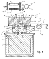
- Fig. 1 shows an overview of a cooling system, which can be used in the context of the present invention.
- the cooling system comprises a rotary valve 1 according to the invention, with a rotary body 6 and a control plate (control disk) 5.
- the rotary body 6 can be rotated by means of an electric motor 2 relative to the control plate 5. In this case, the rotary body 6 rotates about a rotation axis DA.
- the rotary body 6 is held against rotation on a shaft 3 of the electric motor 2, but can in the axial direction (parallel to the axis of rotation DA of the rotary body) on the shaft third slide freely.
- a spring 4 the rotary body 6 is pressed against the control plate 5 even in the absence of working gas pressure.
- a high-pressure side HS and a suction side SS are alternately connected to a cold head 8 or its working gas inlet 9.
- the cold head 8 is designed here as a pulse tube cooler, with a pulse tube 10, a regenerator tube 11, a cold heat exchange region 12 (see heat flow Q), a warm heat exchange region 13 cooled by the outside air, and a buffer volume 14.
- the suction side SS (also called low-pressure side) is connected via a channel 15 with a central bore 15 a of the control plate 5.
- the high-pressure side HS is connected to the vicinity of the rotary body 6, so that the pressure of the working gas on the one hand pushes the rotary body 6 (in addition to the spring 4) against the control plate 5, but also high-pressure working gas penetrate into laterally open recesses 16 of the rotary body 6 and can pass through two acentric channels 17 to the input 9 of the cold head 8 (Note that for simplicity, a pressure housing for the rotary valve 1, in particular the space seals laterally of the rotary body 6, in the Fig. 1 not shown).
- a pressure housing for the rotary valve 1 in particular the space seals laterally of the rotary body 6, in the Fig. 1 not shown.
- the rotary body 6 is supported on the control plate 5 in two areas. First, the working gas sealing surfaces 5a of the control plate 5 and 6a of the rotary body 6 abut each other; they each run perpendicular to the axis of rotation DA. On the other hand, a non-centering bearing 19a is set up. On the control plate 5 and on the rotary body 6 is in each case an annular disk 20, 21 made of an abrasion-resistant material, such as a hardened metal or a ceramic such as SiC attached. The running disks are facing each other with mutually parallel, flat surfaces 20a, 21a. Between these surfaces 20a, 21a, a cage with balls 22 is established.
- the rotary body 6 Since the surfaces 20a, 21a (unlike conventional ball bearings in the prior art) do not form a trough, but run flat and parallel to the radial direction RR, the rotary body 6 has a certain radial play, without the sealing effect on the surfaces 5a, 6a affect; In particular, there is no tilt between the rotary body 6 and the control plate 5, when the rotary body 6 and the control plate 5 are slightly shifted in the radial direction RR against each other. Furthermore, the overlaps of the recesses / channels 15a, 16, 17, 18 are not affected here (see also Fig. 5 ).
- the non-centering bearing thus allows greater tolerances in the relative radial alignment of the rotating body and control plate.
- simpler and less expensive manufacturing and fastening methods for the rotary body are possible.
- the rotary body 6 was made of a plastic (such as polyethene) by injection molding.
- the rotary body 6 After assembly of the rotary valve 1, the rotary body 6 is typically initially attached to the control plate 5 only with the sealing surface 6a (and not via the bearing 19a). By abrasion of the supernatant, however, is rapidly shortened under the action of the spring 4 and possibly the working gas pressure until the bearing 19a holds the rotating body 6, which is particularly rapid when using plastic material on the sealing surface 6a. Then, the rotary body 6 is perfectly fitted, and the bearing 19a prevents further abrasion on the sealing surface 6a.
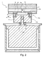
- the Fig. 2 shows the rotary valve of Fig. 1 with non-centering ball bearing 19a, but in a rotated by 90 ° about the axis of rotation DA of the rotary body 6, vertical sectional plane.
- the channel 15 and the recess 18 are now seen to be cut in their respective longitudinal direction.
- the suction side SS (which is connected to channel 15) is not connected to the input of the cold head, as well as in Fig. 1 shown.
- a web 23 seals the outer region of the rotating body 6 (where high pressure of the working gas is always present), where the balls 22 are located, against the recess 18. Note that the balls 22 move along the radial direction RR flat running surfaces 20a, 21a.
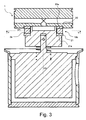
- Fig. 3 is the non-centering bearing 19 b formed with cylindrical rollers 24 which roll on the flat, parallel, opposing surfaces 20 a, 21 a of the pulleys 20, 21,
- the cylinder axes ZA are directed to the axis of rotation DA of the rotating body 6 and perpendicular to Rotary axis DA.
- the running surfaces 20a, 21a are abraded in use, so that even with a less abrasion-resistant material of the discs 20,21 there is no tendency to form a trough.
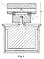
- the Fig. 4 shows the non-centering bearing 19c formed with cylindrical rollers 25 of particularly small diameter; in this case, the bearing 19c is also called “needle bearing".
- the bearing 19c is also called “needle bearing”.
- the Fig. 5 finally shows a cross section through the bearing 19b of Fig. 3 at local line V, but in rotated by 90 ° position of the rotary body. 6 (solid lines) and additionally indicated in the position of Fig. 3 (dotted lines).
- the (circular) cylindrical rollers 24 can be detected, with which the rotary body 6 and the control plate 5 in the bearing 19b roll on each other.
- the channels 17 are connected via the laterally open recesses 16 of the rotary body 6 with the high pressure side of the compressor (see also Fig. 1 ).
- the mouths of the channels 17 are with respect to their radial extent completely within the central recess 18, and also completely within the laterally open recesses 16.
- the central recess 15a is located in its radial extent completely within the central recess 18th in the Fig. 5 is a precisely concentric alignment of rotating body 6 and control plate 5 is shown in which results in respect of all communicating recesses (cutouts, openings, channels) a significant edge spacing AB1, AB2, AB3, AB4 in the radial direction.
- the smallest edge spacing in the concentric alignment, here AB1 in the central recesses 15a and 18, is so large according to the invention that the maximum expected manufacturing and assembly tolerance with respect to a radial mismatch of rotary body 6 and control plate 5 is smaller than the said smallest edge spacing AB1 , Then, the flow or the pressure distribution of the working gas is not affected by the radial mismatch.
Landscapes
- Engineering & Computer Science (AREA)
- General Engineering & Computer Science (AREA)
- Mechanical Engineering (AREA)
- Rolling Contact Bearings (AREA)
- Electrically Driven Valve-Operating Means (AREA)
- Taps Or Cocks (AREA)
- Multiple-Way Valves (AREA)
Description
- Die Erfindung betrifft ein Drehventil für einen Kryokühler, insbesondere für einen Pulsrohrkühler oder für einen Gifford-McMahon-Kühler, umfassend
- einen Drehkörper, welcher um eine Drehachse motorisch rotierbar ist,
- eine Steuerplatte,
- und ein axiales Wälzlager, mit dem der Drehkörper auf der Steuerplatte abrollen kann.
- Ein solches Drehventil ist beispielsweise bekannt geworden durch die
US 2008/0245077 A1 , das die Merkmale des Oberbegriffs des Anspruchs 1 offenbart. - Für den Betrieb vieler technischer Anlagen, beispielsweise supraleitenden Magnetspulen, müssen kryogene Temperaturen bereitgestellt werden. Ein Prinzip zur Erzeugung von Kälte basiert auf der Expansion eines Arbeitsgases. Beim Pulsrohrkühler und beim Gifford-McMahon-Kühler wird abwechselnd ein hoher und niedriger Druck des Arbeitsgases auf einen Kaltkopf geschaltet. In der Praxis wird dazu ein Kompressor abwechselnd mit seiner Saugseite und seiner Hochdruckseite auf den Kaltkopf geschaltet. Dazu wird üblicherweise ein Drehventil eingesetzt.
- Das Drehventil umfasst einen Drehkörper, weicher typischerweise mit einem Elektromotor angetrieben ist, und eine Steuerplatte. Durch die relative Drehung von Drehkörper und Steuerplatte werden abwechselnd verschiedene Strömungskanäle für das Arbeitsgas freigegeben und geschlossen, wodurch der Kaltkopf abwechselnd den gewünschten hohen und niedrigen Druck erfährt.
- Beim Betrieb des Drehventils gleiten eine Oberfläche oder mehrere Oberflächen des Drehkörpers an einer Oberfläche oder mehreren Oberflächen der Steuerplatte ab; in den Kontaktbereichen dichten die Oberflächen das Arbeitsgas ab. Durch das Abgleiten kann es zu Materialabrieb kommen, der schließlich einen Austausch des Drehkörpers und/oder der Steuerplatte erzwingt.
- Aus der
US 2008/0245077 A1 ist es bekannt, den Drehkörper und die Steuerplatte jeweils mit einer umlaufenden Laufrinne zu versehen, wobei zwischen den Laufrinnen ein Kugel-Käfig gehalten ist. Durch dieses Kugellager kann der Verschleiß reduziert werden. - Nachteilig an diesem Stand der Technik ist der hohe Fertigungs- und Montageaufwand für dieses Kugellager. Die Laufrinnen müssen exakt konzentrisch zueinander angeordnet werden; anderenfalls laufen die Kugeln des Kugel-Käfigs aus wenigstens einer der Laufrinnen heraus, und die Oberflächen von Drehkörper und Steuerplatte verkippen gegeneinander. Dies führt zu Undichtigkeiten für das Arbeitsgas und erhöhtem Lagerverschleiß. In der Praxis müssen daher die meisten Bauteile des Drehventils, insbesondere der Drehkörper, aus Metall gefertigt und gefräßt werden, um die durch die Dichtigkeitsanforderungen vorgegebenen Fertigungstoleranzen einhalten zu können.
- Aufgabe der vorliegenden Erfindung ist es, ein Drehventil für einen Kryokühler vorzustellen, welches einen geringen Verschleiß aufweist und dabei einfach zu fertigen und zu montieren ist.
- Diese Aufgabe wird auf überraschend einfache, aber wirkungsvolle Art gelöst durch ein Drehventil der eingangs genannten Art, das dadurch gekennzeichnet ist, dass das axiale Wälzlager als ein in radialer Richtung nicht zentrierendes Lager ausgebildet ist.
- Bei einem erfindungsgemäßen, nicht-zentrierenden Lager können der Drehkörper und die Steuerplatte (Steuerscheibe) in einem gewissen Bereich in radialer Richtung (also in der Ebene senkrecht zur Drehachse des Drehkörpers) - soweit es die Lagerung betrifft - frei aneinander abgleiten. Dann ist es aber unerheblich, ob der Drehkörper und die Steuerplatte im montierten Zustand aufgrund von Toleranzen oder Fehlern bei der Fertigung und/oder Montage geringfügig von einer exakt konzentrischen Ausrichtung bezüglich der Drehachse des Drehkörpers abweichen; die Dichtwirkung an den aneinander abgleitenden Oberflächen bleibt erhalten. Daher kann das Drehventil im Rahmen der Erfindung einfacher gefertigte Bauteile nutzen, etwa einen Drehkörper, der aus Kunststoff in der kostengünstigen Spritzgusstechnik gefertigt ist und vergleichsweise große Fertigungstoleranzen aufweist.
- Zur Einrichtung eines nicht-zentrierenden Lagers sind typischerweise am Drehkörper und an der Steuerplatte ebene, einander gegenüberliegende, zueinander parallele Laufflächen ausgebildet, zwischen denen Rollkörper (wie Kugeln oder bevorzugt Kreiszylinder) angeordnet sind, etwa gehalten in einem Käfig. Aufgrund der ebenen Laufflächen erfolgt in radialer Richtung (senkrecht zur Drehachse des Drehkörpers) keine Zentrierung. Die Laufflächen sind typischerweise kreisringförmig ausgebildet, etwa an am Drehkörper und an der Steuerplatte befestigten Laufscheiben. Man beachte, dass die Laufflächen senkrecht zur Drehachse des Drehkörpers ausgerichtet sind.
- In der Steuerplatte und im Drehkörper sind Ausnehmungen (Ausfräsungen, Öffnungen, Kanäie) vorgesehen. Durch eine während der Drehung des Drehkörpers veränderliche Überlappung der Ausnehmungen wird abwechselnd ein hoher und ein niedriger Druck eines Arbeitsgases (etwa Helium) auf den Kaltkopf (etwa ein Pulsrohr) geschaltet. Bei geeigneter Ausbildung der Ausnehmungen beeinflusst das Spiel in der radialen Ausrichtung von Drehkörper und Steuerplatte das Schaltverhalten des Drehventils nicht (siehe dazu unten).
- Der Drehkörper wird typischerweise mittels eines Elektromotors angetrieben. Ein Wälzlager kann insbesondere ein Kugellager oder einer Zylinder-Rollenlager sein.
- Bei einer bevorzugten Ausführungsform des erfindungsgemäßen Drehventils ist das axiale Wälzlager als ein Zylinder-Rollenlager ausgebildet. Die (Kreis)Zylinder-Rollen sind für die Aufnahme hoher Kräfte geeignet, und die Laufflächen bleiben auch bei längerer Beanspruchung eben, so dass die nicht-zentrierende Eigenschaft des Lagers im Gebrauch auch bei weniger abriebfestem Material der Laufflächen erhalten bleibt. Zylinder-Rollen gestatten außerdem einen vergleichsweise flachen Aufbau. Im Rahmen dieser Ausführungsform sind üblicherweise die Zylinderachsen parallel zu den Laufflächen orientiert und auf die Drehachse des Drehkörpers gerichtet; mit anderen Worten die Zylinderachsen stehen (näherungsweise) senkrecht auf der Drehachse des Drehkörpers.
- Bei einer bevorzugten Weiterbildung dieser Ausführungsform ist das Zylinder-Rollenlager als Nadellager ausgebildet. Das Nadellager weist einen besonders flachen Aufbau auf.
- Besonders vorteilhaft ist eine Ausführungsform, die vorsieht, dass eine Ausnehmung für Arbeitsgas in der Steuerplatte sich in radialer Richtung vollständig innerhalb einer kommunizierenden Ausnehmung für Arbeitsgas im Drehkörper erstreckt oder umgekehrt. Im umgekehrten Fall gilt, dass eine Ausnehmung für Arbeitsgas im Drehkörper sich in radialer Richtung vollständig innerhalb einer kommunizierenden Ausnehmung für Arbeitsgas in der Steuerplatte erstreckt. Bei dieser Orientierung beeinflusst eine geringfügige radiale Fehlzentrierung, etwa aufgrund von Fertigungstoleranzen, das Strömungsverhalten des Arbeitsgases nicht. Die Kantenbeabstandung der Ausnehmungen in radialer Richtung ist typischerweise deutlich größer als das zu erwartende radiale Spiel; das Spiel liegt typischerweise im Bereich bis 0,2 mm oder weniger.
- Bevorzugt ist auch eine Ausführungsform, bei der der Drehkörper mit einer Feder gegen die Steuerplatte gedrückt ist. Die Feder hält ein nichtselbsthaltendes Lager, auch wenn kein Arbeitsgasdruck geschaltet ist. Der Drehkörper sitzt hierbei typischerweise axial beweglich auf einer Welle eines Elektromotors auf.
- Bei einer besonders bevorzugten Ausführungsform ist der Drehkörper aus Kunststoff gefertigt, insbesondere durch Spritzguss. Dadurch können die Herstellungskosten für das erfindungsgemäße Drehventil erheblich reduziert werden.
- Bevorzugt ist schließlich auch noch eine Ausführungsform, bei der die Laufflächen des axialen Wälzlagers an der Steuerplatte und am Drehkörper separat sind von der Dichtfläche oder den Dichtflächen zwischen Steuerplatte und Drehkörper. Ein etwaiger Lagerabrieb beeinflusst dann das Dichtverhalten nicht.
- Weitere Vorteile der Erfindung ergeben sich aus der Beschreibung und der Zeichnung. Ebenso können die vorstehend genannten und die noch weiter ausgeführten Merkmale erfindungsgemäß jeweils einzeln für sich oder zu mehreren in beliebigen Kombinationen Verwendung finden. Die gezeigten und beschriebenen Ausführungsformen sind nicht als abschließende Aufzählung zu verstehen, sondern haben vielmehr beispielhaften Charakter für die Schilderung der Erfindung.
- Die Erfindung ist in der Zeichnung dargestellt und wird anhand von Ausführungsbeispieien näher erläutert. Es zeigen:
- Fig. 1
- einen schematischen Überblick über ein Kühlsystem mit einem Pulsrohrkühler, umfassend ein erfindungsgemäßes Drehventil dargestellt im Axialschnitt;
- Fig. 2
- einen Axialschnitt durch ein erfindungsgemäßes Drehventil einschließlich Motor mit einem Kugellager;
- Fig. 3
- einen Axialschnitt durch ein erfindungsgemäßes Drehventil einschließlich Motor mit einem Zylinderrollenlager;
- Fig. 4
- einen Axialschnitt durch ein erfindungsgemäßes Drehventil einschließlich Motor mit einem Nadellager;
- Fig. 5
- einen Radialschnitt durch das Drehventil von
Fig. 3 auf Höhe der Linie V inFig. 3 . -
Fig. 1 zeigt einen Überblick über ein Kühlsystem, weiches im Rahmen der vorliegenden Erfindung eingesetzt werden kann. - Das Kühlsystem umfasst ein erfindungsgemäßes Drehventil 1, mit einem Drehkörper 6 und einer Steuerplatte (Steuerscheibe) 5. Der Drehkörper 6 kann mittels eines Elektromotors 2 relativ zur Steuerplatte 5 rotiert werden. Dabei dreht sich der Drehkörper 6 um eine Drehachse DA . Der Drehkörper 6 ist verdrehsicher auf einer Welle 3 des Elektromotors 2 gehalten, kann aber in axialer Richtung (parallel zur Drehachse DA des Drehkörpers) auf der Welle 3 frei gleiten. Mit einer Feder 4 wird der Drehkörper 6 auch bei fehlendem Arbeitsgasdruck gegen die Steuerplatte 5 gedrückt.
- Mittels eines Kompressors 7 wird abwechselnd eine Hochdruckseite HS und eine Saugseite SS auf einen Kaltkopf 8 bzw. dessen Arbeitsgaseingang 9 geschaltet. Der Kaltkopf 8 ist hier als ein Pulsrohrkühler ausgebildet, mit einem Pulsrohr 10, einem Regeneratorrohr 11, einem kalten Wärmetauschbereich 12 (vgl. Wärmefluss Q), einem warmen, von der Außenluft gekühlten Wärmetauschbereich 13, und einem Puffervolumen 14.
- Im Drehkörper 6 und in der Steuerplatte 5 sind diverse Ausnehmungen (Ausfräsungen, Öffnungen, Kanäle) vorgesehen, um den Fluss bzw. den Druck des Arbeitsgases (hier Helium) zu kontrollieren. Die Saugseite SS (auch genannt Niederdruckseite) ist über einen Kanal 15 mit einer zentralen Bohrung 15a der Steuerplatte 5 verbunden. Die Hochdruckseite HS ist mit der Umgebung des Drehkörpers 6 verbunden, so dass der Druck des Arbeitsgases zum einen den Drehkörper 6 (zusätzlich zur Feder 4) gegen die Steuerplatte 5 drückt, aber auch Arbeitsgas mit hohem Druck in seitlich offene Ausnehmungen 16 des Drehkörpers 6 eindringen und über zwei azentrische Kanäle 17 zum Eingang 9 des Kaltkopfes 8 gelangen kann (Man beachte, dass zur Vereinfachung ein Druckgehäuse für das Drehventil 1, weiches insbesondere den Raum seitlich des Drehkörpers 6 abdichtet, in der
Fig. 1 nicht dargestellt ist). Durch Drehen des Drehkörpers um 90° um die Achse DA kann auch die Saugseite SS mittels einer zentralen Ausnehmung 18 im Drehkörper auf die Kanäle 17 geschaltet werden (sieheFig. 5 ). - Der Drehkörper 6 stützt sich in zwei Bereichen an der Steuerplatte 5 ab. Zum einen liegen die das Arbeitsgas abdichtenden Oberflächen 5a der Steuerplatte 5 und 6a des Drehkörpers 6 aneinander an; sie verlaufen jeweils senkrecht zur Drehachse DA. Zum anderen ist ein nicht-zentrierendes Lager 19a eingerichtet. An der Steuerplatte 5 und am Drehkörper 6 ist jeweils eine ringförmige Laufscheibe 20, 21 aus einem abriebfesten Material, etwa einem gehärteten Metall oder einer Keramik wie SiC, befestigt. Die Laufscheiben sind mit zueinander parallelen, ebenen Flächen 20a, 21a einander zugewandt. Zwischen diesen Flächen 20a, 21a ist ein Käfig mit Kugeln 22 eingerichtet. Da die Flächen 20a, 21a (anders ais bei herkömmlichen Kugellagern im Stand der Technik) keine Laufrinne ausbilden, sondern eben und parallel zur radialen Richtung RR verlaufen, hat der Drehkörper 6 ein gewisses radiales Spiel, ohne die Dichtwirkung an den Flächen 5a, 6a zu beeinträchtigen; insbesondere kommt es zu keiner Verkippung zwischen Drehkörper 6 und Steuerplatte 5, wenn der Drehkörper 6 und die Steuerplatte 5 geringfügig in radialer Richtung RR gegeneinander verschoben sind. Weiterhin werden hier auch die Überlappungen der Ausnehmungen/Kanäle 15a, 16, 17, 18 nicht beeinträchtigt (siehe dazu auch
Fig. 5 ). - Das nicht-zentrierende Lager erlaubt somit größere Toleranzen bei der relativen radialen Ausrichtung von Drehkörper und Steuerplatte. Insbesondere sind einfachere und kostengünstigere Fertigungs- und Befestigungsverfahren für den Drehkörper möglich. Vorliegend wurde der Drehkörper 6 aus einem Kunststoff (etwa Polyethen) im Spritzgussverfahren hergestellt.
- Nach der Montage des Drehventils 1 liegt typischerweise zunächst der Drehkörper 6 nur mit der Dichtfläche 6a (und nicht über das Lager 19a) an der Steuerplatte 5 an. Durch Abrieb wird der Überstand jedoch unter der Wirkung der Feder 4 und ggf. des Arbeitsgasdrucks schnell verkürzt, bis auch das Lager 19a den Drehkörper 6 hält, was insbesondere bei Verwendung von Kunststoffmaterial an der Dichtfläche 6a rasch erfolgt. Sodann ist der Drehkörper 6 perfekt eingepasst, und das Lager 19a verhindert weiteren Abrieb an der Dichtfläche 6a.
- In den
Figuren 2 ,3 und4 sind jeweils verschiedene mögiiche Ausbildungen des Lagers des Drehventils 1 näher erläutert. Es werden im Folgenden nur die Unterschiede zurFig. 1 erläutert. - Die
Fig. 2 zeigt das Drehventil vonFig. 1 mit nicht-zentrierendem Kugellager 19a, jedoch in einer um 90° um die Drehachse DA des Drehkörpers 6 rotierter, vertikaler Schnittebene. Der Kanal 15 und die Ausnehmung 18 sind nunmehr in ihrer jeweiligen Längsrichtung geschnitten zu sehen. Die Saugseite SS (die mit Kanal 15 verbunden ist) ist nicht auf den Eingang des Kaltkopfs geschaltet, wie auch inFig. 1 dargestellt. Ein Steg 23 dichtet den Außenbereich des Drehkörpers 6 (wo stets Hochdruck des Arbeitsgases anliegt), wo sich auch die Kugeln 22 befinden, gegen die Ausnehmung 18 ab. Man beachte, dass sich die Kugeln 22 auf entlang der radialen Richtung RR ebenen Laufflächen 20a, 21a bewegen. - In der
Fig. 3 ist das nicht-zentrierende Lager 19b mit Zylinderrollen 24 ausgebildet, die auf den ebenen, parallelen, sich gegenüber liegenden Flächen 20a, 21 a der Laufscheiben 20, 21 abrollen, Die Zylinderachsen ZA sind auf die Drehachse DA des Drehkörpers 6 gerichtet und verlaufen senkrecht zur Drehachse DA. Die Laufflächen 20a, 21 a werden bei Benutzung eben abgerieben, so dass auch bei einem weniger abriebfesten Material der Laufscheiben 20,21 keine Neigung zur Ausbildung einer Laufrinne besteht. - Die
Fig. 4 zeigt das nicht-zentrierende Lager 19c ausgebildet mit Zylinderrollen 25 besonders geringen Durchmessers; in diesem Falle wird das Lager 19c auch "Nadellager" genannt. Durch Verwendung eines Nadellagers 19c kann die Bauhöhe BH des Drehventils 1 in axialer Richtung reduziert werden. - Die
Fig. 5 zeigt schließlich einen Querschnitt durch das Lager 19b vonFig. 3 bei dortiger Linie V, jedoch in um 90° verdrehter Stellung des Drehkörpers 6 (durchgezogenen Linien) und zusätzlich angedeutet in der Stellung vonFig. 3 (gepunktete Linien). - Im Querschnitt können die (Kreis-)Zylinderrollen 24 erkannt werden, mit denen der Drehkörper 6 und die Steuerplatte 5 im Lager 19b aufeinander abrollen.
- In der mit den durchgezogenen Linien gezeigten Stellung verbindet gerade die zentrale Ausnehmung 18 des Drehkörpers 6 die an der Unterseite der Steuerplatte 5 mündenden Kanäle 17 mit der zentralen Bohrung 15a, welche mit der Saugseite des Kompressors verbunden ist.
- In der durch die gepunkteten Linien angedeuteten relativen Orientierung von Drehkörper 6 und Steuerplatte 5 werden die Kanäle 17 über die seitlich offenen Ausnehmungen 16 des Drehkörpers 6 mit der Hochdruckseite des Kompressors verbunden (siehe auch
Fig. 1 ). - Die Mündungen der Kanäle 17 liegen bezüglich ihrer radialen Ausdehnung vollständig innerhalb der zentralen Ausnehmung 18, und auch vollständig innerhalb der seitlich offenen Ausnehmungen 16. Ebenso liegt die zentrale Ausnehmung 15a in ihrer radialen Ausdehnung vollständig innerhalb der zentralen Ausnehmung 18. in der
Fig. 5 ist eine exakt konzentrische Ausrichtung von Drehkörper 6 und Steuerplatte 5 gezeigt, bei der sich bezüglich aller kommunizierender Ausnehmungen (Ausfräsungen, Öffnungen, Kanäle) eine erhebliche Kantenbeabstandung AB1, AB2, AB3, AB4 in radialer Richtung ergibt. Die kleinste Kantenbeabstandung in der konzentrischen Ausrichtung, hier AB1 bei den zentralen Ausnehmungen 15a und 18, ist erfindungsgemäß so groß, dass die maximal zu erwartende Fertigungs- und Montagetoleranz bezüglich einer radialen Fehlpassung von Drehkörper 6 und Steuerplatte 5 kleiner als die besagte kleinste Kantenbeabstandung AB1 ist. Dann wird durch die radiale Fehlpassung der Fluss bzw. die Druckverteilung des Arbeitsgases nicht beeinträchtigt.
Claims (7)
- Drehventil (1) für einen Kryokühler, insbesondere für einen Pulsrohrkühler oder für einen Gifford-McMahon-Kühler, umfassend- einen Drehkörper (6), welcher um eine Drehachse (DA) motorisch rotierbar ist,- eine Steuerplatte (5),- und ein axiales Wälzlager, mit dem der Drehkörper (6) auf der Steuerplatte (5) abrollen kann,dadurch gekennzeichnet,
dass das axiale Wälzlager als ein in radialer Richtung (RR) nicht zentrierendes Lager (19a-19c) ausgebildet ist. - Drehventil (1) nach Anspruch 1, dadurch gekennzeichnet, dass das axiale Wälzlager als ein Zylinder-Rollenlager (19b, 19c) ausgebildet ist.
- Drehventil (1) nach Anspruch 2, dadurch gekennzeichnet, dass das Zylinder-Rollenlager (19b, 19c) als Nadellager (19c) ausgebildet ist.
- Drehventil (1) nach einem der vorhergehenden Ansprüche, dadurch gekennzeichnet, dass eine Ausnehmung (15a, 17) für Arbeitsgas in der Steuerplatte (5) sich in radialer Richtung (RR) vollständig innerhalb einer kommunizierenden Ausnehmung (16,18) für Arbeitsgas im Drehkörper (6) erstreckt oder umgekehrt.
- Drehventil (1) nach einem der vorhergehenden Ansprüche, dadurch gekennzeichnet, dass der Drehkörper (6) mit einer Feder (4) gegen die Steuerplatte (5) gedrückt ist.
- Drehventil (1) nach einem der vorhergehenden Ansprüche, dadurch gekennzeichnet, dass der Drehkörper (6) aus Kunststoff gefertigt ist. insbesondere durch Spritzguss.
- Drehventil (1) nach einem der vorhergehenden Ansprüche, dadurch gekennzeichnet, dass die Laufflächen (20a, 21a) des axialen Wälzlagers an der Steuerplatte (5) und am Drehkörper (6) separat sind von der Dichtfiäche oder den Dichtflächen (5a, 6a) zwischen Steuerplatte (5) und Drehkörper (6).
Applications Claiming Priority (2)
| Application Number | Priority Date | Filing Date | Title |
|---|---|---|---|
| DE102010001498A DE102010001498A1 (de) | 2010-02-02 | 2010-02-02 | Drehventil für einen Kryokühler, insbesondere für einen Pulsrohrkühler oder für einen Gifford-McMahon-Kühler |
| PCT/EP2011/051313 WO2011095455A1 (de) | 2010-02-02 | 2011-01-31 | Motorisches drehventil |
Publications (2)
| Publication Number | Publication Date |
|---|---|
| EP2531753A1 EP2531753A1 (de) | 2012-12-12 |
| EP2531753B1 true EP2531753B1 (de) | 2014-12-17 |
Family
ID=44063316
Family Applications (1)
| Application Number | Title | Priority Date | Filing Date |
|---|---|---|---|
| EP11702959.5A Not-in-force EP2531753B1 (de) | 2010-02-02 | 2011-01-31 | Motorisches drehventil |
Country Status (7)
| Country | Link |
|---|---|
| US (1) | US20120292548A1 (de) |
| EP (1) | EP2531753B1 (de) |
| JP (1) | JP5735542B2 (de) |
| KR (1) | KR20120125329A (de) |
| CN (1) | CN102741598B (de) |
| DE (1) | DE102010001498A1 (de) |
| WO (1) | WO2011095455A1 (de) |
Families Citing this family (6)
| Publication number | Priority date | Publication date | Assignee | Title |
|---|---|---|---|---|
| GB2496573B (en) * | 2011-09-27 | 2016-08-31 | Oxford Instr Nanotechnology Tools Ltd | Apparatus and method for controlling a cryogenic cooling system |
| DE102014214819B3 (de) | 2014-07-29 | 2015-08-20 | Bruker Biospin Gmbh | Pulsrohrkühler-System mit kraftkompensierter Drehventilleitung |
| CN105545860A (zh) * | 2016-01-20 | 2016-05-04 | 浙江大学 | 一种液控换向旋转阀 |
| JP6781651B2 (ja) * | 2017-03-13 | 2020-11-04 | 住友重機械工業株式会社 | 極低温冷凍機、極低温冷凍機用のロータリーバルブユニット及びロータリーバルブ |
| CN109578621B (zh) * | 2018-12-20 | 2023-07-28 | 江苏新苏承环保设备有限公司 | 一种rto气动旋转阀门 |
| CN117145996A (zh) * | 2023-08-30 | 2023-12-01 | 深圳国际量子研究院 | 旋转阀及制冷设备 |
Family Cites Families (18)
| Publication number | Priority date | Publication date | Assignee | Title |
|---|---|---|---|---|
| US2317407A (en) * | 1941-07-21 | 1943-04-27 | Samiran David | Fuel cock |
| US2696219A (en) * | 1951-03-27 | 1954-12-07 | Lilburn S Barksdale | Fluid valve |
| US2736339A (en) * | 1952-11-28 | 1956-02-28 | Parker Appliance Co | Rotary valve |
| US2988108A (en) * | 1958-07-31 | 1961-06-13 | Robertshaw Fulton Controls Co | Multi-way valve |
| GB907226A (en) * | 1958-11-27 | 1962-10-03 | Wilmot Breeden Ltd | Fluid control valves |
| GB1240480A (en) * | 1967-08-17 | 1971-07-28 | Daikin Ind Ltd | Directional control valve |
| US3587647A (en) * | 1969-09-23 | 1971-06-28 | John D Walters | Four way valve |
| US4522033A (en) * | 1984-07-02 | 1985-06-11 | Cvi Incorporated | Cryogenic refrigerator with gas spring loaded valve |
| US4893653A (en) * | 1989-01-04 | 1990-01-16 | Ferrigno Joseph T | Electrically controlled faucet |
| US5429482A (en) * | 1991-09-11 | 1995-07-04 | Kabushiki Kaisha Toyoda Jidoshokki Seisakusho | Reciprocatory piston type compressor |
| JP2001074043A (ja) * | 1999-09-03 | 2001-03-23 | Koyo Seiko Co Ltd | 偏心スラスト軸受 |
| JP2002228288A (ja) * | 2001-01-29 | 2002-08-14 | Aisin Seiki Co Ltd | パルス管冷凍機 |
| US7022229B1 (en) * | 2003-12-19 | 2006-04-04 | Uop Llc | Adsorption separation system |
| JP4137805B2 (ja) * | 2004-01-30 | 2008-08-20 | あさひ化工機株式会社 | ロータリー弁を用いた酸素濃縮装置 |
| WO2005088210A1 (en) * | 2004-03-08 | 2005-09-22 | Sumitomo Heavy Industries, Ltd. | Wearless valve for cryorefrigerator |
| US20080245077A1 (en) | 2005-06-10 | 2008-10-09 | Sumitomo Heavy Industries, Ltd. | Multiple Rotary Valve For Pulse Tube Refrigerator |
| JP2008051146A (ja) * | 2006-08-22 | 2008-03-06 | Kirin Techno-System Co Ltd | ロータリ弁 |
| CN201177059Y (zh) * | 2008-01-25 | 2009-01-07 | 沈阳欧科流体控制技术有限公司 | 带有防抱轴超低扭装置的高温高压旋转阀 |
-
2010
- 2010-02-02 DE DE102010001498A patent/DE102010001498A1/de not_active Withdrawn
-
2011
- 2011-01-31 KR KR1020127022782A patent/KR20120125329A/ko not_active Withdrawn
- 2011-01-31 EP EP11702959.5A patent/EP2531753B1/de not_active Not-in-force
- 2011-01-31 US US13/575,306 patent/US20120292548A1/en not_active Abandoned
- 2011-01-31 WO PCT/EP2011/051313 patent/WO2011095455A1/de not_active Ceased
- 2011-01-31 JP JP2012550472A patent/JP5735542B2/ja not_active Expired - Fee Related
- 2011-01-31 CN CN201180008042.4A patent/CN102741598B/zh not_active Expired - Fee Related
Also Published As
| Publication number | Publication date |
|---|---|
| JP5735542B2 (ja) | 2015-06-17 |
| EP2531753A1 (de) | 2012-12-12 |
| KR20120125329A (ko) | 2012-11-14 |
| WO2011095455A1 (de) | 2011-08-11 |
| DE102010001498A1 (de) | 2011-08-04 |
| CN102741598A (zh) | 2012-10-17 |
| JP2013519059A (ja) | 2013-05-23 |
| US20120292548A1 (en) | 2012-11-22 |
| CN102741598B (zh) | 2015-08-26 |
Similar Documents
| Publication | Publication Date | Title |
|---|---|---|
| EP2531753B1 (de) | Motorisches drehventil | |
| DE102011118622B4 (de) | Axialkolbenmaschine mit Auslasssteuerung | |
| DE102011000104A1 (de) | Hochdruck-Schaltventil für die Hochleistungsflüssigkeitschromatographie | |
| EP1731722A1 (de) | Nockenwellenversteller mit Schwenkmotorrotor mit verringerter Leckage | |
| DE102010036917A1 (de) | Axialkolbenmaschine | |
| WO2012034619A1 (de) | Axialkolbenmaschine | |
| DE102011052481A1 (de) | Axialkolbenmaschine | |
| DE102016118133A1 (de) | Drehschieberventil | |
| DE102007016209B4 (de) | Ventiltrieb für Gaswechselventile mit Axialkraftreduktion in Nockenwelle | |
| EP1723335A1 (de) | Axialkolbenmaschine | |
| EP0644981B1 (de) | Kolbenmaschine | |
| DE4326323A1 (de) | Taumelscheibenverdichter | |
| DE10060947A1 (de) | Radialkolbenhydraulikmotor | |
| EP1749146A1 (de) | Nockenwellenversteller | |
| DE102009041125B4 (de) | Gasdynamische Druckwellenmaschine | |
| EP1254332B1 (de) | Ventil, insbesondere druckreduzierventil | |
| DE3245688C2 (de) | ||
| EP3489460B1 (de) | Ventil für eine dampfturbine | |
| DE3433762C2 (de) | Flügelzellenmaschine | |
| DE19921951A1 (de) | Piezobetätigte Kolbenpumpe | |
| CH428775A (de) | Dampf- oder Gasturbine | |
| DE102011119906B4 (de) | Rotationskolbenmotor und Abdichtungsverfahren für einen Rotationskolbenmotor | |
| EP2119947A2 (de) | Doppelabsperrventil, insbesondere für gasförmige Medien | |
| DE102007027087B3 (de) | Einspritzpumpenanordnung an einem Zwei- oder Vierzylinder-Dieselmotor | |
| DE102023124122A1 (de) | Hydraulische, hubverstellbare Kolbenmaschine |
Legal Events
| Date | Code | Title | Description |
|---|---|---|---|
| PUAI | Public reference made under article 153(3) epc to a published international application that has entered the european phase |
Free format text: ORIGINAL CODE: 0009012 |
|
| 17P | Request for examination filed |
Effective date: 20120903 |
|
| AK | Designated contracting states |
Kind code of ref document: A1 Designated state(s): AL AT BE BG CH CY CZ DE DK EE ES FI FR GB GR HR HU IE IS IT LI LT LU LV MC MK MT NL NO PL PT RO RS SE SI SK SM TR |
|
| DAX | Request for extension of the european patent (deleted) | ||
| GRAP | Despatch of communication of intention to grant a patent |
Free format text: ORIGINAL CODE: EPIDOSNIGR1 |
|
| INTG | Intention to grant announced |
Effective date: 20140808 |
|
| GRAS | Grant fee paid |
Free format text: ORIGINAL CODE: EPIDOSNIGR3 |
|
| GRAA | (expected) grant |
Free format text: ORIGINAL CODE: 0009210 |
|
| AK | Designated contracting states |
Kind code of ref document: B1 Designated state(s): AL AT BE BG CH CY CZ DE DK EE ES FI FR GB GR HR HU IE IS IT LI LT LU LV MC MK MT NL NO PL PT RO RS SE SI SK SM TR |
|
| REG | Reference to a national code |
Ref country code: GB Ref legal event code: FG4D Free format text: NOT ENGLISH |
|
| REG | Reference to a national code |
Ref country code: CH Ref legal event code: EP |
|
| REG | Reference to a national code |
Ref country code: IE Ref legal event code: FG4D Free format text: LANGUAGE OF EP DOCUMENT: GERMAN |
|
| REG | Reference to a national code |
Ref country code: AT Ref legal event code: REF Ref document number: 702181 Country of ref document: AT Kind code of ref document: T Effective date: 20150115 |
|
| REG | Reference to a national code |
Ref country code: NL Ref legal event code: T3 |
|
| REG | Reference to a national code |
Ref country code: DE Ref legal event code: R096 Ref document number: 502011005298 Country of ref document: DE Effective date: 20150219 |
|
| PG25 | Lapsed in a contracting state [announced via postgrant information from national office to epo] |
Ref country code: LT Free format text: LAPSE BECAUSE OF FAILURE TO SUBMIT A TRANSLATION OF THE DESCRIPTION OR TO PAY THE FEE WITHIN THE PRESCRIBED TIME-LIMIT Effective date: 20141217 Ref country code: NO Free format text: LAPSE BECAUSE OF FAILURE TO SUBMIT A TRANSLATION OF THE DESCRIPTION OR TO PAY THE FEE WITHIN THE PRESCRIBED TIME-LIMIT Effective date: 20150317 Ref country code: FI Free format text: LAPSE BECAUSE OF FAILURE TO SUBMIT A TRANSLATION OF THE DESCRIPTION OR TO PAY THE FEE WITHIN THE PRESCRIBED TIME-LIMIT Effective date: 20141217 |
|
| REG | Reference to a national code |
Ref country code: LT Ref legal event code: MG4D |
|
| PG25 | Lapsed in a contracting state [announced via postgrant information from national office to epo] |
Ref country code: HR Free format text: LAPSE BECAUSE OF FAILURE TO SUBMIT A TRANSLATION OF THE DESCRIPTION OR TO PAY THE FEE WITHIN THE PRESCRIBED TIME-LIMIT Effective date: 20141217 Ref country code: LV Free format text: LAPSE BECAUSE OF FAILURE TO SUBMIT A TRANSLATION OF THE DESCRIPTION OR TO PAY THE FEE WITHIN THE PRESCRIBED TIME-LIMIT Effective date: 20141217 Ref country code: SE Free format text: LAPSE BECAUSE OF FAILURE TO SUBMIT A TRANSLATION OF THE DESCRIPTION OR TO PAY THE FEE WITHIN THE PRESCRIBED TIME-LIMIT Effective date: 20141217 Ref country code: RS Free format text: LAPSE BECAUSE OF FAILURE TO SUBMIT A TRANSLATION OF THE DESCRIPTION OR TO PAY THE FEE WITHIN THE PRESCRIBED TIME-LIMIT Effective date: 20141217 Ref country code: GR Free format text: LAPSE BECAUSE OF FAILURE TO SUBMIT A TRANSLATION OF THE DESCRIPTION OR TO PAY THE FEE WITHIN THE PRESCRIBED TIME-LIMIT Effective date: 20150318 |
|
| PG25 | Lapsed in a contracting state [announced via postgrant information from national office to epo] |
Ref country code: ES Free format text: LAPSE BECAUSE OF FAILURE TO SUBMIT A TRANSLATION OF THE DESCRIPTION OR TO PAY THE FEE WITHIN THE PRESCRIBED TIME-LIMIT Effective date: 20141217 Ref country code: CZ Free format text: LAPSE BECAUSE OF FAILURE TO SUBMIT A TRANSLATION OF THE DESCRIPTION OR TO PAY THE FEE WITHIN THE PRESCRIBED TIME-LIMIT Effective date: 20141217 Ref country code: EE Free format text: LAPSE BECAUSE OF FAILURE TO SUBMIT A TRANSLATION OF THE DESCRIPTION OR TO PAY THE FEE WITHIN THE PRESCRIBED TIME-LIMIT Effective date: 20141217 Ref country code: SK Free format text: LAPSE BECAUSE OF FAILURE TO SUBMIT A TRANSLATION OF THE DESCRIPTION OR TO PAY THE FEE WITHIN THE PRESCRIBED TIME-LIMIT Effective date: 20141217 Ref country code: RO Free format text: LAPSE BECAUSE OF FAILURE TO SUBMIT A TRANSLATION OF THE DESCRIPTION OR TO PAY THE FEE WITHIN THE PRESCRIBED TIME-LIMIT Effective date: 20141217 |
|
| PG25 | Lapsed in a contracting state [announced via postgrant information from national office to epo] |
Ref country code: IS Free format text: LAPSE BECAUSE OF FAILURE TO SUBMIT A TRANSLATION OF THE DESCRIPTION OR TO PAY THE FEE WITHIN THE PRESCRIBED TIME-LIMIT Effective date: 20150417 Ref country code: LU Free format text: LAPSE BECAUSE OF FAILURE TO SUBMIT A TRANSLATION OF THE DESCRIPTION OR TO PAY THE FEE WITHIN THE PRESCRIBED TIME-LIMIT Effective date: 20150131 Ref country code: PL Free format text: LAPSE BECAUSE OF FAILURE TO SUBMIT A TRANSLATION OF THE DESCRIPTION OR TO PAY THE FEE WITHIN THE PRESCRIBED TIME-LIMIT Effective date: 20141217 |
|
| REG | Reference to a national code |
Ref country code: DE Ref legal event code: R097 Ref document number: 502011005298 Country of ref document: DE |
|
| PG25 | Lapsed in a contracting state [announced via postgrant information from national office to epo] |
Ref country code: MC Free format text: LAPSE BECAUSE OF FAILURE TO SUBMIT A TRANSLATION OF THE DESCRIPTION OR TO PAY THE FEE WITHIN THE PRESCRIBED TIME-LIMIT Effective date: 20141217 |
|
| PLBE | No opposition filed within time limit |
Free format text: ORIGINAL CODE: 0009261 |
|
| STAA | Information on the status of an ep patent application or granted ep patent |
Free format text: STATUS: NO OPPOSITION FILED WITHIN TIME LIMIT |
|
| PG25 | Lapsed in a contracting state [announced via postgrant information from national office to epo] |
Ref country code: DK Free format text: LAPSE BECAUSE OF FAILURE TO SUBMIT A TRANSLATION OF THE DESCRIPTION OR TO PAY THE FEE WITHIN THE PRESCRIBED TIME-LIMIT Effective date: 20141217 |
|
| REG | Reference to a national code |
Ref country code: IE Ref legal event code: MM4A |
|
| 26N | No opposition filed |
Effective date: 20150918 |
|
| PG25 | Lapsed in a contracting state [announced via postgrant information from national office to epo] |
Ref country code: IT Free format text: LAPSE BECAUSE OF FAILURE TO SUBMIT A TRANSLATION OF THE DESCRIPTION OR TO PAY THE FEE WITHIN THE PRESCRIBED TIME-LIMIT Effective date: 20141217 |
|
| REG | Reference to a national code |
Ref country code: FR Ref legal event code: PLFP Year of fee payment: 6 |
|
| PG25 | Lapsed in a contracting state [announced via postgrant information from national office to epo] |
Ref country code: IE Free format text: LAPSE BECAUSE OF NON-PAYMENT OF DUE FEES Effective date: 20150131 |
|
| PG25 | Lapsed in a contracting state [announced via postgrant information from national office to epo] |
Ref country code: SI Free format text: LAPSE BECAUSE OF FAILURE TO SUBMIT A TRANSLATION OF THE DESCRIPTION OR TO PAY THE FEE WITHIN THE PRESCRIBED TIME-LIMIT Effective date: 20141217 |
|
| PG25 | Lapsed in a contracting state [announced via postgrant information from national office to epo] |
Ref country code: MT Free format text: LAPSE BECAUSE OF FAILURE TO SUBMIT A TRANSLATION OF THE DESCRIPTION OR TO PAY THE FEE WITHIN THE PRESCRIBED TIME-LIMIT Effective date: 20141217 |
|
| REG | Reference to a national code |
Ref country code: FR Ref legal event code: PLFP Year of fee payment: 7 |
|
| REG | Reference to a national code |
Ref country code: AT Ref legal event code: MM01 Ref document number: 702181 Country of ref document: AT Kind code of ref document: T Effective date: 20160131 |
|
| PG25 | Lapsed in a contracting state [announced via postgrant information from national office to epo] |
Ref country code: AT Free format text: LAPSE BECAUSE OF NON-PAYMENT OF DUE FEES Effective date: 20160131 Ref country code: BG Free format text: LAPSE BECAUSE OF FAILURE TO SUBMIT A TRANSLATION OF THE DESCRIPTION OR TO PAY THE FEE WITHIN THE PRESCRIBED TIME-LIMIT Effective date: 20141217 Ref country code: HU Free format text: LAPSE BECAUSE OF FAILURE TO SUBMIT A TRANSLATION OF THE DESCRIPTION OR TO PAY THE FEE WITHIN THE PRESCRIBED TIME-LIMIT; INVALID AB INITIO Effective date: 20110131 Ref country code: SM Free format text: LAPSE BECAUSE OF FAILURE TO SUBMIT A TRANSLATION OF THE DESCRIPTION OR TO PAY THE FEE WITHIN THE PRESCRIBED TIME-LIMIT Effective date: 20141217 |
|
| PG25 | Lapsed in a contracting state [announced via postgrant information from national office to epo] |
Ref country code: CY Free format text: LAPSE BECAUSE OF FAILURE TO SUBMIT A TRANSLATION OF THE DESCRIPTION OR TO PAY THE FEE WITHIN THE PRESCRIBED TIME-LIMIT Effective date: 20141217 |
|
| PG25 | Lapsed in a contracting state [announced via postgrant information from national office to epo] |
Ref country code: BE Free format text: LAPSE BECAUSE OF NON-PAYMENT OF DUE FEES Effective date: 20150131 Ref country code: PT Free format text: LAPSE BECAUSE OF FAILURE TO SUBMIT A TRANSLATION OF THE DESCRIPTION OR TO PAY THE FEE WITHIN THE PRESCRIBED TIME-LIMIT Effective date: 20150417 |
|
| PG25 | Lapsed in a contracting state [announced via postgrant information from national office to epo] |
Ref country code: TR Free format text: LAPSE BECAUSE OF FAILURE TO SUBMIT A TRANSLATION OF THE DESCRIPTION OR TO PAY THE FEE WITHIN THE PRESCRIBED TIME-LIMIT Effective date: 20141217 |
|
| REG | Reference to a national code |
Ref country code: FR Ref legal event code: PLFP Year of fee payment: 8 |
|
| PG25 | Lapsed in a contracting state [announced via postgrant information from national office to epo] |
Ref country code: MK Free format text: LAPSE BECAUSE OF FAILURE TO SUBMIT A TRANSLATION OF THE DESCRIPTION OR TO PAY THE FEE WITHIN THE PRESCRIBED TIME-LIMIT Effective date: 20141217 |
|
| PG25 | Lapsed in a contracting state [announced via postgrant information from national office to epo] |
Ref country code: AL Free format text: LAPSE BECAUSE OF FAILURE TO SUBMIT A TRANSLATION OF THE DESCRIPTION OR TO PAY THE FEE WITHIN THE PRESCRIBED TIME-LIMIT Effective date: 20141217 |
|
| PGFP | Annual fee paid to national office [announced via postgrant information from national office to epo] |
Ref country code: GB Payment date: 20200127 Year of fee payment: 10 Ref country code: NL Payment date: 20200122 Year of fee payment: 10 Ref country code: DE Payment date: 20200123 Year of fee payment: 10 |
|
| PGFP | Annual fee paid to national office [announced via postgrant information from national office to epo] |
Ref country code: CH Payment date: 20200127 Year of fee payment: 10 |
|
| PGFP | Annual fee paid to national office [announced via postgrant information from national office to epo] |
Ref country code: FR Payment date: 20200123 Year of fee payment: 10 |
|
| REG | Reference to a national code |
Ref country code: DE Ref legal event code: R119 Ref document number: 502011005298 Country of ref document: DE |
|
| REG | Reference to a national code |
Ref country code: CH Ref legal event code: PL |
|
| REG | Reference to a national code |
Ref country code: NL Ref legal event code: MM Effective date: 20210201 |
|
| GBPC | Gb: european patent ceased through non-payment of renewal fee |
Effective date: 20210131 |
|
| PG25 | Lapsed in a contracting state [announced via postgrant information from national office to epo] |
Ref country code: FR Free format text: LAPSE BECAUSE OF NON-PAYMENT OF DUE FEES Effective date: 20210131 Ref country code: NL Free format text: LAPSE BECAUSE OF NON-PAYMENT OF DUE FEES Effective date: 20210201 |
|
| PG25 | Lapsed in a contracting state [announced via postgrant information from national office to epo] |
Ref country code: GB Free format text: LAPSE BECAUSE OF NON-PAYMENT OF DUE FEES Effective date: 20210131 Ref country code: CH Free format text: LAPSE BECAUSE OF NON-PAYMENT OF DUE FEES Effective date: 20210131 Ref country code: DE Free format text: LAPSE BECAUSE OF NON-PAYMENT OF DUE FEES Effective date: 20210803 Ref country code: LI Free format text: LAPSE BECAUSE OF NON-PAYMENT OF DUE FEES Effective date: 20210131 |