EP2529412B1 - Solarmodulanordnungen und diodenkabel - Google Patents
Solarmodulanordnungen und diodenkabel Download PDFInfo
- Publication number
- EP2529412B1 EP2529412B1 EP11702417.4A EP11702417A EP2529412B1 EP 2529412 B1 EP2529412 B1 EP 2529412B1 EP 11702417 A EP11702417 A EP 11702417A EP 2529412 B1 EP2529412 B1 EP 2529412B1
- Authority
- EP
- European Patent Office
- Prior art keywords
- solar module
- diode
- cable
- connection
- solar
- Prior art date
- Legal status (The legal status is an assumption and is not a legal conclusion. Google has not performed a legal analysis and makes no representation as to the accuracy of the status listed.)
- Active
Links
Images
Classifications
-
- H—ELECTRICITY
- H01—ELECTRIC ELEMENTS
- H01R—ELECTRICALLY-CONDUCTIVE CONNECTIONS; STRUCTURAL ASSOCIATIONS OF A PLURALITY OF MUTUALLY-INSULATED ELECTRICAL CONNECTING ELEMENTS; COUPLING DEVICES; CURRENT COLLECTORS
- H01R13/00—Details of coupling devices of the kinds covered by groups H01R12/70 or H01R24/00 - H01R33/00
- H01R13/66—Structural association with built-in electrical component
-
- H—ELECTRICITY
- H10—SEMICONDUCTOR DEVICES; ELECTRIC SOLID-STATE DEVICES NOT OTHERWISE PROVIDED FOR
- H10F—INORGANIC SEMICONDUCTOR DEVICES SENSITIVE TO INFRARED RADIATION, LIGHT, ELECTROMAGNETIC RADIATION OF SHORTER WAVELENGTH OR CORPUSCULAR RADIATION
- H10F19/00—Integrated devices, or assemblies of multiple devices, comprising at least one photovoltaic cell covered by group H10F10/00, e.g. photovoltaic modules
- H10F19/90—Structures for connecting between photovoltaic cells, e.g. interconnections or insulating spacers
-
- H—ELECTRICITY
- H02—GENERATION; CONVERSION OR DISTRIBUTION OF ELECTRIC POWER
- H02S—GENERATION OF ELECTRIC POWER BY CONVERSION OF INFRARED RADIATION, VISIBLE LIGHT OR ULTRAVIOLET LIGHT, e.g. USING PHOTOVOLTAIC [PV] MODULES
- H02S40/00—Components or accessories in combination with PV modules, not provided for in groups H02S10/00 - H02S30/00
- H02S40/30—Electrical components
- H02S40/34—Electrical components comprising specially adapted electrical connection means to be structurally associated with the PV module, e.g. junction boxes
-
- Y—GENERAL TAGGING OF NEW TECHNOLOGICAL DEVELOPMENTS; GENERAL TAGGING OF CROSS-SECTIONAL TECHNOLOGIES SPANNING OVER SEVERAL SECTIONS OF THE IPC; TECHNICAL SUBJECTS COVERED BY FORMER USPC CROSS-REFERENCE ART COLLECTIONS [XRACs] AND DIGESTS
- Y02—TECHNOLOGIES OR APPLICATIONS FOR MITIGATION OR ADAPTATION AGAINST CLIMATE CHANGE
- Y02E—REDUCTION OF GREENHOUSE GAS [GHG] EMISSIONS, RELATED TO ENERGY GENERATION, TRANSMISSION OR DISTRIBUTION
- Y02E10/00—Energy generation through renewable energy sources
- Y02E10/50—Photovoltaic [PV] energy
Definitions
- the invention relates to a genus of a solar module assembly according to the preamble of the independent claim.
- Solar modules for photovoltaic conversion of sunlight into electrical power are increasingly used for energy production.
- thin-film solar modules based on polycrystalline chalcopyrite semiconductors have proved to be advantageous, with copper indium diselenide (CuInSe 2 or CIS) in particular being distinguished by a particularly high absorption coefficient due to its bandgap adapted to the spectrum of sunlight. Since only voltage levels of less than 1 volt can be achieved with individual solar cells, several solar cells are usually connected in series in a solar module in order to obtain a technically useful output voltage in this way.
- Thin-film solar modules offer the particular advantage that the solar cells can already be connected in series during layer production in integrated form.
- Thin-film solar modules have already been described several times in the patent literature. By way of example only, reference is made to the patent DE 4324318 C1 directed.
- junction boxes For connection to an electrical load solar modules have at least one junction box, which is typically mounted on the back of the solar module.
- the junction box contains connection contacts.
- the electrical connection between the terminal contacts and the solar cell circuit is performed, for example in the form of metal bands from the solar cell circuit out of the module in the junction box.
- several solar modules are connected by connected to the junction boxes connecting cable to a module string in series. It is known to provide a freewheeling or bypass diode for each module, which is connected to the connection contacts of the solar module is connected in the reverse direction in the normal operating state in which the module supplies power.
- the Japanese publication JP 7 131045 A shows a connecting cable for connecting a solar module with a single junction box to a multiple solar modules common power line.
- a freewheeling diode is included in a module-side plug of the connection cable.
- the object of the present invention is to develop conventional solar modules in an advantageous manner, in particular, the production should be simplified and manufacturing costs to be reduced.
- a solar module arrangement which comprises a solar module for photovoltaic power generation.
- the solar module is provided with a plurality of series-connected solar cells.
- the solar module can be a crystalline, multicrystalline silicon solar module or a thin-film solar module with integrated, series-connected solar cells.
- the semiconductor layer may consist of a chalcopyrite compound, which may be, for example, an I-III-VI semiconductor from the group of copper-indium / gallium disulphide / diselenide (Cu (InGa) (SSE) 2 ), for example copper -Indium diselenide (CuInSe 2 or CIS) or related compounds, which may be cadmium telluride and / or thin-film silicon.
- the solar module arrangement further comprises a first connection housing connected to the solar module and a second connection housing connected to the solar module for connecting the solar module to an electrical load.
- a freewheeling or bypass diode connected in antiparallel with respect to the solar module is furthermore provided, by means of which protection of the solar module is achieved in the absence of power generation, for example due to shading.
- the two terminal contacts of the solar module are electrically connected to each other for this purpose via the freewheeling diode connected in the reverse direction.
- the freewheeling diode is contained in a diode cable which electrically connects the two connection housings to one another.
- a simple assembly or retrofitting of the solar module assembly with the freewheeling diode can be achieved by the diode cable in the case of two terminal housing optional and demand-dependent.
- diode cable is here and below a diode-containing flexible cable, but also a diode-containing, rigid and plugged into the junction boxes module understood. Without special knowledge, the diode cables are functionally connected to the connection housings permanently and protected against environmental influences connectable.
- a flexible cable is in this case a preferably single-core composite of wires which is sheathed with an electrical insulation shell and which has a uniform or a regularly recurring uniform cross-sectional profile.
- the diode can be installed in the solar module arrangement as required and as required, and in particular in applications, in which a shading of the solar module is not expected, is not used.
- the solar module assembly can be retrofitted in an advantageous manner, ie after manufacture and in particular if this has already been brought into position in the respective application, equipped with the freewheeling diode.
- Another advantage of the invention results from the fact that solar modules must be certified according to DIN EN 61646, so that the freewheeling diode or the diode cable are certifiable separately, which costs can be saved in industrial mass production to a considerable extent. Further advantages of the invention will become apparent from the description of the specific embodiments.
- the diode cable is electrically connected to the two connection housings via a coupling comprising a coupling part releasably connected to a coupling counterpart, whereby a particularly simple assembly, in particular retrofitting, of the solar module arrangement with the freewheeling diode is made possible.
- the diode cable can be easily connected to the connection housings.
- the freewheeling diode may also be contained in one of the two clutches.
- the diode cable is preferably used for connecting solar modules of a solar module assembly in a surface or roof area on which the sun is temporarily or permanently shaded. Shaded areas are particularly in the vicinity of structural facilities such as fireplaces, antennas, attics and other buildings or trees.
- the solar module arrangement according to the invention can be adapted to changed shading conditions by diode cables.
- the diode cable can be retrofitted as an optional component in a simple manner.
- An alternative embodiment of the solar module arrangement according to the invention preferably comprises at least two solar modules, wherein the terminal housings of at least one of the solar modules are connected by a diode cable.
- the two terminal housings are each provided with a connecting cable for connecting the solar module with an electrical load, wherein the diode cable is electrically conductively connected to the two connecting cables.
- This embodiment can be realized particularly technically simple, wherein the diode cable can be electrically connected to the two connecting cables for easy attachment via couplings, each comprising a coupling part detachably connected to a coupling inverse.
- the freewheeling diode may also be contained in one of the two clutches.
- the diode cable is provided at its two ends in each case with a coupling part and a coupling counterpart, so that on the one hand a connection of the two connection cables with the interposition of the freewheeling diode and on the other hand, a connection of the connection cable with an electrical load can be achieved in a simple manner without design changes to make on the connecting cables.
- the coupling parts and coupling parts of the diode cable are each provided with a Verpolêt to prevent a parallel connection of the freewheeling diode to the solar module. By this measure, a faulty connection of the freewheeling diode can be prevented.
- Verpolêt can be embodied for example by a special color and / or shape of the coupling parts and / or coupling counterparts of the diode cable.
- a diode cable for use in a solar module assembly for anti-parallel connection of the diode is shown, which is provided at its two ends in each case with a coupling part and a Kupplungsussiteil.
- the coupling parts and / or coupling counterparts are each provided with a Verpolêt to prevent parallel to the solar module interconnection of the diode by a special color and / or shape of the coupling parts or coupling counterparts can be embodied.
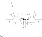
- Fig. 1 taken, which is illustrated by a schematic representation of a first embodiment of a total designated by the reference numeral 1 solar module assembly.
- the solar module arrangement 1 comprises a solar module 2 serving for the photovoltaic conversion of sunlight into electrical power, for example a thin-film solar module, with a plurality of series-connected, integrated solar cells.
- the solar module can be based for example on the so-called substrate configuration. In this case, it has a glass substrate with a thin-film layered structure formed thereon which forms a heterojunction (pn-junction).
- the layer structure may comprise a back electrode layer arranged on the substrate, a photovoltaically active absorber layer made of a doped semiconductor, a buffer layer, as well as a front electrode layer transparent to radiation in the visible spectral range.
- the layer structure is usually sealed with a sunlight-transparent cover plate.
- the solar module includes 2 a first terminal contact and a second terminal contact, which may be formed in the form of metal strips, for example, and are electrically connected to one another by the solar cells connected in series.
- the solar module assembly 1 further comprises two junction boxes 3, 4 for interconnecting the solar module 2 with an electrical load, in particular for the serial connection of the solar module 2 with other solar modules.
- a first junction box 3 via an electrical conductor, not shown, for example, a flat conductor which is connected to a first pole terminal 5 of the first junction box 3, electrically connected to the first terminal contact of the solar module 2.
- the electrical conductor may be performed for this purpose, for example, through a bore of the substrate of the solar module.
- a second junction box 4 via an electrical conductor, not shown, which is connected to a second pole terminal 6 of the second junction box 4, electrically connected to the second terminal contact of the solar module 2.
- two further electrical conductors are connected to the two pole terminals 5, 6, namely in the first junction box 3, a first female connection 7, through which the first pole terminal 5 is electrically conductively connected to a first connector socket 9, and a first cable connection 16, by which the first pole terminal 5 is electrically conductively connected to a first connection cable 14, and in the second connection box 4 a second socket connection 8, by which the second pole terminal 6 is electrically conductively connected to a second connection socket 10 and a second Cable connection 17, through which the second Pole terminal 6 is electrically connected to a second connecting cable 15.
- the two connecting cables 14, 15 serve to connect the solar module 2 to an electrical load.
- the two junction boxes 3, 4 are electrically connected to each other via a diode cable 13, for which purpose the diode cable 13 is provided at its two ends with connector 11, not shown.
- the diode cable 13 is thus connected by the inserted into the sockets 9, 10 connector 11, 12 via detachable electrical connectors with the two junction boxes 3, 4.
- the diode cable 13 includes a freewheeling diode 18, which is connected in antiparallel to the solar module 2. By the freewheeling diode 18 prevents the solar module 2, for example, in the case of shading or module defect damaged by reverse polarity and the shaded solar module is bridged.
- the solar module assembly 1 can be fitted or retrofitted in a simple manner by inserting the diode cable 13 in the junction boxes 3, 4 with the freewheeling diode 18.
- the freewheeling diode 18 can be used optionally and demand-dependent, whereby the manufacturing cost of the solar module assembly 1 can be reduced.
- a simple replacement of the freewheeling diode 18 is made possible in case of a functional failure.
- Not least subject to arranged in the diode cable 13 freewheeling diode 18 is an efficient cooling.
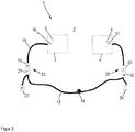
- FIG. 2 taken, wherein a schematic representation of a second embodiment of the solar module assembly 1 is illustrated. To avoid unnecessary repetition, only the differences become the in Fig. 1 illustrated first embodiment and otherwise made to the statements made there reference.
- the solar module assembly 1 comprises two junction boxes 3, 4, which have a first pole terminal 5 and second pole terminal 6, which are electrically conductively connected to the first terminal contact or second terminal contact of the solar module 2.
- first pole terminal 5 and second pole terminal 6, which are electrically conductively connected to the first terminal contact or second terminal contact of the solar module 2.
- first cable connection 16 connected to the first pole terminal 5, which is electrically conductively connected to the first connection cable 14, and a second cable connection 17 connected to the second pole terminal 6, which is electrically conductively connected to the second connection cable 15.
- the two connection cables 14, 15 are electrically conductively connected via a first plug connection 25 or a second plug connection 26 to the diode cable 13 containing the free-wheeling diode 18.
- the two connectors 25, 26 are each composed of a releasably interconnected plug-in part and plug-in part, wherein the plug-in part here, for example, as a male plug (M) and the plug-in part as a female connector (F) are formed.
- the first connection cable 14 is provided at its free end with a first plug-in part 19 and the second connection cable 15 at its free end with a first plug-in part 20.
- the diode cable 13 bifurcates at its two ends, in each case a plug-in part and a plug-in part are arranged at both ends.
- one end of the diode cable 13 is provided with a second plug-in part 21, which forms the first plug-in connection 25 together with the first plug-in part 19, and the other end of the diode cable 13 is provided with a second plug-in part 22, which together with the first plug-in part 20 second connector 26 forms.
- Parallel to the second plug-in part 21, a third plug-in part 23 is connected to the diode cable 13.
- Parallel to the second plug-in part 22, a third plug-in part 24 is connected to the diode cable 13.
- the third plug-in part 23 and the third plug-in part 24 can be used for the serial connection of the solar module 2 with further solar modules serve.
- the solar module assembly 1 can be fitted or retrofitted in a particularly simple manner with the diode 18, without providing a special configuration for the two connecting cables 14, 15.
- the plug-in parts 22, 23 or plug-in parts 21, 24 of the diode cable 13 may be provided with a Verpolêt, which prevents the free-wheeling diode 18 is connected in a faulty manner in the forward direction to the solar module 2.
- the plug-in parts or plug-in parts may be provided for this purpose, for example, with a color coding or be characterized by their special shape. It is also conceivable, however, any other suitable identification of the plug-in parts or plug-in parts.
- the invention provides a solar module arrangement in which a freewheeling diode connected in antiparallel to the solar module is arranged outside the junction boxes, so that the freewheeling diode can be used as required. This allows a saving of costs and a simple assembly or retrofitting of the solar module assembly with the freewheeling diode.
- the freewheeling diode or the diode cable can be certified independently of the solar module.
Landscapes
- Photovoltaic Devices (AREA)
- Life Sciences & Earth Sciences (AREA)
- Sustainable Development (AREA)
Description
- Die Erfindung betrifft nach ihrer Gattung eine Solarmodulanordnung nach dem Oberbegriff des unabhängigen Patentanspruchs.
- Solarmodule zur photovoltaischen Umwandlung von Sonnenlicht in elektrische Leistung werden zunehmend zur Energieerzeugung eingesetzt. Hinsichtlich des Wirkungsgrads haben sich Dünnschichtsolarmodule auf Basis polykristalliner Chalkopyrit-Halbleiter als vorteilhaft erwiesen, wobei sich insbesondere Kupfer-Indium-Diselenid (CuInSe2 bzw. CIS) aufgrund seines an das Spektrum des Sonnenlichts angepassten Bandabstands durch einen besonders hohen Absorptionskoeffizienten auszeichnet. Da mit einzelnen Solarzellen nur Spannungspegel von weniger als 1 Volt erreichbar sind, werden in der Regel mehrere Solarzellen in einem Solarmodul seriell verschaltet, um auf diese Weise eine technisch brauchbare Ausgangsspannung zu erhalten. Dabei bieten Dünnschichtsolarmodule den besonderen Vorteil, dass die Solarzellen schon während der Schichtenherstellung in integrierter Form seriell verschaltet werden können. In der Patentliteratur wurden Dünnschichtsolarmodule bereits mehrfach beschrieben. Lediglich beispielhaft sei auf die Patentschrift
DE 4324318 C1 verwiesen. - Für einen Anschluss an eine elektrische Last verfügen Solarmodule über zumindest eine Anschlussdose, die typischer Weise auf der Rückseite des Solarmoduls angebracht ist. Die Anschlussdose enthält Anschlusskontakte. Die elektrische Verbindung zwischen den Anschlusskontakten und der Solarzellenschaltung wird beispielsweise in Form von Metallbändern von der Solarzellenschaltung aus dem Modul heraus in die Anschlussdose geführt. In der praktischen Anwendung werden oft mehrere Solarmodule durch an die Anschlussdosen angeschlossene Anschlusskabel zu einem Modulstrang in Reihe verschaltet. Hierbei ist es bekannt, für jedes Modul eine Freilauf- bzw. Bypassdiode vorzusehen, die mit den Anschlusskontakten des Solarmoduls so verschaltet ist, dass sie im normalen Betriebszustand, in dem das Modul Strom liefert, in Sperrrichtung gepolt ist. Durch die antiparallel geschalteten Freilaufdioden kann eine Beschädigung von Solarmodulen oder durch Überbrückung der zeitlich begrenzte Ausfall des Modulstrangs zur Stromerzeugung verhindert werden, falls diese beispielsweise aufgrund einer Verschattung oder eines Moduldefekts keinen Strom liefern, da der von den anderen Solarmodulen gelieferte Strom über die Freilaufdiode fließen kann.
- Die japanische Druckschrift
JP 7 131045 A EP 1 585 178 A1 undWO 2009/137347 A2 entnommen werden. - Demgegenüber besteht die Aufgabe der vorliegenden Erfindung darin, herkömmliche Solarmodule in vorteilhafter Weise weiterzubilden, wobei insbesondere die Fertigung vereinfacht und Herstellungskosten verringert werden sollen. Diese und weitere Aufgaben werden nach dem Vorschlag der Erfindung durch eine Solarmodulanordnung mit den Merkmalen des unabhängigen Patentanspruchs gelöst. Vorteilhafte Ausgestaltungen der Erfindung sind durch die Merkmale der Unteransprüche angegeben.
- Gemäß der Erfindung ist eine Solarmodulanordnung gezeigt, die ein Solarmodul zur photovoltaischen Energieerzeugung umfasst. Typischer Weise ist das Solarmodul mit einer Mehrzahl in Reihe verschalteter Solarzellen versehen. Bei dem Solarmodul kann es sich um ein kristallines, multikristallines Silizium-Solarmodul oder um ein Dünnschichtsolarmodul mit integrierten, seriell verschalteten Solarzellen handeln. Insbesondere kann die Halbleiterschicht aus einer Chalkopyrit-Verbindung bestehen, bei der es sich beispielsweise um einen I-III-VI-Halbleiter aus der Gruppe Kupfer-Indium/Gallium-Dischwefel/Diselenid (Cu(InGa) (SSE)2), beispielsweise Kupfer-Indium-Diselenid (CuInSe2 bzw. CIS) oder verwandte Verbindungen, um Cadmium-Tellurid und / oder Dünnschichtsilizium handeln kann.
- Die Solarmodulanordnung umfasst weiterhin ein an das Solarmodul angeschlossenes erstes Anschlussgehäuse und ein an das Solarmodul angeschlossenes zweites Anschlussgehäuse zur Verbindung des Solarmoduls mit einer elektrischen Last.
- In der erfindungsgemäßen Solarmodulanordnung ist weiterhin eine zum Solarmodul antiparallel verschaltete Freilauf- bzw. Bypassdiode vorgesehen, durch die ein Schutz des Solarmoduls bei fehlender Stromerzeugung beispielsweise infolge von Verschattung erreicht wird. Die beiden Anschlusskontakte des Solarmoduls sind zu diesem Zweck über die in Sperrrichtung verschaltete Freilaufdiode elektrisch miteinander verbunden.
- Wesentlich hierbei ist, dass die Freilaufdiode in einem die beiden Anschlussgehäuse elektrisch miteinander verbindenden Diodenkabel enthalten ist. Somit kann durch das Diodenkabel auch im Falle zweier Anschlussgehäuse wahlfrei und bedarfsabhängig eine einfache Bestückung bzw. Nachrüstung der Solarmodulanordnung mit der Freilaufdiode erreicht werden.
- Unter dem Begriff "Diodenkabel" wird hier und im Weiteren ein eine Diode enthaltendes biegsames Kabel, aber auch eine Diode enthaltendes, starres und an die Anschlussdosen ansteckbares Modul, verstanden. Ohne besondere Vorkenntnisse sind die Diodenkabel funktionsgemäß mit den Anschlussgehäusen dauerhaft und vor Umwelteinflüssen geschützt verbindbar.
- Ein biegsames Kabel ist hierbei ein mit einer elektrischen I-solatorhülle ummantelter, bevorzugt einadriger Verbund von Drähten, welcher ein gleichförmiges oder ein in regelmäßigen Abständen wiederkehrendes gleichförmiges Querschnittsprofil aufweist.
- Durch diese Maßnahme kann in vorteilhafter Weise erreicht werden, dass die Diode wahlfrei und bedarfsabhängig in die Solarmodulanordnung eingebaut werden kann und insbesondere in Anwendungen, bei denen eine Verschattung des Solarmoduls nicht zu erwarten ist, nicht eingesetzt wird. Dies ermöglicht eine einfache und kostengünstige Herstellung der Solarmodulanordnung. Zudem kann die Solarmodulanordnung in vorteilhafter Weise nachträglich, d. h. nach Herstellung und insbesondere wenn diese schon in der jeweiligen Anwendung in Stellung gebracht worden ist, mit der Freilaufdiode bestückt werden. Ein weiterer Vorteil der Erfindung ergibt sich auch aus der Tatsache, dass Solarmodule gemäß DIN EN 61646 zertifiziert werden müssen, so dass die Freilaufdiode bzw. das Diodenkabel separat zertifizierbar sind, wodurch in der industriellen Serienfertigung in erheblichem Umfang Kosten eingespart werden können. Weitere Vorteile der Erfindung ergeben sich aus der Beschreibung der konkreten Ausführungsbeispiele.
- Bei einer vorteilhaften Ausgestaltung der erfindungsgemäßen Solarmodulanordnung ist das Diodenkabel über eine Kupplung, die ein mit einem Kupplungsgegenteil lösbar verbundenes Kupplungsteil umfasst, mit den beiden Anschlussgehäusen elektrisch verbunden, wodurch eine besonders einfache Bestückung, insbesondere Nachrüstung, der Solarmodulanordnung mit der Freilaufdiode ermöglicht ist. Zudem kann das Diodenkabel besonders einfach mit den Anschlussgehäusen verbunden werden. Dabei kann die Freilaufdiode auch in einer der beiden Kupplungen enthalten sein.
- Das Diodenkabel wird vorzugsweise zur Verbindung von Solarmodulen einer Solarmodulanordnung in einem Flächen- oder Dachbereich eingesetzt, auf dem die Sonneneinstrahlung zeitweise oder dauerhaft abgeschattet ist. Abgeschattete Bereiche befinden sich insbesondere im Umfeld von baulichen Einrichtungen wie Kaminen, Antennen, Dachvorbauten und anderen Gebäuden oder im Bereich von Bäumen. Die erfindungsgemäße Solarmodulanordnung kann durch Diodenkabel auf veränderte Beschattungsverhältnisse angepasst werden. Das Diodenkabel kann als optionales Bauelement in einfacher Weise nachgerüstet werden.
- Eine alternative Ausgestaltung der erfindungsgemäßen Solarmodulanordnung umfasst vorzugsweise mindestens zwei Solarmodule, wobei die Anschlussgehäuse von mindestens einem der Solarmodule durch ein Diodenkabel verbunden sind.
- Bei einer weiteren vorteilhaften Ausgestaltung der Solarmodulanordnung sind die beiden Anschlussgehäuse jeweils mit einem Anschlusskabel zur Verbindung des Solarmoduls mit einer elektrischen Last versehen, wobei das Diodenkabel mit den beiden Anschlusskabeln elektrisch leitend verbunden ist. Diese Ausgestaltung kann technisch besonders einfach realisiert werden, wobei das Diodenkabel zum einfachen Anbringen über Kupplungen, die jeweils ein mit einem Kupplungsgegenteil lösbar verbundenes Kupplungsteil umfassen, mit den beiden Anschlusskabeln elektrisch verbunden sein kann. Dabei kann die Freilaufdiode auch in einer der beiden Kupplungen enthalten sein.
- Vorteilhaft ist das Diodenkabel an seinen beiden Enden jeweils mit einem Kupplungsteil und einem Kupplungsgegenteil versehen, so dass einerseits eine Verbindung der beiden Anschlusskabel unter Zwischenschaltung der Freilaufdiode und andererseits eine Verbindung der Anschlusskabel mit einer elektrischen Last in einfacher Weise erreicht werden kann, ohne dabei konstruktive Veränderungen an den Anschlusskabeln vornehmen zu müssen. Hierbei ist es von Vorteil, wenn die Kupplungsteile und Kupplungsgegenteile des Diodenkabels jeweils mit einer Verpolsicherung zum Verhindern einer parallelen Verschaltung der Freilaufdiode mit dem Solarmodul versehen sind. Durch diese Maßnahme kann eine fehlerhafte Verschaltung der Freilaufdiode verhindert werden. Eine solche Verpolsicherung kann beispielsweise durch eine spezielle Farb- und/oder Formgebung der Kupplungsteile und/oder Kupplungsgegenteile des Diodenkabels verkörpert sein.
- Gezeigt ist auch ein Diodenkabel zur Verwendung bei einer Solarmodulanordnung zu antiparallelen Verschalten der Diode gezeigt, welches an seinen beiden Enden jeweils mit einem Kupplungsteil und einem Kupplungsgegenteil versehen ist. Vorteilhaft sind die Kupplungsteile und/oder Kupplungsgegenteile jeweils mit einer Verpolsicherung zum Verhindern einer zum Solarmodul parallelen Verschaltung der Diode versehen, die durch eine spezielle Farb- und/oder Formgebung der Kupplungsteile beziehungsweise Kupplungsgegenteile verkörpert sein kann.
- Die Erfindung wird nun anhand von Ausführungsbeispielen näher erläutert, wobei Bezug auf die beigefügten Figuren genommen wird. Es zeigen:
- Fig. 1
- eine schematische Darstellung eines ersten Ausführungsbeispiels der erfindungsgemäßen Solarmodulanordnung;
- Fig. 2
- eine schematische Darstellung eines zweiten Ausführungsbeispiels der erfindungsgemäßen Solarmodulanordnung.
- Sei zunächst Bezug auf
Fig. 1 genommen, worin anhand einer schematischen Darstellung ein erstes Ausführungsbeispiel für eine insgesamt mit der Bezugszahl 1 bezeichnete Solarmodulanordnung veranschaulicht ist. - Die Solarmodulanordnung 1 umfasst ein zur photovoltaischen Umwandlung von Sonnenlicht in elektrische Leistung dienendes Solarmodul 2, beispielsweise Dünnschichtsolarmodul, mit einer Mehrzahl seriell verschalteter, integrierter Solarzellen. Das Solarmodul kann beispielsweise auf der so genannten Substratkonfiguration basieren. In diesem Fall verfügt es über ein gewöhnlich aus Glas bestehendes Substrat mit einem darauf aufgebrachten Schichtenaufbau aus dünnen Schichten, der einen Heteroübergang (pn-Übergang) bildet. Zu diesem Zweck kann der Schichtenaufbau eine auf dem Substrat angeordnete Rückelektrodenschicht, eine photovoltaisch aktive Absorberschicht aus einem dotierten Halbleiter, eine Pufferschicht, sowie eine für Strahlung im sichtbaren Spektralbereich transparente Frontelektrodenschicht umfassen. Zum Schutz vor Umwelteinflüssen ist der Schichtenaufbau in der Regel mit einer für Sonnenlicht transparenten Deckplatte versiegelt. Weiterhin umfasst das Solarmodul 2 einen ersten Anschlusskontakt und einen zweiten Anschlusskontakt, die beispielsweise in Form von Metallbändern ausgebildet sein können und durch die in Reihe verschalteten Solarzellen elektrisch miteinander verbunden sind.
- Der grundsätzliche Aufbau eines solchen Solarmoduls 2 ist dem Fachmann, beispielsweise aus der eingangs genannten Druckschrift, an sich wohlbekannt, so dass hier nicht näher darauf eingegangen werden muss. Im Übrigen ist er für das Verständnis der Erfindung nicht wesentlich, aus welchem Grund das Solarmodul 2 in den Figuren nicht näher dargestellt ist.
- Die Solarmodulanordnung 1 umfasst weiterhin zwei Anschlussdosen 3, 4 zur Verschaltung des Solarmoduls 2 mit einer elektrischen Last, insbesondere zur seriellen Verschaltung des Solarmoduls 2 mit anderen Solarmodulen. Hierbei ist eine erste Anschlussdose 3 über einen nicht näher dargestellten elektrischen Leiter, beispielsweise ein Flachleiter, der mit einer ersten Polklemme 5 der ersten Anschlussdose 3 verbunden ist, mit dem ersten Anschlusskontakt des Solarmoduls 2 elektrisch leitend verbunden. Der elektrische Leiter kann zu diesem Zweck beispielsweise durch eine Bohrung des Substrats des Solarmoduls hindurch geführt sein. In entsprechender Weise ist eine zweite Anschlussdose 4 über einen nicht näher dargestellten elektrischen Leiter, der mit einer zweiten Polklemme 6 der zweiten Anschlussdose 4 verbunden ist, mit dem zweiten Anschlusskontakt des Solarmoduls 2 elektrisch leitend verbunden.
- Innerhalb der beiden Anschlussdosen 3, 4 sind an die beiden Polklemmen 5, 6 jeweils zwei weitere elektrische Leiter angeschlossen, nämlich in der ersten Anschlussdose 3 eine erste Buchsenverbindung 7, durch die die erste Polklemme 5 mit einer ersten Anschlussbuchse 9 elektrisch leitend verbunden ist, und eine erste Kabelverbindung 16, durch die die erste Polklemme 5 mit einem ersten Anschlusskabel 14 elektrisch leitend verbunden ist, sowie in der zweiten Anschlussdose 4 eine zweite Buchsenverbindung 8, durch die die zweite Polklemme 6 mit einer zweiten Anschlussbuchse 10 elektrisch leitend verbunden ist und eine zweite Kabelverbindung 17, durch die die zweite Polklemme 6 mit einem zweiten Anschlusskabel 15 elektrisch leitend verbunden ist. Wie bereits erwähnt, dienen die beiden Anschlusskabel 14, 15 dienen zum Anschließen des Solarmoduls 2 an eine elektrische Last.
- Die beiden Anschlussdosen 3, 4 sind über ein Diodenkabel 13 elektrisch miteinander verbunden, zu welchem Zweck das Diodenkabel 13 an seinen beiden Enden mit nicht näher dargestellten Anschlussstecker 11, 12 versehen ist. Das Diodenkabel 13 ist somit durch die in die Anschlussbuchsen 9, 10 eingesteckten Anschlussstecker 11, 12 über lösbare elektrische Steckverbindungen mit den beiden Anschlussdosen 3, 4 verbunden. Das Diodenkabel 13 enthält eine Freilaufdiode 18, die antiparallel zum Solarmodul 2 verschaltet ist. Durch die Freilaufdiode 18 wird verhindert, dass das Solarmodul 2 beispielsweise im Falle einer Verschattung oder eines Moduldefekts durch Verpolung beschädigt und das verschattete Solarmodul überbrückt wird. Die Solarmodulanordnung 1 kann in einfacher Weise durch Einstecken des Diodenkabels 13 in die Anschlussdosen 3, 4 mit der Freilaufdiode 18 bestückt bzw. nachgerüstet werden. Somit kann die Freilaufdiode 18 wahlfrei und bedarfsabhängig eingesetzt werden, wodurch die Herstellungskosten für die Solarmodulanordnung 1 vermindert werden können. Zudem ist ein einfacher Austausch der Freilaufdiode 18 etwa bei einem Funktionsausfall ermöglicht. Nicht zuletzt unterliegt die im Diodenkabel 13 angeordnete Freilaufdiode 18 einer effizienten Kühlung.
- Obgleich dies in
Fig. 1 nicht gezeigt ist, kann in einer Modifikation der Solarmodulanordnung 1 das Diodenkabel 13 mit einer Dioden in einem starren Gehäuse ohne zweite Anschlussdose 4 direkt mit dem zweiten Anschlusskontakt des Solarmoduls 2 elektrisch leitend verbunden sein. Eine solche Solarmodulanordnung 1 umfasst demnach lediglich eine einzige Anschlussdose 3. - Es wird nun Bezug auf
Fig. 2 genommen, worin anhand einer schematischen Darstellung ein zweites Ausführungsbeispiel der Solarmodulanordnung 1 veranschaulicht ist. Um unnötige Wiederholungen zu vermeiden, werden lediglich die Unterschiede zu dem inFig. 1 gezeigten ersten Ausführungsbeispiel erläutert und ansonsten auf die dort gemachten Ausführungen Bezug genommen. - Demnach umfasst die Solarmodulanordnung 1 zwei Anschlussdosen 3, 4, die über eine erste Polklemme 5 bzw. zweite Polklemme 6 verfügen, die mit dem ersten Anschlusskontakt bzw. zweiten Anschlusskontakt des Solarmoduls 2 elektrisch leitend verbunden sind. Von den beiden Polklemmen 5, 6 geht jeweils nur eine einzige elektrische Leitung ab. Dies sind eine mit der ersten Polklemme 5 verbundene erste Kabelverbindung 16, die mit dem ersten Anschlusskabel 14 elektrisch leitend verbunden ist, sowie eine mit der zweiten Polklemme 6 verbundene zweite Kabelverbindung 17, die mit dem zweiten Anschlusskabel 15 elektrisch leitend verbunden ist. Die beiden Anschlusskabel 14, 15 sind über eine erste Steckverbindung 25 bzw. eine zweite Steckverbindung 26 mit dem die Freilaufdiode 18 enthaltenden Diodenkabel 13 elektrisch leitend verbunden. Die beiden Steckverbindungen 25, 26 sind jeweils aus einem lösbar miteinander verbundenen Steckteil und Steckgegenteil zusammengesetzt, wobei das Steckteil hier beispielsweise als männlicher Stecker (M) und das Steckgegenteil als weiblicher Stecker (F) ausgebildet sind. Zu diesem Zweck ist das erste Anschlusskabel 14 an seinem freien Ende mit einem ersten Steckteil 19 und das zweite Anschlusskabel 15 an seinem freien Ende mit einem ersten Steckgegenteil 20 versehen. Das Diodenkabel 13 gabelt sich an seinen beiden Enden jeweils auf, wobei an beiden Enden jeweils ein Steckteil und ein Steckgegenteil angeordnet sind. So ist das eine Ende des Diodenkabels 13 mit einem zweiten Steckgegenteil 21 versehen, das gemeinsam mit dem ersten Steckteil 19 die erste Steckverbindung 25 formt, und das andere Ende des Diodenkabels 13 mit einem zweiten Steckteil 22 versehen, das gemeinsam mit dem ersten Steckgegenteil 20 die zweite Steckverbindung 26 formt. Parallel zum zweiten Steckgegenteil 21 ist ein drittes Steckteil 23 an das Diodenkabel 13 angeschlossen. Parallel zum zweiten Steckteil 22 ist ein drittes Steckgegenteil 24 an das Diodenkabel 13 angeschlossen. Das dritte Steckteil 23 und das dritte Steckgegenteil 24 können zur seriellen Verschaltung des Solarmoduls 2 mit weiteren Solarmodulen dienen. Durch das Diodenkabel 13 kann die Solarmodulanordnung 1 in besonders einfacher Weise mit der Diode 18 bestückt bzw. nachgerüstet werden, ohne für die beiden Anschlusskabel 14, 15 ein spezielle Konfiguration vorzusehen.
- Die Steckteile 22, 23 bzw. Steckgegenteile 21, 24 des Diodenkabels 13 können mit einer Verpolsicherung versehen sein, durch die verhindert wird, dass die Freilaufdiode 18 in fehlerhafter Weise in Durchlassrichtung mit dem Solarmodul 2 verschaltet wird. Die Steckteile bzw. Steckgegenteile können zu diesem Zweck beispielsweise mit einer Farbkodierung versehen sein oder durch ihre spezielle Formgebung gekennzeichnet sein. Denkbar ist aber auch jede andere geeignete Kennzeichnung der Steckteile bzw. Steckgegenteile.
- Die Erfindung stellt eine Solarmodulanordnung zur Verfügung, bei der eine antiparallel zum Solarmodul verschaltete Freilaufdiode außerhalb der Anschlussdosen angeordnet ist, so dass die Freilaufdiode bedarfsgerecht eingesetzt werden kann. Dies ermöglicht eine Einsparung von Kosten und eine einfache Bestückung bzw. Nachrüstung der Solarmodulanordnung mit der Freilaufdiode. Zudem kann die Freilaufdiode bzw. das Diodenkabel unabhängig vom Solarmodul zertifiziert werden.
-
- 1
- Solarmodulanordnung
- 2
- Solarmodul
- 3
- erste Anschlussdose
- 4
- zweite Anschlussdose
- 5
- erste Polklemme
- 6
- zweite Polklemme
- 7
- erste Buchsenverbindung
- 8
- zweite Buchsenverbindung
- 9
- erste Anschlussbuchse
- 10
- zweite Anschlussbuchse
- 11
- erster Anschlussstecker
- 12
- zweiter Anschlussstecker
- 13
- Diodenkabel
- 14
- erstes Anschlusskabel
- 15
- zweites Anschlusskabel
- 16
- erste Kabelverbindung
- 17
- zweite Kabelverbindung
- 18
- Freilaufdiode
- 19
- erstes Steckteil
- 20
- erstes Steckgegenteil
- 21
- zweites Steckgegenteil
- 22
- zweites Steckteil
- 23
- drittes Steckteil
- 24
- drittes Steckgegenteil
- 25
- erste Steckverbindung
- 26
- zweite Steckverbindung
Claims (9)
- Solarmodulanordnung (1), welche umfasst:ein Solarmodul (2) zur photovoltaischen Energieerzeugung mit einer Mehrzahl in Reihe verschalteter Solarzellen, mit einem ersten Anschlusskontakt und einem zweiten Anschlusskontakt, die durch die in Reihe verschalteten Solarzellen elektrisch miteinander verbunden sind,ein an das Solarmodul (2) angeschlossenes erstes Anschlussgehäuse (3) zur Verbindung des Solarmoduls (2) mit einer elektrischen Last, welches mit dem ersten Anschlusskontakt elektrisch verbunden ist,ein an das Solarmodul (2) angeschlossenes zweites Anschlussgehäuse (4) zur Verbindung des Solarmoduls (2) mit einer elektrischen Last, welches mit dem zweiten Anschlusskontakt elektrisch verbunden ist,eine zum Solarmodul (2) antiparallel verschaltete Freilaufdiode (18),wobei die Freilaufdiode (18) in einem die beiden Anschlussgehäuse (3, 4) elektrisch miteinander verbindenden Diodenkabel (13) enthalten ist.
- Solarmodulanordnung (1) nach Anspruch 1, wobei das Diodenkabel (13) ein biegsames Kabel enthält.
- Solarmodulanordnung (1) nach einem der Ansprüche 1 oder 2, wobei das Diodenkabel (13) jeweils über eine Kupplung (9, 11, 10, 12), die ein mit einem Kupplungsgegenteil (9, 10) lösbar verbundenes Kupplungsteil (11, 12) umfasst, mit den beiden Anschlussgehäusen (3, 4) elektrisch verbunden ist.
- Solarmodulanordnung (1) nach Anspruch 3, wobei die Freilaufdiode (18) in einer der beiden Kupplungen (9, 11, 10, 12) enthalten ist.
- Solarmodulanordnung (1) nach einem der Ansprüche 1 oder 3, wobei die beiden Anschlussgehäuse (3, 4) jeweils mit einem Anschlusskabel (14, 15) zur Verbindung des Solarmoduls (2) mit einer elektrischen Last versehen sind, wobei das Diodenkabel (13) mit den beiden Anschlusskabeln (14, 15) elektrisch leitend verbunden ist.
- Solarmodulanordnung (1) nach Anspruch 5, wobei das Diodenkabel (13) über Kupplungen (25, 26), die jeweils ein mit einem Kupplungsgegenteil (20, 21) lösbar verbundenes Kupplungsteil (19, 22) umfassen, mit den beiden Anschlusskabeln (14, 15) elektrisch verbunden ist.
- Solarmodulanordnung (1) nach Anspruch 6, wobei die Freilaufdiode (18) in einer der beiden Kupplungen (25, 26) enthalten ist.
- Solarmodulanordnung nach einem der Ansprüche 6 oder 7, wobei das Diodenkabel (13) an seinen beiden Enden jeweils mit einem Kupplungsteil (22, 23) und einem Kupplungsgegenteil (20, 21) versehen ist.
- Solarmodulanordnung (1) nach Anspruch 8, wobei die Kupplungsteile (22, 23) und Kupplungsgegenteile (20, 21) des Diodenkabels (13) jeweils mit einer Verpolsicherung zum Verhindern einer parallelen Verschaltung der Freilaufdiode (18) mit dem Solarmodul (2) versehen sind.
Priority Applications (1)
| Application Number | Priority Date | Filing Date | Title |
|---|---|---|---|
| EP11702417.4A EP2529412B1 (de) | 2010-01-29 | 2011-01-27 | Solarmodulanordnungen und diodenkabel |
Applications Claiming Priority (3)
| Application Number | Priority Date | Filing Date | Title |
|---|---|---|---|
| EP10152088A EP2352178A1 (de) | 2010-01-29 | 2010-01-29 | Solarmodulanordnungen und Diodenkabel |
| EP11702417.4A EP2529412B1 (de) | 2010-01-29 | 2011-01-27 | Solarmodulanordnungen und diodenkabel |
| PCT/EP2011/051129 WO2011092237A2 (de) | 2010-01-29 | 2011-01-27 | Solarmodulanordnungen und diodenkabel |
Publications (2)
| Publication Number | Publication Date |
|---|---|
| EP2529412A2 EP2529412A2 (de) | 2012-12-05 |
| EP2529412B1 true EP2529412B1 (de) | 2019-08-07 |
Family
ID=42235584
Family Applications (2)
| Application Number | Title | Priority Date | Filing Date |
|---|---|---|---|
| EP10152088A Withdrawn EP2352178A1 (de) | 2010-01-29 | 2010-01-29 | Solarmodulanordnungen und Diodenkabel |
| EP11702417.4A Active EP2529412B1 (de) | 2010-01-29 | 2011-01-27 | Solarmodulanordnungen und diodenkabel |
Family Applications Before (1)
| Application Number | Title | Priority Date | Filing Date |
|---|---|---|---|
| EP10152088A Withdrawn EP2352178A1 (de) | 2010-01-29 | 2010-01-29 | Solarmodulanordnungen und Diodenkabel |
Country Status (9)
| Country | Link |
|---|---|
| US (1) | US9018518B2 (de) |
| EP (2) | EP2352178A1 (de) |
| JP (1) | JP2013518423A (de) |
| KR (1) | KR101502670B1 (de) |
| CN (1) | CN102714248B (de) |
| EA (1) | EA201290721A1 (de) |
| ES (1) | ES2753501T3 (de) |
| WO (1) | WO2011092237A2 (de) |
| ZA (1) | ZA201205388B (de) |
Families Citing this family (10)
| Publication number | Priority date | Publication date | Assignee | Title |
|---|---|---|---|---|
| EP2769418A1 (de) * | 2011-10-19 | 2014-08-27 | Saint-Gobain Glass France | Solarmodul mit flachbandleiter, sowie verfahren zu dessen herstellung |
| US8581242B2 (en) * | 2012-02-21 | 2013-11-12 | Atomic Energy Council—Institute of Nuclear Energy Research | Apparatus combining bypass diode and wire |
| DE102014017157B3 (de) * | 2014-11-20 | 2016-01-28 | Caetec Gmbh | Thermoleitung und Modulblock zur Verbindung mit einem Thermomesssystem |
| JP6660061B2 (ja) | 2014-12-16 | 2020-03-04 | エービービー シュヴァイツ アクチェンゲゼルシャフト | エネルギーパネル装置の電力消費 |
| US10348094B2 (en) | 2015-01-28 | 2019-07-09 | Abb Schweiz Ag | Energy panel arrangement shutdown |
| ES2832823T3 (es) | 2015-02-22 | 2021-06-11 | Marici Holdings The Netherlands Bv | Detección de polaridad inversa de cadenas fotovoltaicas |
| US20190229674A1 (en) * | 2015-10-22 | 2019-07-25 | Eterbright Solar Corporation | Solar Panel Module and Solar Panel Apparatus |
| US12040742B2 (en) * | 2019-05-15 | 2024-07-16 | Xplor Llc | Scalable solar modular array |
| DE102021122010A1 (de) * | 2021-08-25 | 2023-03-02 | Weidmüller Interface GmbH & Co. KG | Photovoltaikmodul und Anschlussanordnung für ein Photovoltaikmodul |
| CN115967347A (zh) * | 2023-02-15 | 2023-04-14 | 常熟市福莱德连接器科技有限公司 | 一种新型连接器 |
Family Cites Families (16)
| Publication number | Priority date | Publication date | Assignee | Title |
|---|---|---|---|---|
| JPH07131045A (ja) * | 1993-06-23 | 1995-05-19 | Kubota Corp | 太陽電池発電装置用電装部材 |
| DE4324318C1 (de) | 1993-07-20 | 1995-01-12 | Siemens Ag | Verfahren zur Serienverschaltung einer integrierten Dünnfilmsolarzellenanordnung |
| JPH10135504A (ja) * | 1996-10-31 | 1998-05-22 | Tokyo Electric Power Co Inc:The | 太陽電池モジュール配線用コネクタとその接続方法 |
| JP2001148493A (ja) * | 1999-11-19 | 2001-05-29 | Sumitomo Wiring Syst Ltd | 太陽電池パネル用のコネクタ装置 |
| JP2001339088A (ja) * | 2000-05-26 | 2001-12-07 | Kyocera Corp | 太陽電池装置 |
| JP2002009326A (ja) * | 2000-06-26 | 2002-01-11 | Kanegafuchi Chem Ind Co Ltd | 二極防水コネクタ及びこれを用いた太陽電池モジュールの配線構造 |
| JP2003078155A (ja) * | 2001-09-05 | 2003-03-14 | Canon Inc | 太陽電池アレイの形成方法 |
| WO2004064165A1 (ja) * | 2001-10-12 | 2004-07-29 | Mitsubishi Heavy Industries, Ltd. | 太陽電池モジュール集合体、配線システム及び太陽光発電システム |
| CN2612074Y (zh) * | 2003-02-24 | 2004-04-14 | 上海行田电产有限公司 | 太阳电池模块连接用端子盒装置 |
| JP2005183660A (ja) * | 2003-12-19 | 2005-07-07 | Canon Inc | 太陽電池モジュール |
| US7432439B2 (en) * | 2004-03-12 | 2008-10-07 | Mitsubishi Denki Kabushiki Kaisha | Terminal box |
| US7697247B2 (en) * | 2006-11-10 | 2010-04-13 | Abb Technology Ag | Arc suppression circuit using a semi-conductor switch |
| DE102007027159A1 (de) * | 2007-03-20 | 2008-09-25 | Webasto Ag | Solarzellenmodul |
| CA2723395C (en) * | 2008-05-05 | 2014-11-25 | Dow Global Technologies Inc. | Photovoltaic device assembly and method |
| JP2009295615A (ja) * | 2008-06-02 | 2009-12-17 | Furukawa Electric Co Ltd:The | 車載用太陽電池モジュール |
| JP2010205805A (ja) * | 2009-02-27 | 2010-09-16 | Mitsubishi Heavy Ind Ltd | 太陽電池パネル |
-
2010
- 2010-01-29 EP EP10152088A patent/EP2352178A1/de not_active Withdrawn
-
2011
- 2011-01-27 US US13/519,576 patent/US9018518B2/en active Active
- 2011-01-27 JP JP2012550439A patent/JP2013518423A/ja active Pending
- 2011-01-27 KR KR1020127019854A patent/KR101502670B1/ko active Active
- 2011-01-27 ES ES11702417T patent/ES2753501T3/es active Active
- 2011-01-27 CN CN201180007398.6A patent/CN102714248B/zh active Active
- 2011-01-27 EP EP11702417.4A patent/EP2529412B1/de active Active
- 2011-01-27 WO PCT/EP2011/051129 patent/WO2011092237A2/de not_active Ceased
- 2011-01-27 EA EA201290721A patent/EA201290721A1/ru unknown
-
2012
- 2012-07-18 ZA ZA2012/05388A patent/ZA201205388B/en unknown
Non-Patent Citations (1)
| Title |
|---|
| None * |
Also Published As
| Publication number | Publication date |
|---|---|
| US9018518B2 (en) | 2015-04-28 |
| ZA201205388B (en) | 2013-04-24 |
| WO2011092237A2 (de) | 2011-08-04 |
| EA201290721A1 (ru) | 2013-01-30 |
| KR101502670B1 (ko) | 2015-03-13 |
| EP2529412A2 (de) | 2012-12-05 |
| CN102714248A (zh) | 2012-10-03 |
| CN102714248B (zh) | 2017-05-03 |
| US20120285502A1 (en) | 2012-11-15 |
| EP2352178A1 (de) | 2011-08-03 |
| KR20120138740A (ko) | 2012-12-26 |
| JP2013518423A (ja) | 2013-05-20 |
| ES2753501T3 (es) | 2020-04-08 |
| WO2011092237A3 (de) | 2012-07-19 |
Similar Documents
| Publication | Publication Date | Title |
|---|---|---|
| WO2011092237A2 (de) | Solarmodulanordnungen und diodenkabel | |
| DE112016003768B4 (de) | Sonnenkollektor | |
| DE202013012612U1 (de) | Kabelmodul für Modulwechselrichter eines Photovoltaikgenerators | |
| EP2533303A2 (de) | Solarmodul und Photovoltaik-Anlage | |
| DE102014118332A1 (de) | Photovoltaikmodul | |
| DE202012004526U1 (de) | Photovoltaikmodul | |
| DE112016003818T5 (de) | Photovoltaikerzeugungssystem und Verfahren zur Verwendung desselben | |
| DE102011052928A1 (de) | Anordnung mit einem Solarzellenmodul, einer Anschlussdose, einem Anschlussstecker und einer Anschlussleitung | |
| DE202025106235U1 (de) | Photovoltaikmodul | |
| WO2013097964A1 (de) | Solarzellenanordnung in tandem-konfiguration | |
| DE102010043006A1 (de) | Photovoltaisches Bauelement | |
| DE202013010384U1 (de) | Photovoltaikmodul und sein integrierter Rahmen | |
| DE202011001341U1 (de) | Photovoltaikmoudul mit einlaminierter Bypassdiode | |
| WO2011092239A1 (de) | Solarzellenanordnung und dünnschichtsolarmodul, sowie herstellungsverfahren hierfür | |
| EP2533302A2 (de) | Solarmodul und Photovoltaik-Anlage | |
| WO2024061746A1 (de) | Solarmodul mit 3-terminal-tandem-solarzellen | |
| DE202012100662U1 (de) | Solarmodul mit Anschlusselementen | |
| DE102011079505A1 (de) | Solarzellenbaustein und Solarzellenanordnung | |
| EP3573110A1 (de) | Solarmodul mit vergrösserter aperturfläche | |
| EP2769418A1 (de) | Solarmodul mit flachbandleiter, sowie verfahren zu dessen herstellung | |
| DE102021112969A1 (de) | Solarzellenmodul | |
| DE102009033357A1 (de) | Beschichtungssystem | |
| WO2021078976A1 (de) | Photovoltaikmodul und photovoltaikanlage sowie verfahren zum betrieb einer solchen | |
| DE112023000232T5 (de) | Kabeleinheit | |
| WO2023006833A1 (de) | Mehradriger anschlussverbinder für photovoltaikmodule |
Legal Events
| Date | Code | Title | Description |
|---|---|---|---|
| PUAI | Public reference made under article 153(3) epc to a published international application that has entered the european phase |
Free format text: ORIGINAL CODE: 0009012 |
|
| 17P | Request for examination filed |
Effective date: 20120817 |
|
| AK | Designated contracting states |
Kind code of ref document: A2 Designated state(s): AL AT BE BG CH CY CZ DE DK EE ES FI FR GB GR HR HU IE IS IT LI LT LU LV MC MK MT NL NO PL PT RO RS SE SI SK SM TR |
|
| DAX | Request for extension of the european patent (deleted) | ||
| REG | Reference to a national code |
Ref country code: DE Ref legal event code: R079 Ref document number: 502011015972 Country of ref document: DE Free format text: PREVIOUS MAIN CLASS: H01L0031048000 Ipc: H01L0031050000 |
|
| RIC1 | Information provided on ipc code assigned before grant |
Ipc: H01L 31/05 20140101AFI20171215BHEP Ipc: H02S 40/34 20140101ALI20171215BHEP Ipc: H02S 40/36 20140101ALI20171215BHEP |
|
| RIN1 | Information on inventor provided before grant (corrected) |
Inventor name: PHILIPP, JAN BORIS |
|
| GRAP | Despatch of communication of intention to grant a patent |
Free format text: ORIGINAL CODE: EPIDOSNIGR1 |
|
| STAA | Information on the status of an ep patent application or granted ep patent |
Free format text: STATUS: GRANT OF PATENT IS INTENDED |
|
| INTG | Intention to grant announced |
Effective date: 20181120 |
|
| RIC1 | Information provided on ipc code assigned before grant |
Ipc: H01L 31/05 20140101AFI20171215BHEP Ipc: H02S 40/36 20140101ALI20171215BHEP Ipc: H02S 40/34 20140101ALI20171215BHEP |
|
| GRAS | Grant fee paid |
Free format text: ORIGINAL CODE: EPIDOSNIGR3 |
|
| GRAA | (expected) grant |
Free format text: ORIGINAL CODE: 0009210 |
|
| STAA | Information on the status of an ep patent application or granted ep patent |
Free format text: STATUS: THE PATENT HAS BEEN GRANTED |
|
| AK | Designated contracting states |
Kind code of ref document: B1 Designated state(s): AL AT BE BG CH CY CZ DE DK EE ES FI FR GB GR HR HU IE IS IT LI LT LU LV MC MK MT NL NO PL PT RO RS SE SI SK SM TR |
|
| RAP1 | Party data changed (applicant data changed or rights of an application transferred) |
Owner name: (CNBM) BENGBU DESIGN & RESEARCH INSTITUTE FOR GLAS |
|
| REG | Reference to a national code |
Ref country code: GB Ref legal event code: FG4D Free format text: NOT ENGLISH |
|
| REG | Reference to a national code |
Ref country code: CH Ref legal event code: EP Ref country code: AT Ref legal event code: REF Ref document number: 1165161 Country of ref document: AT Kind code of ref document: T Effective date: 20190815 |
|
| REG | Reference to a national code |
Ref country code: DE Ref legal event code: R096 Ref document number: 502011015972 Country of ref document: DE |
|
| REG | Reference to a national code |
Ref country code: IE Ref legal event code: FG4D Free format text: LANGUAGE OF EP DOCUMENT: GERMAN |
|
| REG | Reference to a national code |
Ref country code: NL Ref legal event code: MP Effective date: 20190807 |
|
| REG | Reference to a national code |
Ref country code: LT Ref legal event code: MG4D |
|
| PG25 | Lapsed in a contracting state [announced via postgrant information from national office to epo] |
Ref country code: SE Free format text: LAPSE BECAUSE OF FAILURE TO SUBMIT A TRANSLATION OF THE DESCRIPTION OR TO PAY THE FEE WITHIN THE PRESCRIBED TIME-LIMIT Effective date: 20190807 Ref country code: LT Free format text: LAPSE BECAUSE OF FAILURE TO SUBMIT A TRANSLATION OF THE DESCRIPTION OR TO PAY THE FEE WITHIN THE PRESCRIBED TIME-LIMIT Effective date: 20190807 Ref country code: BG Free format text: LAPSE BECAUSE OF FAILURE TO SUBMIT A TRANSLATION OF THE DESCRIPTION OR TO PAY THE FEE WITHIN THE PRESCRIBED TIME-LIMIT Effective date: 20191107 Ref country code: NL Free format text: LAPSE BECAUSE OF FAILURE TO SUBMIT A TRANSLATION OF THE DESCRIPTION OR TO PAY THE FEE WITHIN THE PRESCRIBED TIME-LIMIT Effective date: 20190807 Ref country code: HR Free format text: LAPSE BECAUSE OF FAILURE TO SUBMIT A TRANSLATION OF THE DESCRIPTION OR TO PAY THE FEE WITHIN THE PRESCRIBED TIME-LIMIT Effective date: 20190807 Ref country code: PT Free format text: LAPSE BECAUSE OF FAILURE TO SUBMIT A TRANSLATION OF THE DESCRIPTION OR TO PAY THE FEE WITHIN THE PRESCRIBED TIME-LIMIT Effective date: 20191209 Ref country code: FI Free format text: LAPSE BECAUSE OF FAILURE TO SUBMIT A TRANSLATION OF THE DESCRIPTION OR TO PAY THE FEE WITHIN THE PRESCRIBED TIME-LIMIT Effective date: 20190807 Ref country code: NO Free format text: LAPSE BECAUSE OF FAILURE TO SUBMIT A TRANSLATION OF THE DESCRIPTION OR TO PAY THE FEE WITHIN THE PRESCRIBED TIME-LIMIT Effective date: 20191107 |
|
| PG25 | Lapsed in a contracting state [announced via postgrant information from national office to epo] |
Ref country code: LV Free format text: LAPSE BECAUSE OF FAILURE TO SUBMIT A TRANSLATION OF THE DESCRIPTION OR TO PAY THE FEE WITHIN THE PRESCRIBED TIME-LIMIT Effective date: 20190807 Ref country code: IS Free format text: LAPSE BECAUSE OF FAILURE TO SUBMIT A TRANSLATION OF THE DESCRIPTION OR TO PAY THE FEE WITHIN THE PRESCRIBED TIME-LIMIT Effective date: 20191207 Ref country code: AL Free format text: LAPSE BECAUSE OF FAILURE TO SUBMIT A TRANSLATION OF THE DESCRIPTION OR TO PAY THE FEE WITHIN THE PRESCRIBED TIME-LIMIT Effective date: 20190807 Ref country code: GR Free format text: LAPSE BECAUSE OF FAILURE TO SUBMIT A TRANSLATION OF THE DESCRIPTION OR TO PAY THE FEE WITHIN THE PRESCRIBED TIME-LIMIT Effective date: 20191108 Ref country code: RS Free format text: LAPSE BECAUSE OF FAILURE TO SUBMIT A TRANSLATION OF THE DESCRIPTION OR TO PAY THE FEE WITHIN THE PRESCRIBED TIME-LIMIT Effective date: 20190807 |
|
| PG25 | Lapsed in a contracting state [announced via postgrant information from national office to epo] |
Ref country code: TR Free format text: LAPSE BECAUSE OF FAILURE TO SUBMIT A TRANSLATION OF THE DESCRIPTION OR TO PAY THE FEE WITHIN THE PRESCRIBED TIME-LIMIT Effective date: 20190807 |
|
| REG | Reference to a national code |
Ref country code: ES Ref legal event code: FG2A Ref document number: 2753501 Country of ref document: ES Kind code of ref document: T3 Effective date: 20200408 |
|
| PG25 | Lapsed in a contracting state [announced via postgrant information from national office to epo] |
Ref country code: DK Free format text: LAPSE BECAUSE OF FAILURE TO SUBMIT A TRANSLATION OF THE DESCRIPTION OR TO PAY THE FEE WITHIN THE PRESCRIBED TIME-LIMIT Effective date: 20190807 Ref country code: EE Free format text: LAPSE BECAUSE OF FAILURE TO SUBMIT A TRANSLATION OF THE DESCRIPTION OR TO PAY THE FEE WITHIN THE PRESCRIBED TIME-LIMIT Effective date: 20190807 Ref country code: RO Free format text: LAPSE BECAUSE OF FAILURE TO SUBMIT A TRANSLATION OF THE DESCRIPTION OR TO PAY THE FEE WITHIN THE PRESCRIBED TIME-LIMIT Effective date: 20190807 Ref country code: PL Free format text: LAPSE BECAUSE OF FAILURE TO SUBMIT A TRANSLATION OF THE DESCRIPTION OR TO PAY THE FEE WITHIN THE PRESCRIBED TIME-LIMIT Effective date: 20190807 |
|
| PG25 | Lapsed in a contracting state [announced via postgrant information from national office to epo] |
Ref country code: IS Free format text: LAPSE BECAUSE OF FAILURE TO SUBMIT A TRANSLATION OF THE DESCRIPTION OR TO PAY THE FEE WITHIN THE PRESCRIBED TIME-LIMIT Effective date: 20200224 Ref country code: SM Free format text: LAPSE BECAUSE OF FAILURE TO SUBMIT A TRANSLATION OF THE DESCRIPTION OR TO PAY THE FEE WITHIN THE PRESCRIBED TIME-LIMIT Effective date: 20190807 Ref country code: CZ Free format text: LAPSE BECAUSE OF FAILURE TO SUBMIT A TRANSLATION OF THE DESCRIPTION OR TO PAY THE FEE WITHIN THE PRESCRIBED TIME-LIMIT Effective date: 20190807 Ref country code: SK Free format text: LAPSE BECAUSE OF FAILURE TO SUBMIT A TRANSLATION OF THE DESCRIPTION OR TO PAY THE FEE WITHIN THE PRESCRIBED TIME-LIMIT Effective date: 20190807 |
|
| REG | Reference to a national code |
Ref country code: DE Ref legal event code: R097 Ref document number: 502011015972 Country of ref document: DE |
|
| PLBE | No opposition filed within time limit |
Free format text: ORIGINAL CODE: 0009261 |
|
| STAA | Information on the status of an ep patent application or granted ep patent |
Free format text: STATUS: NO OPPOSITION FILED WITHIN TIME LIMIT |
|
| PG2D | Information on lapse in contracting state deleted |
Ref country code: IS |
|
| 26N | No opposition filed |
Effective date: 20200603 |
|
| PG25 | Lapsed in a contracting state [announced via postgrant information from national office to epo] |
Ref country code: SI Free format text: LAPSE BECAUSE OF FAILURE TO SUBMIT A TRANSLATION OF THE DESCRIPTION OR TO PAY THE FEE WITHIN THE PRESCRIBED TIME-LIMIT Effective date: 20190807 Ref country code: MC Free format text: LAPSE BECAUSE OF FAILURE TO SUBMIT A TRANSLATION OF THE DESCRIPTION OR TO PAY THE FEE WITHIN THE PRESCRIBED TIME-LIMIT Effective date: 20190807 |
|
| REG | Reference to a national code |
Ref country code: CH Ref legal event code: PL |
|
| REG | Reference to a national code |
Ref country code: BE Ref legal event code: MM Effective date: 20200131 |
|
| PG25 | Lapsed in a contracting state [announced via postgrant information from national office to epo] |
Ref country code: LU Free format text: LAPSE BECAUSE OF NON-PAYMENT OF DUE FEES Effective date: 20200127 |
|
| PG25 | Lapsed in a contracting state [announced via postgrant information from national office to epo] |
Ref country code: BE Free format text: LAPSE BECAUSE OF NON-PAYMENT OF DUE FEES Effective date: 20200131 Ref country code: CH Free format text: LAPSE BECAUSE OF NON-PAYMENT OF DUE FEES Effective date: 20200131 Ref country code: LI Free format text: LAPSE BECAUSE OF NON-PAYMENT OF DUE FEES Effective date: 20200131 |
|
| PG25 | Lapsed in a contracting state [announced via postgrant information from national office to epo] |
Ref country code: IE Free format text: LAPSE BECAUSE OF NON-PAYMENT OF DUE FEES Effective date: 20200127 |
|
| REG | Reference to a national code |
Ref country code: AT Ref legal event code: MM01 Ref document number: 1165161 Country of ref document: AT Kind code of ref document: T Effective date: 20200127 |
|
| PG25 | Lapsed in a contracting state [announced via postgrant information from national office to epo] |
Ref country code: AT Free format text: LAPSE BECAUSE OF NON-PAYMENT OF DUE FEES Effective date: 20200127 |
|
| REG | Reference to a national code |
Ref country code: DE Ref legal event code: R082 Ref document number: 502011015972 Country of ref document: DE |
|
| PG25 | Lapsed in a contracting state [announced via postgrant information from national office to epo] |
Ref country code: MT Free format text: LAPSE BECAUSE OF FAILURE TO SUBMIT A TRANSLATION OF THE DESCRIPTION OR TO PAY THE FEE WITHIN THE PRESCRIBED TIME-LIMIT Effective date: 20190807 Ref country code: CY Free format text: LAPSE BECAUSE OF FAILURE TO SUBMIT A TRANSLATION OF THE DESCRIPTION OR TO PAY THE FEE WITHIN THE PRESCRIBED TIME-LIMIT Effective date: 20190807 |
|
| PG25 | Lapsed in a contracting state [announced via postgrant information from national office to epo] |
Ref country code: MK Free format text: LAPSE BECAUSE OF FAILURE TO SUBMIT A TRANSLATION OF THE DESCRIPTION OR TO PAY THE FEE WITHIN THE PRESCRIBED TIME-LIMIT Effective date: 20190807 |
|
| REG | Reference to a national code |
Ref country code: DE Ref legal event code: R079 Ref document number: 502011015972 Country of ref document: DE Free format text: PREVIOUS MAIN CLASS: H01L0031050000 Ipc: H10F0019900000 |
|
| PGFP | Annual fee paid to national office [announced via postgrant information from national office to epo] |
Ref country code: GB Payment date: 20260107 Year of fee payment: 16 |
|
| PGFP | Annual fee paid to national office [announced via postgrant information from national office to epo] |
Ref country code: ES Payment date: 20260226 Year of fee payment: 16 |
|
| PGFP | Annual fee paid to national office [announced via postgrant information from national office to epo] |
Ref country code: DE Payment date: 20260121 Year of fee payment: 16 |
|
| PGFP | Annual fee paid to national office [announced via postgrant information from national office to epo] |
Ref country code: IT Payment date: 20260122 Year of fee payment: 16 |
|
| PGFP | Annual fee paid to national office [announced via postgrant information from national office to epo] |
Ref country code: FR Payment date: 20260107 Year of fee payment: 16 |