EP2527583B1 - Concealment system comprising an apron which comprises a device for limiting the folding of the apron - Google Patents
Concealment system comprising an apron which comprises a device for limiting the folding of the apron Download PDFInfo
- Publication number
- EP2527583B1 EP2527583B1 EP12305578.2A EP12305578A EP2527583B1 EP 2527583 B1 EP2527583 B1 EP 2527583B1 EP 12305578 A EP12305578 A EP 12305578A EP 2527583 B1 EP2527583 B1 EP 2527583B1
- Authority
- EP
- European Patent Office
- Prior art keywords
- apron
- retractable stop
- movable element
- closing system
- folding
- Prior art date
- Legal status (The legal status is an assumption and is not a legal conclusion. Google has not performed a legal analysis and makes no representation as to the accuracy of the status listed.)
- Active
Links
- 230000000903 blocking effect Effects 0.000 claims description 35
- 241000255925 Diptera Species 0.000 claims description 6
- 230000005484 gravity Effects 0.000 claims description 5
- 210000000056 organ Anatomy 0.000 claims 2
- 230000000284 resting effect Effects 0.000 claims 1
- 230000000694 effects Effects 0.000 description 21
- 238000010276 construction Methods 0.000 description 10
- 238000006073 displacement reaction Methods 0.000 description 10
- 238000004519 manufacturing process Methods 0.000 description 4
- 238000004804 winding Methods 0.000 description 3
- 230000002950 deficient Effects 0.000 description 2
- 238000012423 maintenance Methods 0.000 description 2
- 230000004048 modification Effects 0.000 description 2
- 238000012986 modification Methods 0.000 description 2
- 210000002445 nipple Anatomy 0.000 description 2
- 230000003313 weakening effect Effects 0.000 description 2
- 238000001816 cooling Methods 0.000 description 1
- 238000005553 drilling Methods 0.000 description 1
- 238000002513 implantation Methods 0.000 description 1
- 238000009434 installation Methods 0.000 description 1
- 230000001846 repelling effect Effects 0.000 description 1
- 238000005096 rolling process Methods 0.000 description 1
- 238000011144 upstream manufacturing Methods 0.000 description 1
Images


Classifications
-
- E—FIXED CONSTRUCTIONS
- E06—DOORS, WINDOWS, SHUTTERS, OR ROLLER BLINDS IN GENERAL; LADDERS
- E06B—FIXED OR MOVABLE CLOSURES FOR OPENINGS IN BUILDINGS, VEHICLES, FENCES OR LIKE ENCLOSURES IN GENERAL, e.g. DOORS, WINDOWS, BLINDS, GATES
- E06B9/00—Screening or protective devices for wall or similar openings, with or without operating or securing mechanisms; Closures of similar construction
- E06B9/56—Operating, guiding or securing devices or arrangements for roll-type closures; Spring drums; Tape drums; Counterweighting arrangements therefor
- E06B9/80—Safety measures against dropping or unauthorised opening; Braking or immobilising devices; Devices for limiting unrolling
- E06B9/82—Safety measures against dropping or unauthorised opening; Braking or immobilising devices; Devices for limiting unrolling automatic
-
- E—FIXED CONSTRUCTIONS
- E06—DOORS, WINDOWS, SHUTTERS, OR ROLLER BLINDS IN GENERAL; LADDERS
- E06B—FIXED OR MOVABLE CLOSURES FOR OPENINGS IN BUILDINGS, VEHICLES, FENCES OR LIKE ENCLOSURES IN GENERAL, e.g. DOORS, WINDOWS, BLINDS, GATES
- E06B9/00—Screening or protective devices for wall or similar openings, with or without operating or securing mechanisms; Closures of similar construction
- E06B9/02—Shutters, movable grilles, or other safety closing devices, e.g. against burglary
- E06B9/08—Roll-type closures
- E06B9/11—Roller shutters
- E06B9/17—Parts or details of roller shutters, e.g. suspension devices, shutter boxes, wicket doors, ventilation openings
- E06B9/17046—Bottom bars
-
- E—FIXED CONSTRUCTIONS
- E06—DOORS, WINDOWS, SHUTTERS, OR ROLLER BLINDS IN GENERAL; LADDERS
- E06B—FIXED OR MOVABLE CLOSURES FOR OPENINGS IN BUILDINGS, VEHICLES, FENCES OR LIKE ENCLOSURES IN GENERAL, e.g. DOORS, WINDOWS, BLINDS, GATES
- E06B9/00—Screening or protective devices for wall or similar openings, with or without operating or securing mechanisms; Closures of similar construction
- E06B9/02—Shutters, movable grilles, or other safety closing devices, e.g. against burglary
- E06B9/08—Roll-type closures
- E06B9/11—Roller shutters
- E06B9/15—Roller shutters with closing members formed of slats or the like
- E06B2009/1577—Slat end pieces used for guiding shutter
- E06B2009/1583—Slat end pieces used for guiding shutter inserted in slat cavity
-
- E—FIXED CONSTRUCTIONS
- E06—DOORS, WINDOWS, SHUTTERS, OR ROLLER BLINDS IN GENERAL; LADDERS
- E06B—FIXED OR MOVABLE CLOSURES FOR OPENINGS IN BUILDINGS, VEHICLES, FENCES OR LIKE ENCLOSURES IN GENERAL, e.g. DOORS, WINDOWS, BLINDS, GATES
- E06B9/00—Screening or protective devices for wall or similar openings, with or without operating or securing mechanisms; Closures of similar construction
- E06B9/24—Screens or other constructions affording protection against light, especially against sunshine; Similar screens for privacy or appearance; Slat blinds
- E06B9/40—Roller blinds
- E06B9/42—Parts or details of roller blinds, e.g. suspension devices, blind boxes
-
- E—FIXED CONSTRUCTIONS
- E06—DOORS, WINDOWS, SHUTTERS, OR ROLLER BLINDS IN GENERAL; LADDERS
- E06B—FIXED OR MOVABLE CLOSURES FOR OPENINGS IN BUILDINGS, VEHICLES, FENCES OR LIKE ENCLOSURES IN GENERAL, e.g. DOORS, WINDOWS, BLINDS, GATES
- E06B9/00—Screening or protective devices for wall or similar openings, with or without operating or securing mechanisms; Closures of similar construction
- E06B9/52—Devices affording protection against insects, e.g. fly screens; Mesh windows for other purposes
- E06B9/54—Roller fly screens
Definitions
- the present invention relates to a device for limiting the folding of the apron of a closure system, at the end of the folding race of this apron.
- the invention also relates to a closing system apron comprising a final blade and such a limiting device.
- the invention relates to a closing system of an opening of a construction and comprising such an apron.
- the present invention relates to the field of the building and, more particularly, that of the manufacture of systems designed to ensure the closure of an opening defined at a construction.
- a closure system can be constituted by a shutter, a mosquito net, a blind, a garage door or other.
- This invention relates, more particularly, to a closure system incorporating a device for limiting the folding of the apron that includes such a closure system.
- the document EP-0092122 discloses a closure system comprising an apron and lateral slides within which slide the lateral ends of this apron.
- This closure system comprises, again, a device for limiting the folding of the apron.
- This limiting device comprises, inside at least one slide, a support means for interrupting the folding of the apron.
- This limitation device comprises, again, a support engaged inside a lateral end of a blade of the apron of the closure system and a movable member rotatably mounted relative to said support.
- this movable element is provided with a retractable abutment capable of occupying, by rotation of said movable element, an active position in which this abutment retractable can cooperate with the support means to interrupt the folding of the apron at the end of the apron folding stroke, an inactive position in which the retractable stop is cleared with respect to this support means and thus allows the continuation of the folding the apron beyond the end position, this in order to more easily remove the apron blocked high abutment in the event of a failure of the drive motor of a shaft which is associated with said apron.
- this limitation device also comprises a means for locking the retractable stop in its active position.
- this locking means is constituted by a removable pin designed to cooperate with a plurality of holes in the movable member.
- this pin cooperates with a first piercing of the movable element.
- the pin is removed from the first hole to engage in a second hole (perpendicular to the first hole) before acting on the pin to rotate the movable member. Access to this second bore and the rotational drive of the movable member are permitted due to the presence of a notch in the final plate of the deck.
- EP-0092122 presents, however, a plurality of disadvantages.
- this device comprises a pin which constitutes an additional element to the closure system and which is therefore added to the many parts that include such a system.
- this pin is an essential element for both locking and unlocking the retractable stop so that in the absence of this pin it is impossible to lock or unlock the stop.
- this pin is removable type so that during manufacture, installation, manipulation or intervention on the closure system, this pin is likely to to escape from its piercing or to be voluntarily removed from this piercing with a significant risk of losing this pin resulting in the disadvantages mentioned above.
- the final blade of the apron has a slot whose presence has the effect of weakening the final blade and reduce its resistance to a stress exerted on it either by wind or as part of an attempted break-in.
- This device comprises a support made integral with a deck blade and an element movable relative to this support, and secured to a final blade of this deck.
- This device also comprises a retractable abutment, which comprises the movable element, and which can occupy, on the one hand, an active locking position in which this abutment cooperates with a support means to interrupt the folding of the apron and on the other hand, an inactive blocking position in which this stop is erased relative to this support means to allow the folding of the apron.
- This device also comprises a means for mounting the movable element sliding relative to the support and a means for mounting the retractable stop in displacement relative to the movable element, this between the active position of blocking and inactive blocking position.
- the device described in the document EP-0242317 is designed to prevent the folding of the apron of a closure system, this when the apron adopts a fully deployed position and in the case of an attempted burglary consisting in exerting, under the final blade of the deck, a pressure towards the high, more particularly by levering on this final blade. Consequently, this device constitutes an anti-lifting device of the apron which, in the context of a normal folding / unfolding maneuver of this apron, comprises a retractable stop adopting an inactive position of blocking thus making it possible, in no way, to limit the folding of the apron at the end of the folding race of this apron.
- a pressure exerted upwards and on the final blade brings the retractable stopper into an active locking position preventing, then, the continued folding of the deck beyond the end position (especially inside a box) and thus making it much more difficult dismantling the apron blocked high abutment, this in the case of a maintenance or repair operation of the closure system.
- This system comprises an apron comprising a final blade, lateral slides inside which move the lateral ends of the apron, and a device for limiting the folding of the apron at the end of the apron folding stroke.
- This device comprises a support provided with means for receiving the final blade of the deck and a movable element relative to this support.
- This device also comprises a retractable abutment which, at the end of the folding stroke of the apron, can occupy, on the one hand, and in the absence of intervention on the limitation device, an active locking position in which this abutment cooperates with a support means that comprises at least one of the slides, this to interrupt the folding of the deck, and, on the other hand and under the effect of an intervention on the limiting device, an inactive blocking position in which this stop is erased with respect to this support means, this to allow the continuation of the folding of the apron beyond the end position.
- This device also comprises means for locking the retractable stop in the active blocking position.
- This device also comprises a means for mounting the movable element sliding relative to the support and a means for mounting the retractable stop in displacement relative to the movable element, this between the active position of blocking and inactive blocking position.
- the object of the present invention is to overcome the drawbacks of limitation devices of the state of the art.
- This closure system is characterized in that the movable element comprises the retractable stop while the locking means of the retractable stop is constituted by the support which, by sliding of the movable element relative to the support, can occupy, on the one hand, a locking position of the retractable stop in the active locking position and, on the other hand, an unlocking position of this retractable stop.
- the device for limiting the folding of the deck according to the invention comprises a means of locking the retractable stop constituted by the support that incorporates this device.
- this locking means is, therefore, an integral part of the device and in no way constitutes a removable part that can be lost or lost.
- the limiting device according to the invention comprises a support, a movable element and a retractable stop.
- This device consequently comprises, and advantageously, a limited number of parts.
- these parts have a simple shape, easily achievable and reproducible, and requiring no additional intervention as a drilling operation for parts of the state of the art.
- these parts are designed and arranged so as to be able to move relative to each other in accordance with simple movements (sliding, rotation) and in a simplified kinematics advantageously to make reliable the operation of this device.
- Another advantage is that mounting the limiting device on the closure system simply involves engaging a portion of this device within the final blade. Such an assembly requires no modification of the deck of this closure system, including a modification that would lead to weaken this deck as is the case for devices of the state of the art. This apron retains, therefore advantageously, all its features, including its rigidity.
- the retractable stop adopts an active blocking position, this in the absence of particular intervention on the closure system and, in particular, in the absence of intervention on the apron or on the device for limiting the folding. This allows, at the end of the apron folding stroke and in the absence of such intervention, to limit the folding of the apron and, thus, prevent the complete engagement of this apron inside a box and / or the release of this apron out of the guide slides.
- the retractable stop can adopt an inactive blocking position, this under the effect of intervention (manual) on the closure system, in particular under the effect of an intervention on the limitation device, more particularly on the retractable stop. Also and under the effect of such an intervention, the retractable stop adopts an inactive position of blocking allowing the continuation of the folding of the deck beyond the end position, more particularly in order to push the deck completely to the end. inside a box and / or extract the apron out of its guide slides, especially in the context of a maintenance operation or repair of the closure system.
- the retractable stop is locked in its active locking position which allows this retractable abutment always ensure a limitation of the folding of the apron at the end of the race of folding of this apron.
- Unlocking the retractable stop is made simply by ensuring the sliding of the movable member relative to the support (or support relative to the movable member), more particularly by exerting pressure upwards and on this support.
- This sliding is, in fact, controlled by a simple intervention (manual) on the final telescopic blade of the deck and consisting of pushing the movable section of the final blade towards the fixed profile of the final blade.
- This unlocking allows, then and at the end of the apron folding stroke, to make (manually) adopt the retractable stop an inactive blocking position.
- the limiting device according to the invention can equip a closure system directly during its manufacture but also after, especially after implantation of this closure system at the construction.
- the present invention relates to the field of manufacturing systems 1 designed to ensure the closure of a defined opening at a construction.
- such a closure system 1 may be constituted by a roller shutter, a mosquito net, a blind, a garage door or other.
- a closure system 1 consisting of a shutter knowing that the present invention is in no way limited to this embodiment.
- the closure system 1 comprises an apron 2 incorporating at least one blade, or even constituted by an assembly (particularly longitudinally) of a plurality of blades.
- such a deck 2 comprises a final strip 20 constituting a free end of this deck 2.
- This final deck 20 comprises, on the one hand, a fixed section 21 connected to an upstream part of the deck 2, on the other hand, a movable section 22 forming a distal end of this deck 2 and, secondly, a means 23 for mounting the movable section 22 in displacement relative to the fixed section 21.
- such a mounting means 23 is designed to allow a sliding of these sections (21; 22) one (21; 22) relative to the other (22; 21), more particularly by engagement of a such profile (more particularly the movable section 22) partly inside the other section (more particularly the fixed section 21).
- a preferred embodiment of the invention consists in that this mounting means 23 is of the telescopic type.
- the closure system 1 also comprises lateral slides (3; 3 '), implanted on either side of the opening, and usually adopting a "U" section or the like. It is, more particularly, within these lateral slides (3; 3 ') that are engaged and scroll the lateral ends (24; 24') of the deck 2, more particularly the lateral ends of the blades of this deck 2 .
- This closure system 1 comprises, again, an assembly, which the apron 2 is made integral, and designed to ensure the folding and deployment of the apron 2.
- Such an assembly comprises at least one driving means of the deck 2 (in particular in the form of a motor), or even a means (for example in the form of a chain, a belt, a rod or analog) for connecting this drive means to said apron 2.
- such an assembly may comprise a shaft, from which the deck 2 is made integral, on which is folded (more particularly by winding) and from which is deployed (more particularly by unwinding) this deck 2 .
- This assembly comprises, then again, a means for driving said shaft in rotation, in order to ensure the folding or the deployment of the deck 2.
- Such a drive means may be of the manual type or, preferably, of the motorized type (more particularly in the form of an electric motor).
- the closure system 1 may also comprise a box 4, surmounting the lateral slides (3; 3 '), receiving internally the winding / unwinding shaft of the deck 2, and inside which is folded this apron 2.
- this closure system 1 also comprises a device 5 for limiting the folding of the apron 2, this at the end of the folding of this deck 2.
- this limiting device 5 comprises a support 6 provided with a means 60 for receiving the final blade 20 of the apron 2, more particularly for the reception of the mobile section 22 that comprises this final blade. 20.
- this means 60 for receiving the final blade 20 is constituted by a tip, extending laterally relative to the support 6, and intended to be engaged (more particularly by interlocking) and immobilized (more particularly by clamping, in particular through a tight engagement, or by deformation of the profile) within a housing that includes this final blade 20 (more particularly that includes the movable section 22 of the final blade 20).
- the tip is engaged within the housing of the final blade 20, this laterally with respect to this final blade 20.
- the support 6 equips, then, the final blade 20 (and, therefore, the apron 2) and extends laterally with respect to this final blade 20 (and, therefore, with respect to this apron 2), this in the plane in which this final blade 20 extends (and, therefore, this apron 2 ), especially in the deployed position of this apron 2.
- This limiting device 5 further comprises an element 7 movable relative to the support 6.
- This movable element 7 comprises, on the one hand, two side and spaced walls (not shown) and two parallel longitudinal walls (70; 70 '). ) and spaced apart, defining between them (70; 70 ') an internal volume 71 to the movable element 7.
- this movable element 7 comprises a bottom 72, extending in a manner lateral (more particularly perpendicular) from a longitudinal wall 70 and towards the other longitudinal wall 70 ', and defining with this other longitudinal wall 70' an opening 73.
- This movable element 7 may, again, comprise a means for receiving a final blade 20 (more particularly the fixed profile 21 that includes this final blade 20) that comprises the apron 2 of the closure system 1.
- a receiving means may again take the form of a tip, extending laterally relative to this movable member 7, and intended to be engaged (more particularly by interlocking) and immobilized (more particularly by clamping, in particular through a tight fitting, or by deformation of the profile) inside a housing that includes this fixed profile 21 of the final blade 20.
- this movable element 7 may comprise a means 74 for receiving a piece 8 (more particularly in the form of a strip or the like) that comprises the closure system 1 and which is designed to control the orientation of the adjustable blades that comprises the apron 2 of the closing system 1.
- a receiving means can take the form of a housing inside which is engaged and immobilized a free end of said part 8.
- the limiting device 5 comprises means for mounting this mobile element 7 in sliding relative to the support 6.
- Such a sliding mounting means is constituted, on the one hand, by a housing 61, which comprises said support 6, and which receives, internally and in sliding, at least a part of the mobile element 7. As visible on the Figures 4 and 5 , this housing 61 has an opening 62 for the passage of the control part 8 mentioned above.
- this sliding mounting means is constituted by a slider 75, which comprises said movable member 7 (at least partly constituted by such a slider 75), and which is slidably mounted inside the housing 61 of the support 6, this between a retracted position inside this housing 61 ( figure 2 and 4 ) and a deployed position outside the housing 61 ( figure 3 and 5 ).
- the limitation device 5 also comprises a retractable stop 9 which can occupy, on the one hand, and as visible figures 2 and 4 an active blocking position in which this stop 9 cooperates with a bearing means (not shown), consisting of a portion of at least one lateral slide (3; 3 ') or a part of the casing 4, or that comprises at least one such lateral slide (3; 3 ') or this box 4, or that comprises the opening of the construction (more particularly the masonry which defines this opening) or an element associated with this opening.
- a bearing means not shown
- Such cooperation is provided at the end of the folding race of the deck 2, this to interrupt the folding of the deck 2 (more particularly inside said housing 4).
- the retractable stop 9 adopts this active locking position in the absence of intervention (direct or indirect) on the limitation device 5.
- this retractable stop 9 occupies this active locking position at the end of the race. folding of the apron 2 as well as in the normal operation of the apron 2 of the closure system 1, particularly during the folding / unfolding maneuvers of the deck 2.
- this retractable stop 9 may occupy an inactive blocking position in which this stop 9 is erased relative to said support means.
- this retractable stop 9 can occupy such an inactive position blocking end of the folding stroke of the deck 2, this under the effect of intervention (More particularly manual, especially with the aid of a tool) on the limitation device 5, more particularly on the retractable stopper 9.
- intervention Me particularly manual, especially with the aid of a tool
- the retractable stopper 9 advantageously allows to allow the continuation of the folding apron 2 beyond the end position.
- this retractable stop 9 adopts this inactive blocking position outside the normal operation of the deck 2 of the closure system 1, more particularly when it comes to carrying out an intervention on this system 1, particularly in the context of after sales service and / or in case of failure of the drive motor of the deck 2 as will be described below.
- this retractable stop 9 is designed to pass (more particularly by tilting) from the inactive blocking position to the active blocking position, this under the effect of gravity and / or under the effect of a return means (spring or the like) and / or under the action of an action (pressure, repulsion) exerted by the support 6 on this retractable stop 9.
- Such action can be exerted by deployment of the final blade 20, more particularly of the movable section 22 of the final blade 20, this after intervention on the deck 2 (folding beyond its end of folding position) and when the apron 2 or the system is put back into operation
- This action is, more particularly, exerted under the effect of a downward force exerted on the support 6, more particularly via the mobile section 22 of the final blade 20 (in particular under the effect of a traction of extenant exerted on this movable section 22).
- the retractable stop 9 takes the form of a jumper comprising an inner branch 90, an outer branch 91, and a connection member 92 of these two branches (internal 90, external 91). .
- At least the outer branch 91 extends from the connecting member 92 diverging.
- the outer branch 91 has a length greater than the inner branch 90, more particularly to allow the tilting of this retractable stop 9 from the inactive position to the active position, this under the effect of gravity.
- this external branch 91 comprises at least one free end (or even an extension of this free end towards the connecting member 92) shaped bevel to facilitate a support on a support means to interrupt the folding of the apron 2 and / or to allow the support 6 to slide relative to the retractable stop 9 in order to push the latter 9 towards its active position.
- the connecting member 92 comprises a flat portion, which has a common edge with the inner leg 90, and which is designed to rest on the bottom 72 of the movable member 7, this in the active position of the retractable stop 9.
- the mobile element 7 which comprises such a retractable stop 9.
- the inner branch 90 of this retractable stop 9 extends inside the movable member 7 (more particularly within its internal volume 71) while the outer branch 91 extends outside of this movable element 7.
- This retractable stop 9 (more particularly its connecting member 92) then passes through the opening 73 that this movable element 7 has.
- the limitation device 5 comprises, again, a means for mounting the retractable stop 9 in displacement with respect to the movable element 7, this between the active blocking position and the inactive blocking position of this retractable stop 9.
- this means for mounting the retractable abutment 9 in displacement relative to the movable element 7 is constituted by a means for mounting this retractable abutment 9 in rotation relative to this movable element 7.
- this rotational mounting means is designed to allow rotation of the retractable stop 9 about an axis perpendicular to the direction of sliding of the movable member 7 relative to the support 6. This axis is, then, also parallel to the longitudinal walls (70; 70 ') and perpendicular to the side walls of this movable element 7.
- this rotational mounting means is designed to allow free rotation at an angle of between 20 and 40 °, preferably of the order of 30 °.
- the rotational mounting means of the retractable stop 9 relative to the movable member 7 is constituted by means for clipping the retractable stop 9 between the parallel side walls of the element. mobile 7.
- the means for clipping comprise nipples equipping laterally the retractable stop 9 (or respectively the side walls), as well as housings, designed to cooperate with the nipples, and defined in correspondence in the side walls (respectively in the retractable stop 9).
- Yet another feature of the invention consists in that the device 5 for limiting the folding has at least one means 10 for limiting the displacement, at least in rotation and / or in translation, of the retractable stop 9 relative to the moving element 7.
- the means 10 for limiting the displacement in rotation of the retractable abutment 9 with respect to the mobile element 7 comprises at least one finger equipping a longitudinal wall 70 of the movable element 7, extending from this longitudinal wall 70 and in the direction of the retractable stop 9, and against which this retractable stop 9 comes to bear.
- this can be constituted, on the one hand, by at least one tongue equipping the connecting member 92 and extending from this connecting member 92 and towards the bottom 72 of the movable member 7 and, secondly, by at least one housing that comprises the bottom 72 of the movable member 7 and arranged corresponding to such a tab.
- the limiting device 5 comprises means for locking the retractable stop 9 in the active blocking position.
- the means for locking the retractable stop 9 in the active locking position is designed to ensure such locking, this under the effect of gravity and / or under the effect of a means of return (spring or the like) and / or under the effect of a downward force exerted on the support 6, more particularly by means of the movable profile 22 that includes the final blade 20 (in particular under the effect of a traction downward exerted on this movable section 22).
- This locking means advantageously makes it possible to lock the retractable stop 9 in the active blocking position, this at least during the folding operation of the deck 2 (in particular at the end of the folding stroke of the deck 2), or even during all the folding / unfolding maneuvers of this apron 2.
- this locking means of the retractable stop 9 is constituted by the support 6 which, by sliding of the movable element 7 relative to the support 6 (or by sliding of the support 6 relative to the movable element 7), can occupy, on the one hand, a locking position of the retractable stop 9 in the active blocking position ( figures 2 and 4 ) and other part, an unlocking position of this retractable stop 9 ( figures 3 and 5 ).
- this retractable stopper 9 is free in displacement (in rotation) with respect to the movable element 7 and is capable of being brought into an inactive position of blocking ( figures 3 and 5 ), more particularly under the effect of an intervention on the limitation device 5 (more particularly on the retractable stop 9), as mentioned above.
- this locking means (more particularly the support 6) is designed to allow such an unlocking, this under the effect of a pressure exerted upwards and on the support 6, more particularly by the intermediate of the movable section 22 that includes the final blade 20 (in particular under the effect of an upward pressure exerted on the movable section 22).
- the invention relates, then, to a device 5, having the characteristics described above, and designed to ensure the limitation of the folding of the deck 2 of a closure system 1, this at the end of the folding of this deck 2.
- This invention also relates to an apron 2 of closure system 1, more particularly of the shutter type, mosquito net, blind, garage door.
- this apron 2 comprises a final blade 20 comprising a fixed profile 21, a movable profile 22, and a means 23 for mounting the movable profile 22 in displacement (sliding) with respect to the fixed profile 21.
- This apron 2 then also includes a device 5 for limiting the folding of this apron 2 having the characteristics described above.
- this limiting device 5 comprises a support 6 provided with a means 60 for receiving the final blade 20 (more particularly the movable profile 22 of this final blade 20) of the apron 2.
- the means 60 for receiving the final blade 20 is constituted by a tip (extending laterally relative to the support 6, more particularly with respect to the housing 61 of this support 6 ) while this final blade 20 (more particularly its movable section 22) has a housing inside which said tip is engaged and immobilized.
- the movable element 7 which comprises this device 5 for limiting the folding of the apron 2
- the latter 7 is provided with a means 74 for receiving either the final blade 20 (more particularly the fixed profile 21 of this final blade 20) of the apron 2, that is to say a part 8 (more particularly in the form of an illustrated strip Figures 2 to 5 ) for controlling the orientation of adjustable blades that includes the apron 2, as mentioned above.
- the latter 23 is designed to allow sliding of these profiles (21; 22) one (21; 22) by relationship to the other (22; 21).
- This mounting means 23 is constituted by a sliding type mounting means and / or telescopic.
- a closure system 1 for equipping an opening defined at a construction.
- a closure system 1 may be constituted by a shutter, a mosquito net, a blind, a garage door or other.
- the deck 2 has the characteristics described above.
- this apron 2 comprises the limiting device 5 having the characteristics mentioned above.
- At least one of the slides (3; 3 ') and / or the box comprise at least one support means designed to cooperate with the retractable stop 9 in the active blocking position, this to interrupt the folding of the apron 2 at the end of the folding race of this apron 2.
- Another feature is that at least a part of the limitation device 5 (more particularly at least the support 6, the movable member 7 and the retractable stop 9 that comprises the device 5) is positioned and moves to the inside a lateral slide (3; 3 ').
- This invention will find a particular use when it comes to intervene on such a closure system 1 in case of failure of the drive means (more particularly motorized) of the winding shaft / unfolding of the deck 2, more particularly when this apron 2 is in the end of folding position.
- This action is constituted by a pressure exerted upwards and on the movable section 22.
- the movable section 22 drives the support 6 of the limitation device 5 in sliding relative to the mobile element 7. This support 7 then passes from the locking position of the retractable stop 9 ( figures 2 and 4 ) to an unlocking position of this retractable stop ( figure 3 and 5 ).
- the operator causes a tilting of the retractable stop 9 (unlocked) from its active locking position to its inactive blocking position, this in particular by introducing a tool (for example a screwdriver) inside a lateral slide .
- a tool for example a screwdriver
- the operator exerts traction on the deck 2 (in particular on the final strip 20, more particularly on the movable section 22) and / or actuates the drive means of this deck 2.
- the positioning of the retractable stop 9 in its active blocking position and the locking of this retractable stop 9 in its active locking position is done automatically (more particularly by gravity and / or by action on the final blade 20, in particular on the profile mobile 22 of this final blade 20 as described above) at the entrance of the final blade 20 in the lateral slide (3; 3 ').
Landscapes
- Engineering & Computer Science (AREA)
- Structural Engineering (AREA)
- Architecture (AREA)
- Civil Engineering (AREA)
- Specific Sealing Or Ventilating Devices For Doors And Windows (AREA)
- Operating, Guiding And Securing Of Roll- Type Closing Members (AREA)
Description
La présente invention a trait à un dispositif de limitation du repliement du tablier d'un système de fermeture, ceci en fin de course de repliement de ce tablier. L'invention concerne, encore, un tablier de système de fermeture comportant une lame finale ainsi qu'un tel dispositif de limitation. Finalement, l'invention a trait à un système de fermeture d'une ouverture d'une construction et comportant un tel tablier.The present invention relates to a device for limiting the folding of the apron of a closure system, at the end of the folding race of this apron. The invention also relates to a closing system apron comprising a final blade and such a limiting device. Finally, the invention relates to a closing system of an opening of a construction and comprising such an apron.
La présente invention concerne le domaine du bâtiment et, plus particulièrement, celui de la fabrication des systèmes conçus pour assurer la fermeture d'une ouverture définie au niveau d'une construction. En fait, un tel système de fermeture peut être constitué par un volet roulant, une moustiquaire, un store, une porte de garage ou autre. Cette invention concerne, alors, plus particulièrement, un système de fermeture incorporant un dispositif de limitation du repliement du tablier que comporte un tel système de fermeture.The present invention relates to the field of the building and, more particularly, that of the manufacture of systems designed to ensure the closure of an opening defined at a construction. In fact, such a closure system can be constituted by a shutter, a mosquito net, a blind, a garage door or other. This invention relates, more particularly, to a closure system incorporating a device for limiting the folding of the apron that includes such a closure system.
L'on connaît, d'ores et déjà, de tels systèmes de fermeture.Such closure systems are known from now on.
En particulier, le document
Ce dispositif de limitation comporte, à l'intérieur d'au moins une coulisse, un moyen d'appui pour interrompre le repliement du tablier. Ce dispositif de limitation comporte, encore, un support engagé à l'intérieur d'une extrémité latérale d'une lame du tablier du système de fermeture ainsi qu'un élément mobile monté en rotation par rapport audit support. L'extrémité de cet élément mobile est pourvue d'une butée escamotable susceptible d'occuper, par rotation dudit élément mobile, soit une position active dans laquelle cette butée escamotable peut coopérer avec le moyen d'appui pour interrompre le repliement du tablier en fin de course de repliement du tablier, soit une position inactive dans laquelle cette butée escamotable est effacée par rapport à ce moyen d'appui et permet ainsi la poursuite du repliement du tablier au-delà de la position de fin de course, ceci dans le but de démonter plus facilement le tablier bloqué en butée haute dans le cas d'une panne du moteur d'entraînement d'un arbre auquel est associé ledit tablier. Finalement, ce dispositif de limitation comporte, également, un moyen pour le verrouillage de la butée escamotable dans sa position active.This limiting device comprises, inside at least one slide, a support means for interrupting the folding of the apron. This limitation device comprises, again, a support engaged inside a lateral end of a blade of the apron of the closure system and a movable member rotatably mounted relative to said support. The end of this movable element is provided with a retractable abutment capable of occupying, by rotation of said movable element, an active position in which this abutment retractable can cooperate with the support means to interrupt the folding of the apron at the end of the apron folding stroke, an inactive position in which the retractable stop is cleared with respect to this support means and thus allows the continuation of the folding the apron beyond the end position, this in order to more easily remove the apron blocked high abutment in the event of a failure of the drive motor of a shaft which is associated with said apron. Finally, this limitation device also comprises a means for locking the retractable stop in its active position.
En fait, ce moyen de verrouillage est constitué par une goupille amovible conçue pour coopérer avec une pluralité de perçages ménagés dans l'élément mobile. Ainsi, pour assurer le verrouillage de l'élément mobile, cette goupille coopère avec un premier perçage de l'élément mobile. Lorsqu'il s'agit de déverrouiller la butée escamotable, on retire la goupille de ce premier perçage pour l'engager dans un second perçage (perpendiculaire au premier perçage) avant d'agir sur la goupille pour entraîner en rotation l'élément mobile. L'accès à ce second perçage et l'entraînement en rotation de l'élément mobile sont permis grâce à la présence d'une entaille ménagée dans la lame finale du tablier.In fact, this locking means is constituted by a removable pin designed to cooperate with a plurality of holes in the movable member. Thus, to ensure the locking of the movable element, this pin cooperates with a first piercing of the movable element. When it comes to unlock the retractable stop, the pin is removed from the first hole to engage in a second hole (perpendicular to the first hole) before acting on the pin to rotate the movable member. Access to this second bore and the rotational drive of the movable member are permitted due to the presence of a notch in the final plate of the deck.
Le dispositif de limitation décrit dans ce document
Ainsi, selon un premier inconvénient, ce dispositif comporte une goupille qui constitue un élément additionnel au système de fermeture et qui vient donc s'ajouter aux nombreuses pièces que comporte un tel système. De plus, cette goupille constitue un élément indispensable aussi bien au verrouillage qu'au déverrouillage de la butée escamotable de sorte qu'en l'absence de cette goupille il est impossible de verrouiller ou de déverrouiller la butée. En outre, cette goupille est de type amovible de sorte que, lors de la fabrication, de l'installation, de la manipulation ou de l'intervention sur le système de fermeture, cette goupille est susceptible de s'échapper de son perçage ou d'être retirée volontairement de ce perçage avec un risque important de perdre cette goupille entraînant les inconvénients mentionnés ci-dessus.Thus, according to a first drawback, this device comprises a pin which constitutes an additional element to the closure system and which is therefore added to the many parts that include such a system. In addition, this pin is an essential element for both locking and unlocking the retractable stop so that in the absence of this pin it is impossible to lock or unlock the stop. In addition, this pin is removable type so that during manufacture, installation, manipulation or intervention on the closure system, this pin is likely to to escape from its piercing or to be voluntarily removed from this piercing with a significant risk of losing this pin resulting in the disadvantages mentioned above.
On observera, également, que, à chaque interruption du repliement du tablier, l'élément mobile subit, à lui seul, les contraintes de cette interruption du repliement. La présence d'une pluralité de perçages pour la réception d'une goupille a pour effet de fragiliser cet élément mobile qui, sous l'effet de ces contraintes, peut subir des dégradations, voire une rupture, entraînant le blocage de la butée escamotable dans sa position active et l'impossibilité de manipuler cette butée pour l'amener dans sa position inactive.It will also be observed that, at each interruption of the folding of the deck, the movable element alone suffers the constraints of this interruption of folding. The presence of a plurality of holes for the reception of a pin has the effect of weakening this movable element which, under the effect of these constraints, can be damaged or even broken, resulting in the blocking of the retractable abutment in its active position and the impossibility of manipulating this stop to bring it to its inactive position.
Finalement, pour autoriser l'entraînement en rotation de l'élément mobile par la goupille, la lame finale du tablier comporte une fente dont la présence a pour effet de fragiliser cette lame finale et de réduire sa résistance à une contrainte exercée sur celle-ci, soit par le vent, soit dans le cadre d'une tentative d'effraction.Finally, to allow rotation of the movable member by the pin, the final blade of the apron has a slot whose presence has the effect of weakening the final blade and reduce its resistance to a stress exerted on it either by wind or as part of an attempted break-in.
Dans la demande de brevet
En fait, le dispositif décrit dans le document
On connaît, également et par le document
Ce système comporte un tablier comportant une lame finale, des coulisses latérales à l'intérieur desquelles se déplacent les extrémités latérales du tablier, et un dispositif de limitation du repliement du tablier en fin de course de repliement du tablier. Ce dispositif comporte un support pourvu d'un moyen pour la réception de la lame finale du tablier ainsi qu'un élément mobile par rapport à ce support. Ce dispositif comporte, encore, une butée escamotable qui, en fin de course de repliement du tablier, peut occuper, d'une part et en l'absence d'intervention sur le dispositif de limitation, une position active de blocage dans laquelle cette butée coopère avec un
moyen d'appui que comporte l'une au moins des coulisses, ceci pour interrompre le repliement du tablier, et, d'autre part et sous l'effet d'une intervention sur le dispositif de limitation, une position inactive de blocage dans laquelle cette butée est effacée par rapport à ce moyen d'appui, ceci pour autoriser la poursuite du repliement du tablier au-delà de la position de fin de course. Ce dispositif comporte, également, un moyen pour le verrouillage de la butée escamotable en position active de blocage. Ce dispositif comporte, aussi, un moyen pour le montage de l'élément mobile en coulissement par rapport au support ainsi qu'un moyen pour le montage de la butée escamotable en déplacement par rapport à l'élément mobile, ceci entre la position active de blocage et la position inactive de blocage.This system comprises an apron comprising a final blade, lateral slides inside which move the lateral ends of the apron, and a device for limiting the folding of the apron at the end of the apron folding stroke. This device comprises a support provided with means for receiving the final blade of the deck and a movable element relative to this support. This device also comprises a retractable abutment which, at the end of the folding stroke of the apron, can occupy, on the one hand, and in the absence of intervention on the limitation device, an active locking position in which this abutment cooperates with a
support means that comprises at least one of the slides, this to interrupt the folding of the deck, and, on the other hand and under the effect of an intervention on the limiting device, an inactive blocking position in which this stop is erased with respect to this support means, this to allow the continuation of the folding of the apron beyond the end position. This device also comprises means for locking the retractable stop in the active blocking position. This device also comprises a means for mounting the movable element sliding relative to the support and a means for mounting the retractable stop in displacement relative to the movable element, this between the active position of blocking and inactive blocking position.
La présente invention a pour but de remédier aux inconvénients des dispositifs de limitation de l'état de la technique.The object of the present invention is to overcome the drawbacks of limitation devices of the state of the art.
A cet effet, l'invention concerne un système de fermeture de type volet roulant, moustiquaire, store, porte de garage ou autre, destiné à équiper une ouverture définie au niveau d'une construction, ce système comportant :
- un tablier comportant une lame finale ;
- des coulisses latérales à l'intérieur desquelles se déplacent les extrémités latérales du tablier et/ou au moins un caisson à l'intérieur duquel est enroulé et à partir duquel est déroulé le tablier ;
- un dispositif de limitation du repliement du tablier en fin de course de repliement du tablier, ce dispositif comportant :
- un support pourvu d'un moyen pour la réception de la lame finale du tablier;
- un élément mobile par rapport à ce support ;
- une butée escamotable qui, en fin de course de repliement du tablier, peut occuper, d'une part et en l'absence d'intervention sur le dispositif de limitation, une position active de blocage dans laquelle cette butée coopère avec un moyen d'appui que comportent l'ouverture et/ou l'une au moins
des coulisses et/ou le caisson du système de fermeture, ceci pour interrompre le repliement du tablier, et, d'autre part et sous l'effet d'une intervention sur le dispositif de limitation, une position inactive de blocage dans laquelle cette butée est effacée par rapport à ce moyen d'appui, ceci pour autoriser la poursuite du repliement du tablier au-delà de la position de fin de course ; - un moyen pour le verrouillage de la butée escamotable en position active de blocage ;
- un moyen pour le montage de l'élément mobile en coulissement par rapport au support ainsi qu'un moyen pour le montage de la butée escamotable en déplacement par rapport à l'élément mobile, ceci entre la position active de blocage et la position inactive de blocage.
- an apron with a final blade;
- lateral slides inside which move the lateral ends of the deck and / or at least one box inside which is wound and from which the deck is unwound;
- a device for limiting the folding of the apron at the end of the apron folding stroke, this device comprising:
- a support provided with means for receiving the final blade of the apron;
- an element movable relative to this support;
- a retractable stop which, at the end of the folding stroke of the apron, can occupy, on the one hand and in the absence of intervention on the limitation device, an active locking position in which this stop cooperates with a means of support provided by the opening and / or at least one
slides and / or the box of the closure system, this to interrupt the folding of the apron, and, secondly and under the effect of an intervention on the limiting device, an inactive blocking position in which this stop is erased relative to this support means, this to allow the continuation of the folding of the deck beyond the end position; - means for locking the retractable stop in the active locking position;
- a means for mounting the movable member sliding relative to the support and a means for mounting the retractable stop moving relative to the movable member, this between the active locking position and the inactive position of blocking.
Ce système de fermeture est caractérisé par le fait que l'élément mobile comporte la butée escamotable tandis que le moyen de verrouillage de la butée escamotable est constitué par
le support qui, par coulissement de l'élément mobile par rapport au support, peut occuper, d'une part, une position de verrouillage de la butée escamotable en position active de blocage et, d'autre part, une position de déverrouillage de cette butée escamotable.This closure system is characterized in that the movable element comprises the retractable stop while the locking means of the retractable stop is constituted by
the support which, by sliding of the movable element relative to the support, can occupy, on the one hand, a locking position of the retractable stop in the active locking position and, on the other hand, an unlocking position of this retractable stop.
Le dispositif de limitation du repliement du tablier conforme à l'invention comporte un moyen de verrouillage de la butée escamotable constitué par le support qu'incorpore ce dispositif. De manière avantageuse, ce moyen de verrouillage fait, donc, partie intégrante du dispositif et ne constitue aucunement une pièce amovible susceptible d'être perdue ou égarée.The device for limiting the folding of the deck according to the invention comprises a means of locking the retractable stop constituted by the support that incorporates this device. Advantageously, this locking means is, therefore, an integral part of the device and in no way constitutes a removable part that can be lost or lost.
Le dispositif de limitation conforme à l'invention comporte un support, un élément mobile et une butée escamotable. Ce dispositif comporte, par conséquent et de manière avantageuse, un nombre limité de pièces. De plus, ces pièces présentent une forme simple, aisément réalisable et reproductible, et ne nécessitant aucune intervention additionnelle comme une opération de perçage pour les pièces de l'état de la technique.The limiting device according to the invention comprises a support, a movable element and a retractable stop. This device consequently comprises, and advantageously, a limited number of parts. In addition, these parts have a simple shape, easily achievable and reproducible, and requiring no additional intervention as a drilling operation for parts of the state of the art.
Ces pièces ne sont, donc, aucunement fragilisés par une telle intervention additionnelle ce qui permet à ces pièces de conserver leur intégrité et de garantir un niveau élevé de fiabilité.These parts are, therefore, in no way weakened by such additional intervention which allows these parts to maintain their integrity and ensure a high level of reliability.
De manière additionnelle, ces pièces sont conçues et agencées en sorte de pouvoir se mouvoir les unes par rapport aux autres conformément à des mouvements simples (coulissement, rotation) et selon une cinématique simplifiée permettant, avantageusement, de fiabiliser le fonctionnement de ce dispositif.Additionally, these parts are designed and arranged so as to be able to move relative to each other in accordance with simple movements (sliding, rotation) and in a simplified kinematics advantageously to make reliable the operation of this device.
Un autre avantage consiste en ce que le montage du dispositif de limitation sur le système de fermeture consiste simplement à engager une partie de ce dispositif à l'intérieur de la lame finale. Un tel montage ne nécessite aucune modification du tablier de ce système de fermeture, notamment une modification qui conduirait à fragiliser ce tablier comme c'est le cas pour les dispositifs de l'état de la technique. Ce tablier conserve, donc avantageusement, toutes ses caractéristiques, notamment sa rigidité.Another advantage is that mounting the limiting device on the closure system simply involves engaging a portion of this device within the final blade. Such an assembly requires no modification of the deck of this closure system, including a modification that would lead to weaken this deck as is the case for devices of the state of the art. This apron retains, therefore advantageously, all its features, including its rigidity.
Une autre caractéristique consiste en ce que, lors des manoeuvres normales de repliement/déploiement du tablier ainsi qu'en fin de course de repliement du tablier, la butée escamotable adopte une position active de blocage, ceci en l'absence d'intervention particulière sur le système de fermeture et, en particulier, en l'absence d'intervention sur le tablier ou sur le dispositif de limitation du repliement. Ceci permet, en fin de course de repliement du tablier et en l'absence d'une telle intervention, de limiter le repliement de ce tablier et, ainsi, d'empêcher l'engagement complet de ce tablier à l'intérieur d'un caisson et/ou le dégagement de ce tablier hors des coulisses de guidage.Another characteristic is that, during normal operations of folding / unfolding the deck as well as at the end of the apron folding stroke, the retractable stop adopts an active blocking position, this in the absence of particular intervention on the closure system and, in particular, in the absence of intervention on the apron or on the device for limiting the folding. This allows, at the end of the apron folding stroke and in the absence of such intervention, to limit the folding of the apron and, thus, prevent the complete engagement of this apron inside a box and / or the release of this apron out of the guide slides.
Encore une autre caractéristique consiste en ce que, en fin de course de repliement du tablier, la butée escamotable peut adopter une position inactive de blocage, ceci sous l'effet d'une intervention (manuelle) sur le système de fermeture, en particulier sous l'effet d'une intervention sur le dispositif de limitation, plus particulièrement sur la butée escamotable. Aussi et sous l'effet d'une telle intervention, la butée escamotable adopte une position inactive de blocage autorisant la poursuite du repliement du tablier au-delà de la position de fin de course, plus particulièrement en vue de repousser le tablier complètement à l'intérieur d'un caisson et/ou d'extraire ce tablier hors de ses coulisses de guidage, notamment dans le cadre d'une opération de maintenance ou de réparation du système de fermeture.Yet another characteristic is that, at the end of the apron folding stroke, the retractable stop can adopt an inactive blocking position, this under the effect of intervention (manual) on the closure system, in particular under the effect of an intervention on the limitation device, more particularly on the retractable stop. Also and under the effect of such an intervention, the retractable stop adopts an inactive position of blocking allowing the continuation of the folding of the deck beyond the end position, more particularly in order to push the deck completely to the end. inside a box and / or extract the apron out of its guide slides, especially in the context of a maintenance operation or repair of the closure system.
De plus et de manière avantageuse, lors de ces manoeuvres normales de repliement/déploiement du tablier ainsi qu'en fin de course de repliement du tablier, la butée escamotable est verrouillée dans sa position active de blocage ce qui permet à cette butée escamotable de toujours assurer une limitation du repliement du tablier en fin de course de repliement de ce tablier.In addition and advantageously, during these normal operations of folding / unfolding the deck as well as at the end of the apron folding stroke, the retractable stop is locked in its active locking position which allows this retractable abutment always ensure a limitation of the folding of the apron at the end of the race of folding of this apron.
Le déverrouillage de la butée escamotable est réalisé simplement en assurant le coulissement de l'élément mobile par rapport au support (ou du support par rapport à l'élément mobile), plus particulièrement en exerçant une pression vers le haut et sur ce support. Ce coulissement est, en fait, commandé par une simple intervention (manuelle) sur la lame finale télescopique du tablier et consistant à repousser le profilé mobile de cette lame finale en direction du profilé fixe de cette lame finale.Unlocking the retractable stop is made simply by ensuring the sliding of the movable member relative to the support (or support relative to the movable member), more particularly by exerting pressure upwards and on this support. This sliding is, in fact, controlled by a simple intervention (manual) on the final telescopic blade of the deck and consisting of pushing the movable section of the final blade towards the fixed profile of the final blade.
Ce déverrouillage permet, alors et en fin de course de repliement du tablier, de faire adopter (manuellement) à la butée escamotable une position inactive de blocage.This unlocking allows, then and at the end of the apron folding stroke, to make (manually) adopt the retractable stop an inactive blocking position.
De manière avantageuse, le dispositif de limitation selon l'invention peut équiper un système de fermeture directement lors de sa fabrication mais également par après, notamment après implantation de ce système de fermeture au niveau de la construction.Advantageously, the limiting device according to the invention can equip a closure system directly during its manufacture but also after, especially after implantation of this closure system at the construction.
D'autres buts et avantages de la présente invention apparaîtront au cours de la description qui va suivre se rapportant à des modes de réalisation qui ne sont donnés qu'à titre d'exemples indicatifs et non limitatifs.Other objects and advantages of the present invention will become apparent from the following description relating to embodiments which are given by way of indicative and non-limiting examples.
La compréhension de cette description sera facilitée en se référant aux dessins joints en annexe et dans lesquels :
- la
figure 1 est une vue schématisée d'un système de fermeture d'une ouverture que comporte une construction, ce système incorporant un dispositif de limitation du repliement du tablier que comporte ce système ; - la
figure 2 est une vue schématisée, en perspective et en détail du dispositif de limitation conforme à la présente invention, ceci en configuration de verrouillage de la butée escamotable en position active ;
- la
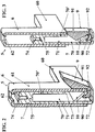
figure 3 est une vue similaire à lafigure 2 et correspondant au dispositif de limitation adoptant une configuration de déverrouillage de la butée escamotable qui adopte une position inactive ; - la
figure 4 est une vue similaire auxfigures 2 et correspondant à un détail du système de fermeture illustréet 3figure 1 et montrant le montage du dispositif de limitation sur le tablier, ceci en configuration de verrouillage de la butée escamotable en position active ; - la
figure 5 et une vue similaire à lafigure 4 et montrant le dispositif de limitation et le tablier adoptant une configuration de déverrouillage de la butée escamotable qui adopte une position inactive.
- the
figure 1 is a schematic view of a closure system of an opening that comprises a construction, this system incorporating a device for limiting the folding of the apron that includes this system; - the
figure 2 is a schematic view, in perspective and in detail of the limitation device according to the present invention, this in the locking configuration of the retractable stop in active position;
- the
figure 3 is a view similar to thefigure 2 and corresponding to the limiting device adopting an unlocking configuration of the retractable stop which adopts an inactive position; - the
figure 4 is a view similar toFigures 2 and 3 and corresponding to a detail of the illustrated closure systemfigure 1 and showing the mounting of the limiting device on the apron, this in locking configuration of the retractable stop in the active position; - the
figure 5 and a view similar to thefigure 4 and showing the limiting device and the apron adopting an unlocking configuration of the retractable stop which adopts an inactive position.
La présente invention concerne le domaine de la fabrication des systèmes 1 conçus pour assurer la fermeture d'une ouverture définie au niveau d'une construction.The present invention relates to the field of
En fait, un tel système de fermeture 1 peut être constitué par un volet roulant, une moustiquaire, un store, une porte de garage ou autre. Dans la suite de la description, il sera, plus particulièrement, fait référence à un système de fermeture 1 constitué par un volet roulant sachant que la présente invention n'est aucunement limitée à cet exemple de réalisation.In fact, such a
Quoi qu'il en soit et quel que soit ce système de fermeture 1, celui-ci comporte un tablier 2 incorporant au moins une lame, voire constitué par un assemblage (notamment de manière longitudinale) d'une pluralité de lames.Whatever the case may be, whatever the
En particulier, un tel tablier 2 comporte une lame finale 20 constituant une extrémité libre de ce tablier 2. Cette lame finale 20 comporte, d'une part, un profilé fixe 21 raccordé à une partie amont du tablier 2, d'autre part, un profilé mobile 22 constituant une extrémité distale de ce tablier 2 et, d'autre part encore, un moyen 23 pour le montage du profilé mobile 22 en déplacement par rapport au profilé fixe 21.In particular, such a
En fait, un tel moyen de montage 23 est conçu pour autoriser un coulissement de ces profilés (21 ; 22) l'un (21 ; 22) par rapport à l'autre (22 ; 21), plus particulièrement par engagement d'un tel profilé (plus particulièrement du profilé mobile 22) en partie à l'intérieur de l'autre profilé (plus particulièrement du profilé fixe 21).In fact, such a mounting means 23 is designed to allow a sliding of these sections (21; 22) one (21; 22) relative to the other (22; 21), more particularly by engagement of a such profile (more particularly the movable section 22) partly inside the other section (more particularly the fixed section 21).
Un mode préféré de réalisation de l'invention consiste en ce que ce moyen de montage 23 est de type télescopique.A preferred embodiment of the invention consists in that this mounting means 23 is of the telescopic type.
Le système de fermeture 1 comporte, également, des coulisses latérales (3 ; 3'), implantées de part et d'autre de l'ouverture, et adoptant usuellement une section en « U » ou analogue. C'est, plus particulièrement, à l'intérieur de ces coulisses latérales (3 ; 3') que sont engagées et défilent les extrémités latérales (24 ; 24') du tablier 2, plus particulièrement les extrémités latérales des lames de ce tablier 2.The
Ce système de fermeture 1 comporte, encore, un ensemble, duquel le tablier 2 est rendu solidaire, et conçu pour assurer le repliement et le déploiement de ce tablier 2.This
Un tel ensemble comporte au moins un moyen d'entraînement du tablier 2 (notamment sous la forme d'un moteur), voire encore un moyen (par exemple sous la forme d'une chaîne, d'une courroie, d'un tringle ou analogue) pour raccorder ce moyen d'entraînement audit tablier 2.Such an assembly comprises at least one driving means of the deck 2 (in particular in the form of a motor), or even a means (for example in the form of a chain, a belt, a rod or analog) for connecting this drive means to said
Cependant et selon un mode préféré de réalisation, un tel ensemble peut comporter un arbre, duquel le tablier 2 est rendu solidaire, sur lequel est replié (plus particulièrement par enroulement) et à partir duquel est déployé (plus particulièrement par déroulement) ce tablier 2.However, and according to a preferred embodiment, such an assembly may comprise a shaft, from which the
Cet ensemble comporte, alors encore, un moyen pour entraîner ledit arbre en rotation, ceci en vue d'assurer le repliement ou le déploiement du tablier 2.This assembly comprises, then again, a means for driving said shaft in rotation, in order to ensure the folding or the deployment of the
Un tel moyen d'entraînement peut être de type manuel ou, et de préférence, de type motorisé (plus particulièrement sous forme d'un moteur électrique).Such a drive means may be of the manual type or, preferably, of the motorized type (more particularly in the form of an electric motor).
Tel que visible sur les figures en annexe, le système de fermeture 1 peut, encore, comporter un caisson 4, surmontant les coulisses latérales (3 ; 3'), recevant intérieurement l'arbre d'enroulement/déroulement du tablier 2, et à l'intérieur duquel est replié ce tablier 2.As can be seen in the appended figures, the
Selon une caractéristique additionnelle, ce système de fermeture 1 comporte également un dispositif 5 de limitation du repliement du tablier 2, ceci en fin de course du repliement de ce tablier 2.According to an additional characteristic, this
Tel que visible sur les figures en annexe, ce dispositif de limitation 5 comporte un support 6 pourvu d'un moyen 60 pour la réception de la lame finale 20 du tablier 2, plus particulièrement pour la réception du profilé mobile 22 que comporte cette lame finale 20.As can be seen in the appended figures, this limiting
En fait, ce moyen 60 pour la réception de la lame finale 20 est constitué par un embout, s'étendant latéralement par rapport au support 6, et destiné à être engagé (plus particulièrement par emboîtement) et immobilisé (plus particulièrement par serrage, notamment au travers d'un emboîtement serré, ou par déformation du profilé) à l'intérieur d'un logement que comporte cette lame finale 20 (plus particulièrement que comporte le profilé mobile 22 de cette lame finale 20). A ce propos, on observera que l'embout est engagé à l'intérieur du logement de la lame finale 20, ceci latéralement par rapport à cette lame finale 20. Le support 6 équipe, alors, la lame finale 20 (et, donc, le tablier 2) et s'étend latéralement par rapport à cette lame finale 20 (et, donc, par rapport à ce tablier 2), ceci dans le plan dans lequel s'étend cette lame finale 20 (et, donc, ce tablier 2), notamment en position déployée de ce tablier 2.In fact, this means 60 for receiving the
Ce dispositif de limitation 5 comporte, encore, un élément 7 mobile par rapport au support 6. Cet élément mobile 7 comporte, d'une part, deux parois latérales et espacées (non représentées) ainsi que deux parois longitudinales parallèles (70 ; 70') et espacées, définissant entre elles (70 ; 70') un volume interne 71 à l'élément mobile 7. D'autre part, cet élément mobile 7 comporte un fond 72 , s'étendant de manière latérale (plus particulièrement de manière perpendiculaire) à partir d'une paroi longitudinale 70 et en direction de l'autre paroi longitudinale 70', et définissant avec cette autre paroi longitudinale 70' une ouverture 73.This limiting
Cet élément mobile 7 peut, encore, comporter un moyen pour la réception d'une lame finale 20 (plus particulièrement du profilé fixe 21 que comporte cette lame finale 20) que comporte le tablier 2 du système de fermeture 1. Un tel moyen de réception peut, là encore, adopter la forme d'un embout, s'étendant latéralement par rapport à cet élément mobile 7, et destiné à être engagé (plus particulièrement par emboîtement) et immobilisé (plus particulièrement par serrage, notamment au travers d'un emboîtement serré, ou par déformation du profilé) à l'intérieur d'un logement que comporte ce profilé fixe 21 de la lame finale 20.This
De manière alternative (et comme illustré
De manière additionnelle, le dispositif de limitation 5 comporte un moyen pour le montage de cet élément mobile 7 en coulissement par rapport au support 6.In addition, the limiting
Un tel moyen de montage en coulissement est constitué, d'une part, par un boîtier 61, que comporte ledit support 6, et qui reçoit, intérieurement et en coulissement, au moins une partie de l'élément mobile 7. Tel que visible sur les
D'autre part, ce moyen de montage en coulissement est constitué par un coulisseau 75, que comporte ledit élément mobile 7 (au moins en partie constitué par un tel coulisseau 75), et qui est monté en coulissement à l'intérieur du boîtier 61 du support 6, ceci entre une position escamotée à l'intérieur de ce boîtier 61 (
Tel que visible sur les figures en annexe, c'est, plus particulièrement, au niveau de ce coulisseau 75 que sont définis au moins les parois latérales, les parois longitudinales parallèles (70 ; 70'), le volume interne 71, le moyen de réception 74, voire le fond 72 et l'ouverture 73.As can be seen in the appended figures, it is, more particularly, at this
Le dispositif de limitation 5 comporte, également, une butée escamotable 9 qui peut occuper, d'une part et tel que visible
En fait, la butée escamotable 9 adopte cette position active de blocage en l'absence d'intervention (directe ou indirecte) sur le dispositif de limitation 5. En particulier, cette butée escamotable 9 occupe cette position active de blocage en fin de course de repliement du tablier 2 ainsi que dans le cadre du fonctionnement normal du tablier 2 du système de fermeture 1, plus particulièrement lors des manoeuvres de repliement/déploiement du tablier 2.In fact, the
D'autre part et tel que visible
En fait, cette butée escamotable 9 adopte cette position inactive de blocage en dehors du fonctionnement normal du tablier 2 du système de fermeture 1, plus particulièrement lorsqu'il s'agit de procéder à une intervention sur ce système 1, notamment dans le cadre du service après vente et/ou en cas de défaillance du moteur d'entraînement du tablier 2 comme il sera décrit ci-dessous.In fact, this
Selon une première caractéristique, cette butée escamotable 9 est conçue pour passer (plus particulièrement par basculement) de la position inactive de blocage vers la position active de blocage, ceci sous l'effet de la gravité et/ou sous l'effet d'un moyen de rappel (ressort ou analogue) et/ou sous l'effet d'une action (pression, répulsion) exercée par le support 6 sur cette butée escamotable 9. En fait, une telle action peut être exercée par déploiement de la lame finale 20, plus particulièrement du profilé mobile 22 de la lame finale 20, ceci après intervention sur le tablier 2 (repliement au-delà de sa position de fin de course de repliement) et lors de la remise en fonction de ce tablier 2 ou du système de fermeture 1. Une telle action est, plus particulièrement, exercée sous l'effet d'une traction descendante exercée sur le support 6, plus particulièrement par l'intermédiaire du profilé mobile 22 de la lame finale 20 (notamment sous l'effet d'une traction descendante exercée sur ce profilé mobile 22).According to a first feature, this
Tel que visible sur les figures en annexe, la butée escamotable 9 adopte la forme d'un cavalier comportant une branche interne 90, une branche externe 91, ainsi qu'un organe de raccordement 92 de ces deux branches (interne 90 ; externe 91).As can be seen in the appended figures, the
Selon une autre caractéristique, au moins la branche externe 91 (voire encore la branche interne 90) s'étend à partir de l'organe de raccordement 92 en divergeant.According to another feature, at least the outer branch 91 (or even the inner branch 90) extends from the connecting
La branche externe 91 présente une longueur supérieure à la branche interne 90, plus particulièrement pour autoriser le basculement de cette butée escamotable 9 de la position inactive vers la position active, ceci sous l'effet de la gravité.The
De plus, cette branche externe 91 comporte au moins une extrémité libre (voire encore un prolongement de cette extrémité libre en direction de l'organe de raccordement 92) conformée en biseau pour faciliter une prise d'appui sur un moyen d'appui pour interrompre le repliement du tablier 2 et/ou pour permettre au support 6 de glisser par rapport à la butée escamotable 9 en vue de repousser celle-ci 9 en direction de sa position active.In addition, this
On observera que l'organe de raccordement 92 comporte une portion plane, qui présente une arête commune avec la branche interne 90, et qui est conçue pour reposer sur le fond 72 de l'élément mobile 7, ceci en position active de la butée escamotable 9.It will be observed that the connecting
Tel que visible sur les figures en annexe, c'est, plus particulièrement, l'élément mobile 7 qui comporte une telle butée escamotable 9.As can be seen in the appended figures, it is, more particularly, the
Ainsi et au moins en position active de blocage de la butée escamotable 9 (
Selon une autre caractéristique, le dispositif de limitation 5 comporte, encore, un moyen pour le montage de la butée escamotable 9 en déplacement par rapport à l'élément mobile 7, ceci entre la position active de blocage et la position inactive de blocage de cette butée escamotable 9.According to another characteristic, the
Selon l'invention, ce moyen pour le montage de la butée escamotable 9 en déplacement par rapport à l'élément mobile 7 est constitué par un moyen de montage en rotation de cette butée escamotable 9 par rapport à cet élément mobile 7.According to the invention, this means for mounting the
En fait, ce moyen de montage en rotation est conçu pour permettre une rotation de la butée escamotable 9 autour d'un axe perpendiculaire à la direction de coulissement de l'élément mobile 7 par rapport au support 6. Cet axe est, alors, également parallèle aux parois longitudinales (70 ; 70') et perpendiculaire aux parois latérales de cet élément mobile 7.In fact, this rotational mounting means is designed to allow rotation of the
On observera que ce moyen de montage en rotation est conçu pour autoriser une rotation libre selon un angle compris entre 20 et 40°, de préférence de l'ordre de 30° environ.It will be observed that this rotational mounting means is designed to allow free rotation at an angle of between 20 and 40 °, preferably of the order of 30 °.
Selon un mode préféré de réalisation de l'invention, le moyen de montage en rotation de la butée escamotable 9 par rapport à l'élément mobile 7 est constitué par des moyens pour clipper la butée escamotable 9 entre les parois latérales parallèles de l'élément mobile 7.According to a preferred embodiment of the invention, the rotational mounting means of the
En fait, les moyens pour clipper comportent des tétons équipant latéralement la butée escamotable 9 (ou respectivement les parois latérales), ainsi que des logements, conçus pour coopérer avec les tétons, et définis en correspondance dans les parois latérales (respectivement dans la butée escamotable 9).In fact, the means for clipping comprise nipples equipping laterally the retractable stop 9 (or respectively the side walls), as well as housings, designed to cooperate with the nipples, and defined in correspondence in the side walls (respectively in the retractable stop 9).
Encore une autre caractéristique de l'invention consiste en ce que le dispositif 5 de limitation du repliement comporte au moins un moyen 10 pour limiter le déplacement, au moins en rotation et/ou en translation, de la butée escamotable 9 par rapport à l'élément mobile 7.Yet another feature of the invention consists in that the
Tel que visible sur les figures en annexe, le moyen 10 pour limiter le déplacement en rotation de la butée escamotable 9 par rapport à l'élément mobile 7 comporte au moins un doigt équipant une paroi longitudinale 70 de l'élément mobile 7, s'étendant à partir de cette paroi longitudinale 70 et en direction de la butée escamotable 9, et contre lequel vient prendre appui cette butée escamotable 9.As can be seen in the appended figures, the
En fait, c'est, plus particulièrement, contre ce doigt que vient prendre appui, soit la branche interne 90 de la butée escamotable 9 en position active de blocage (
En ce qui concerne le moyen pour limiter le déplacement en translation, celui-ci peut être constitué, d'une part, par au moins une languette équipant l'organe de raccordement 92 et s'étendant à partir de cet organe de raccordement 92 et en direction du fond 72 de l'élément mobile 7 et, d'autre part, par au moins un logement que comporte le fond 72 de l'élément mobile 7 et ménagé en correspondant d'une telle languette.With regard to the means for limiting the movement in translation, this can be constituted, on the one hand, by at least one tongue equipping the connecting
Finalement, le dispositif de limitation 5 comporte un moyen pour le verrouillage de la butée escamotable 9 en position active de blocage.Finally, the limiting
A ce propos, on observera que le moyen pour le verrouillage de la butée escamotable 9 en position active de blocage est conçu pour assurer un tel verrouillage, ceci sous l'effet de la gravité et/ou sous l'effet d'un moyen de rappel (ressort ou analogue) et/ou sous l'effet d'une traction descendante exercée sur le support 6, plus particulièrement par l'intermédiaire du profilé mobile 22 que comporte la lame finale 20 (notamment sous l'effet d'une traction descendante exercée sur ce profilé mobile 22).In this regard, it will be observed that the means for locking the
Ce moyen de verrouillage permet, avantageusement, d'assurer un verrouillage de la butée escamotable 9 en position active de blocage, ceci au moins pendant la manoeuvre de repliement du tablier 2 (en particulier en fin de course de repliement du tablier 2), voire pendant toutes les manoeuvres de repliement/déploiement de ce tablier 2.This locking means advantageously makes it possible to lock the
En fait, ce moyen de verrouillage de la butée escamotable 9 est constitué par le support 6 qui, par coulissement de l'élément mobile 7 par rapport au support 6 (ou par coulissement du support 6 par rapport à l'élément mobile 7), peut occuper, d'une part, une position de verrouillage de la butée escamotable 9 en position active de blocage (
C'est, plus particulièrement, dans cette position de déverrouillage que cette butée escamotable 9 est libre en déplacement (en rotation) par rapport à l'élément mobile 7 et est susceptible d'être amenée dans une position inactive de blocage (
A ce propos, on observera que ce moyen de verrouillage (plus particulièrement le support 6) est conçu pour permettre un tel déverrouillage, ceci sous l'effet d'une pression exercée vers le haut et sur le support 6, plus particulièrement par l'intermédiaire du profilé mobile 22 que comporte la lame finale 20 (notamment sous l'effet d'une pression vers le haut exercée sur ce profilé mobile 22).In this regard, it will be observed that this locking means (more particularly the support 6) is designed to allow such an unlocking, this under the effect of a pressure exerted upwards and on the
L'invention concerne, alors, un dispositif 5, présentant les caractéristiques décrites ci-dessus, et conçu pour assurer la limitation du repliement du tablier 2 d'un système de fermeture 1, ceci en fin de course du repliement de ce tablier 2.The invention relates, then, to a
Cette invention concerne, également, un tablier 2 de système de fermeture 1, plus particulièrement de type volet roulant, moustiquaire, store, porte de garage.This invention also relates to an
Tel que mentionné ci-dessus, ce tablier 2 comporte une lame finale 20 comportant un profilé fixe 21, un profilé mobile 22, et un moyen 23 pour le montage du profilé mobile 22 en déplacement (coulissement) par rapport au profilé fixe 21.As mentioned above, this
Ce tablier 2 comporte, alors, également, un dispositif de limitation 5 du repliement de ce tablier 2 présentant les caractéristiques décrites ci-dessus.This
En particulier, ce dispositif de limitation 5 comporte un support 6 pourvu d'un moyen 60 pour la réception de la lame finale 20 (plus particulièrement du profilé mobile 22 de cette lame finale 20) du tablier 2.In particular, this limiting
Dans un pareil cas et tel que décrit ci-dessus, le moyen 60 pour la réception de la lame finale 20 est constitué par un embout (s'étendant latéralement par rapport au support 6, plus particulièrement par rapport au boîtier 61 de ce support 6) tandis que cette lame finale 20 (plus particulièrement son profilé mobile 22) comporte un logement à l'intérieur duquel ledit embout est engagé et immobilisé.In such a case and as described above, the
En ce qui concerne l'élément mobile 7, que comporte ce dispositif 5 de limitation du repliement du tablier 2, celui-ci 7 est pourvu d'un moyen 74 pour la réception, soit de la lame finale 20 (plus particulièrement du profilé fixe 21 de cette lame finale 20) du tablier 2, soit d'une pièce 8 (plus particulièrement sous forme d'un feuillard illustré
En ce qui concerne le moyen 23 pour le montage du profilé mobile 22 en déplacement par rapport au profilé fixe 21, celui-ci 23 est conçu pour autoriser un coulissement de ces profilés (21 ; 22) l'un (21 ; 22) par rapport à l'autre (22 ; 21).Regarding the
Ce moyen 23 de montage est constitué par un moyen de montage de type en coulissement et/ou télescopique.This mounting means 23 is constituted by a sliding type mounting means and / or telescopic.
Finalement, la présente invention concerne un système de fermeture 1 destiné à équiper une ouverture définie au niveau d'une construction. Un tel système de fermeture 1 peut être constitué par un volet roulant, une moustiquaire, un store, une porte de garage ou autre.Finally, the present invention relates to a
Ce système de fermeture 1 comporte :
un tablier 2 ;- des coulisses latérales (3 ; 3') à l'intérieur desquelles se déplacent les extrémités latérales (24 ; 24') du
tablier 2 ; - au moins un caisson à l'intérieur duquel est enroulé et à partir duquel est déroulé le tablier 2 ;
un dispositif 5 de limitation du repliement du tablier 5 en fin de course de repliement du tablier 2.
- an
apron 2; - lateral slides (3; 3 ') within which the lateral ends (24; 24') of the
apron 2 move; - at least one box inside which is wound and from which the
apron 2 is unwound; - a
device 5 for limiting the folding of theapron 5 at the end of the folding stroke of theapron 2.
Selon l'invention, le tablier 2 présente les caractéristiques décrites ci-dessus. En particulier, ce tablier 2 comporte le dispositif 5 de limitation présentant les caractéristiques mentionnées ci-dessus.According to the invention, the
De plus, l'une au moins des coulisses (3 ; 3') et/ou le caisson comportent au moins un moyen d'appui conçu pour coopérer avec la butée escamotable 9 en position active de blocage, ceci pour interrompre le repliement du tablier 2 en fin de course de repliement de ce tablier 2.In addition, at least one of the slides (3; 3 ') and / or the box comprise at least one support means designed to cooperate with the
Une autre caractéristique consiste en ce qu'au moins une partie du dispositif de limitation 5 (plus particulièrement au moins le support 6, l'élément mobile 7 et la butée escamotable 9 que comporte ce dispositif 5) est positionnée et se déplace à l'intérieur d'une coulisse latérale (3 ; 3').Another feature is that at least a part of the limitation device 5 (more particularly at least the
Cette invention trouvera une utilité toute particulière lorsqu'il s'agit d'intervenir sur un tel système de fermeture 1 en cas de panne du moyen d'entraînement (plus particulièrement motorisé) de l'arbre d'enroulement/déroulement du tablier 2, plus particulièrement lorsque ce tablier 2 est en position de fin de course de repliement.This invention will find a particular use when it comes to intervene on such a
Dans un pareil cas, un opérateur exerce une action sur le profilé mobile 22 de la lame finale 20 consistant à repousser, par coulissement, ce profilé mobile 22 en direction et à l'intérieur du profilé fixe 21 de cette lame finale 20.In such a case, an operator exerts an action on the
Cette action est constituée par une pression exercée vers le haut et sur le profilé mobile 22.This action is constituted by a pressure exerted upwards and on the
Par cette action, le profilé mobile 22 entraîne le support 6 du dispositif de limitation 5 en coulissement par rapport à l'élément mobile 7. Ce support 7 passe, alors, de la position de verrouillage de la butée escamotable 9 (
Ensuite, l'opérateur provoque un basculement de la butée escamotable 9 (déverrouillée) de sa position active de blocage vers sa position inactive de blocage, ceci notamment en introduisant un outil (par exemple un tournevis) à l'intérieur d'une coulisse latérale. Ceci provoque, alors, l'interruption de la coopération entre la butée escamotable 9 et le moyen d'appui, ce qui libère le tablier 2 dont le repliement n'est plus limité.Then, the operator causes a tilting of the retractable stop 9 (unlocked) from its active locking position to its inactive blocking position, this in particular by introducing a tool (for example a screwdriver) inside a lateral slide . This causes, then, the interruption of the cooperation between the
Il devient, alors, possible de repousser le tablier 2 au-delà de sa position de fin de course, plus particulièrement à l'intérieur du caisson. Ceci permet, ainsi, à l'opérateur de démonter facilement le tablier 2 et d'accéder à l'organe défectueux en vue de sa réparation ou de son remplacement.It becomes, then, possible to push the
Après intervention sur l'organe défectueux, l'opérateur exerce une traction sur le tablier 2 (notamment sur la lame finale 20, plus particulièrement sur le profilé mobile 22) et/ou actionne le moyen d'entraînement de ce tablier 2. Le positionnement de la butée escamotable 9 dans sa position active de blocage et le verrouillage de cette butée escamotable 9 dans sa position active de blocage se font de manière automatique (plus particulièrement par gravité et/ou par action sur la lame finale 20, notamment sur le profilé mobile 22 de cette lame finale 20 comme décrit ci-dessus) lors de l'entrée de la lame finale 20 dans la coulisse latérale (3 ; 3').After intervention on the defective member, the operator exerts traction on the deck 2 (in particular on the
Claims (14)
- A closing system (1) such as a roller blind, mosquito net, blind, garage door or the like, for equipping an opening defined at the level of a building, this system comprising:- an apron (2) including an end slat (20);- side guides (3; 3') inside which move the side ends of the apron (2) and/or at least one box (4) inside which is wound and from which unwinds the apron (2);- a device (5) for limiting the folding of the apron (2) at the end of the travel distance for folding of the apron (2), this device (5) including;- a support (6) provided with means (60) for receiving the end slat (20) of the apron (2);- an element movable (7) relative to this support (6);- a retractable stop (9), which, at the end of the travel distance for folding of the apron (2), can occupy, on the one hand and in the absence of an intervention on the limiting device (5), an active blocking position in which this stop (9) cooperates with a supporting means the opening and/or at least one of the slides (3; 3') and/or the box (4) of the closing system (1) include, for interrupting the folding of the apron (2) and, on the other hand and under the action of an intervention on the limiting device (5), an inactive blocking position in which this stop (9) is retracted relative to this supporting means, for allowing the continuation of the folding of the apron (2) beyond the end limit position;- means for locking the retractable stop (9) in the active locking position;- means for mounting the movable element (7) slidably relative to the support (6) as well as means for mounting the retractable stop (9) movable relative to the movable element (7), between the active locking position and the inactive locking position;- wherein the movable element (7) includes the retractable stop (9), while the means for locking the retractable stop (9) is formed by the support (6) which, through sliding of the movable element (7) relative to the support (6), can occupy, on the one hand, a locking position of the retractable stop (9) in the active blocking position and, on the other hand, an unlocking position of the retractable stop (9).
- The closing system (1) according to claim 1, wherein the support (6) includes a casing (61) receiving, internally and slidably, a slide (75) the movable element (7) includes, and which is mounted slidably between a retracted position inside this casing (61) and a position extended outside the casing (61).
- The closing system (1) according to any one of the preceding claims, wherein the support (6) is provided with means (60) for receiving a final slat (20) the apron (2) of the closing system (1) includes, while the movable element (7) is provided with means (74) for receiving either a final slat (20) the apron (2) of the closing system (1) includes, or a part (8) for controlling the orientation of guidable slats the apron (2) of the closing system (1) includes.
- The closing system (1) according to any one of the preceding claims, wherein the movable element (7) includes two parallel and spaced apart side walls, two parallel and spaced apart longitudinal walls (70; 70') as well as a bottom (72) extending laterally from such a longitudinal wall (70) and defining with the other longitudinal wall (70') an opening (73) through which passes the retractable stop (9).
- The closing system (1) according to any one of the preceding claims, wherein the means for mounting the retractable stop (9) movably relative to the movable element (7) is formed by means for mounting the retractable stop (9) rotationally relative to the movable element (7), more particularly designed so as to permit a rotation of the retractable stop (9) about an axis perpendicular to the sliding direction of the movable element (7) relative to the support (6).
- The closing system (1) according to claims 4 and 5, wherein the means for mounting the retractable stop (9) rotationally relative to the movable element (7) is formed by means for fixing the retractable stop (9) between the parallel side walls of the movable element (7).
- The closing system (1) according to any one of the preceding claims, wherein it includes at least one means (10) for limiting the movement, at least in rotation and/or in translation, of the retractable stop (9) relative to the movable element (7).
- The closing system (1) according to claims 4 and 7, wherein the means (10) for limiting the rotational movement of the retractable stop (9) relative to the movable element (7) includes at least one finger equipping a longitudinal wall (70) of the movable element (7) extending from this longitudinal wall (70) and towards the retractable stop (9), and against which rests the retractable stop (9).
- The closing system (1) according to any one of the preceding claims, wherein the retractable stop (9) is designed so as to pass from the inactive position to the active position, under the action of gravity and/or under the impulse of an action exerted by the support (6) onto this retractable stop (9).
- The closing system (1) according to any one of the preceding claims, wherein the retractable stop (9) adopts the shape of a rider including an inner leg (90) extending inside the movable element (6), an outer leg (91) extending outside the movable element (7) as well as an organ (92) connecting the two legs (90 ; 91).
- The closing system (1) according to claim 10, wherein the outer leg (91) extends from the connecting organ (92) while diverging and/or has a length larger than the inner leg (90) and/or has at least one beveled free end in order to facilitate the resting on a supporting means for interrupting the folding of the apron (2) and/or for permitting the support (6) to slide relative to the retractable stop (9) in order to push the latter towards its active position.
- The closing system (1) according to any one of the preceding claims, wherein the final slat (20) of the apron (2) includes a fixed profile (21), a movable profile (22), as well as means (23) for mounting the movable section (22) movably relative to the fixed profile (21).
- The closing system (1) according to any one of the preceding claims, wherein the means (60) for receiving the final slat (20) is formed by a ferrule, while the final blade (20) includes a recess within which said ferrule is inserted and immobilized.
- The closing system (1) according to any one of the preceding claims, wherein the movable element (7) is provided with means (74) for receiving either the end slat (20) of the apron (2) or a part (8) for controlling the orientation of the guidable slats this apron (2) includes.
Applications Claiming Priority (1)
| Application Number | Priority Date | Filing Date | Title |
|---|---|---|---|
| FR1154586A FR2975725B1 (en) | 2011-05-26 | 2011-05-26 | DEVICE FOR LIMITING THE FOLDING OF THE APRON OF AN OCCULTATION SYSTEM, APRON COMPRISING SUCH A LIMITATION DEVICE AND OCCULTATION SYSTEM COMPRISING SUCH AN APRON |
Publications (2)
| Publication Number | Publication Date |
|---|---|
| EP2527583A1 EP2527583A1 (en) | 2012-11-28 |
| EP2527583B1 true EP2527583B1 (en) | 2016-03-30 |
Family
ID=46177380
Family Applications (1)
| Application Number | Title | Priority Date | Filing Date |
|---|---|---|---|
| EP12305578.2A Active EP2527583B1 (en) | 2011-05-26 | 2012-05-24 | Concealment system comprising an apron which comprises a device for limiting the folding of the apron |
Country Status (4)
| Country | Link |
|---|---|
| EP (1) | EP2527583B1 (en) |
| ES (1) | ES2570165T3 (en) |
| FR (1) | FR2975725B1 (en) |
| PL (1) | PL2527583T3 (en) |
Family Cites Families (3)
| Publication number | Priority date | Publication date | Assignee | Title |
|---|---|---|---|---|
| DE3214092A1 (en) * | 1982-04-16 | 1983-10-20 | Alukon F. Grashei Kg, 8671 Konradsreuth | DEVICE FOR LIMITING THE REWINDING MOVEMENT OF A ROLLER SHUTTER TANK OR THE LIKE |
| ES293673Y (en) * | 1986-04-18 | 1987-05-16 | Estevez Miro Jaime | LOCKING DEVICE FOR BLINDS AND THE LIKE |
| FR2918699A1 (en) * | 2007-07-09 | 2009-01-16 | Midi Moulages Plast | ROLLING SHUTTER COMPRISING A STOP DEVICE FOR LIMITING THE WINDING OF THE APRON IN THE BOX. |
-
2011
- 2011-05-26 FR FR1154586A patent/FR2975725B1/en not_active Expired - Fee Related
-
2012
- 2012-05-24 ES ES12305578T patent/ES2570165T3/en active Active
- 2012-05-24 EP EP12305578.2A patent/EP2527583B1/en active Active
- 2012-05-24 PL PL12305578.2T patent/PL2527583T3/en unknown
Also Published As
| Publication number | Publication date |
|---|---|
| EP2527583A1 (en) | 2012-11-28 |
| FR2975725A1 (en) | 2012-11-30 |
| PL2527583T3 (en) | 2016-09-30 |
| FR2975725B1 (en) | 2013-06-21 |
| ES2570165T3 (en) | 2016-05-17 |
Similar Documents
| Publication | Publication Date | Title |
|---|---|---|
| EP2112321B1 (en) | Roller blind equipped with a brake | |
| EP1975367A1 (en) | Device for protecting an opening of a construction | |
| EP2527583B1 (en) | Concealment system comprising an apron which comprises a device for limiting the folding of the apron | |
| EP1593809B1 (en) | Locking device for a slat of a roller shutter and slat having such a blocking device | |
| EP3263826B1 (en) | Roller shutter with adjustable slats | |
| EP2454439B1 (en) | Device for controlling the projection of an apron of roller blind, and roller blind provided with such a device | |
| EP1672163B1 (en) | Device to prevent disengagement of a shutter lamella from a side rail | |
| EP2783063B1 (en) | Roller shutter equipped with an operation device for the projection of an apron of a shutter | |
| EP2037078B1 (en) | Self-blocking device for a roller shutter apron | |
| EP2942472B1 (en) | Closure device such as a blind, roller blind or the like, in particular for a skylight | |
| FR2883027A1 (en) | Limit stop device for apron of roller shutter, has locking plate equipped with lateral end of end slate of apron to extend from lower edge to upper edge of slate, where plate has end folded towards slate to form stop relative to stop unit | |
| EP2690245B1 (en) | Funnel and guide rail for a rolling shutter | |
| EP2085565B1 (en) | Device preventing the lifting of a covering element of a closure device, such as a roller shutter, blind, mosquito net or similar. | |
| EP1927718B1 (en) | Device limiting the opening of a screen and closing or sun-protection installation including such a device | |
| EP2037077B1 (en) | Guide rail for a concealing device | |
| EP1997999B1 (en) | Tab for attaching a support panel to a lateral sliding guide of a deployable structure | |
| EP0690200B1 (en) | Locking device for roller shutter | |
| EP2196617B1 (en) | Anti-lift system for a closure device of the roller shutter type | |
| FR2808556A1 (en) | Guide for roller shutter has U-shaped blade on blind panel lateral slide to co-operate with sleeve on end louvre | |
| EP2907947B1 (en) | Locking device for semi-fixed door or window leaf | |
| EP3623564B1 (en) | Closing or concealing device with apron and break-in prevention system | |
| FR2982305A1 (en) | Lock for locking door leaf of e.g. door window, has thrust unit arranged on trajectory of control unit that is movable with respect to door leaf, and control unit movably arranged to move when door leaf is locked by user | |
| FR3075847A1 (en) | LOCK AND TRAPPER COMPRISING SUCH A LATCH | |
| FR2920467A1 (en) | Apron's end stop device for roller shutter of e.g. warehouse, has stop element positioned in support element for introducing stop unit in chamber of lateral end of final slat such that rod is parallel to longitudinal axis of slat | |
| EP2549052B1 (en) | Device for tensioning a means for controlling the position of at least one mobile slat of a lattice of a concealment device |
Legal Events
| Date | Code | Title | Description |
|---|---|---|---|
| PUAI | Public reference made under article 153(3) epc to a published international application that has entered the european phase |
Free format text: ORIGINAL CODE: 0009012 |
|
| AK | Designated contracting states |
Kind code of ref document: A1 Designated state(s): AL AT BE BG CH CY CZ DE DK EE ES FI FR GB GR HR HU IE IS IT LI LT LU LV MC MK MT NL NO PL PT RO RS SE SI SK SM TR |
|
| AX | Request for extension of the european patent |
Extension state: BA ME |
|
| 17P | Request for examination filed |
Effective date: 20130514 |
|
| GRAP | Despatch of communication of intention to grant a patent |
Free format text: ORIGINAL CODE: EPIDOSNIGR1 |
|
| INTG | Intention to grant announced |
Effective date: 20151201 |
|
| GRAS | Grant fee paid |
Free format text: ORIGINAL CODE: EPIDOSNIGR3 |
|
| GRAA | (expected) grant |
Free format text: ORIGINAL CODE: 0009210 |
|
| AK | Designated contracting states |
Kind code of ref document: B1 Designated state(s): AL AT BE BG CH CY CZ DE DK EE ES FI FR GB GR HR HU IE IS IT LI LT LU LV MC MK MT NL NO PL PT RO RS SE SI SK SM TR |
|
| REG | Reference to a national code |
Ref country code: GB Ref legal event code: FG4D Free format text: NOT ENGLISH |
|
| REG | Reference to a national code |
Ref country code: CH Ref legal event code: EP |
|
| REG | Reference to a national code |
Ref country code: AT Ref legal event code: REF Ref document number: 785623 Country of ref document: AT Kind code of ref document: T Effective date: 20160415 |
|
| REG | Reference to a national code |
Ref country code: IE Ref legal event code: FG4D Free format text: LANGUAGE OF EP DOCUMENT: FRENCH |
|
| REG | Reference to a national code |
Ref country code: DE Ref legal event code: R096 Ref document number: 602012016236 Country of ref document: DE |
|
| REG | Reference to a national code |
Ref country code: ES Ref legal event code: FG2A Ref document number: 2570165 Country of ref document: ES Kind code of ref document: T3 Effective date: 20160517 |
|
| REG | Reference to a national code |
Ref country code: FR Ref legal event code: PLFP Year of fee payment: 5 |
|
| REG | Reference to a national code |
Ref country code: LT Ref legal event code: MG4D |
|
| PG25 | Lapsed in a contracting state [announced via postgrant information from national office to epo] |
Ref country code: HR Free format text: LAPSE BECAUSE OF FAILURE TO SUBMIT A TRANSLATION OF THE DESCRIPTION OR TO PAY THE FEE WITHIN THE PRESCRIBED TIME-LIMIT Effective date: 20160330 Ref country code: GR Free format text: LAPSE BECAUSE OF FAILURE TO SUBMIT A TRANSLATION OF THE DESCRIPTION OR TO PAY THE FEE WITHIN THE PRESCRIBED TIME-LIMIT Effective date: 20160701 Ref country code: FI Free format text: LAPSE BECAUSE OF FAILURE TO SUBMIT A TRANSLATION OF THE DESCRIPTION OR TO PAY THE FEE WITHIN THE PRESCRIBED TIME-LIMIT Effective date: 20160330 Ref country code: NO Free format text: LAPSE BECAUSE OF FAILURE TO SUBMIT A TRANSLATION OF THE DESCRIPTION OR TO PAY THE FEE WITHIN THE PRESCRIBED TIME-LIMIT Effective date: 20160630 |
|
| REG | Reference to a national code |
Ref country code: NL Ref legal event code: MP Effective date: 20160330 |
|
| REG | Reference to a national code |
Ref country code: AT Ref legal event code: MK05 Ref document number: 785623 Country of ref document: AT Kind code of ref document: T Effective date: 20160330 |
|
| PG25 | Lapsed in a contracting state [announced via postgrant information from national office to epo] |
Ref country code: LV Free format text: LAPSE BECAUSE OF FAILURE TO SUBMIT A TRANSLATION OF THE DESCRIPTION OR TO PAY THE FEE WITHIN THE PRESCRIBED TIME-LIMIT Effective date: 20160330 Ref country code: LT Free format text: LAPSE BECAUSE OF FAILURE TO SUBMIT A TRANSLATION OF THE DESCRIPTION OR TO PAY THE FEE WITHIN THE PRESCRIBED TIME-LIMIT Effective date: 20160330 Ref country code: RS Free format text: LAPSE BECAUSE OF FAILURE TO SUBMIT A TRANSLATION OF THE DESCRIPTION OR TO PAY THE FEE WITHIN THE PRESCRIBED TIME-LIMIT Effective date: 20160330 Ref country code: SE Free format text: LAPSE BECAUSE OF FAILURE TO SUBMIT A TRANSLATION OF THE DESCRIPTION OR TO PAY THE FEE WITHIN THE PRESCRIBED TIME-LIMIT Effective date: 20160330 Ref country code: BE Free format text: LAPSE BECAUSE OF NON-PAYMENT OF DUE FEES Effective date: 20160531 |
|
| PG25 | Lapsed in a contracting state [announced via postgrant information from national office to epo] |
Ref country code: NL Free format text: LAPSE BECAUSE OF FAILURE TO SUBMIT A TRANSLATION OF THE DESCRIPTION OR TO PAY THE FEE WITHIN THE PRESCRIBED TIME-LIMIT Effective date: 20160330 |
|
| PG25 | Lapsed in a contracting state [announced via postgrant information from national office to epo] |
Ref country code: IS Free format text: LAPSE BECAUSE OF FAILURE TO SUBMIT A TRANSLATION OF THE DESCRIPTION OR TO PAY THE FEE WITHIN THE PRESCRIBED TIME-LIMIT Effective date: 20160730 Ref country code: EE Free format text: LAPSE BECAUSE OF FAILURE TO SUBMIT A TRANSLATION OF THE DESCRIPTION OR TO PAY THE FEE WITHIN THE PRESCRIBED TIME-LIMIT Effective date: 20160330 |
|
| PG25 | Lapsed in a contracting state [announced via postgrant information from national office to epo] |
Ref country code: PT Free format text: LAPSE BECAUSE OF FAILURE TO SUBMIT A TRANSLATION OF THE DESCRIPTION OR TO PAY THE FEE WITHIN THE PRESCRIBED TIME-LIMIT Effective date: 20160801 Ref country code: AT Free format text: LAPSE BECAUSE OF FAILURE TO SUBMIT A TRANSLATION OF THE DESCRIPTION OR TO PAY THE FEE WITHIN THE PRESCRIBED TIME-LIMIT Effective date: 20160330 Ref country code: CZ Free format text: LAPSE BECAUSE OF FAILURE TO SUBMIT A TRANSLATION OF THE DESCRIPTION OR TO PAY THE FEE WITHIN THE PRESCRIBED TIME-LIMIT Effective date: 20160330 Ref country code: RO Free format text: LAPSE BECAUSE OF FAILURE TO SUBMIT A TRANSLATION OF THE DESCRIPTION OR TO PAY THE FEE WITHIN THE PRESCRIBED TIME-LIMIT Effective date: 20160330 Ref country code: SM Free format text: LAPSE BECAUSE OF FAILURE TO SUBMIT A TRANSLATION OF THE DESCRIPTION OR TO PAY THE FEE WITHIN THE PRESCRIBED TIME-LIMIT Effective date: 20160330 Ref country code: SK Free format text: LAPSE BECAUSE OF FAILURE TO SUBMIT A TRANSLATION OF THE DESCRIPTION OR TO PAY THE FEE WITHIN THE PRESCRIBED TIME-LIMIT Effective date: 20160330 |
|
| PG25 | Lapsed in a contracting state [announced via postgrant information from national office to epo] |
Ref country code: LU Free format text: LAPSE BECAUSE OF FAILURE TO SUBMIT A TRANSLATION OF THE DESCRIPTION OR TO PAY THE FEE WITHIN THE PRESCRIBED TIME-LIMIT Effective date: 20160524 |
|
| REG | Reference to a national code |
Ref country code: CH Ref legal event code: PL |
|
| REG | Reference to a national code |
Ref country code: DE Ref legal event code: R097 Ref document number: 602012016236 Country of ref document: DE |
|
| PG25 | Lapsed in a contracting state [announced via postgrant information from national office to epo] |
Ref country code: CH Free format text: LAPSE BECAUSE OF NON-PAYMENT OF DUE FEES Effective date: 20160531 Ref country code: DK Free format text: LAPSE BECAUSE OF FAILURE TO SUBMIT A TRANSLATION OF THE DESCRIPTION OR TO PAY THE FEE WITHIN THE PRESCRIBED TIME-LIMIT Effective date: 20160330 Ref country code: LI Free format text: LAPSE BECAUSE OF NON-PAYMENT OF DUE FEES Effective date: 20160531 |
|
| PLBE | No opposition filed within time limit |
Free format text: ORIGINAL CODE: 0009261 |
|
| STAA | Information on the status of an ep patent application or granted ep patent |
Free format text: STATUS: NO OPPOSITION FILED WITHIN TIME LIMIT |
|
| REG | Reference to a national code |
Ref country code: IE Ref legal event code: MM4A |
|
| GBPC | Gb: european patent ceased through non-payment of renewal fee |
Effective date: 20160630 |
|
| 26N | No opposition filed |
Effective date: 20170103 |
|
| REG | Reference to a national code |
Ref country code: FR Ref legal event code: PLFP Year of fee payment: 6 |
|
| PG25 | Lapsed in a contracting state [announced via postgrant information from national office to epo] |
Ref country code: SI Free format text: LAPSE BECAUSE OF FAILURE TO SUBMIT A TRANSLATION OF THE DESCRIPTION OR TO PAY THE FEE WITHIN THE PRESCRIBED TIME-LIMIT Effective date: 20160330 Ref country code: GB Free format text: LAPSE BECAUSE OF NON-PAYMENT OF DUE FEES Effective date: 20160630 Ref country code: IE Free format text: LAPSE BECAUSE OF NON-PAYMENT OF DUE FEES Effective date: 20160524 |
|
| REG | Reference to a national code |
Ref country code: FR Ref legal event code: PLFP Year of fee payment: 7 |
|
| PG25 | Lapsed in a contracting state [announced via postgrant information from national office to epo] |
Ref country code: CY Free format text: LAPSE BECAUSE OF FAILURE TO SUBMIT A TRANSLATION OF THE DESCRIPTION OR TO PAY THE FEE WITHIN THE PRESCRIBED TIME-LIMIT Effective date: 20160330 Ref country code: HU Free format text: LAPSE BECAUSE OF FAILURE TO SUBMIT A TRANSLATION OF THE DESCRIPTION OR TO PAY THE FEE WITHIN THE PRESCRIBED TIME-LIMIT; INVALID AB INITIO Effective date: 20120524 |
|
| PG25 | Lapsed in a contracting state [announced via postgrant information from national office to epo] |
Ref country code: TR Free format text: LAPSE BECAUSE OF FAILURE TO SUBMIT A TRANSLATION OF THE DESCRIPTION OR TO PAY THE FEE WITHIN THE PRESCRIBED TIME-LIMIT Effective date: 20160330 Ref country code: MK Free format text: LAPSE BECAUSE OF FAILURE TO SUBMIT A TRANSLATION OF THE DESCRIPTION OR TO PAY THE FEE WITHIN THE PRESCRIBED TIME-LIMIT Effective date: 20160330 Ref country code: MT Free format text: LAPSE BECAUSE OF FAILURE TO SUBMIT A TRANSLATION OF THE DESCRIPTION OR TO PAY THE FEE WITHIN THE PRESCRIBED TIME-LIMIT Effective date: 20160330 Ref country code: MC Free format text: LAPSE BECAUSE OF FAILURE TO SUBMIT A TRANSLATION OF THE DESCRIPTION OR TO PAY THE FEE WITHIN THE PRESCRIBED TIME-LIMIT Effective date: 20160330 |
|
| PG25 | Lapsed in a contracting state [announced via postgrant information from national office to epo] |
Ref country code: BG Free format text: LAPSE BECAUSE OF FAILURE TO SUBMIT A TRANSLATION OF THE DESCRIPTION OR TO PAY THE FEE WITHIN THE PRESCRIBED TIME-LIMIT Effective date: 20160330 |
|
| PG25 | Lapsed in a contracting state [announced via postgrant information from national office to epo] |
Ref country code: AL Free format text: LAPSE BECAUSE OF FAILURE TO SUBMIT A TRANSLATION OF THE DESCRIPTION OR TO PAY THE FEE WITHIN THE PRESCRIBED TIME-LIMIT Effective date: 20160330 |
|
| PGFP | Annual fee paid to national office [announced via postgrant information from national office to epo] |
Ref country code: DE Payment date: 20240627 Year of fee payment: 13 |
|
| PGFP | Annual fee paid to national office [announced via postgrant information from national office to epo] |
Ref country code: ES Payment date: 20240627 Year of fee payment: 13 |
|
| PGFP | Annual fee paid to national office [announced via postgrant information from national office to epo] |
Ref country code: IT Payment date: 20240528 Year of fee payment: 13 Ref country code: FR Payment date: 20240521 Year of fee payment: 13 |
|
| PGFP | Annual fee paid to national office [announced via postgrant information from national office to epo] |
Ref country code: PL Payment date: 20240426 Year of fee payment: 13 |