EP2525533B1 - Procédé et appareil pour fournir une communication bidirectionnelle entre segments d'un réseau domestique - Google Patents
Procédé et appareil pour fournir une communication bidirectionnelle entre segments d'un réseau domestique Download PDFInfo
- Publication number
- EP2525533B1 EP2525533B1 EP11305586.7A EP11305586A EP2525533B1 EP 2525533 B1 EP2525533 B1 EP 2525533B1 EP 11305586 A EP11305586 A EP 11305586A EP 2525533 B1 EP2525533 B1 EP 2525533B1
- Authority
- EP
- European Patent Office
- Prior art keywords
- communication signal
- communication
- interface
- signal
- domain
- Prior art date
- Legal status (The legal status is an assumption and is not a legal conclusion. Google has not performed a legal analysis and makes no representation as to the accuracy of the status listed.)
- Active
Links
Images


Classifications
-
- H—ELECTRICITY
- H04—ELECTRIC COMMUNICATION TECHNIQUE
- H04L—TRANSMISSION OF DIGITAL INFORMATION, e.g. TELEGRAPHIC COMMUNICATION
- H04L12/00—Data switching networks
- H04L12/28—Data switching networks characterised by path configuration, e.g. LAN [Local Area Networks] or WAN [Wide Area Networks]
- H04L12/2803—Home automation networks
- H04L12/283—Processing of data at an internetworking point of a home automation network
- H04L12/2832—Interconnection of the control functionalities between home networks
-
- H—ELECTRICITY
- H04—ELECTRIC COMMUNICATION TECHNIQUE
- H04L—TRANSMISSION OF DIGITAL INFORMATION, e.g. TELEGRAPHIC COMMUNICATION
- H04L5/00—Arrangements affording multiple use of the transmission path
- H04L5/14—Two-way operation using the same type of signal, i.e. duplex
-
- H—ELECTRICITY
- H04—ELECTRIC COMMUNICATION TECHNIQUE
- H04L—TRANSMISSION OF DIGITAL INFORMATION, e.g. TELEGRAPHIC COMMUNICATION
- H04L12/00—Data switching networks
- H04L12/28—Data switching networks characterised by path configuration, e.g. LAN [Local Area Networks] or WAN [Wide Area Networks]
- H04L12/46—Interconnection of networks
-
- H—ELECTRICITY
- H04—ELECTRIC COMMUNICATION TECHNIQUE
- H04B—TRANSMISSION
- H04B3/00—Line transmission systems
- H04B3/54—Systems for transmission via power distribution lines
-
- H—ELECTRICITY
- H04—ELECTRIC COMMUNICATION TECHNIQUE
- H04L—TRANSMISSION OF DIGITAL INFORMATION, e.g. TELEGRAPHIC COMMUNICATION
- H04L12/00—Data switching networks
- H04L12/28—Data switching networks characterised by path configuration, e.g. LAN [Local Area Networks] or WAN [Wide Area Networks]
-
- H—ELECTRICITY
- H04—ELECTRIC COMMUNICATION TECHNIQUE
- H04L—TRANSMISSION OF DIGITAL INFORMATION, e.g. TELEGRAPHIC COMMUNICATION
- H04L12/00—Data switching networks
- H04L12/28—Data switching networks characterised by path configuration, e.g. LAN [Local Area Networks] or WAN [Wide Area Networks]
- H04L12/2803—Home automation networks
- H04L12/2838—Distribution of signals within a home automation network, e.g. involving splitting/multiplexing signals to/from different paths
-
- H—ELECTRICITY
- H04—ELECTRIC COMMUNICATION TECHNIQUE
- H04L—TRANSMISSION OF DIGITAL INFORMATION, e.g. TELEGRAPHIC COMMUNICATION
- H04L12/00—Data switching networks
- H04L12/28—Data switching networks characterised by path configuration, e.g. LAN [Local Area Networks] or WAN [Wide Area Networks]
- H04L12/46—Interconnection of networks
- H04L12/4604—LAN interconnection over a backbone network, e.g. Internet, Frame Relay
- H04L12/4616—LAN interconnection over a LAN backbone
-
- H—ELECTRICITY
- H04—ELECTRIC COMMUNICATION TECHNIQUE
- H04L—TRANSMISSION OF DIGITAL INFORMATION, e.g. TELEGRAPHIC COMMUNICATION
- H04L12/00—Data switching networks
- H04L12/28—Data switching networks characterised by path configuration, e.g. LAN [Local Area Networks] or WAN [Wide Area Networks]
- H04L12/46—Interconnection of networks
- H04L12/4604—LAN interconnection over a backbone network, e.g. Internet, Frame Relay
- H04L12/462—LAN interconnection over a bridge based backbone
-
- H—ELECTRICITY
- H04—ELECTRIC COMMUNICATION TECHNIQUE
- H04B—TRANSMISSION
- H04B2203/00—Indexing scheme relating to line transmission systems
- H04B2203/54—Aspects of powerline communications not already covered by H04B3/54 and its subgroups
- H04B2203/5429—Applications for powerline communications
- H04B2203/5445—Local network
-
- H—ELECTRICITY
- H04—ELECTRIC COMMUNICATION TECHNIQUE
- H04L—TRANSMISSION OF DIGITAL INFORMATION, e.g. TELEGRAPHIC COMMUNICATION
- H04L12/00—Data switching networks
- H04L12/28—Data switching networks characterised by path configuration, e.g. LAN [Local Area Networks] or WAN [Wide Area Networks]
- H04L12/2803—Home automation networks
- H04L2012/284—Home automation networks characterised by the type of medium used
- H04L2012/2843—Mains power line
-
- H—ELECTRICITY
- H04—ELECTRIC COMMUNICATION TECHNIQUE
- H04L—TRANSMISSION OF DIGITAL INFORMATION, e.g. TELEGRAPHIC COMMUNICATION
- H04L12/00—Data switching networks
- H04L12/28—Data switching networks characterised by path configuration, e.g. LAN [Local Area Networks] or WAN [Wide Area Networks]
- H04L12/2803—Home automation networks
- H04L2012/284—Home automation networks characterised by the type of medium used
- H04L2012/2845—Telephone line
Definitions
- the present invention pertains to the field of home networks, more in particular to the field of data transmission over diverse physical home network segments.
- a method for providing bidirectional communication between segments of a home network comprising: receiving a first communication signal at a first interface of an inter-domain bridge during a first time interval; receiving a second communication signal at a second interface of the inter-domain bridge during the first time interval; generating a superimposed signal of the first communication signal and the second communication signal; transmitting the superimposed signal through the first interface and the second interface during a second time interval, the second time interval occurring after the first time interval.
- the present invention is based inter alia on the insight that simultaneous transmission of different signals does not necessarily obscure the content of the message, because a transmitter can use its own copy of the transmitted message as a filter to extract the peer's message from the combined transmission.
- the invention thus provides a form of network coding for use in a home network, which is preferably conducted at the physical, data link and/or network layer.
- the generating of the superimposed signal comprises combining binary data contents of the first communication signal with binary data contents of the second communication signal by applying an XOR-operation.
- the superposition happens in a mathematically straightforward and easy-to-implement manner.
- the superposition can advantageously be applied at the media access control (MAC), layer, in which case the contents of the respective MAC frames are taken as the binary data contents of the first and second communication signal. Accordingly, the superimposed MAC frames are handed down to the physical layer and transmitted onto the media.
- MAC media access control
- the generating of the superimposed signal comprises adding a first physical parameter representing the first communication signal to a second physical parameter representing the second communication signal in the time domain.
- the superposition happens in a manner that requires minimal modifications to the existing physical layer equipment.
- the superposition can advantageously be applied at the physical layer, in which case the physical representations of the respective communication signals, preferably of the respective MAC frames, are combined before transmission onto the media.
- a method for communicating with a terminal in a different segment of a home network comprising: transmitting a first communication signal to an inter-domain bridge during a first time interval; receiving a second communication signal from the inter-domain bridge during a second time interval; combining the transmitted first communication signal and the received second communication signal to extract a third communication signal, corresponding to a transmission from the remote terminal received at the inter-domain bridge.
- the combining of the first communication and the second communication signal comprises combining binary data contents of the first communication signal with binary data contents of the second communication signal by applying an XOR-operation.
- the combining of the first communication and the second communication signal comprises subtracting a first physical parameter representing the first communication signal from a second physical parameter representing the second communication signal in the time domain.
- an inter-domain bridge comprising: a first interface adapted to exchange signals with a first home networking segment, a second interface adapted to exchange signals with a second home networking segment, a superposition agent, operatively coupled to the first interface and the second interface, the superposition agent being configured to generate a superimposed signal of a first communication signal received from the first interface and a second communication signal received from the second interface, and to substantially simultaneously transmit the superimposed signal through the first interface and the second interface.
- the superimposed signal comprises a combination of binary data contents of the first communication signal with binary data contents of the second communication signal obtained by applying an XOR-operation.
- the superimposed signal comprises an addition of a first physical parameter representing the first communication signal to a second physical parameter representing the second communication signal in the time domain.
- a communication terminal comprising: a communication interface for exchanging signals with an inter-domain bridge via a home network domain; a transmitter for transmitting an outgoing communication signal through the communication interface; a receiver for receiving an incoming communication signal through the communication interface; and means for removing a component corresponding to the outgoing communication signal from the incoming communication signal in order to arrive at a difference signal.
- the difference signal is a combination of binary data contents of the incoming communication signal with binary data contents of the outgoing communication signal obtained by applying an XOR-operation.
- the difference signal is a difference of a first physical parameter representing the incoming communication signal to a second physical parameter representing the outgoing communication signal in the time domain.
- a system comprising an inter-domain bridge and two communication terminals as described above, the two communication terminals being connected to the first interface and the second interface.
- any references to a home network in the present description are strictly exemplary and not intended to limit the scope of application of the present invention to residential settings.
- the invention is in fact also applicable to other settings in which several network segments are present in an architecture similar to the one implied by G.hn, including office, industry, hospitality, and educational settings.
- transceivers shown in the figures is chosen for illustrative purposes only, and does not limit the generality of the invention in any way. Operations described in relation to a given transceiver may apply, mutatis mutandis, to other transceivers in the network.
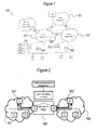
- FIG. 1 illustrates an exemplary network 100 according to the G.hn network architecture.
- a G.hn network is designed to operate over a variety of in-house physical media, including twisted pairs, power lines, and coaxial cabling, in a frequency band from close to DC up to 100 MHz.
- G.hn networks are standardized to use Orthogonal Frequency Division Modulation (OFDM), a modulation scheme which is also common in wireless systems such as IEEE 802.11 wireless local area networks. While our analysis has shown that the scheme of the invention works well in networks with OFDM-based data transmission, the skilled person will appreciate that the choice of modulation scheme does not affect the applicability of the inventive concept.
- the present invention may equally be applied to networks using other modulation schemes, including single-carrier schemes (e.g., quadrature amplitude modulation - QAM), code division multiple access (CDMA), discrete multi-tone (DMT), etc.
- single-carrier schemes e.g., quadrature amplitude modulation - QAM
- Each of the different types of physical media defines a "domain" within the G.hn network.
- a G.hn network may additionally interact with a wireless domain.
- three domains 101 , 102 , 103 are shown in Figure 1 .
- a number of inter-domain bridges (IDB) are shown, of which we will henceforth focus, without loss of generality, on the inter-domain bridge 400 present between a first domain 101 and a second domain 102 .
- each such domain there may be a large number of devices or terminals communicating with each other.
- bidirectional communication is enabled by means of a collision avoidance scheme.
- a first domain master 111 manages the first domain 101
- a second domain master 112 manages the second domain 102 .
- the present invention is based inter alia on the insight that the involvement of the domain master in inter-domain communication between any pair of terminals residing in different domains causes serious scalability issues.
- G.hn supports multi-port device functionality that can be exploited to enable efficient inter-domain bi-directional transmission. Considering the two terminals 501 , 502 , with identical parameters but different service flow priority, the higher priority flow will be given lower delay.
- the available bandwidth may not be sufficient for all the service flows and consequently, service flows with higher priority will be assigned bandwidth resources at the cost of service flows with lower priority.
- this approach may have long latency since the queuing between the domains can reduce the spectrum efficiency with increased costs and complexity. For example, if the available bandwidth is adequate to provide a single 100 Mbps transmission at a time, while two devices are in a waiting list with the same priority level one of the devices will have to wait to utilize the spectrum over the inter-domain bridge 400 .
- a joint use of prioritizing and inter-domain bi-directional mechanism can be used to improve the spectrum efficiency, where the bi-directional scheme is initiated through the logical link control (LLC) function.
- LLC logical link control
- a flow priority and queuing list are used in a sense of control parameters.
- a list of partner devices (each from a different domain) is formed, which is called "partner list”.
- partner list By choosing a pairs of devices from the partner list, the LLC function triggers a new logical interface (henceforth X-I controller) to initiate the inter-domain mechanism.
- the network device parameters such as latency or/and jitter can be used as additional parameters to initiate the communication.
- the two terminals 501 , 502 ask for the network resources to achieve data communication of 100 Mbps.
- the X-I interface coordinates the transmission at the same time between a pair of devices from the partner list by allocating the network resources (i.e., time signaling intervals) for data transmission of 100 Mbps.
- two devices are ready to start communication over the designated inter-domain bridge 400 by using the allocated time signaling intervals.
- both devices A1 and B1 send their full (100 Mbps) data signals to the corresponding multi-port domain managers 111 , 112 , which are interconnected over the LLC function with designated inter-domain bridge node 400 .
- the inter-domain bridge 400 sends commands to the first domain manager 111 and the second domain manager 112 to broadcast the superimposed signal within their corresponding network domains 101 , 102 . Since both the first terminal 501 and the second terminal 502 know their own signals, they are able to subtract their information content and obtain the information from the partner device.
- the inter-domain bridge 400 through the X-I interface, is able to initiate and coordinate bi-directional communication between two devices 501 , 502 from different domains 101 , 102 .
- the methods and apparatus according to the invention therefore provide more efficient use of network resources, by carrying out the data relaying at the inter-domain bridges simultaneously in both direction.
- the present invention is thus based inter alia on the insight that simultaneous transmission of different signals does not necessarily obscure the content of the message, because a transmitter can use its own copy of the transmitted message as a filter to extract the peer's message from the combined transmission.
- the terminals 501 , 502 apply a form of crosstalk cancellation or echo cancellation, in which the terminal's own previously transmitted signal is assumed to be the disturber.
- the inter-domain bridge 400 can ensure that pairs of signals originating from a given pair of terminals 501 , 502 are always sent simultaneously, which ensures that the intended recipient will always be able to disentangle communications addressed to it.
- Other terminals that receive the mixed communication via the broadcast channel will normally not be able to disentangle the communication, as they normally don't dispose of a copy of the outgoing communication signal.
- the invention is further based on the insight that the mixing of communication signals, and thus also their disentanglement, may happen at physical layer, or at the packet level.
- the combining/disentangling may consist of applying a logical XOR operation to the two available signals in a bit-by-bit basis.
- Figure 3 provides a flow chart of an embodiment of the methods according to the present invention. For clarity reasons, steps carried out by an exemplary terminal 500 according to the present invention are illustrated in the left-hand column, while steps carried out by an exemplary inter-domain bridge 400 according to the present invention are illustrated in the right-hand column. The steps of the terminal's peer in the conversation are not explicitly shown.
- a first step 310 the terminal 500 transmits a first communication signal to inter-domain bridge 400 .
- This step corresponds to the first step 320 occurring at the inter-domain bridge 400 , which consists of receiving this first communication signal.
- the inter-domain bridge 400 receives a second communication signal, as a result of a transmission by a second terminal (not shown).
- the aforementioned steps 310-330 may occur substantially simultaneously.
- the inter-domain bridge 400 In a next step 340 , the inter-domain bridge 400 generates a superimposed signal based on the first and second signals.
- the superposition may take place at the packet level, e.g. by the application of a bitwise XOR as mentioned above, or at the physical level, by adding voltage levels or light intensities representing the respective signals.
- the superimposed signals are retransmitted by the inter-domain bridge 400 to the end points 501 , 502 (typically via the respective domain managers 511 , 512 ) .
- Figure 4 provides a block diagram of an embodiment of the inter-domain bridge 400 according to the present invention. It comprises a first interface 410 adapted to exchange signals with a first home networking segment (not shown, see 101 in Figures 1 and 2 ), a second interface 420 adapted to exchange signals with a second home networking segment (not shown, see 101 in Figures 1 and 2 ), and a superposition agent 430 , configured to generate a superimposed signal of the first communication signal and the second communication signal, and to substantially simultaneously transmit said superimposed signal through the first interface 410 and the second interface 420 .
- a superposition agent 430 configured to generate a superimposed signal of the first communication signal and the second communication signal, and to substantially simultaneously transmit said superimposed signal through the first interface 410 and the second interface 420 .
- the interfaces 410 , 420 comprise a combination of the necessary hardware and software to allow communication of the inter-domain bridge 400 with the network segment under consideration using the applicable protocols.
- the superposition agent 430 is operatively coupled to the interfaces 410 , 420 , i.e. it is enabled to transmit and receive communication packets through these interfaces, hence the required minimal receiving and transmitting functions are implicitly present in the superposition agent 430 .
- the first interface 410 is preferably configured to operate over one of a twisted-pair segment, a coax segment (for instance according to the MOCA standard), and a power line segment.
- the second interface 420 is preferably configured to operate over another one of a twisted-pair segment, a coax segment (for instance according to the MOCA standard), and a power line segment.
- Figure 5 provides a block diagram of an embodiment of the communication terminal 500 according to the present invention. It comprises a communication interface 510 for exchanging signals with an inter-domain bridge 400 via a home network domain 101 ; a transmitter 520 for transmitting an outgoing communication signal through the communication interface 510 ; a receiver 530 for receiving an incoming communication signal through the communication interface 510 ; and means 540 for removing a component corresponding to the outgoing communication signal from the incoming communication signal in order to arrive at a difference signal 599 .
- the resulting difference signal 599 represents the message of the conversation peer, which is obtained after cancelling the "self-crosstalk" out of the communication signal received from the inter-domain bridge 400 .
- the interface 510 comprises a combination of the necessary hardware and software to allow communication of the terminal 500 with the network segment under consideration using the applicable protocols.
- the extraction means 540 is operatively coupled to the interface 510 , i.e. it is enabled to transmit and receive communication packets through this interface, via transmitter 520 and receiver 530 , respectively.
- the interface 510 is preferably configured to operate over one of a twisted-pair segment, a coax segment (for instance according to the MOCA standard), and a power line segment.
- the superposition agent 430 is represented in Figure 4 by means of certain logical processing symbols, this is done for illustrative purposes only, and not to limit the invention to this particular form of signal mixing. The same applies to the corresponding logical symbols used to represent the means for removing a signal component 540 in Figure 5 .
- processors may be provided through the use of dedicated hardware as well as hardware capable of executing software in association with appropriate software.
- the functions may be provided by a single dedicated processor, by a single shared processor, or by a plurality of individual processors, some of which may be shared.
- explicit use of the term "processor” or “controller” should not be construed to refer exclusively to hardware capable of executing software, and may implicitly include, without limitation, digital signal processor (DSP) hardware, network processor, application specific integrated circuit (ASIC), field programmable gate array (FPGA), read only memory (ROM) for storing software, random access memory (RAM), and non volatile storage.
- DSP digital signal processor
- ASIC application specific integrated circuit
- FPGA field programmable gate array
- ROM read only memory
- RAM random access memory
- any switches shown in the FIGS. are conceptual only. Their function may be carried out through the operation of program logic, through dedicated logic, through the interaction of program control and dedicated logic, or even manually, the particular technique being selectable by the implementer as more specifically understood from the context.
- program storage devices e.g., digital data storage media, which are machine or computer readable and encode machine-executable or computer-executable programs of instructions, wherein said instructions perform some or all of the steps of said above-described methods.
- the program storage devices may be, e.g., digital memories, magnetic storage media such as a magnetic disks and magnetic tapes, hard drives, or optically readable digital data storage media.
- the embodiments are also intended to cover computers programmed to perform said steps of the above-described methods.
Claims (14)
- Procédé pour fournir une communication bidirectionnelle entre des segments d'un réseau domestique, le procédé comprenant les étapes suivantes :recevoir un premier signal de communication au niveau d'une première interface d'un pont inter-domaine pendant un premier intervalle de temps ;recevoir un deuxième signal de communication au niveau d'une deuxième interface dudit pont inter-domaine pendant ledit premier intervalle de temps ;générer un signal superposé dudit premier signal de communication et dudit deuxième signal de communication ;transmettre ledit signal superposé par l'intermédiaire de ladite première interface et de ladite deuxième interface pendant un deuxième intervalle de temps, ledit deuxième intervalle de temps succédant audit premier intervalle de temps.
- Procédé selon la revendication 1, dans lequel ladite génération dudit signal superposé comprend la combinaison de contenus de données binaires dudit premier signal de communication avec des contenus de données binaires dudit deuxième signal de communication en appliquant une opération OU exclusif.
- Procédé selon la revendication 1, dans lequel ladite génération dudit signal superposé comprend l'ajout d'un premier paramètre physique représentant ledit premier signal de communication à un deuxième paramètre physique représentant ledit deuxième signal de communication dans le domaine temporel.
- Procédé pour communiquer avec un terminal dans un segment différent d'un réseau domestique, le procédé comprenant les étapes suivantes :transmettre un premier signal de communication à un pont inter-domaine pendant un premier intervalle de temps ;recevoir un deuxième signal de communication à partir dudit pont inter-domaine pendant un deuxième intervalle de temps ;combiner ledit premier signal de communication transmis et ledit deuxième signal de communication reçu pour extraire un troisième signal de communication, correspondant à une transmission à partir dudit terminal distant reçue au niveau dudit pont inter-domaine.
- Procédé selon la revendication 4, dans lequel ladite combinaison dudit premier signal de communication et dudit deuxième signal de communication comprend la combinaison de contenus de données binaires dudit premier signal de communication avec des contenus de données binaires dudit deuxième signal de communication en appliquant une opération OU exclusif.
- Procédé selon la revendication 4, dans lequel ladite combinaison dudit premier signal de communication et dudit deuxième signal de communication comprend la soustraction d'un premier paramètre physique représentant ledit premier signal de communication d'un deuxième paramètre physique représentant ledit deuxième signal de communication dans le domaine temporel.
- Programme informatique configuré pour entraîner l'exécution du procédé par le processeur selon l'une quelconque des revendications précédentes.
- Pont inter-domaine comprenant :une première interface adaptée pour échanger des signaux avec un premier segment de réseau domestique,une deuxième interface adaptée pour échanger des signaux avec un deuxième segment de réseau domestique,un agent de superposition, couplé de manière opérationnelle à ladite première interface et à ladite deuxième interface, ledit agent de superposition étant configuré pour générer un signal superposé d'un premier signal de communication provenant de ladite première interface et d'un deuxième signal de communication provenant de ladite deuxième interface, et pour transmettre pratiquement simultanément ledit signal superposé par l'intermédiaire de ladite première interface et de ladite deuxième interface.
- Pont inter-domaine selon la revendication 8, dans lequel ledit signal superposé comprend une combinaison de contenus de données binaires dudit premier signal de communication avec des contenus de données binaires dudit deuxième signal de communication obtenue en appliquant une opération OU exclusif.
- Pont inter-domaine selon la revendication 8, dans lequel ledit signal superposé comprend un ajout d'un premier paramètre physique représentant ledit premier signal de communication à un deuxième paramètre physique représentant ledit deuxième signal de communication dans le domaine temporel.
- Terminal de communication comprenant :une interface de communication pour échanger des signaux avec un pont inter-domaine par l'intermédiaire d'un domaine de réseau domestique ;un émetteur pour transmettre un signal de communication sortant par l'intermédiaire de ladite interface de communication ;un récepteur pour recevoir un signal de communication entrant par l'intermédiaire de ladite interface de communication ; etdes moyens pour retirer une composante correspondant audit signal de communication sortant dudit signal de communication entrant afin d'arriver à un signal de différence.
- Terminal de communication selon la revendication 11, dans lequel ledit signal de différence est une combinaison de contenus de données binaires dudit signal de communication entrant avec des contenus de données binaires dudit signal de communication sortant obtenue en appliquant une opération OU exclusif.
- Terminal de communication selon la revendication 11, dans lequel ledit signal de différence est une différence entre un premier paramètre physique représentant ledit signal de communication entrant et un deuxième paramètre physique représentant ledit signal de communication sortant dans le domaine temporel.
- Système comprenant un pont inter-domaine selon la revendication 8 et deux terminaux de communication selon la revendication 11, lesdits deux terminaux de communication étant connectés à ladite première interface et à ladite deuxième interface.
Priority Applications (6)
| Application Number | Priority Date | Filing Date | Title |
|---|---|---|---|
| EP11305586.7A EP2525533B1 (fr) | 2011-05-16 | 2011-05-16 | Procédé et appareil pour fournir une communication bidirectionnelle entre segments d'un réseau domestique |
| CN201280023597.0A CN103534986B (zh) | 2011-05-16 | 2012-05-07 | 用于在家庭网络的分段之间提供双向通信的方法和装置 |
| US14/112,150 US9749118B2 (en) | 2011-05-16 | 2012-05-07 | Method and apparatus for providing bidirectional communication between segments of a home network |
| JP2014510727A JP6139513B2 (ja) | 2011-05-16 | 2012-05-07 | ホームネットワークのセグメント間における双方向通信を提供するための方法および装置 |
| PCT/EP2012/058346 WO2012156222A1 (fr) | 2011-05-16 | 2012-05-07 | Procédé et dispositif de mise en œuvre d'une communication bidirectionnelle entre des segments de réseau domestique |
| KR1020137030402A KR101500256B1 (ko) | 2011-05-16 | 2012-05-07 | 홈 네트워크의 세그먼트들 사이에 양방향 통신을 제공하기 위한 방법 및 장치 |
Applications Claiming Priority (1)
| Application Number | Priority Date | Filing Date | Title |
|---|---|---|---|
| EP11305586.7A EP2525533B1 (fr) | 2011-05-16 | 2011-05-16 | Procédé et appareil pour fournir une communication bidirectionnelle entre segments d'un réseau domestique |
Publications (2)
| Publication Number | Publication Date |
|---|---|
| EP2525533A1 EP2525533A1 (fr) | 2012-11-21 |
| EP2525533B1 true EP2525533B1 (fr) | 2014-02-26 |
Family
ID=46025757
Family Applications (1)
| Application Number | Title | Priority Date | Filing Date |
|---|---|---|---|
| EP11305586.7A Active EP2525533B1 (fr) | 2011-05-16 | 2011-05-16 | Procédé et appareil pour fournir une communication bidirectionnelle entre segments d'un réseau domestique |
Country Status (6)
| Country | Link |
|---|---|
| US (1) | US9749118B2 (fr) |
| EP (1) | EP2525533B1 (fr) |
| JP (1) | JP6139513B2 (fr) |
| KR (1) | KR101500256B1 (fr) |
| CN (1) | CN103534986B (fr) |
| WO (1) | WO2012156222A1 (fr) |
Families Citing this family (1)
| Publication number | Priority date | Publication date | Assignee | Title |
|---|---|---|---|---|
| EP2571199B1 (fr) | 2011-09-19 | 2015-04-29 | Alcatel Lucent | Procédé et appareil pour évaluer la qualité d'un canal de communication dans un réseau de domaines multiples |
Family Cites Families (48)
| Publication number | Priority date | Publication date | Assignee | Title |
|---|---|---|---|---|
| JPS6129735A (ja) | 1984-07-20 | 1986-02-10 | Jeol Ltd | 応力画像表示装置 |
| JPH0358658A (ja) * | 1989-07-27 | 1991-03-13 | Nec Corp | 分散会議システム |
| JPH0787576B2 (ja) * | 1990-05-31 | 1995-09-20 | 日本電気株式会社 | テレビ会議装置 |
| JP3058658B2 (ja) | 1990-06-21 | 2000-07-04 | 国際電気株式会社 | 半導体製造装置 |
| JPH0484553A (ja) * | 1990-07-26 | 1992-03-17 | Nec Corp | 音声ミキシング装置 |
| JP2700514B2 (ja) * | 1992-05-12 | 1998-01-21 | 日比谷総合設備株式会社 | 映像会議システム |
| JP3573850B2 (ja) * | 1995-10-17 | 2004-10-06 | ヒューレット・パッカード・カンパニー | ビデオ会議システム |
| US5917820A (en) * | 1996-06-10 | 1999-06-29 | Cisco Technology, Inc. | Efficient packet forwarding arrangement for routing packets in an internetwork |
| JPH10112760A (ja) * | 1996-10-08 | 1998-04-28 | Fujitsu Ltd | 音質劣化防止方式 |
| US6392997B1 (en) * | 1999-03-16 | 2002-05-21 | Cisco Technology, Inc. | Technique for group-based routing update with limited per neighbor/adjacency customization |
| GB9916173D0 (en) * | 1999-07-09 | 1999-09-08 | Madge Networks Ltd | Interconnecting network domains |
| JP2001044969A (ja) * | 1999-08-02 | 2001-02-16 | Mitsubishi Electric Corp | 移動体通信システム、基地局および移動通信端末、ならびに再送制御方法 |
| US7123620B1 (en) * | 2000-04-25 | 2006-10-17 | Cisco Technology, Inc. | Apparatus and method for scalable and dynamic traffic engineering in a data communication network |
| JP3461157B2 (ja) * | 2000-05-29 | 2003-10-27 | 松下電器産業株式会社 | マルチキャリア通信装置およびマルチキャリア通信方法 |
| DE10032427A1 (de) * | 2000-07-04 | 2002-01-24 | Siemens Ag | Verfahren und Vorrichtung zum Auswerten eines Funksignals |
| EP1720277B1 (fr) * | 2000-07-05 | 2017-09-27 | Sony Deutschland Gmbh | Schéma de symboles pilotes pour plusieurs antennes dans un système OFDM |
| CN1276595C (zh) * | 2000-08-30 | 2006-09-20 | 松下电器产业株式会社 | 数据传送装置、无线电通信系统及无线电通信方法 |
| JP3462468B2 (ja) * | 2000-11-27 | 2003-11-05 | 松下電器産業株式会社 | Ofdm受信装置、ofdm送信装置およびofdm通信方法 |
| JP2002185943A (ja) * | 2000-12-12 | 2002-06-28 | Nec Corp | 放送視聴方法、放送送信サーバ、携帯端末及び多地点通話・放送制御視聴装置 |
| GB0118158D0 (en) * | 2001-07-25 | 2001-09-19 | Marconi Comm Ltd | Telecommunications and data communications switching apparatus and method |
| US7463577B2 (en) * | 2002-04-09 | 2008-12-09 | Panasonic Corporation | OFDM communication method and OFDM communication device |
| JP3780976B2 (ja) * | 2002-05-24 | 2006-05-31 | 日本電気株式会社 | 電子コンテンツ閲覧装置及び電子コンテンツ閲覧方法 |
| US20030223379A1 (en) * | 2002-05-28 | 2003-12-04 | Xuguang Yang | Method and system for inter-domain loop protection using a hierarchy of loop resolving protocols |
| KR100547758B1 (ko) * | 2003-02-28 | 2006-01-31 | 삼성전자주식회사 | 초광대역 통신 시스템의 프리앰블 송수신 장치 및 방법 |
| JP4141885B2 (ja) * | 2003-04-17 | 2008-08-27 | 株式会社リコー | シリアル通信装置 |
| JP2005057373A (ja) * | 2003-08-07 | 2005-03-03 | Ntt Docomo Inc | 無線パケット通信装置 |
| US7634554B2 (en) * | 2003-09-18 | 2009-12-15 | Cisco Technology, Inc. | TTL exploration technique for determining capabilities and configuration of a peer router |
| US20050071469A1 (en) * | 2003-09-26 | 2005-03-31 | Mccollom William G. | Method and system for controlling egress traffic load balancing between multiple service providers |
| JP4426249B2 (ja) * | 2003-10-27 | 2010-03-03 | パイオニア株式会社 | 信号伝送装置及び伝送方法 |
| EP2242231A1 (fr) * | 2003-11-12 | 2010-10-20 | Qualcomm Incorporated | Interface à débit de données élevé doté d'un contrôle de lien amélioré |
| US7242976B2 (en) * | 2004-04-02 | 2007-07-10 | Oki Electric Industry Co., Ltd. | Device and method for selecting codes |
| US8184657B2 (en) * | 2004-09-23 | 2012-05-22 | Sony Corporation | Reliable audio-video transmission system using multi-media diversity |
| JP4661447B2 (ja) * | 2005-08-16 | 2011-03-30 | ソニー株式会社 | 送受信システムおよび方法、送信装置および方法、受信装置および方法、並びに、プログラム |
| JP5265383B2 (ja) * | 2005-09-07 | 2013-08-14 | ヴィドヨ,インコーポレーテッド | 低遅延かつ分散した会議アプリケーション向けコンファレンスサーバアーキテクチャのためのシステムおよび方法 |
| US8406239B2 (en) * | 2005-10-03 | 2013-03-26 | Broadcom Corporation | Multi-wideband communications over multiple mediums |
| JP4479647B2 (ja) * | 2005-11-21 | 2010-06-09 | 日本電気株式会社 | 経路生成システム、経路生成方法、経路管理サーバ、中継装置、端末装置および制御プログラム |
| CN101106435B (zh) * | 2006-07-10 | 2011-08-03 | 华为技术有限公司 | 一种多对线共同传输的方法及发送端和接收端 |
| JP2008141348A (ja) * | 2006-11-30 | 2008-06-19 | Yamaha Corp | 通信装置 |
| US20080219251A1 (en) * | 2007-03-08 | 2008-09-11 | Feng Xue | Combining packets in physical layer for two-way relaying |
| US8203983B2 (en) * | 2007-03-15 | 2012-06-19 | Lantiq Deutschland Gmbh | Multi-domain network with centralized management |
| WO2008152800A1 (fr) * | 2007-06-13 | 2008-12-18 | Sanyo Electric Co., Ltd. | Dispositif radio et système de mesure l'utilisant |
| JP2009065336A (ja) * | 2007-09-05 | 2009-03-26 | Hitachi Communication Technologies Ltd | テレビ会議システム |
| US8050213B2 (en) * | 2007-09-17 | 2011-11-01 | Lg Electronics, Inc. | Message coding in a relayed communications network |
| CN101370115A (zh) * | 2008-10-20 | 2009-02-18 | 深圳华为通信技术有限公司 | 会议终端、会议服务器、会议系统及数据处理方法 |
| JP2009065696A (ja) * | 2008-10-27 | 2009-03-26 | Toshiba Corp | 映像合成装置、方法およびプログラム |
| US8009993B2 (en) * | 2008-12-10 | 2011-08-30 | Pmc-Sierra Israel Ltd. | Hybrid balanced coding scheme |
| US20120246331A1 (en) * | 2010-01-11 | 2012-09-27 | Peter Heller | Dynamic multimode home networking modem device |
| US20120226901A1 (en) * | 2010-09-02 | 2012-09-06 | Lantiq Deutschland Gmbh | System, Method and Apparatus For Secure Telecommunications In A Home Area Network |
-
2011
- 2011-05-16 EP EP11305586.7A patent/EP2525533B1/fr active Active
-
2012
- 2012-05-07 US US14/112,150 patent/US9749118B2/en active Active
- 2012-05-07 CN CN201280023597.0A patent/CN103534986B/zh active Active
- 2012-05-07 WO PCT/EP2012/058346 patent/WO2012156222A1/fr active Application Filing
- 2012-05-07 KR KR1020137030402A patent/KR101500256B1/ko active IP Right Grant
- 2012-05-07 JP JP2014510727A patent/JP6139513B2/ja active Active
Also Published As
| Publication number | Publication date |
|---|---|
| JP2014520423A (ja) | 2014-08-21 |
| KR20140002058A (ko) | 2014-01-07 |
| CN103534986B (zh) | 2018-12-04 |
| WO2012156222A1 (fr) | 2012-11-22 |
| US9749118B2 (en) | 2017-08-29 |
| KR101500256B1 (ko) | 2015-03-06 |
| EP2525533A1 (fr) | 2012-11-21 |
| US20140064157A1 (en) | 2014-03-06 |
| CN103534986A (zh) | 2014-01-22 |
| JP6139513B2 (ja) | 2017-05-31 |
Similar Documents
| Publication | Publication Date | Title |
|---|---|---|
| US8488627B2 (en) | Multi-communications-media network device | |
| KR20210024649A (ko) | 네트워크 슬라이스 제어 방법 및 장치 그리고 컴퓨터 판독 가능한 저장 매체 | |
| US20100020784A1 (en) | Apparatus, network and method for implementing tdm channels over a csma shared media network | |
| CN103916275A (zh) | 一种bfd检测装置和方法 | |
| EP2493085A1 (fr) | Coexistence dans un système de communication | |
| WO2016019557A1 (fr) | Procédé d'attribution de ressource, procédé et dispositif de communication par liaison directe avec un utilisateur | |
| EP2733857B1 (fr) | Procédé et appareil pour retransmettre des messages dans un réseau CPL | |
| EP3768011B1 (fr) | Procédé et dispositif de transmission d'informations de commande de liaison montante | |
| EP2525533B1 (fr) | Procédé et appareil pour fournir une communication bidirectionnelle entre segments d'un réseau domestique | |
| JP6465971B2 (ja) | 通信システムのための加入者局、及び、高データレートのcanベースの通信方法 | |
| EP3128710B1 (fr) | Procédé pour la communication de synchronisation dans un réseau d'accès auquel la technologie g.hn s'applique, et concentrateur de lignes de réseau d'accès, terminal de réseau d'accès et système de réseau d'accès utilisant un tel procédé | |
| US9413601B2 (en) | Channel reuse among communication networks sharing a communication channel | |
| WO2019128374A1 (fr) | Procédé et appareil de traitement de signal d'initialisation | |
| US10541829B2 (en) | Network devices for scalable point to multipoint networks | |
| EP2571199B1 (fr) | Procédé et appareil pour évaluer la qualité d'un canal de communication dans un réseau de domaines multiples | |
| US11937167B1 (en) | Client modification of traffic table in multi channel Wi-Fi | |
| Khan | Delay measurements In live 5G cellular network | |
| CN101888321A (zh) | 以太网多点接入方法、以太网系统以及设备 | |
| CN111131134A (zh) | 轨道交通列车车载以太网数据交换装置 | |
| Yang et al. | Partial self-interference cancellation with frame pre-aliasing method for full-duplex DF system | |
| CN105791168A (zh) | 网络资源获取方法及装置 |
Legal Events
| Date | Code | Title | Description |
|---|---|---|---|
| PUAI | Public reference made under article 153(3) epc to a published international application that has entered the european phase |
Free format text: ORIGINAL CODE: 0009012 |
|
| AK | Designated contracting states |
Kind code of ref document: A1 Designated state(s): AL AT BE BG CH CY CZ DE DK EE ES FI FR GB GR HR HU IE IS IT LI LT LU LV MC MK MT NL NO PL PT RO RS SE SI SK SM TR |
|
| AX | Request for extension of the european patent |
Extension state: BA ME |
|
| 17P | Request for examination filed |
Effective date: 20130521 |
|
| GRAP | Despatch of communication of intention to grant a patent |
Free format text: ORIGINAL CODE: EPIDOSNIGR1 |
|
| 111Z | Information provided on other rights and legal means of execution |
Free format text: AL AT BE BG CH CY CZ DE DK EE ES FI FR GB GR HR HU IE IS IT LI LT LU LV MC MK MT NL NO PL PT RO RS SE SI SK SM TR Effective date: 20130410 |
|
| INTG | Intention to grant announced |
Effective date: 20130920 |
|
| GRAS | Grant fee paid |
Free format text: ORIGINAL CODE: EPIDOSNIGR3 |
|
| GRAA | (expected) grant |
Free format text: ORIGINAL CODE: 0009210 |
|
| AK | Designated contracting states |
Kind code of ref document: B1 Designated state(s): AL AT BE BG CH CY CZ DE DK EE ES FI FR GB GR HR HU IE IS IT LI LT LU LV MC MK MT NL NO PL PT RO RS SE SI SK SM TR |
|
| REG | Reference to a national code |
Ref country code: GB Ref legal event code: FG4D |
|
| RIN1 | Information on inventor provided before grant (corrected) |
Inventor name: GACANIN, HARIS |
|
| REG | Reference to a national code |
Ref country code: CH Ref legal event code: EP |
|
| REG | Reference to a national code |
Ref country code: AT Ref legal event code: REF Ref document number: 654140 Country of ref document: AT Kind code of ref document: T Effective date: 20140315 |
|
| REG | Reference to a national code |
Ref country code: IE Ref legal event code: FG4D |
|
| REG | Reference to a national code |
Ref country code: DE Ref legal event code: R096 Ref document number: 602011005069 Country of ref document: DE Effective date: 20140410 |
|
| REG | Reference to a national code |
Ref country code: GB Ref legal event code: 732E Free format text: REGISTERED BETWEEN 20140529 AND 20140604 |
|
| REG | Reference to a national code |
Ref country code: NL Ref legal event code: VDEP Effective date: 20140226 |
|
| REG | Reference to a national code |
Ref country code: AT Ref legal event code: MK05 Ref document number: 654140 Country of ref document: AT Kind code of ref document: T Effective date: 20140226 |
|
| REG | Reference to a national code |
Ref country code: LT Ref legal event code: MG4D |
|
| PG25 | Lapsed in a contracting state [announced via postgrant information from national office to epo] |
Ref country code: LT Free format text: LAPSE BECAUSE OF FAILURE TO SUBMIT A TRANSLATION OF THE DESCRIPTION OR TO PAY THE FEE WITHIN THE PRESCRIBED TIME-LIMIT Effective date: 20140226 Ref country code: NO Free format text: LAPSE BECAUSE OF FAILURE TO SUBMIT A TRANSLATION OF THE DESCRIPTION OR TO PAY THE FEE WITHIN THE PRESCRIBED TIME-LIMIT Effective date: 20140526 Ref country code: IS Free format text: LAPSE BECAUSE OF FAILURE TO SUBMIT A TRANSLATION OF THE DESCRIPTION OR TO PAY THE FEE WITHIN THE PRESCRIBED TIME-LIMIT Effective date: 20140626 |
|
| REG | Reference to a national code |
Ref country code: CH Ref legal event code: PCOW Free format text: NEW ADDRESS: 148/152 ROUTE DE LA REINE, 92100 BOULOGNE-BILLANCOURT (FR) |
|
| REG | Reference to a national code |
Ref country code: FR Ref legal event code: GC Effective date: 20140602 |
|
| RAP2 | Party data changed (patent owner data changed or rights of a patent transferred) |
Owner name: ALCATEL LUCENT |
|
| PG25 | Lapsed in a contracting state [announced via postgrant information from national office to epo] |
Ref country code: FI Free format text: LAPSE BECAUSE OF FAILURE TO SUBMIT A TRANSLATION OF THE DESCRIPTION OR TO PAY THE FEE WITHIN THE PRESCRIBED TIME-LIMIT Effective date: 20140226 Ref country code: PT Free format text: LAPSE BECAUSE OF FAILURE TO SUBMIT A TRANSLATION OF THE DESCRIPTION OR TO PAY THE FEE WITHIN THE PRESCRIBED TIME-LIMIT Effective date: 20140626 Ref country code: CY Free format text: LAPSE BECAUSE OF FAILURE TO SUBMIT A TRANSLATION OF THE DESCRIPTION OR TO PAY THE FEE WITHIN THE PRESCRIBED TIME-LIMIT Effective date: 20140226 Ref country code: AT Free format text: LAPSE BECAUSE OF FAILURE TO SUBMIT A TRANSLATION OF THE DESCRIPTION OR TO PAY THE FEE WITHIN THE PRESCRIBED TIME-LIMIT Effective date: 20140226 Ref country code: NL Free format text: LAPSE BECAUSE OF FAILURE TO SUBMIT A TRANSLATION OF THE DESCRIPTION OR TO PAY THE FEE WITHIN THE PRESCRIBED TIME-LIMIT Effective date: 20140226 Ref country code: SE Free format text: LAPSE BECAUSE OF FAILURE TO SUBMIT A TRANSLATION OF THE DESCRIPTION OR TO PAY THE FEE WITHIN THE PRESCRIBED TIME-LIMIT Effective date: 20140226 |
|
| PG25 | Lapsed in a contracting state [announced via postgrant information from national office to epo] |
Ref country code: HR Free format text: LAPSE BECAUSE OF FAILURE TO SUBMIT A TRANSLATION OF THE DESCRIPTION OR TO PAY THE FEE WITHIN THE PRESCRIBED TIME-LIMIT Effective date: 20140226 Ref country code: BE Free format text: LAPSE BECAUSE OF FAILURE TO SUBMIT A TRANSLATION OF THE DESCRIPTION OR TO PAY THE FEE WITHIN THE PRESCRIBED TIME-LIMIT Effective date: 20140226 Ref country code: LV Free format text: LAPSE BECAUSE OF FAILURE TO SUBMIT A TRANSLATION OF THE DESCRIPTION OR TO PAY THE FEE WITHIN THE PRESCRIBED TIME-LIMIT Effective date: 20140226 |
|
| PG25 | Lapsed in a contracting state [announced via postgrant information from national office to epo] |
Ref country code: CZ Free format text: LAPSE BECAUSE OF FAILURE TO SUBMIT A TRANSLATION OF THE DESCRIPTION OR TO PAY THE FEE WITHIN THE PRESCRIBED TIME-LIMIT Effective date: 20140226 Ref country code: EE Free format text: LAPSE BECAUSE OF FAILURE TO SUBMIT A TRANSLATION OF THE DESCRIPTION OR TO PAY THE FEE WITHIN THE PRESCRIBED TIME-LIMIT Effective date: 20140226 Ref country code: RO Free format text: LAPSE BECAUSE OF FAILURE TO SUBMIT A TRANSLATION OF THE DESCRIPTION OR TO PAY THE FEE WITHIN THE PRESCRIBED TIME-LIMIT Effective date: 20140226 Ref country code: DK Free format text: LAPSE BECAUSE OF FAILURE TO SUBMIT A TRANSLATION OF THE DESCRIPTION OR TO PAY THE FEE WITHIN THE PRESCRIBED TIME-LIMIT Effective date: 20140226 |
|
| REG | Reference to a national code |
Ref country code: DE Ref legal event code: R097 Ref document number: 602011005069 Country of ref document: DE |
|
| PG25 | Lapsed in a contracting state [announced via postgrant information from national office to epo] |
Ref country code: PL Free format text: LAPSE BECAUSE OF FAILURE TO SUBMIT A TRANSLATION OF THE DESCRIPTION OR TO PAY THE FEE WITHIN THE PRESCRIBED TIME-LIMIT Effective date: 20140226 Ref country code: SK Free format text: LAPSE BECAUSE OF FAILURE TO SUBMIT A TRANSLATION OF THE DESCRIPTION OR TO PAY THE FEE WITHIN THE PRESCRIBED TIME-LIMIT Effective date: 20140226 Ref country code: ES Free format text: LAPSE BECAUSE OF FAILURE TO SUBMIT A TRANSLATION OF THE DESCRIPTION OR TO PAY THE FEE WITHIN THE PRESCRIBED TIME-LIMIT Effective date: 20140226 |
|
| REG | Reference to a national code |
Ref country code: FR Ref legal event code: RG Effective date: 20141016 |
|
| PG25 | Lapsed in a contracting state [announced via postgrant information from national office to epo] |
Ref country code: LU Free format text: LAPSE BECAUSE OF FAILURE TO SUBMIT A TRANSLATION OF THE DESCRIPTION OR TO PAY THE FEE WITHIN THE PRESCRIBED TIME-LIMIT Effective date: 20140516 |
|
| REG | Reference to a national code |
Ref country code: CH Ref legal event code: PL |
|
| PLBE | No opposition filed within time limit |
Free format text: ORIGINAL CODE: 0009261 |
|
| STAA | Information on the status of an ep patent application or granted ep patent |
Free format text: STATUS: NO OPPOSITION FILED WITHIN TIME LIMIT |
|
| PG25 | Lapsed in a contracting state [announced via postgrant information from national office to epo] |
Ref country code: MC Free format text: LAPSE BECAUSE OF FAILURE TO SUBMIT A TRANSLATION OF THE DESCRIPTION OR TO PAY THE FEE WITHIN THE PRESCRIBED TIME-LIMIT Effective date: 20140226 Ref country code: LI Free format text: LAPSE BECAUSE OF NON-PAYMENT OF DUE FEES Effective date: 20140531 Ref country code: CH Free format text: LAPSE BECAUSE OF NON-PAYMENT OF DUE FEES Effective date: 20140531 |
|
| 26N | No opposition filed |
Effective date: 20141127 |
|
| REG | Reference to a national code |
Ref country code: IE Ref legal event code: MM4A |
|
| REG | Reference to a national code |
Ref country code: DE Ref legal event code: R097 Ref document number: 602011005069 Country of ref document: DE Effective date: 20141127 |
|
| PG25 | Lapsed in a contracting state [announced via postgrant information from national office to epo] |
Ref country code: IT Free format text: LAPSE BECAUSE OF FAILURE TO SUBMIT A TRANSLATION OF THE DESCRIPTION OR TO PAY THE FEE WITHIN THE PRESCRIBED TIME-LIMIT Effective date: 20140226 |
|
| PG25 | Lapsed in a contracting state [announced via postgrant information from national office to epo] |
Ref country code: IE Free format text: LAPSE BECAUSE OF NON-PAYMENT OF DUE FEES Effective date: 20140516 |
|
| REG | Reference to a national code |
Ref country code: FR Ref legal event code: PLFP Year of fee payment: 5 |
|
| PG25 | Lapsed in a contracting state [announced via postgrant information from national office to epo] |
Ref country code: SI Free format text: LAPSE BECAUSE OF FAILURE TO SUBMIT A TRANSLATION OF THE DESCRIPTION OR TO PAY THE FEE WITHIN THE PRESCRIBED TIME-LIMIT Effective date: 20140226 |
|
| PG25 | Lapsed in a contracting state [announced via postgrant information from national office to epo] |
Ref country code: MT Free format text: LAPSE BECAUSE OF FAILURE TO SUBMIT A TRANSLATION OF THE DESCRIPTION OR TO PAY THE FEE WITHIN THE PRESCRIBED TIME-LIMIT Effective date: 20140226 |
|
| PG25 | Lapsed in a contracting state [announced via postgrant information from national office to epo] |
Ref country code: SM Free format text: LAPSE BECAUSE OF FAILURE TO SUBMIT A TRANSLATION OF THE DESCRIPTION OR TO PAY THE FEE WITHIN THE PRESCRIBED TIME-LIMIT Effective date: 20140226 |
|
| REG | Reference to a national code |
Ref country code: FR Ref legal event code: PLFP Year of fee payment: 6 |
|
| PG25 | Lapsed in a contracting state [announced via postgrant information from national office to epo] |
Ref country code: GR Free format text: LAPSE BECAUSE OF FAILURE TO SUBMIT A TRANSLATION OF THE DESCRIPTION OR TO PAY THE FEE WITHIN THE PRESCRIBED TIME-LIMIT Effective date: 20140527 Ref country code: BG Free format text: LAPSE BECAUSE OF FAILURE TO SUBMIT A TRANSLATION OF THE DESCRIPTION OR TO PAY THE FEE WITHIN THE PRESCRIBED TIME-LIMIT Effective date: 20140226 Ref country code: RS Free format text: LAPSE BECAUSE OF NON-PAYMENT OF DUE FEES Effective date: 20140226 |
|
| PG25 | Lapsed in a contracting state [announced via postgrant information from national office to epo] |
Ref country code: HU Free format text: LAPSE BECAUSE OF FAILURE TO SUBMIT A TRANSLATION OF THE DESCRIPTION OR TO PAY THE FEE WITHIN THE PRESCRIBED TIME-LIMIT; INVALID AB INITIO Effective date: 20110516 Ref country code: TR Free format text: LAPSE BECAUSE OF FAILURE TO SUBMIT A TRANSLATION OF THE DESCRIPTION OR TO PAY THE FEE WITHIN THE PRESCRIBED TIME-LIMIT Effective date: 20140226 |
|
| REG | Reference to a national code |
Ref country code: FR Ref legal event code: PLFP Year of fee payment: 7 |
|
| REG | Reference to a national code |
Ref country code: FR Ref legal event code: PLFP Year of fee payment: 8 |
|
| PG25 | Lapsed in a contracting state [announced via postgrant information from national office to epo] |
Ref country code: MK Free format text: LAPSE BECAUSE OF FAILURE TO SUBMIT A TRANSLATION OF THE DESCRIPTION OR TO PAY THE FEE WITHIN THE PRESCRIBED TIME-LIMIT Effective date: 20140226 |
|
| PG25 | Lapsed in a contracting state [announced via postgrant information from national office to epo] |
Ref country code: AL Free format text: LAPSE BECAUSE OF FAILURE TO SUBMIT A TRANSLATION OF THE DESCRIPTION OR TO PAY THE FEE WITHIN THE PRESCRIBED TIME-LIMIT Effective date: 20140226 |
|
| REG | Reference to a national code |
Ref country code: FR Ref legal event code: PLFP Year of fee payment: 13 |
|
| PGFP | Annual fee paid to national office [announced via postgrant information from national office to epo] |
Ref country code: GB Payment date: 20230330 Year of fee payment: 13 |
|
| PGFP | Annual fee paid to national office [announced via postgrant information from national office to epo] |
Ref country code: FR Payment date: 20230411 Year of fee payment: 13 Ref country code: DE Payment date: 20230331 Year of fee payment: 13 |