EP2523780B1 - Bohr- und/oder schlaghammer mit kühlung von gerätekomponenten - Google Patents
Bohr- und/oder schlaghammer mit kühlung von gerätekomponenten Download PDFInfo
- Publication number
- EP2523780B1 EP2523780B1 EP11700320.2A EP11700320A EP2523780B1 EP 2523780 B1 EP2523780 B1 EP 2523780B1 EP 11700320 A EP11700320 A EP 11700320A EP 2523780 B1 EP2523780 B1 EP 2523780B1
- Authority
- EP
- European Patent Office
- Prior art keywords
- cooling air
- air flow
- duct
- hammer
- cooling
- Prior art date
- Legal status (The legal status is an assumption and is not a legal conclusion. Google has not performed a legal analysis and makes no representation as to the accuracy of the status listed.)
- Active
Links
Images



Classifications
-
- B—PERFORMING OPERATIONS; TRANSPORTING
- B25—HAND TOOLS; PORTABLE POWER-DRIVEN TOOLS; MANIPULATORS
- B25D—PERCUSSIVE TOOLS
- B25D17/00—Details of, or accessories for, portable power-driven percussive tools
- B25D17/20—Devices for cleaning or cooling tool or work
-
- B—PERFORMING OPERATIONS; TRANSPORTING
- B25—HAND TOOLS; PORTABLE POWER-DRIVEN TOOLS; MANIPULATORS
- B25D—PERCUSSIVE TOOLS
- B25D9/00—Portable percussive tools with fluid-pressure drive, i.e. driven directly by fluids, e.g. having several percussive tool bits operated simultaneously
- B25D9/06—Means for driving the impulse member
- B25D9/10—Means for driving the impulse member comprising a built-in internal-combustion engine
-
- B—PERFORMING OPERATIONS; TRANSPORTING
- B25—HAND TOOLS; PORTABLE POWER-DRIVEN TOOLS; MANIPULATORS
- B25D—PERCUSSIVE TOOLS
- B25D2211/00—Details of portable percussive tools with electromotor or other motor drive
- B25D2211/06—Means for driving the impulse member
- B25D2211/068—Crank-actuated impulse-driving mechanisms
-
- B—PERFORMING OPERATIONS; TRANSPORTING
- B25—HAND TOOLS; PORTABLE POWER-DRIVEN TOOLS; MANIPULATORS
- B25D—PERCUSSIVE TOOLS
- B25D2217/00—Details of, or accessories for, portable power-driven percussive tools
- B25D2217/0057—Details related to cleaning or cooling the tool or workpiece
- B25D2217/0061—Details related to cleaning or cooling the tool or workpiece related to cooling
Definitions
- the invention relates to a hammer drill and / or impact hammer with an internal combustion engine.
- hammers - Hammer drills and / or percussion hammers with internal combustion engines - hereinafter also referred to briefly as hammers - are known in particular as relatively heavy breakers with which work is carried out essentially vertically downwards.
- a cooling air blower driven via the crankshaft of the internal combustion engine is provided for cooling the engine.
- the cooling air fan generates a cooling air flow which is guided along the outside of the cylinder of the internal combustion engine, in particular along the cooling fins provided on the outside of the cylinder.
- the engine cooling exhaust air discharged from the engine is usually very hot and must therefore be led away from the hammer in the shortest possible way.
- the striking mechanism which is provided for generating the working movement of the hammer and is driven by the internal combustion engine, can also heat up considerably, in particular if it is an air spring hammer mechanism, due to the air compression. To cool the striking mechanism, it is therefore known to provide an additional fan wheel, which generates a separate cooling air flow for the striking mechanism. Corresponding installation space must be provided for this additional fan wheel and design effort must be carried out.
- a rock drilling machine in which a cooling air flow is generated by a cooling air blower.
- the cooling air flow is guided over ribs on the outer wall of an engine cylinder and subsequently emerges on the underside of the hood forming the cooling air channel.
- a hammer with a cooling air blower which generates a cooling air flow.
- the cooling air flow is led through a cladding to the outer wall of the cylinder of an internal combustion engine, the cross section of the cooling air channel tapering in the direction of flow.
- the invention has for its object to provide a hammer drill and / or percussion hammer, in which an improved cooling of the components is possible.
- the object is achieved by a hammer drill and / or percussion hammer according to claim 1.
- a hammer drill and / or percussion hammer has an internal combustion engine with a cylinder and a piston movable in the cylinder, a cooling air blower for generating a cooling air flow and a cooling air duct for guiding the cooling air flow from the cooling air blower to an outer wall of the cylinder.
- the cooling air duct Downstream from the outer wall of the cylinder, the cooling air duct has a duct region in which a plurality of partial cooling air flows are branched off from the cooling air flow (main cooling air flow).
- the channel area is designed such that the cross section of the channel area related to a flow direction of the cooling air flow tapers to the extent that partial cooling air flows are branched off from the cooling air flow, so that the flow rate of the cooling air flow in the channel area remains essentially constant.
- the cooling air duct is to define the entire length of the cooling air flow from the cooling air blower to the outlet from the hammer, the duct region only indicates a partial region of the cooling air duct.
- the channel area is of particular importance for the following consideration.
- the cooling air duct in the area in which the cylinder or the outer wall of the cylinder is to be cooled is thus designed in such a way that the flow rate of the cooling air flow (main cooling air flow) remains constant even when partial cooling air flows have already been branched off.
- the cross section of the duct area is kept essentially constant, so that the flow rate of the cooling air is gradually reduced when partial cooling air flows are branched off.
- the engine cooling air can be blown through the engine with a comparatively lower flow resistance. This increases the volume flow and thus reduces the temperature of the cooling air.
- the engine only emits the amount of heat it needs to the cooling air, which also means that the cooling air does not heat up as much.
- the prior art usually strives for a cooling air distribution in which as much heat as possible is extracted from the engine, but this is often not necessary.
- a plurality of cooling fins running parallel to one another can be formed on the outer wall of the cylinder, a partial channel being formed in each case between two mutually adjacent cooling fins for guiding a partial cooling air flow, the partial cooling air flow being branched off from the cooling air flow brought up by the cooling air blower.
- the cooling fins are provided on the outer wall of the cylinder in a known manner and are usually cast in one piece with the cylinder housing or subsequently attached as cooling elements on the outer wall of the cylinder.
- One of the subchannels into which a respective partial cooling air flow is introduced is formed between the adjacent cooling fins.
- the respective partial cooling air flows are gradually branched off from the main cooling air flow when the main cooling air flow passes the cooling fins of the cylinder becomes.
- the channel area can be guided upstream of the cooling fins past the cooling fins and thus past the subchannels or the initial areas of the subchannels.
- the duct area can be designed in such a way that the cross section of the duct area tapers in its course along the initial areas of the respective subchannels to the extent that partial cooling air flows are branched off from the cooling air flow, so that the above requirement is met that the flow velocity of the cooling air flow in the channel area remains essentially constant.
- the flow rates of the partial cooling air flows in the sub-channels can be essentially the same. In particular, they can also be the same as the flow rate of the remaining cooling air flow in the duct area. In this way, an equalization and optimization of the cooling air flow is achieved with the lowest possible flow resistance. An indication of an unnecessary flow resistance would be e.g. a strong change in the flow velocity in the cooling air duct.
- a cooling air duct for guiding the cooling air flow from the cooling air blower along an outer wall of the cylinder, the cooling air duct having a duct section downstream of the outer wall of the cylinder for guiding the cooling air flow to an exhaust system of the internal combustion engine and / or to the striking mechanism.
- cooling air which has already warmed up as it flows past the cylinder, can continue to be used to cool other hot components whose temperature during operation is above the temperature that the Has cooling air flow downstream of the cylinder.
- These components include in particular the exhaust system of the internal combustion engine or the striking mechanism.
- the engine cooling exhaust air is thus used to further components of the hammer, namely in particular the exhaust system, for. B. the silencer, and to cool the hammer mechanism.
- the exhaust system and the striking mechanism in particular are subject to high thermal loads during operation of the hammer.
- their waste heat can be problematic for the components themselves.
- the waste heat can also lead to excessive heating of other components of the hammer, e.g. B. lead the carburetor or the tank system, which can impair reliable operation.
- cooling air engine cooling exhaust air coming from the engine, that is to say from the outer wall of the cylinder, is still relatively cool and can therefore be used to cool the other components.
- this engine cooling exhaust air flow divided downstream of the outer wall of the cylinder and supplied in the form of two separate cooling air flows to the exhaust system and the hammer mechanism.
- the cooling air duct By cleverly designing the cooling air duct, it is thus possible to conduct a cooling air flow suitable for the respective device.
- the cooling air flow either only to the exhaust system or only to the striking mechanism or to both assemblies.
- the cooling air flow can also be directed first to the exhaust system and then to the striking mechanism.
- the cooling air flow can also be divided into two parallel cooling air flows, which flow parallel to the exhaust system and the striking mechanism.
- cooling air flow downstream of the outer wall of the cylinder is divided into two cooling air flows, one cooling air flow being led directly to the exhaust system and a second cooling air flow first to the striking mechanism and only then to the exhaust system.
- the exact design of the cooling air duct and thus the routing of the cooling air flow depends on the temperature distributions in the hammer and on the desired cooling effect.
- the cooling air duct has a first duct section downstream of the outer wall of the cylinder, for guiding the cooling air flow to the striking mechanism. Downstream of the striking mechanism, the cooling air duct has a second duct section for guiding the cooling air flow to the exhaust system. In this way, the cooling air flow is first routed to the striking mechanism and then to the exhaust system.
- the cooling air duct is divided downstream from the outer wall of the cylinder into a first cooling air duct for a first cooling air flow and into a second cooling air duct for a second cooling air flow.
- the first cooling air duct serves to guide the first cooling air flow to an exhaust system of the internal combustion engine, while the second cooling air duct serves to guide the second cooling air flow to the striking mechanism.
- the hammer mechanism can be an air spring hammer mechanism and a guide housing and one of the internal combustion engine in the guide housing z.
- the first duct section can also be designed accordingly in order to guide the cooling air flow to the outside of the guide housing.
- the heat in the striking mechanism arises especially in the vicinity of the air compression area inside the striking mechanism if the striking mechanism is an air spring hammer mechanism known per se. This heat is emitted to the outside via the guide housing and can be dissipated by the cooling air flow. Since the temperature generated in the hammer mechanism is higher than the temperature of the engine cooling exhaust air, the engine cooling exhaust air can still be used effectively to cool the hammer mechanism.
- the second cooling air duct can be designed such that the second cooling air flow can also be conducted downstream of the impact mechanism to the exhaust system of the internal combustion engine. It has been found that the cooling air, even if it has already cooled the engine (cylinder) and the hammer mechanism, is still at a temperature which is lower than the exhaust system of the internal combustion engine, in particular lower than the temperature of the muffler belonging to the exhaust system . For this reason, it may be advantageous to use the cooling air after cooling the striking mechanism to support the cooling of the muffler in order to improve the cooling effect.
- the variants described above can be combined with one another as desired. It is thus possible to independently implement the division of the cooling air flow into a first cooling air flow and a second cooling air flow downstream from the outer wall of the cylinder. It is also possible to design the cooling air duct in the duct region located upstream from the outer wall of the cylinder in the manner described, so that the flow rate of the cooling air flow in this duct region remains essentially constant. However, the two variants can also be combined with one another in order to achieve particularly effective cooling.
- FIGS. 1 to 4 show in different representations a schematic example of a hammer drill and / or percussion hammer according to the invention.
- the hammer has an internal combustion engine 1 which drives a striking mechanism 5 via a first crank mechanism 2, a transmission 3 and a second crank mechanism 4.
- the striking mechanism 5 in turn acts on a tool 6, in the present example a chisel.
- the construction of such a hammer is widely known and therefore does not need to be explained in detail.
- the internal combustion engine 1 has a cylinder 7, inside which a piston 8 is movably guided.
- the piston 8 drives the first crank mechanism 2 via a connecting rod 9.
- the transmission 3 and thus the second crank mechanism 4 are moved via a crankshaft 10 of the crank mechanism 2.
- the striking mechanism 5 is designed as an air spring hammer mechanism and has a connecting rod 11 moved by the second crank mechanism 4, which moves a drive piston 12 back and forth in a guide housing 13 belonging to the striking mechanism.
- a percussion piston 14 In the interior of the drive piston 12, a percussion piston 14 is guided, which is moved towards the end of the tool 6 and is returned via an air spring 15 formed between the drive piston 12 and the percussion piston 14.
- the function of such a striking mechanism 5 is also known and does not need to be discussed in greater detail at this point.
- a cooling air blower 16 with a fan wheel 17, a blower housing 18 and a cooling air inlet 19 is arranged.
- the fan wheel 17 is driven in rotation by the crankshaft 10 and thereby sucks ambient air via the cooling air inlet 19.
- the cooling air is then led via a cooling air duct 20 to the components of the hammer to be cooled.
- the cooling air duct 20 leads the cooling air to an outer wall of the cylinder 7, on which numerous cooling fins 21 are arranged in a known manner.
- the cooling air duct 20 leads the cooling air to an outer wall of the cylinder 7, on which numerous cooling fins 21 are arranged in a known manner.
- FIG 3 For reasons of clarity, only two of the cooling fins 21 are identified by the reference number 21.
- the outer wall of the cylinder 7 has a plurality of cooling fins 21, as well as directly Figure 3 seen.
- respective sub-channels 22 are formed, in which the air flow from the cooling air channel 20 can be guided past the outer wall of the cylinder 7.
- Each of these sub-channels 22 thus branches off a partial cooling air flow from the main cooling air flow in the channel region of the cooling air channel 20 located upstream from the cylinder 7.
- the cooling air flow in the cooling air duct 20 flows from above, ie coming from the cooling air blower 16 in the downward direction, partial cooling air flows being branched off gradually via respective sub-ducts 22 in the duct region mentioned and being guided past the outer wall of the cylinder 7.
- the cooling air duct 20 tapers to the extent that cooling air is branched off from it into the respective sub-duct 22.
- the cross section of the cooling air duct 20 is to be reduced in such a way that the flow rate of the cooling air flow in the cooling air duct 20 provided upstream from the cylinder 7 remains constant. In Figure 3 this taper is recognizable by an obliquely extending channel cover 23.
- the cross-sectional tapering of the cooling air duct in Figure 4 can be seen where the channel cover 23 begins at a channel inlet 24 - based on an operating position of the hammer with the working direction directed vertically downward - both in the vertical direction downward and in the horizontal direction, away from the channel inlet 24 and thus runs obliquely Cooling air duct 20 tapers.
- the channel inlet 24 is in Figure 4 only shown in broken lines, since it is of course not visible from the outside under the channel cover 23.
- the cooling air flow thus effected in the cooling air duct 20 and in the various sub-ducts 22 largely has a constant, identical speed, which is positive for an optimized engine cooling.
- the cooling air can be released to the environment downstream of the internal combustion engine 1, that is to say downstream of the outer wall of the cylinder 7.
- the cooling air coming from the engine is still used to cool components which are heated during operation of the hammer.
- the cooling air duct 20 is divided into a first cooling air duct 26 and a second cooling air duct 27 at an outlet 25, at which the cooling air is guided away from the cooling fins 21 and the outer wall of the cylinder 7.
- the division takes place with the aid of baffles 28 and 29.
- the baffles 28, 29 can be suitably shaped in space in order to guide the respective cooling air flows to the areas to be cooled.
- a first cooling air flow is led into the first cooling air duct 26 and is led to an exhaust system 30 of the internal combustion engine 1, in particular to a silencer.
- the exhaust system 30 with the muffler becomes particularly hot when the hammer is in operation, so that the cooling air coming from the engine, although already heated, can still contribute to cooling the exhaust system 30. This also ensures in particular that the exhaust system 30 does not in turn other components of the hammer, such as. B. the fuel supply, the tank or the carburetor can heat up in an impermissible manner when the hammer is used for a long time.
- the second cooling air duct 27 leads the second cooling air flow as cooling air to the striking mechanism 5, in particular to the outer wall of the guide housing 13 of the striking mechanism 5 and there to an area of the striking mechanism 5 in which the air spring 15 is compressed.
- the compression of the air spring 15 causes a strong heating in the striking mechanism 5. This heat can be dissipated by the second cooling air flow introduced in the second cooling air duct 27.
- an 80 ° C engine cooling exhaust air can still cool down the 300 ° C hot silencer without any problems.
- cooling air duct in such a way that the cooling air, after flowing past the cylinder 7, is first led to the outer wall of the guide housing 13 and subsequently along the exhaust system 30.
- the cooling air can also be directed exclusively to the exhaust system 30.
Landscapes
- Engineering & Computer Science (AREA)
- Mechanical Engineering (AREA)
- Chemical & Material Sciences (AREA)
- Combustion & Propulsion (AREA)
- Physics & Mathematics (AREA)
- Fluid Mechanics (AREA)
- Exhaust Silencers (AREA)
- Percussive Tools And Related Accessories (AREA)
Description
- Die Erfindung betrifft einen Bohr- und/oder Schlaghammer mit einem Verbrennungsmotor.
- Bohr- und/oder Schlaghämmer mit Verbrennungsmotor - nachfolgend auch kurz als Hammer bezeichnet - sind insbesondere als relativ schwere Aufbruchhämmer bekannt, mit denen im Wesentlichen vertikal nach unten gearbeitet wird. Bei derartigen Benzinhämmern ist ein über die Kurbelwelle des Verbrennungsmotors angetriebenes Kühlluftgebläse zur Kühlung des Motors vorgesehen. Das Kühlluftgebläse erzeugt einen Kühlluftstrom, der an der Außenseite des Zylinders des Verbrennungsmotors, insbesondere an den an der Außenseite des Zylinders vorgesehenen Kühlrippen entlang geführt wird. Die vom Motor abgeführte Motorkühlabluft ist dabei meist stark erwärmt und muss daher auf kürzestem Wege vom Hammer weggeführt werden.
- Auch das zur Erzeugung der Arbeitsbewegung des Hammers vorgesehene, vom Verbrennungsmotor angetriebene Schlagwerk kann sich - insbesondere wenn es sich um ein Luftfederschlagwerk handelt - aufgrund der Luftkompression stark erwärmen. Zur Kühlung des Schlagwerks ist es daher bekannt, ein zusätzliches Lüfterrad vorzusehen, das einen separaten Kühlluftstrom für das Schlagwerk erzeugt. Für dieses zusätzliche Lüfterrad muss entsprechender Bauraum bereitgestellt und konstruktiver Aufwand betrieben werden.
- Aus der
DE 866 633 C ist eine Gesteinsbohrmaschine bekannt, bei der ein Kühlluftstrom durch ein Kühlluftgebläse erzeugt wird. Der Kühlluftstrom wird über Rippen an der Außenwand eines Motorzylinders geführt und tritt nachfolgend an der Unterseite der den Kühlluftkanal bildenden Haube aus. - In der
GB 632,560 A - Der Erfindung liegt die Aufgabe zugrunde, einen Bohr- und/oder Schlaghammer anzugeben, bei dem eine verbesserte Kühlung der Komponenten möglich ist.
- Die Aufgabe wird erfindungsgemäß durch einen Bohr- und/oder Schlaghammer nach Anspruch 1 gelöst.
- Vorteilhafte Ausgestaltungen sind in den abhängigen Ansprüchen angegeben.
- Ein Bohr- und/oder Schlaghammer weist einen Verbrennungsmotor mit einem Zylinder und einem in dem Zylinder bewegbaren Kolben, ein Kühlluftgebläse zum Erzeugen eines Kühlluftstroms und einen Kühlluftkanal zum Führen des Kühlluftstroms von dem Kühlluftgebläse zu einer Außenwand des Zylinders auf.
- Dabei wird erreicht, dass das von dem Verbrennungsmotor des Hammers angetriebene Schlagwerk gekühlt wird. Stromab von der Außenwand des Zylinders weist der Kühlluftkanal einen Kanalbereich auf, in dem mehrere Teilkühlluftströme von dem Kühlluftstrom (Haupt-Kühlluftstrom) abgezweigt werden.
- Der Kanalbereich ist derart ausgestaltet, dass sich der auf eine Strömungsrichtung des Kühlluftstroms bezogenen Querschnitt des Kanalbereichs in dem Maße verjüngt, wie Teilkühlluftströme von dem Kühlluftstrom abgezweigt werden, so dass die Strömungsgeschwindigkeit des Kühlluftstroms in dem Kanalbereich im Wesentlichen konstant bleibt.
- Während der Kühlluftkanal die gesamte Länge des Kühlluftstroms vom Kühlluftgebläse bis zum Austritt aus dem Hammer definieren soll, gibt der Kanalbereich lediglich einen Teilbereich des Kühlluftkanals an. Für die nachfolgende Betrachtung ist jedoch der Kanalbereich von besonderer Bedeutung.
- Somit ist der Kühlluftkanal in dem Bereich, in dem eine Kühlung des Zylinders bzw. der Außenwand des Zylinders erfolgen soll, derart gestaltet, dass die Strömungsgeschwindigkeit des Kühlluftstroms (Haupt-Kühlluftstrom) auch dann konstant bleibt, wenn Teilkühlluftströme bereits abgezweigt werden. Beim Stand der Technik hingegen ist der Querschnitt des Kanalbereichs im Wesentlichen konstant gehalten, so dass sich die Strömungsgeschwindigkeit der Kühlluft nach und nach reduziert, wenn Teilkühlluftströme abgezweigt werden. Dadurch aber, dass auf diese Weise gerade im Verlauf des Kühlluftkanals die Strömungsgeschwindigkeit und damit der Volumenstrom an Kühlluft geringer wird, muss beim Stand der Technik eingangsseitig durch das Kühlluftgebläse ein relativ starker Kühlluftstrom generiert werden, um auch am Ende des Kühlluftkanals, nach Abzweigung mehrerer Teilkühlluftströme noch genügend Kühlluft zur Verfügung zu haben.
- Mit Hilfe der Erfindung ist es somit möglich, die Strömung optimiert im Bereich des heißen Zylinders zu führen, indem sich der Kühlluftkanal stromauf vom Zylinder verengt, so dass auch z. B. in dem Bereich, der zu der am Zylinder vorgesehenen Zündkerze weiter entfernt liegt und somit also kühler ist, viel Kühlluft vorbeiströmt. Ein separater Bypass, der einen ähnlichen Effekt haben würde, kann daher eingespart werden. Dies führt zu einer geringeren Aufheizung der Motorkühlabluft sowie zu einem geringeren Strömungswiderstand.
- Die Motorkühlluft kann mit vergleichsweise geringerem Strömungswiderstand durch den Motor geblasen werden. Dadurch wird der Volumenstrom erhöht und damit die Temperatur der Kühlluft gesenkt. Der Motor gibt nur die für ihn notwendige Wärmemenge an die Kühlluft ab, wodurch sich die Kühlluft ebenfalls nicht so stark aufheizt. Im Gegensatz dazu ist nach dem Stand der Technik meist eine Kühlluftverteilung angestrebt, bei der dem Motor möglichst viel Wärme entzogen wird, was jedoch oft nicht erforderlich ist.
- An der Außenwand des Zylinders können mehrere parallel zueinander verlaufende Kühlrippen ausgebildet sein, wobei jeweils zwischen zwei zueinander benachbarten Kühlrippen jeweils ein Teilkanal ausgebildet ist, zum Führen eines Teilkühlluftstroms, wobei der Teilkühlluftstrom von dem von dem Kühlluftgebläse herangeführten Kühlluftstrom abgezweigt wird. Die Kühlrippen sind an der Außenwand des Zylinders in bekannter Weise vorgesehen und meist mit dem Zylindergehäuse in einem Stück gegossen oder nachträglich als Kühlelemente auf der Außenwand des Zylinders befestigt. Zwischen den benachbarten Kühlrippen wird jeweils einer der Teilkanäle gebildet, in die ein jeweiliger Teilkühlluftstrom eingeleitet wird. Die jeweiligen Teilkühlluftströme werden von dem Haupt-Kühlluftstrom nach und nach abgezweigt, wenn der Haupt-Kühlluftstrom an den Kühlrippen des Zylinders vorbeigeführt wird.
- Insbesondere kann der Kanalbereich stromauf von den Kühlrippen an den Kühlrippen und damit an den Teilkanälen bzw. an den Anfangsbereichen der Teilkanäle vorbeigeführt werden. Dabei kann der Kanalbereich derart ausgestaltet sein, dass sich der Querschnitt des Kanalbereichs in dessen Verlauf entlang der Anfangsbereiche der jeweiligen Teilkanäle in dem Maße verjüngt, wie Teilkühlluftströme von dem Kühlluftstrom abgezweigt werden, so dass die obige Forderung erfüllt ist, dass die Strömungsgeschwindigkeit des Kühlluftstroms in dem Kanalbereich im Wesentlichen konstant bleibt.
- Die Strömungsgeschwindigkeiten der Teilkühlluftströme in den Teilkanälen können im Wesentlichen gleich sein. Sie können insbesondere auch gleich sein mit der Strömungsgeschwindigkeit des verbleibenden Kühlluftstroms im Kanalbereich. Auf diese Weise wird eine Vergleichmäßigung und Optimierung des Kühlluftstroms bei einem möglicht geringen Strömungswiderstand erreicht. Ein Indiz für einen unnötigen Strömungswiderstand wäre z.B. eine starke Änderung der Strömungsgeschwindigkeit im Kühlluftkanal.
- Erfindungsgemäss ist ein Kühlluftkanal zum Führen des Kühlluftstroms von dem Kühlluftgebläse entlang einer Außenwand des Zylinders vorgesehen, wobei der Kühlluftkanal stromab von der Außenwand des Zylinders einen Kanalabschnitt aufweist, zum Führen des Kühlluftstroms zu einer Abgasanlage des Verbrennungsmotors und/oder zu dem Schlagwerk.
- Damit wird erreicht, dass die Kühlluft, die sich bei dem Vorbeiströmen an dem Zylinder schon erwärmt hat, weiterhin zur Kühlung anderer heißer Bauteile genutzt werden kann, deren Temperatur im Betrieb oberhalb von der Temperatur liegt, die der Kühlluftstrom stromab von dem Zylinder aufweist. Zu diesen Bauelementen gehören insbesondere die Abgasanlage des Verbrennungsmotors oder das Schlagwerk.
- Bei dieser Lösung wird somit die Motorkühlabluft dazu genutzt, weitere Komponenten des Hammers, nämlich insbesondere die Abgasanlage, z. B. den Schalldämpfer, und das Schlagwerk zu kühlen. Gerade die Abgasanlage und das Schlagwerk sind im Betrieb des Hammers thermisch hoch belastet. Ihre Abwärme kann einerseits für die Komponenten selbst problematisch werden. Andererseits aber kann die Abwärme auch zu einer übermäßigen Erwärmung von weiteren Komponenten des Hammers, z. B. dem Vergaser oder der Tankanlage führen, was einen zuverlässigen Betrieb beeinträchtigen kann.
- Es hat sich herausgestellt, dass die vom Motor, also von der Außenwand des Zylinders kommende Kühlluft (Motorkühlabluft) noch verhältnismäßig kühl ist und dadurch zum Kühlen der weiteren Komponenten herangezogen werden kann. Somit kann z.B. bei einer Variante dieser Motorkühlabluftstrom stromab von der Außenwand des Zylinders aufgeteilt und in Form von zwei getrennten Kühlluftströmen der Abgasanlage und dem Schlagwerk zugeführt werden.
- Durch geschickte Gestaltung des Kühlluftkanals ist es somit möglich, einen für das jeweilige Gerät geeigneten Kühlluftstrom zu führen. Somit kann stromab von dem Zylinder z.B. der Kühlluftstrom entweder nur zu der Abgasanlage oder nur zum Schlagwerk oder auch zu beiden Baugruppen geführt werden. Weiterhin ist es möglich, den Kühlluftstrom z.B. zunächst zum Schlagwerk und dann stromab von dem Schlagwerk zu der Abgasanlage zu führen. Ebenso kann auch umgekehrt der Kühlluftstrom zunächst zur Abgasanlage und nachfolgend zum Schlagwerk geleitet werden. Der Kühlluftstrom kann auch aufgeteilt werden in zwei parallele Kühlluftströme, die parallel die Abgasanlage und das Schlagwerk anströmen.
- Auch Mischformen sind möglich, z.B. dass der Kühlluftstrom stromab von der Außenwand des Zylinders in zwei Kühlluftströme aufgeteilt wird, wobei ein Kühlluftstrom direkt zur Abgasanlage und ein zweiter Kühlluftstrom zunächst zum Schlagwerk und danach erst zu der Abgasanlage geführt wird.
- Die genaue Ausgestaltung des Kühlluftkanals und damit der Führung des Kühlluftstroms hängt von den Temperaturverteilungen im Hammer und von der gewünschten Kühlwirkung ab.
- Erfindungsgemäss weist der Kühlluftkanal stromab von der Außenwand des Zylinders einen ersten Kanalabschnitt auf, zum Führen des Kühlluftstroms zu dem Schlagwerk. Stromab von dem Schlagwerk weist der Kühlluftkanal einen zweiten Kanalabschnitt auf, zum Führen des Kühlluftstroms zu der Abgasanlage. Auf diese Weise wird der Kühlluftstrom seriell zunächst zum Schlagwerk und danach zu der Abgasanlage geleitet.
- Bei einer weiteren Ausführungsform ist der Kühlluftkanal stromab von der Außenwand des Zylinders aufgeteilt in einen ersten Kühlluftkanal für einen ersten Kühlluftstrom und in einen zweiten Kühlluftkanal für einen zweiten Kühlluftstrom. Der erste Kühlluftkanal dient zum Führen des ersten Kühlluftstroms zu einer Abgasanlage des Verbrennungsmotors, während der zweite Kühlluftkanal zum Führen des zweiten Kühlluftstroms zu dem Schlagwerk dient.
- Das Schlagwerk kann ein Luftfederschlagwerk sein und ein Führungsgehäuse sowie einen von dem Verbrennungsmotor in dem Führungsgehäuse z. B. oszillierend und linear bewegbaren Antriebskolben aufweisen, wobei der zweite Kühlluftkanal zum Führen des zweiten Kühlluftstroms zu einer Außenseite des Führungsgehäuses dient. Entsprechend kann auch der erste Kanalabschnitt ausgebildet sein, um den Kühlluftstrom an die Außenseite des Führungsgehäuses zu führen. Die Wärme im Schlagwerk entsteht insbesondere in der Nähe des Luftkompressionsbereichs im Inneren des Schlagwerks, wenn es sich bei dem Schlagwerk um ein an sich bekanntes Luftfederschlagwerk handelt. Diese Wärme wird über das Führungsgehäuse nach außen abgegeben und kann durch den Kühlluftstrom abgeführt werden. Da die im Schlagwerk entstehende Temperatur größer ist als die Temperatur der Motorkühlabluft, kann die Motorkühlabluft noch wirksam zur Kühlung des Schlagwerks genutzt werden.
- Bei einer Variante kann der zweite Kühlluftkanal derart ausgebildet sein, dass der zweite Kühlluftstrom stromab von dem Schlagwerk auch noch zu der Abgasanlage des Verbrennungsmotors führbar ist. So hat sich herausgestellt, dass die Kühlluft auch dann, wenn sie bereits den Motor (Zylinder) und das Schlagwerk gekühlt hat, immer noch eine Temperatur aufweist, die niedriger ist als die Abgasanlage des Verbrennungsmotors, insbesondere niedriger als die Temperatur des zur Abgasanlage gehörenden Schalldämpfers. Aus diesem Grund kann es vorteilhaft sein, die Kühlluft nach dem Kühlen des Schlagwerks noch zur Unterstützung der Kühlung des Schalldämpfers heranzuziehen, um auf diese Weise die Kühlwirkung zu verbessern.
- Die oben beschriebenen Varianten können beliebig miteinander kombiniert werden. So ist es möglich, die Aufteilung des Kühlluftstroms in einen ersten Kühlluftstrom und einen zweiten Kühlluftstrom stromab von der Außenwand des Zylinders eigenständig zu realisieren. Ebenso ist es möglich, den Kühlluftkanal in dem stromauf von der Außenwand des Zylinders gelegenen Kanalbereich in der beschriebenen Weise auszugestalten, so dass die Strömungsgeschwindigkeit des Kühlluftstroms in diesem Kanalbereich im Wesentlichen konstant bleibt. Ebenso können aber die beiden Varianten auch miteinander kombiniert werden, um eine besonders wirkungsvolle Kühlung zu erreichen.
- Diese und weitere Vorteilung und Merkmale der Erfindung werden nach folgend anhand eines Beispiels unter Zuhilfenahme der begleitenden Figuren näher erläutert. Es zeigen:
- Fig. 1
- einen Hammer in rechter Seitenansicht;
- Fig. 2
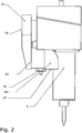
- den Hammer von
Fig. 1 in linker Seitenansicht; - Fig. 3
- eine Schnittdarstellung des Hammers; und
- Fig. 4
- eine perspektivische Untersicht des Hammers.
- Die
Figuren 1 bis 4 zeigen in verschiedenen Darstellungen ein schematisches Beispiel für einen erfindungsgemäßen Bohr- und/oder Schlaghammer. - Der Hammer weist einen Verbrennungsmotor 1 auf, der über einen ersten Kurbeltrieb 2, ein Getriebe 3 und einen zweiten Kurbeltrieb 4 ein Schlagwerk 5 antreibt. Das Schlagwerk 5 wiederum beaufschlagt ein Werkzeug 6, im vorliegenden Beispiel einen Meißel. Der Aufbau eines derartigen Hammers ist vielfältig bekannt und muss daher nicht im Einzelnen erläutert werden.
- Der Verbrennungsmotor 1 weist einen Zylinder 7 auf, in dessen Innerem ein Kolben 8 beweglich geführt wird. Der Kolben 8 treibt über ein Pleuel 9 den ersten Kurbeltrieb 2 an.
- Über eine Kurbelwelle 10 des Kurbeltriebs 2 wird das Getriebe 3 und damit der zweite Kurbeltrieb 4 bewegt.
- Das Schlagwerk 5 ist als Luftfederschlagwerk ausgebildet und weist ein von dem zweiten Kurbeltrieb 4 bewegtes Pleuel 11 auf, das einen Antriebskolben 12 in einem zu dem Schlagwerk gehörenden Führungsgehäuse 13 hin und her bewegt.
- Im Inneren des Antriebskolbens 12 ist ein Schlagkolben 14 geführt, der über eine zwischen dem Antriebskolben 12 und dem Schlagkolben 14 ausgebildete Luftfeder 15 gegen das Ende des Werkzeugs 6 bewegt und wieder zurückgeführt wird. Auch die Funktion eines derartigen Schlagwerks 5 ist bekannt und muss an dieser Stelle nicht näher vertieft werden.
- An dem stirnseitigen Ende der Kurbelwelle 10 ist ein Kühlluftgebläse 16 mit einem Lüfterrad 17, einem Gebläsegehäuse 18 und einem Kühllufteinlass 19 angeordnet. Das Lüfterrad 17 wird durch die Kurbelwelle 10 drehend angetrieben und saugt dabei Umgebungsluft über den Kühllufteinlass 19 an. Die Kühlluft wird dann über einen Kühlluftkanal 20 zu den zu kühlenden Komponenten des Hammers geführt.
- Insbesondere führt der Kühlluftkanal 20 die Kühlluft zu einer Außenwand des Zylinders 7, an der zahlreiche Kühlrippen 21 in bekannter Weise angeordnet sind. In
Figur 3 sind aus Gründen der Übersichtlichkeit nur zwei der Kühlrippen 21 mit dem Bezugszeichen 21 gekennzeichnet. Selbstverständlich weist die Außenwand des Zylinders 7 mehrere Kühlrippen 21 auf, wie auch unmittelbar ausFigur 3 ersichtlich. - Zwischen den Kühlrippen 21 sind jeweilige Teilkanäle 22 ausgebildet, in denen der Luftstrom vom Kühlluftkanal 20 an der Außenwand des Zylinders 7 vorbei geführt werden kann. Jeder dieser Teilkanäle 22 zweigt somit einen Teilkühlluftstrom von dem Haupt-Kühlluftstrom in dem stromauf von dem Zylinder 7 liegenden Kanalbereich des Kühlluftkanals 20 ab.
- Wie in
Figur 3 erkennbar, strömt der Kühlluftstrom im Kühlluftkanal 20 von oben, d. h. vom Kühlluftgebläse 16 kommend in Richtung nach unten, wobei in dem genannten Kanalbereicht nach und nach Teilkühlluftströme über jeweilige Teilkanäle 22 abgezweigt und an der Außenwand des Zylinders 7 vorbeigeführt werden. Dabei verjüngt sich der Kühlluftkanal 20 in dem Maße, wie Kühlluft von ihm in den jeweiligen Teilkanal 22 abgezweigt wird. Dabei soll sich der Querschnitt des Kühlluftkanals 20 derart verringern, dass die Strömungsgeschwindigkeit des Kühlluftstroms in dem stromauf von dem Zylinder 7 vorgesehenen Kühlluftkanal 20 konstant bleibt. InFigur 3 ist diese Verjüngung durch eine schräg verlaufende Kanalabdeckung 23 erkennbar. - Noch besser kann die Querschnittsverjüngung des Kühlluftkanals in
Figur 4 gesehen werden, wo die Kanalabdeckung 23 beginnend an einem Kanaleinlass 24 - bezogen auf eine Betriebsstellung des Hammers mit vertikal nach unten gerichteter Arbeitsrichtung - sowohl in Vertikalrichtung nach unten als auch in Horizontalrichtung, weg von dem Kanaleinlass 24 schräg verläuft und somit den Kühlluftkanal 20 verjüngt. Der Kanaleinlass 24 ist inFigur 4 nur gestrichelt eingezeichnet, da er unter der Kanalabdeckung 23 selbstverständlich nicht von außen sichtbar ist. - Die damit im Kühlluftkanal 20 und in den diversen Teilkanälen 22 bewirkte Kühlluftströmung weist weitgehend eine konstante, gleiche Geschwindigkeit auf, was für eine optimierte Motorkühlung positiv ist.
- Die Kühlluft kann stromab vom Verbrennungsmotor 1, also stromab von der Außenwand des Zylinders 7 an die Umgebung abgeben werden.
- Bei einer besonders vorteilhaften Ausführungsform der Erfindung jedoch - wie sie auch in den Figuren gezeigt ist - wird die vom Motor kommende Kühlluft weiterhin zur Kühlung von sich im Betrieb des Hammers erwärmenden Komponenten genutzt. Insbesondere ist der Kühlluftkanal 20 an einem Auslass 25, an dem die Kühlluft von den Kühlrippen 21 und der Außenwand des Zylinders 7 weggeführt wird, in einen ersten Kühlluftkanal 26 und einen zweiten Kühlluftkanal 27 aufgeteilt. Die Aufteilung erfolgt mit Hilfe von Leitblechen 28 und 29. Die Leitbleche 28, 29 können in geeigneter Weise im Raum geformt sein, um die jeweiligen Kühlluftströme an die zu kühlenden Bereiche zu führen.
- In den ersten Kühlluftkanal 26 wird ein erster Kühlluftstrom geführt und zu einer Abgasanlage 30 des Verbrennungsmotors 1, insbesondere zu einem Schalldämpfer geführt.
- Die Abgasanlage 30 mit dem Schalldämpfer wird im Betrieb des Hammers besonders heiß, so dass die vom Motor kommende Kühlluft, obwohl bereits erwärmt, immer noch zur Kühlung der Abgasanlage 30 beitragen kann. Dadurch wird insbesondere auch erreicht, dass die Abgasanlage 30 nicht ihrerseits andere Komponenten des Hammers, wie z. B. die Kraftstoffzuführung, den Tank oder den Vergaser bei längerem Betrieb des Hammers in unzulässiger Weise erwärmen kann.
- Der zweite Kühlluftkanal 27 führt den zweiten Kühlluftstrom als Kühlluft zu dem Schlagwerk 5, insbesondere an die Außenwand des Führungsgehäuses 13 des Schlagwerks 5 und dort zu einem Bereich des Schlagwerks 5, in dem eine Kompression der Luftfeder 15 stattfindet. Durch die Kompression der Luftfeder 15 wird eine starke Erwärmung im Schlagwerk 5 bewirkt. Diese Wärme kann durch den im zweiten Kühlluftkanal 27 herangeführten zweiten Kühlluftstrom abgeführt werden.
- Darüber hinaus ist es bei geeigneter Gestaltung des Hammers möglich, den zweiten Kühlluftstrom nach Vorbeiströmen an dem Schlagwerk 5 auch noch zur Abgasanlage 30 zuführen, so dass der zweite Kühlluftstrom, der durch das Schlagwerk 5 nur verhältnismäßig gering zusätzlich erwärmt wurde, ebenfalls noch zur Kühlung des heißen Schalldämpfers in der Abgasanlage 30 genutzt werden kann.
- Durch die oben beschriebene Optimierung der Motorluftkühlung durch Vergleichmäßigung der Strömungsgeschwindigkeit ist es möglich, die Temperatur der Motorkühlabluft so weit zu senken, dass sie zur Kühlung von weitern Komponenten des Hammers verwendet werden kann.
- Durch eine gezielte Führung und Verteilung der Motorkühlabluft kann erreicht werden, dass diese nur in Bereiche geführt wird, deren Temperatur so hoch ist, dass sie trotz der bereits relativ warmen Motorkühlabluft noch gekühlt werden können. Beispielsweise kann eine 80°C heiße Motorkühlabluft immer noch den 300°C heißen Schalldämpfer problemlos abkühlen.
- Dadurch, dass die Motorkühlabluft nach Vorbeistreichen an der Außenwand des Zylinders 7 direkt an die weitern heißen Wärmequellen des Hammers geleitet wird und dort kühlend wirkt, werden indirekt auch Bereiche am Hammer weiter abgekühlt, deren Temperatur unterhalb der Motorkühlabluft liegt. Dies wird dadurch erreicht, dass durch eine Kühlung nahe der Wärmequelle weniger Wärme in umgebende Komponenten bzw. Bauteile geleitet wird, so dass diese ebenfalls kühler bleiben.
- Wie in der Beschreibungseinleitung ausführlich beschrieben, ist es auch möglich, den Kühlluftkanal derart auszugestalten, dass die Kühlluft nach Vorbeiströmen an dem Zylinder 7 zunächst zu der Außenwand des Führungsgehäuses 13 und nachfolgend entlang der Abgasanlage 30 geführt wird. Ebenso kann die Kühlluft auch ausschließlich zu der Abgasanlage 30 geleitet werden.
Claims (10)
- Bohr- und/oder Schlaghammer, mit- einem Verbrennungsmotor (1), mit einem Zylinder (7) und einem in dem Zylinder (7) bewegbaren Kolben (8);- einem von dem Verbrennungsmotor (3) angetriebenen Schlagwerk (5);- einem Kühlluftgebläse (16) zum Erzeugen eines Kühlluftstroms; und mit- einem Kühlluftkanal (20) zum Führen des Kühlluftstroms von dem Kühlluftgebläse (16) entlang einer Außenwand des Zylinders (7);dadurch gekennzeichnet, dass- das Schlagwerk (5) von dem Verbrennungsmotor über ein Getriebe (3) angetrieben wird;- der Kühlluftkanal (20) stromab von der Außenwand des Zylinders (7) einen ersten Kanalabschnitt aufweist, zum Führen des Kühlluftstroms zu dem Schlagwerk (5).
- Bohr- und/oder Schlaghammer nach Anspruch 1, dadurch gekennzeichnet, dass- der Kühlluftkanal (20) stromab von dem Schlagwerk (5) einen zweiten Kanalabschnitt aufweist, zum Führen des Kühlluftstroms zu einer Abgasanlage (30) des Verbrennungsmotors (1).
- Bohr- und/oder Schlaghammer nach Anspruch 1 oder 2, dadurch gekennzeichnet, dass- der Kühlluftkanal (20) stromab von der Außenwand des Zylinders (7) aufgeteilt ist in einen ersten Kühlluftkanal (26) für einen ersten Kühlluftstrom und in einen zweiten Kühlluftkanal (27) für einen zweiten Kühlluftstrom;- der erste Kühlluftkanal (26) zum Führen des ersten Kühlluftstroms zu der Abgasanlage (30) des Verbrennungsmotors (1) dient; und dass- der zweite Kühlluftkanal (27) zum Führen des zweiten Kühlluftstroms zu dem Schlagwerk (5) dient.
- Bohr- und/oder Schlaghammer nach Anspruch 3, dadurch gekennzeichnet, dass- das Schlagwerk (5) ein Führungsgehäuse (13) und einen von dem Verbrennungsmotor (1) in dem Führungsgehäuse (13) bewegbaren Antriebskolben (12) aufweist; und dass- der zweite Kühlluftkanal (27) zum Führen des zweiten Kühlluftstroms zu einer Außenseite des Führungsgehäuses (13) dient.
- Bohr- und/oder Schlaghammer nach Anspruch 3 oder 4, dadurch gekennzeichnet, dass der zweite Kühlluftkanal (27) derart ausgebildet ist, dass der zweite Kühlluftstrom stromab von dem Schlagwerk (5) zu der Abgasanlage (30) des Verbrennungsmotors (1) führbar ist.
- Bohr- und/oder Schlaghammer nach einem der Ansprüche 1 bis 5, wobei- stromauf von der Außenwand des Zylinders (7) der Kühlluftkanal (20) einen Kanalbereich aufweist, in dem mehrere Teilkühlluftströme von dem Kühlluftstrom abgezweigt werden; und wobei- der Kanalbereich derart ausgestaltet ist, dass sich der auf eine Strömungsrichtung des Kühlluftstroms bezogene Querschnitt des Kanalbereichs in dem Maße verjüngt, wie Teilkühlluftströme von dem Kühlluftstrom abgezweigt werden, so dass die Strömungsgeschwindigkeit des Kühlluftstroms in dem Kanalbereich im Wesentlichen konstant bleibt.
- Bohr- und/oder Schlaghammer nach Anspruch 6, dadurch gekennzeichnet, dass- an der Außenwand des Zylinders (7) mehrere parallel zueinander verlaufende Kühlrippen (21) ausgebildet sind; und dass- zwischen jeweils zwei zueinander benachbarten Kühlrippen (21) jeweils ein Teilkanal (22) ausgebildet ist, zum Führen eines Teilkühlluftstroms, wobei der Teilkühlluftstrom von dem von dem Kühlluftgebläse (16) herangeführten Kühlluftstrom abgezweigt wird.
- Bohr- und/oder Schlaghammer nach Anspruch 6 oder 7, dadurch gekennzeichnet, dass der Kanalbereich stromauf von den Kühlrippen (21) an den Kühlrippen (21) und damit an den Teilkanälen (22) vorbeiführt und derart ausgestaltet ist, dass sich der Querschnitt des Kanalbereichs in dessen Verlauf entlang der Anfangsbereiche der jeweiligen Teilkanäle in dem Maße verjüngt, wie Teilkühlluftströme von dem Kühlluftstrom abgezweigt werden, so dass die Strömungsgeschwindigkeit des Kühlluftstroms in dem Kanalbereich im Wesentlichen konstant bleibt.
- Bohr- und/oder Schlaghammer nach einem der Ansprüche 6 bis 8, dadurch gekennzeichnet, dass die Strömungsgeschwindigkeiten der Teilkühlluftströme in den Teilkanälen (22) im Wesentlichen gleich sind.
- Bohr- und/oder Schlaghammer nach einem der Ansprüche 6 bis 9, dadurch gekennzeichnet, dass das Kühlluftgebläse (16) durch eine Kurbelwelle (10) des Verbrennungsmotors (1) angetrieben wird.
Applications Claiming Priority (2)
| Application Number | Priority Date | Filing Date | Title |
|---|---|---|---|
| DE102010004724A DE102010004724A1 (de) | 2010-01-15 | 2010-01-15 | Bohr- und/oder Schlaghammer mit Kühlung von Gerätekomponenten |
| PCT/EP2011/000134 WO2011085989A1 (de) | 2010-01-15 | 2011-01-13 | Bohr- und/oder schlaghammer mit kühlung von gerätekomponenten |
Publications (2)
| Publication Number | Publication Date |
|---|---|
| EP2523780A1 EP2523780A1 (de) | 2012-11-21 |
| EP2523780B1 true EP2523780B1 (de) | 2020-03-04 |
Family
ID=43662075
Family Applications (1)
| Application Number | Title | Priority Date | Filing Date |
|---|---|---|---|
| EP11700320.2A Active EP2523780B1 (de) | 2010-01-15 | 2011-01-13 | Bohr- und/oder schlaghammer mit kühlung von gerätekomponenten |
Country Status (5)
| Country | Link |
|---|---|
| US (1) | US9272407B2 (de) |
| EP (1) | EP2523780B1 (de) |
| CN (1) | CN102770245B (de) |
| DE (1) | DE102010004724A1 (de) |
| WO (1) | WO2011085989A1 (de) |
Families Citing this family (4)
| Publication number | Priority date | Publication date | Assignee | Title |
|---|---|---|---|---|
| GB201413008D0 (en) | 2014-07-23 | 2014-09-03 | Black & Decker Inc | A range of power tools |
| CN106012787B (zh) * | 2016-05-31 | 2017-12-19 | 福州麦辽自动化设备有限公司 | 一种基于液压阀控制的钎杆触发破碎锤 |
| US10710923B2 (en) * | 2017-10-26 | 2020-07-14 | Wuhan China Star Optoelectronics Semiconductor Display Technology Co., Ltd. | Wheel cutter for cutting a flexible glass substrate and cutting method thereof |
| CN108890374A (zh) * | 2018-07-22 | 2018-11-27 | 苏州优康通信设备有限公司 | 一种通信器材的钻孔设备 |
Citations (1)
| Publication number | Priority date | Publication date | Assignee | Title |
|---|---|---|---|---|
| GB632560A (en) * | 1944-07-13 | 1949-11-28 | Carl Stanley Weyandt | Improvements in or relating to a percussion tool |
Family Cites Families (14)
| Publication number | Priority date | Publication date | Assignee | Title |
|---|---|---|---|---|
| DE866633C (de) * | 1950-04-29 | 1953-02-12 | Gustav Albert Bergman | Anordnung an Verbrennungsmotoren, insbesondere fuer Gesteinsbohrmaschinen |
| US2764138A (en) * | 1953-03-02 | 1956-09-25 | Atlas Copco Ab | Percussion tools having a reciprocable hammer piston actuated by combustion gases |
| US2857888A (en) * | 1957-05-17 | 1958-10-28 | Syntron Co | Portable internal combustion percussion tools |
| DE2016964B2 (de) * | 1970-04-09 | 1977-09-15 | Robert Bosch Gmbh, 7000 Stuttgart | Von hand gefuehrter hammer mit eingebautem elektrischen antriebsmotor |
| US3718193A (en) * | 1971-02-18 | 1973-02-27 | Bosch Gmbh Robert | Cooling system for portable impulse transmitting machines |
| JPS48111601U (de) * | 1972-03-31 | 1973-12-21 | ||
| US4094365A (en) * | 1974-05-20 | 1978-06-13 | Robert Bosch Gmbh | Electrohydraulically operated portable power tool |
| DE2835570C2 (de) * | 1978-08-14 | 1987-01-29 | Hilti Ag, Schaan | Bohr- und Meisselhammer mit Verbrennungsmotorantrieb |
| JP2000052277A (ja) * | 1998-08-12 | 2000-02-22 | Hitachi Koki Co Ltd | 打撃工具 |
| JP2000153473A (ja) * | 1998-11-19 | 2000-06-06 | Makita Corp | 打撃工具 |
| EP1302281B1 (de) * | 2001-10-15 | 2007-05-02 | HILTI Aktiengesellschaft | Kühlluftleitung für ein Elektrohandwerkzeuggerät mit elektropneumatischem Schlagwerk |
| CN2688454Y (zh) * | 2004-03-25 | 2005-03-30 | 苏州宝时得电动工具有限公司 | 电动工具的冷却结构 |
| DE102004058696A1 (de) * | 2004-12-06 | 2006-06-08 | Hilti Ag | Elektrowerkzeuggerät |
| DE102005036560A1 (de) * | 2005-08-03 | 2007-02-08 | Wacker Construction Equipment Ag | Bohr- und/oder Schlaghammer mit Linearantrieb und Luftkühlung |
-
2010
- 2010-01-15 DE DE102010004724A patent/DE102010004724A1/de not_active Ceased
-
2011
- 2011-01-13 WO PCT/EP2011/000134 patent/WO2011085989A1/de not_active Ceased
- 2011-01-13 US US13/521,077 patent/US9272407B2/en not_active Expired - Fee Related
- 2011-01-13 EP EP11700320.2A patent/EP2523780B1/de active Active
- 2011-01-13 CN CN201180005736.2A patent/CN102770245B/zh active Active
Patent Citations (1)
| Publication number | Priority date | Publication date | Assignee | Title |
|---|---|---|---|---|
| GB632560A (en) * | 1944-07-13 | 1949-11-28 | Carl Stanley Weyandt | Improvements in or relating to a percussion tool |
Also Published As
| Publication number | Publication date |
|---|---|
| US9272407B2 (en) | 2016-03-01 |
| CN102770245B (zh) | 2016-01-20 |
| CN102770245A (zh) | 2012-11-07 |
| US20130098650A1 (en) | 2013-04-25 |
| WO2011085989A1 (de) | 2011-07-21 |
| EP2523780A1 (de) | 2012-11-21 |
| DE102010004724A1 (de) | 2011-07-21 |
Similar Documents
| Publication | Publication Date | Title |
|---|---|---|
| EP1666213B1 (de) | Elektrowerkzeuggerät | |
| DE2441045A1 (de) | Schalldaemmgehaeuse fuer maschinenaggregate mit kuehler | |
| DE112005001444T5 (de) | Kombinierter Auspuffdämpfer/Wärmetauscher | |
| DE102008037934B4 (de) | Maschine mit Kühlsystem und Verfahren dafür | |
| DE102016012796B4 (de) | Fahrzeug mit Fahrsattel | |
| EP4174233A1 (de) | Elektrische arbeitsmaschine mit akkukühlung | |
| EP2523780A1 (de) | Bohr- und/oder schlaghammer mit kühlung von gerätekomponenten | |
| DE3217064A1 (de) | Ansaugleitungskonstruktion fuer brennkraftmaschinen | |
| EP1503033A1 (de) | Gerät zur Erzeugung eines Luftstromes in schallgedämmter Ausführung für Entstauber | |
| DE2757966A1 (de) | Luftfuehrung fuer ein kraftfahrzeug | |
| DE102019220259A1 (de) | Drehwärmetauscher und dazugehöriges system | |
| DE102005007546A1 (de) | Elektrowerkzeugmaschine | |
| DE102015204984A1 (de) | Wärmetauscher, insbesondere für eine Abwärmenutzungseinrichtung | |
| EP3567309B1 (de) | Luftansaugvorrichtung für ein mit einer brennkraftmaschine ausgestattetes fahrzeug | |
| DE29914164U1 (de) | Motorbetriebenes Handwerkzeug | |
| DE4339936A1 (de) | Anordnung eines Wärmetauschers im Unterbodenbereich eines Fahrzeuges | |
| DE102014207347B4 (de) | Anordnung zur Führung von Kühlluft in einem Kraftfahrzeug | |
| DE102012010681B4 (de) | Anordnung zur Temperierung des Schmiermittels einer Brennkraftmaschine | |
| DE102014208259A1 (de) | Kühleinrichtung zur Kühlung eines fluiden Mediums, Abgasrückführsystem für eine Brennkraftmaschine und Brennkraftmaschine | |
| DE102011050323B3 (de) | Kühlvorrichtung zur Klimatisierung einer Datenverarbeitungsanlage | |
| EP2006508A2 (de) | Versorgungseinheit mit einem Motor-Generator-Aggregat als Stromerzeuger | |
| DE1590143C3 (de) | ölgefülltes, gekühltes Hochspannungskabel | |
| DE102005001959A1 (de) | Kühlluftführung eines in einem Motorraum angeordneten Verbrennungsmotors einer Sattelzugmaschine | |
| DE2935589A1 (de) | Fahrzeugantrieb | |
| DE102008038373A1 (de) | Anordnung eines Abschirmblechs |
Legal Events
| Date | Code | Title | Description |
|---|---|---|---|
| PUAI | Public reference made under article 153(3) epc to a published international application that has entered the european phase |
Free format text: ORIGINAL CODE: 0009012 |
|
| 17P | Request for examination filed |
Effective date: 20120621 |
|
| AK | Designated contracting states |
Kind code of ref document: A1 Designated state(s): AL AT BE BG CH CY CZ DE DK EE ES FI FR GB GR HR HU IE IS IT LI LT LU LV MC MK MT NL NO PL PT RO RS SE SI SK SM TR |
|
| DAX | Request for extension of the european patent (deleted) | ||
| 17Q | First examination report despatched |
Effective date: 20150401 |
|
| STAA | Information on the status of an ep patent application or granted ep patent |
Free format text: STATUS: EXAMINATION IS IN PROGRESS |
|
| GRAP | Despatch of communication of intention to grant a patent |
Free format text: ORIGINAL CODE: EPIDOSNIGR1 |
|
| STAA | Information on the status of an ep patent application or granted ep patent |
Free format text: STATUS: GRANT OF PATENT IS INTENDED |
|
| INTG | Intention to grant announced |
Effective date: 20191016 |
|
| GRAS | Grant fee paid |
Free format text: ORIGINAL CODE: EPIDOSNIGR3 |
|
| GRAA | (expected) grant |
Free format text: ORIGINAL CODE: 0009210 |
|
| STAA | Information on the status of an ep patent application or granted ep patent |
Free format text: STATUS: THE PATENT HAS BEEN GRANTED |
|
| AK | Designated contracting states |
Kind code of ref document: B1 Designated state(s): AL AT BE BG CH CY CZ DE DK EE ES FI FR GB GR HR HU IE IS IT LI LT LU LV MC MK MT NL NO PL PT RO RS SE SI SK SM TR |
|
| REG | Reference to a national code |
Ref country code: GB Ref legal event code: FG4D Free format text: NOT ENGLISH |
|
| REG | Reference to a national code |
Ref country code: CH Ref legal event code: EP |
|
| REG | Reference to a national code |
Ref country code: AT Ref legal event code: REF Ref document number: 1239844 Country of ref document: AT Kind code of ref document: T Effective date: 20200315 |
|
| REG | Reference to a national code |
Ref country code: DE Ref legal event code: R096 Ref document number: 502011016516 Country of ref document: DE |
|
| REG | Reference to a national code |
Ref country code: IE Ref legal event code: FG4D Free format text: LANGUAGE OF EP DOCUMENT: GERMAN |
|
| REG | Reference to a national code |
Ref country code: SE Ref legal event code: TRGR |
|
| PG25 | Lapsed in a contracting state [announced via postgrant information from national office to epo] |
Ref country code: RS Free format text: LAPSE BECAUSE OF FAILURE TO SUBMIT A TRANSLATION OF THE DESCRIPTION OR TO PAY THE FEE WITHIN THE PRESCRIBED TIME-LIMIT Effective date: 20200304 Ref country code: NO Free format text: LAPSE BECAUSE OF FAILURE TO SUBMIT A TRANSLATION OF THE DESCRIPTION OR TO PAY THE FEE WITHIN THE PRESCRIBED TIME-LIMIT Effective date: 20200604 Ref country code: FI Free format text: LAPSE BECAUSE OF FAILURE TO SUBMIT A TRANSLATION OF THE DESCRIPTION OR TO PAY THE FEE WITHIN THE PRESCRIBED TIME-LIMIT Effective date: 20200304 |
|
| REG | Reference to a national code |
Ref country code: NL Ref legal event code: MP Effective date: 20200304 |
|
| PG25 | Lapsed in a contracting state [announced via postgrant information from national office to epo] |
Ref country code: HR Free format text: LAPSE BECAUSE OF FAILURE TO SUBMIT A TRANSLATION OF THE DESCRIPTION OR TO PAY THE FEE WITHIN THE PRESCRIBED TIME-LIMIT Effective date: 20200304 Ref country code: LV Free format text: LAPSE BECAUSE OF FAILURE TO SUBMIT A TRANSLATION OF THE DESCRIPTION OR TO PAY THE FEE WITHIN THE PRESCRIBED TIME-LIMIT Effective date: 20200304 Ref country code: GR Free format text: LAPSE BECAUSE OF FAILURE TO SUBMIT A TRANSLATION OF THE DESCRIPTION OR TO PAY THE FEE WITHIN THE PRESCRIBED TIME-LIMIT Effective date: 20200605 Ref country code: BG Free format text: LAPSE BECAUSE OF FAILURE TO SUBMIT A TRANSLATION OF THE DESCRIPTION OR TO PAY THE FEE WITHIN THE PRESCRIBED TIME-LIMIT Effective date: 20200604 |
|
| REG | Reference to a national code |
Ref country code: LT Ref legal event code: MG4D |
|
| PG25 | Lapsed in a contracting state [announced via postgrant information from national office to epo] |
Ref country code: NL Free format text: LAPSE BECAUSE OF FAILURE TO SUBMIT A TRANSLATION OF THE DESCRIPTION OR TO PAY THE FEE WITHIN THE PRESCRIBED TIME-LIMIT Effective date: 20200304 |
|
| PG25 | Lapsed in a contracting state [announced via postgrant information from national office to epo] |
Ref country code: EE Free format text: LAPSE BECAUSE OF FAILURE TO SUBMIT A TRANSLATION OF THE DESCRIPTION OR TO PAY THE FEE WITHIN THE PRESCRIBED TIME-LIMIT Effective date: 20200304 Ref country code: PT Free format text: LAPSE BECAUSE OF FAILURE TO SUBMIT A TRANSLATION OF THE DESCRIPTION OR TO PAY THE FEE WITHIN THE PRESCRIBED TIME-LIMIT Effective date: 20200729 Ref country code: SM Free format text: LAPSE BECAUSE OF FAILURE TO SUBMIT A TRANSLATION OF THE DESCRIPTION OR TO PAY THE FEE WITHIN THE PRESCRIBED TIME-LIMIT Effective date: 20200304 Ref country code: RO Free format text: LAPSE BECAUSE OF FAILURE TO SUBMIT A TRANSLATION OF THE DESCRIPTION OR TO PAY THE FEE WITHIN THE PRESCRIBED TIME-LIMIT Effective date: 20200304 Ref country code: CZ Free format text: LAPSE BECAUSE OF FAILURE TO SUBMIT A TRANSLATION OF THE DESCRIPTION OR TO PAY THE FEE WITHIN THE PRESCRIBED TIME-LIMIT Effective date: 20200304 Ref country code: SK Free format text: LAPSE BECAUSE OF FAILURE TO SUBMIT A TRANSLATION OF THE DESCRIPTION OR TO PAY THE FEE WITHIN THE PRESCRIBED TIME-LIMIT Effective date: 20200304 Ref country code: IS Free format text: LAPSE BECAUSE OF FAILURE TO SUBMIT A TRANSLATION OF THE DESCRIPTION OR TO PAY THE FEE WITHIN THE PRESCRIBED TIME-LIMIT Effective date: 20200704 Ref country code: ES Free format text: LAPSE BECAUSE OF FAILURE TO SUBMIT A TRANSLATION OF THE DESCRIPTION OR TO PAY THE FEE WITHIN THE PRESCRIBED TIME-LIMIT Effective date: 20200304 Ref country code: LT Free format text: LAPSE BECAUSE OF FAILURE TO SUBMIT A TRANSLATION OF THE DESCRIPTION OR TO PAY THE FEE WITHIN THE PRESCRIBED TIME-LIMIT Effective date: 20200304 |
|
| REG | Reference to a national code |
Ref country code: DE Ref legal event code: R097 Ref document number: 502011016516 Country of ref document: DE |
|
| PLBE | No opposition filed within time limit |
Free format text: ORIGINAL CODE: 0009261 |
|
| STAA | Information on the status of an ep patent application or granted ep patent |
Free format text: STATUS: NO OPPOSITION FILED WITHIN TIME LIMIT |
|
| PG25 | Lapsed in a contracting state [announced via postgrant information from national office to epo] |
Ref country code: DK Free format text: LAPSE BECAUSE OF FAILURE TO SUBMIT A TRANSLATION OF THE DESCRIPTION OR TO PAY THE FEE WITHIN THE PRESCRIBED TIME-LIMIT Effective date: 20200304 Ref country code: IT Free format text: LAPSE BECAUSE OF FAILURE TO SUBMIT A TRANSLATION OF THE DESCRIPTION OR TO PAY THE FEE WITHIN THE PRESCRIBED TIME-LIMIT Effective date: 20200304 |
|
| 26N | No opposition filed |
Effective date: 20201207 |
|
| PG25 | Lapsed in a contracting state [announced via postgrant information from national office to epo] |
Ref country code: PL Free format text: LAPSE BECAUSE OF FAILURE TO SUBMIT A TRANSLATION OF THE DESCRIPTION OR TO PAY THE FEE WITHIN THE PRESCRIBED TIME-LIMIT Effective date: 20200304 Ref country code: SI Free format text: LAPSE BECAUSE OF FAILURE TO SUBMIT A TRANSLATION OF THE DESCRIPTION OR TO PAY THE FEE WITHIN THE PRESCRIBED TIME-LIMIT Effective date: 20200304 |
|
| PGFP | Annual fee paid to national office [announced via postgrant information from national office to epo] |
Ref country code: GB Payment date: 20210122 Year of fee payment: 11 |
|
| PG25 | Lapsed in a contracting state [announced via postgrant information from national office to epo] |
Ref country code: MC Free format text: LAPSE BECAUSE OF FAILURE TO SUBMIT A TRANSLATION OF THE DESCRIPTION OR TO PAY THE FEE WITHIN THE PRESCRIBED TIME-LIMIT Effective date: 20200304 |
|
| REG | Reference to a national code |
Ref country code: CH Ref legal event code: PL |
|
| PG25 | Lapsed in a contracting state [announced via postgrant information from national office to epo] |
Ref country code: LU Free format text: LAPSE BECAUSE OF NON-PAYMENT OF DUE FEES Effective date: 20210113 |
|
| REG | Reference to a national code |
Ref country code: BE Ref legal event code: MM Effective date: 20210131 |
|
| PG25 | Lapsed in a contracting state [announced via postgrant information from national office to epo] |
Ref country code: FR Free format text: LAPSE BECAUSE OF NON-PAYMENT OF DUE FEES Effective date: 20210131 |
|
| PG25 | Lapsed in a contracting state [announced via postgrant information from national office to epo] |
Ref country code: LI Free format text: LAPSE BECAUSE OF NON-PAYMENT OF DUE FEES Effective date: 20210131 Ref country code: CH Free format text: LAPSE BECAUSE OF NON-PAYMENT OF DUE FEES Effective date: 20210131 |
|
| PG25 | Lapsed in a contracting state [announced via postgrant information from national office to epo] |
Ref country code: IE Free format text: LAPSE BECAUSE OF NON-PAYMENT OF DUE FEES Effective date: 20210113 |
|
| REG | Reference to a national code |
Ref country code: AT Ref legal event code: MM01 Ref document number: 1239844 Country of ref document: AT Kind code of ref document: T Effective date: 20210113 |
|
| PG25 | Lapsed in a contracting state [announced via postgrant information from national office to epo] |
Ref country code: AT Free format text: LAPSE BECAUSE OF NON-PAYMENT OF DUE FEES Effective date: 20210113 |
|
| PG25 | Lapsed in a contracting state [announced via postgrant information from national office to epo] |
Ref country code: BE Free format text: LAPSE BECAUSE OF NON-PAYMENT OF DUE FEES Effective date: 20210131 |
|
| GBPC | Gb: european patent ceased through non-payment of renewal fee |
Effective date: 20220113 |
|
| PG25 | Lapsed in a contracting state [announced via postgrant information from national office to epo] |
Ref country code: GB Free format text: LAPSE BECAUSE OF NON-PAYMENT OF DUE FEES Effective date: 20220113 |
|
| PG25 | Lapsed in a contracting state [announced via postgrant information from national office to epo] |
Ref country code: HU Free format text: LAPSE BECAUSE OF FAILURE TO SUBMIT A TRANSLATION OF THE DESCRIPTION OR TO PAY THE FEE WITHIN THE PRESCRIBED TIME-LIMIT; INVALID AB INITIO Effective date: 20110113 Ref country code: CY Free format text: LAPSE BECAUSE OF FAILURE TO SUBMIT A TRANSLATION OF THE DESCRIPTION OR TO PAY THE FEE WITHIN THE PRESCRIBED TIME-LIMIT Effective date: 20200304 |
|
| PG25 | Lapsed in a contracting state [announced via postgrant information from national office to epo] |
Ref country code: MK Free format text: LAPSE BECAUSE OF FAILURE TO SUBMIT A TRANSLATION OF THE DESCRIPTION OR TO PAY THE FEE WITHIN THE PRESCRIBED TIME-LIMIT Effective date: 20200304 |
|
| PG25 | Lapsed in a contracting state [announced via postgrant information from national office to epo] |
Ref country code: TR Free format text: LAPSE BECAUSE OF FAILURE TO SUBMIT A TRANSLATION OF THE DESCRIPTION OR TO PAY THE FEE WITHIN THE PRESCRIBED TIME-LIMIT Effective date: 20200304 |
|
| PG25 | Lapsed in a contracting state [announced via postgrant information from national office to epo] |
Ref country code: MT Free format text: LAPSE BECAUSE OF FAILURE TO SUBMIT A TRANSLATION OF THE DESCRIPTION OR TO PAY THE FEE WITHIN THE PRESCRIBED TIME-LIMIT Effective date: 20200304 |
|
| PGFP | Annual fee paid to national office [announced via postgrant information from national office to epo] |
Ref country code: SE Payment date: 20250122 Year of fee payment: 15 |
|
| PGFP | Annual fee paid to national office [announced via postgrant information from national office to epo] |
Ref country code: DE Payment date: 20260120 Year of fee payment: 16 |