EP2522202B1 - Produktionsmaschine mit einer betriebszustandswarnleuchtvorrichtung - Google Patents
Produktionsmaschine mit einer betriebszustandswarnleuchtvorrichtung Download PDFInfo
- Publication number
- EP2522202B1 EP2522202B1 EP11740567.0A EP11740567A EP2522202B1 EP 2522202 B1 EP2522202 B1 EP 2522202B1 EP 11740567 A EP11740567 A EP 11740567A EP 2522202 B1 EP2522202 B1 EP 2522202B1
- Authority
- EP
- European Patent Office
- Prior art keywords
- warning light
- electrode
- production machine
- warning
- light element
- Prior art date
- Legal status (The legal status is an assumption and is not a legal conclusion. Google has not performed a legal analysis and makes no representation as to the accuracy of the status listed.)
- Active
Links
Images
Classifications
-
- H—ELECTRICITY
- H05—ELECTRIC TECHNIQUES NOT OTHERWISE PROVIDED FOR
- H05B—ELECTRIC HEATING; ELECTRIC LIGHT SOURCES NOT OTHERWISE PROVIDED FOR; CIRCUIT ARRANGEMENTS FOR ELECTRIC LIGHT SOURCES, IN GENERAL
- H05B33/00—Electroluminescent light sources
- H05B33/12—Light sources with substantially two-dimensional radiating surfaces
-
- F—MECHANICAL ENGINEERING; LIGHTING; HEATING; WEAPONS; BLASTING
- F21—LIGHTING
- F21S—NON-PORTABLE LIGHTING DEVICES; SYSTEMS THEREOF; VEHICLE LIGHTING DEVICES SPECIALLY ADAPTED FOR VEHICLE EXTERIORS
- F21S8/00—Lighting devices intended for fixed installation
-
- G—PHYSICS
- G08—SIGNALLING
- G08B—SIGNALLING OR CALLING SYSTEMS; ORDER TELEGRAPHS; ALARM SYSTEMS
- G08B5/00—Visible signalling systems, e.g. personal calling systems, remote indication of seats occupied
- G08B5/22—Visible signalling systems, e.g. personal calling systems, remote indication of seats occupied using electric transmission; using electromagnetic transmission
- G08B5/36—Visible signalling systems, e.g. personal calling systems, remote indication of seats occupied using electric transmission; using electromagnetic transmission using visible light sources
Definitions
- the invention relates to a production machine, in particular a machine tool or the like, with a machine housing for at least partially wrapping the production machine and with a Radioswarnleuchtvorraum for visual display of at least one operating condition, in particular of several different operating conditions, of a technical device such as a machine, a plant or The like with at least one designed as a light-emitting diode and a warning light having warning light element according to the preamble of claim 1.
- signal towers as Radioswarnleuchtvoriques for displaying, for example, operating conditions of production machines such as machine tools, flow or conveyor belts, soldering or welding machines / robots, printing or labeling machines, painting or washing units, baking or cooking units, injection molding machines or the like in use.
- production machines such as machine tools, flow or conveyor belts, soldering or welding machines / robots, printing or labeling machines, painting or washing units, baking or cooking units, injection molding machines or the like in use.
- exchange modules so that the operator or others can easily recognize the proper state or a fault or danger.
- a signaling column or signal light which has no change modules, but a cylindrical warning light matrix with numerous, arranged like a matrix luminous dots.
- the cylinder is thus constructed as a so-called matrix display, which is to be realized with LEDs or organic LEDs (OLED).
- LEDs or organic LEDs OLED
- this signal tower can, on the one hand, be monochromatic or it is also possible to display multicolored luminous images, such as letters, characters or figures, due to the use of differently colored LEDs or OLEDs.
- the dotted or "restless” luminous area is disadvantageous for the perception of the optical warning signal.
- the warning signal of the signal devices or signal towers is sometimes something "lost" and may possibly be overlooked by the staff.
- the individual warning signal can be overlooked or confused even in larger production halls with several, each having at least one signal device having production machines. Often there is also a certain noise level in such halls, so that even additional, acoustic warning signals of the signal devices are difficult to perceive or in part also overheard.
- a signal tower with a luminous cylinder jacket known.
- the jacket has a DLED matrix, inter alia for signaling and, if appropriate, image representation.
- the object of the invention is to propose a production machine with a Radioswarnleuchtvorraum for visual display of at least one operating state of the production machine, with a better visibility than in the prior art is achieved.
- a production machine is characterized in that the machine housing comprises at least the warning light element and that the electrode surfaces of the electrodes substantially correspond to the warning light surface of the warning light element and that at least one of the electrodes is translucent and / or transparent and that at least a part of the machine housing as a carrier layer the warning light element is formed.
- the production machine is formed for RadioSsWarnleuchtvortechnische.
- a separate signal tower or the like is thereby unnecessary.
- warning light can be formed. Accordingly, according to the invention, a particularly large-sized or large-area warning light area can be realized. This warning lights can be realized per warning color, which is a multiple of the usual signal towers. Significantly improved perceptibility is achieved.
- a homogeneous warning light area is realized, which is more homogeneous in contrast to the matrix light areas or from numerous individual light points or light emitting diodes composed total Warrleucht Structure.
- the warning light-emitting surface is understood to mean the surface of the warning light-emitting element, through which the warning light exits the warning light element in the environment or the air.
- electrodes are provided whose electrode surfaces correspond in each case essentially to the entire warning light-emitting surface of the warning light-emitting element, which simplifies their manufacture. Due to the translucent or transparent design of one of the electrodes, it is possible to arrange them on the outside or surface of the warning light element, so that advantageously the light of the LED can penetrate through these to the outside or to the surface, so this according to the operator or otherwise perceptible.
- an arrangement of the electrodes or the luminescent layer of the light-emitting diode transversely to the emission direction of the warning light or substantially parallel to the surface or to the warning light surface is advantageous. Accordingly, an inventive construction with individual layers, which are preferably arranged substantially parallel to each other, wherein a luminescent layer disposed between two electrode layers and one of the electrodes is translucent and / or transparent.
- the electrodes are arranged in an ordinary LED for the matrix-shaped arrangement substantially in the direction of the emission direction of the warning light, between which lies the luminous region of the light-emitting diode. That is, the electrodes are juxtaposed in an ordinary LED, and not superimposed as in the present invention.
- the first and second electrodes are translucent and / or transparent.
- the entire light-emitting diode according to the invention in the off or in the non-luminous state is largely or almost invisible. This results in completely novel possibilities of arrangement of the warning light element according to the invention.
- the perceptibility of the warning light is thereby improved, since the warning light almost comes from nowhere, so that a surprise effect is achieved even with the operator or with appropriate people, which further improves the visibility or signaling.
- the almost invisible in the off state warning light element can also be arranged in an advantageous manner on transparent or transparent surfaces.
- the warning light element according to the invention can be arranged on a viewing window of the production or machine tool, through which the machinist observes, for example, the workpiece or tool machining. In the event of a warning, this invisible warning light element according to the invention can then light up red, for example, so that a high warning effect or great perceptibility is achieved.
- the warning light element has at least one second luminescent layer arranged between the second electrode and a third electrode, the electrode surface of the third electrode essentially corresponding to the warning luminescent surface of the warning luminescent element.
- a multi-color can be realized, in which the luminous layer is subjected to different voltage and / or electrical current.
- the light of the lower luminescent layer can also radiate through the overlying electrodes or luminescent layers or penetrate them.
- the luminous regions are not arranged side by side, as in a matrix-type arrangement of differently colored LEDs, but are arranged one above the other.
- the electrodes and the luminescent layers are arranged substantially parallel to one another or to the warning luminescent surface.
- a layer structure of electrodes and luminescent layers is provided.
- the outwardly directed or directed towards the surface electrodes or luminescent layers are advantageously transparent or translucent. If appropriate, only the innermost electrode can not be made transparent.
- a transparent warning light element is realized which, as already mentioned above, is almost invisible or not perceived in the switched-off or non-luminous state.
- a tricolor warning light in the case of a tricolor warning light, three different luminescent layers can be provided between in each case two, possibly partially identical electrodes.
- a combination of the colors can be realized by the simultaneous driving of two or more different luminescent layers, so that any or innumerable hues can be generated.
- this color variation or color combination can be generated by, for example, three different luminescent layers arranged one above the other.
- the warning light area and / or the electrode surface is at least 1 m 2 , in particular several square meters in size.
- This large-scale design of the warning light a particularly high visibility is achieved.
- 2 m 2 large warning lights or even larger warning lights according to the invention are quite feasible.
- a particularly good perceptibility of the operating state to be displayed is achieved. This clearly exceeds previous dimensions of signal towers or the like.
- one side of the machine housing such. B. a front, substantially completely formed as RadioSwarnleuchtvortechnisch according to the invention.
- a planar or flat surface of the machine housing can be provided here as an operating state warning light device.
- a three-dimensional surface or a structured, bent or angular machine housing surface can definitely also be designed as an operating state warning lighting device according to the invention.
- a window of the machine housing is designed as an operating state warning light device according to the invention. It is particularly advantageous if the bioShwarnleuchtvortechnisch is almost completely transparent or translucent in the non-illuminated or off state.
- the warning light element may have any shapes and / or is advantageously flexible, so that this to any shape, for example, the machine housing of the production machine such. B. a machine tool can be adjusted.
- the operating state warning light device or the warning light element is fixed to the machine housing, for example glued to the machine housing or formed as a coating of the machine housing.
- the warning light element or the various layers of the warning light element such as electrodes and / or luminescent layers, by advantageous spraying and / or vapor deposition and / or applied as paints or the like at advantageous locations or on advantageous areas of a machine housing.
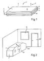
- warning light element 1 according to the invention is shown schematically.
- warning light 2 is emitted by a warning light surface 3 which is emitted by a luminescent layer 4 of an organic light-emitting diode (OLED).
- OLED organic light-emitting diode
- Two electrodes 5 and 6 are arranged on both sides of the luminescent layer 4 and each have an electrode surface which corresponds to the warning luminescent surface 3.
- the luminescent layer 4 is arranged between a first and a second electrode 5, 6.
- the electrodes 5, 6 are subjected to an electric current / voltage. This is represented symbolically by an electrical current or voltage supply 7.
- the cover layer 9 can also be provided as a protective layer or as a seal in order to protect the partially sensitive luminescent layers 4 of an OLED.
- the base layer 8 is arranged or fixed on a machine housing or the base layer 8 is formed as the machine housing.
- the base layer 8 can be formed as a mechanically stable or supporting carrier or support layer, which can also take over the machine housing in the corresponding variant set out above.
- the machine housing is additionally designed as a carrier or support layer. Accordingly, the design and manufacturing costs are reduced by the dual function of the machine housing according to the invention.
- other layers such as. B. optionally between the luminescent layer 4 and an electrode 5 or 6, a non-illustrated, but optionally be provided electrically conductive intermediate layer can be provided.
- the individual layers 4, 5, 6, 8, 9 flexible, for example, so that a flexible warning light element 1 designed as a foil or the like can be realized.
- This can for example be adapted to any geometric shapes or areas.
- the warning light or the warning light element 1 can also be adapted to angled, curved or structured or three-dimensionally formed machine housing and / or glued or attached.
- FIG. 2 schematically a production room with a door 10 and a window 11 and with a production machine 12 is shown, for example, has a machine housing 13 having a plurality of individual housing sides. Exemplary are in FIG. 2 formed two individual surfaces of the machine housing 13 as warning lights 1 according to the invention.
- a window 14 of the machine housing 13 can likewise be formed as a warning light or warning light element 1 according to the invention.
- this viewing window 14 for example, an operator can observe the production or the workpiece machining.
- the viewing window 14 can advantageously light up in color and / or flash.
- a part eg only one of the warning lights 1 of the machine housing 13 lights up when the magazine is empty.
- several or even all the warning lights 1 of the production machine 12 turn red.
- a particularly high degree of perceptibility of corresponding operating states and / or dangerous states is achieved. This means a much higher visibility as previously possible by means of signal towers or the like, which were attached or fixed for example on the housing 13 of the production machine 12 above.
- the warning lights or warning light elements 1 can be glued or applied to existing surfaces of the machine housing 13, such as front sides, housing doors, windows 14 or the like, for example as a film. In this case, the machine housing 13 would be separate from the base layer 8 of the warning light element 1.
- the various layers 4, 5, 6, 8, 9 of the warning light 1 according to the invention can also be applied by means of a wide variety of application methods even during the production of corresponding components of the machine housing.
- spraying, printing and / or vapor deposition processes can be provided for this purpose.
- a top-coat method or a painting process can be provided.
- the machine housing 13 could be formed as the base layer 8 of the warning light element 1.
- large-area warning lights can be mounted on other surfaces of the production room or a production building preferably and / or warning lights can be provided with a matrix structure, for example, textual information , Characters, pictures or the like in addition to display.
Landscapes
- Engineering & Computer Science (AREA)
- General Engineering & Computer Science (AREA)
- Illuminated Signs And Luminous Advertising (AREA)
- Machine Tool Units (AREA)
- Electroluminescent Light Sources (AREA)
- Machine Tool Sensing Apparatuses (AREA)
Applications Claiming Priority (2)
| Application Number | Priority Date | Filing Date | Title |
|---|---|---|---|
| DE102010033939 | 2010-08-10 | ||
| PCT/EP2011/003751 WO2012019705A1 (de) | 2010-08-10 | 2011-07-27 | Produktionsmaschine mit einer betriebszustandswarnleuchtvorrichtung |
Publications (2)
| Publication Number | Publication Date |
|---|---|
| EP2522202A1 EP2522202A1 (de) | 2012-11-14 |
| EP2522202B1 true EP2522202B1 (de) | 2014-06-18 |
Family
ID=44629627
Family Applications (1)
| Application Number | Title | Priority Date | Filing Date |
|---|---|---|---|
| EP11740567.0A Active EP2522202B1 (de) | 2010-08-10 | 2011-07-27 | Produktionsmaschine mit einer betriebszustandswarnleuchtvorrichtung |
Country Status (6)
| Country | Link |
|---|---|
| US (1) | US9041279B2 (enExample) |
| EP (1) | EP2522202B1 (enExample) |
| JP (1) | JP2013541425A (enExample) |
| CN (1) | CN102742355B (enExample) |
| DE (1) | DE102011108609A1 (enExample) |
| WO (1) | WO2012019705A1 (enExample) |
Cited By (1)
| Publication number | Priority date | Publication date | Assignee | Title |
|---|---|---|---|---|
| DE102021117244A1 (de) | 2021-07-05 | 2023-01-05 | Schaeffler Technologies AG & Co. KG | Produktionsanlage und Verfahren zum Betrieb einer Produktionsmaschine |
Families Citing this family (3)
| Publication number | Priority date | Publication date | Assignee | Title |
|---|---|---|---|---|
| CN102742355B (zh) | 2010-08-10 | 2016-04-20 | 韦尔马控股有限及两合公司 | 具有操作状态警报灯设备的生产机器 |
| JP2019219784A (ja) * | 2018-06-18 | 2019-12-26 | Dgshape株式会社 | 運転状態通知装置および運転状態通知方法 |
| CN118824127A (zh) * | 2024-08-22 | 2024-10-22 | 广东科杰技术股份有限公司 | 机床信号显示装置 |
Family Cites Families (20)
| Publication number | Priority date | Publication date | Assignee | Title |
|---|---|---|---|---|
| IT208709Z2 (it) * | 1986-09-30 | 1988-05-28 | Sodibo Spa | Quadrante di programmazione e comando per macchine lavasecco |
| JPH05212655A (ja) * | 1992-02-05 | 1993-08-24 | Toyoda Mach Works Ltd | 加工システムの表示装置 |
| US6497969B2 (en) * | 1997-09-05 | 2002-12-24 | Nessdisplay Co., Ltd. | Electroluminescent device having an organic layer including polyimide |
| DE20201403U1 (de) | 2002-01-30 | 2002-06-13 | Wintek Corp., Tepz Tantzu, Taichung | Elektrolumineszenzelement mit elektrisch gesteuerter Farbveränderung |
| DE10239347A1 (de) | 2002-08-28 | 2004-03-18 | Fhf Funke + Huster Fernsig Gmbh | Signalleuchte |
| JP2004105379A (ja) * | 2002-09-17 | 2004-04-08 | Dainippon Printing Co Ltd | 図柄表示装置 |
| DE10336354B3 (de) * | 2003-08-08 | 2005-05-19 | Schott Ag | Bedienfläche insbesondere für Hausgeräte |
| DE10339904A1 (de) * | 2003-08-29 | 2005-03-17 | BSH Bosch und Siemens Hausgeräte GmbH | Kältegerät mit OLED-Innenbeleuchtung |
| US7348738B2 (en) * | 2004-09-02 | 2008-03-25 | General Electric Company | OLED area illumination source |
| DE102005014345A1 (de) | 2004-10-22 | 2006-10-05 | Werma Signaltechnik Gmbh + Co. Kg | Signalvorrichtung, insbesondere Signalsäule |
| KR20070085976A (ko) * | 2004-11-10 | 2007-08-27 | 내셔널 유니버시티 오브 싱가포르 | 희토류 금속 착체를 포함하는 다작용성 공중합체 및 그를포함하는 장치 |
| DE102005038718B3 (de) | 2005-08-15 | 2006-08-31 | Uhlmann Pac-Systeme Gmbh & Co. Kg | Verpackungsmaschine |
| DE102006016373A1 (de) * | 2006-04-05 | 2007-10-11 | Merck Patent Gmbh | Großflächige OLED's mit homogener Lichtemission |
| CN101198233A (zh) * | 2006-12-08 | 2008-06-11 | 奥斯兰姆奥普托半导体有限责任公司 | 电器 |
| DE102007044680B4 (de) | 2007-09-19 | 2013-01-03 | Sick Ag | Sicherheits-Lichtgitter |
| WO2010022105A2 (en) * | 2008-08-19 | 2010-02-25 | Plextronics, Inc. | Organic light emitting diode products |
| JP2010073386A (ja) * | 2008-09-17 | 2010-04-02 | Canon Inc | 有機el表示装置 |
| JP2010080473A (ja) * | 2008-09-24 | 2010-04-08 | Konica Minolta Holdings Inc | 有機エレクトロルミネッセンス素子 |
| EP2182503A1 (en) * | 2008-11-04 | 2010-05-05 | Electrolux Home Products N.V. | A household appliance |
| CN102742355B (zh) | 2010-08-10 | 2016-04-20 | 韦尔马控股有限及两合公司 | 具有操作状态警报灯设备的生产机器 |
-
2011
- 2011-07-27 CN CN201180005067.9A patent/CN102742355B/zh active Active
- 2011-07-27 WO PCT/EP2011/003751 patent/WO2012019705A1/de not_active Ceased
- 2011-07-27 DE DE102011108609A patent/DE102011108609A1/de not_active Withdrawn
- 2011-07-27 US US13/261,301 patent/US9041279B2/en active Active
- 2011-07-27 EP EP11740567.0A patent/EP2522202B1/de active Active
- 2011-07-27 JP JP2013523508A patent/JP2013541425A/ja active Pending
Cited By (2)
| Publication number | Priority date | Publication date | Assignee | Title |
|---|---|---|---|---|
| DE102021117244A1 (de) | 2021-07-05 | 2023-01-05 | Schaeffler Technologies AG & Co. KG | Produktionsanlage und Verfahren zum Betrieb einer Produktionsmaschine |
| WO2023280336A1 (de) | 2021-07-05 | 2023-01-12 | Schaeffler Technologies AG & Co. KG | Produktionsanlage und verfahren zum betrieb einer produktionsmaschine |
Also Published As
| Publication number | Publication date |
|---|---|
| CN102742355A (zh) | 2012-10-17 |
| WO2012019705A1 (de) | 2012-02-16 |
| DE102011108609A1 (de) | 2012-04-12 |
| US20120299467A1 (en) | 2012-11-29 |
| JP2013541425A (ja) | 2013-11-14 |
| EP2522202A1 (de) | 2012-11-14 |
| CN102742355B (zh) | 2016-04-20 |
| US9041279B2 (en) | 2015-05-26 |
Similar Documents
| Publication | Publication Date | Title |
|---|---|---|
| DE19854899C1 (de) | Beleuchtungseinheit | |
| EP2002175B1 (de) | Leuchtfliese | |
| EP2522202B1 (de) | Produktionsmaschine mit einer betriebszustandswarnleuchtvorrichtung | |
| DE202007018691U1 (de) | 3D-EL-HDVF Element | |
| DE202013103655U1 (de) | Kraftfahrzeugleuchte | |
| DE102007014264A1 (de) | Leucht-Schaltstellungsanzeige | |
| DE202014101538U1 (de) | Kraftfahrzeugleuchte | |
| WO2016020203A1 (de) | Kraftfahrzeugleuchte und verfahren zum betreiben einer kraftfahrzeugleuchte | |
| EP2445754B1 (de) | Beleuchtungsvorrichtung mit einer mehrzahl von lichtquellen | |
| DE102010012064A1 (de) | LED-Anordnung mit lichtdurchlässiger Leiterplatte | |
| DE10239347A1 (de) | Signalleuchte | |
| EP2585333A2 (de) | Symbol-anzeigeelement für einen fahrzeug-innenraum | |
| DE102015013054A1 (de) | Variable Anordnung von Funktionen auf einem sensorischen Bedienteil | |
| DE102004053631B4 (de) | Anzeigeelement auf Basis organischer lichtemittierender Materialien | |
| EP3324103A1 (de) | Fahrzeugleuchte mit lichtfunktion mit tiefenwirkung | |
| DE202010011245U1 (de) | Betriebszustandswarnleuchtvorrichtung | |
| DE102005019621A1 (de) | Anzeigevorrichtung für ein Kraftfahrzeug und Verwendung einer Anordnung von lichtemittierenden Bauteilen | |
| DE102006015449A1 (de) | Selbstleuchtender Körper und Verfahren zu seiner Herstellung | |
| DE102017220355A1 (de) | Vorrichtung und fahrzeug | |
| DE102016202040A1 (de) | Fahrzeugaußenspiegelanordnung | |
| DE102008047406A1 (de) | Folientastatur mit beleuchtetem Anzeigeelement | |
| EP1773618B1 (de) | Anzeigevorrichtung für ein kraftfahrzeug | |
| DE102005006068B3 (de) | Elektrische/elektronische Installationseinheit | |
| EP3756924B1 (de) | Kombiinstrument eines kraftfahrzeugs | |
| DE202024100086U1 (de) | Gehäusebaugruppe mit rundum sichtbaren Leuchtflächen |
Legal Events
| Date | Code | Title | Description |
|---|---|---|---|
| PUAI | Public reference made under article 153(3) epc to a published international application that has entered the european phase |
Free format text: ORIGINAL CODE: 0009012 |
|
| 17P | Request for examination filed |
Effective date: 20120531 |
|
| AK | Designated contracting states |
Kind code of ref document: A1 Designated state(s): AL AT BE BG CH CY CZ DE DK EE ES FI FR GB GR HR HU IE IS IT LI LT LU LV MC MK MT NL NO PL PT RO RS SE SI SK SM TR |
|
| RIN1 | Information on inventor provided before grant (corrected) |
Inventor name: HOEHLER, CHRISTIAN |
|
| DAX | Request for extension of the european patent (deleted) | ||
| GRAP | Despatch of communication of intention to grant a patent |
Free format text: ORIGINAL CODE: EPIDOSNIGR1 |
|
| INTG | Intention to grant announced |
Effective date: 20140217 |
|
| GRAS | Grant fee paid |
Free format text: ORIGINAL CODE: EPIDOSNIGR3 |
|
| GRAA | (expected) grant |
Free format text: ORIGINAL CODE: 0009210 |
|
| AK | Designated contracting states |
Kind code of ref document: B1 Designated state(s): AL AT BE BG CH CY CZ DE DK EE ES FI FR GB GR HR HU IE IS IT LI LT LU LV MC MK MT NL NO PL PT RO RS SE SI SK SM TR |
|
| REG | Reference to a national code |
Ref country code: GB Ref legal event code: FG4D Free format text: NOT ENGLISH |
|
| REG | Reference to a national code |
Ref country code: CH Ref legal event code: EP |
|
| REG | Reference to a national code |
Ref country code: AT Ref legal event code: REF Ref document number: 673989 Country of ref document: AT Kind code of ref document: T Effective date: 20140715 |
|
| REG | Reference to a national code |
Ref country code: IE Ref legal event code: FG4D Free format text: LANGUAGE OF EP DOCUMENT: GERMAN |
|
| REG | Reference to a national code |
Ref country code: DE Ref legal event code: R096 Ref document number: 502011003477 Country of ref document: DE Effective date: 20140821 |
|
| PG25 | Lapsed in a contracting state [announced via postgrant information from national office to epo] |
Ref country code: CY Free format text: LAPSE BECAUSE OF FAILURE TO SUBMIT A TRANSLATION OF THE DESCRIPTION OR TO PAY THE FEE WITHIN THE PRESCRIBED TIME-LIMIT Effective date: 20140618 Ref country code: FI Free format text: LAPSE BECAUSE OF FAILURE TO SUBMIT A TRANSLATION OF THE DESCRIPTION OR TO PAY THE FEE WITHIN THE PRESCRIBED TIME-LIMIT Effective date: 20140618 Ref country code: GR Free format text: LAPSE BECAUSE OF FAILURE TO SUBMIT A TRANSLATION OF THE DESCRIPTION OR TO PAY THE FEE WITHIN THE PRESCRIBED TIME-LIMIT Effective date: 20140919 Ref country code: LT Free format text: LAPSE BECAUSE OF FAILURE TO SUBMIT A TRANSLATION OF THE DESCRIPTION OR TO PAY THE FEE WITHIN THE PRESCRIBED TIME-LIMIT Effective date: 20140618 Ref country code: NO Free format text: LAPSE BECAUSE OF FAILURE TO SUBMIT A TRANSLATION OF THE DESCRIPTION OR TO PAY THE FEE WITHIN THE PRESCRIBED TIME-LIMIT Effective date: 20140918 |
|
| REG | Reference to a national code |
Ref country code: NL Ref legal event code: VDEP Effective date: 20140618 |
|
| REG | Reference to a national code |
Ref country code: LT Ref legal event code: MG4D |
|
| PG25 | Lapsed in a contracting state [announced via postgrant information from national office to epo] |
Ref country code: HR Free format text: LAPSE BECAUSE OF FAILURE TO SUBMIT A TRANSLATION OF THE DESCRIPTION OR TO PAY THE FEE WITHIN THE PRESCRIBED TIME-LIMIT Effective date: 20140618 Ref country code: LV Free format text: LAPSE BECAUSE OF FAILURE TO SUBMIT A TRANSLATION OF THE DESCRIPTION OR TO PAY THE FEE WITHIN THE PRESCRIBED TIME-LIMIT Effective date: 20140618 Ref country code: SE Free format text: LAPSE BECAUSE OF FAILURE TO SUBMIT A TRANSLATION OF THE DESCRIPTION OR TO PAY THE FEE WITHIN THE PRESCRIBED TIME-LIMIT Effective date: 20140618 Ref country code: RS Free format text: LAPSE BECAUSE OF FAILURE TO SUBMIT A TRANSLATION OF THE DESCRIPTION OR TO PAY THE FEE WITHIN THE PRESCRIBED TIME-LIMIT Effective date: 20140618 |
|
| PG25 | Lapsed in a contracting state [announced via postgrant information from national office to epo] |
Ref country code: SK Free format text: LAPSE BECAUSE OF FAILURE TO SUBMIT A TRANSLATION OF THE DESCRIPTION OR TO PAY THE FEE WITHIN THE PRESCRIBED TIME-LIMIT Effective date: 20140618 Ref country code: PT Free format text: LAPSE BECAUSE OF FAILURE TO SUBMIT A TRANSLATION OF THE DESCRIPTION OR TO PAY THE FEE WITHIN THE PRESCRIBED TIME-LIMIT Effective date: 20141020 Ref country code: EE Free format text: LAPSE BECAUSE OF FAILURE TO SUBMIT A TRANSLATION OF THE DESCRIPTION OR TO PAY THE FEE WITHIN THE PRESCRIBED TIME-LIMIT Effective date: 20140618 Ref country code: CZ Free format text: LAPSE BECAUSE OF FAILURE TO SUBMIT A TRANSLATION OF THE DESCRIPTION OR TO PAY THE FEE WITHIN THE PRESCRIBED TIME-LIMIT Effective date: 20140618 Ref country code: RO Free format text: LAPSE BECAUSE OF FAILURE TO SUBMIT A TRANSLATION OF THE DESCRIPTION OR TO PAY THE FEE WITHIN THE PRESCRIBED TIME-LIMIT Effective date: 20140618 Ref country code: ES Free format text: LAPSE BECAUSE OF FAILURE TO SUBMIT A TRANSLATION OF THE DESCRIPTION OR TO PAY THE FEE WITHIN THE PRESCRIBED TIME-LIMIT Effective date: 20140618 |
|
| PG25 | Lapsed in a contracting state [announced via postgrant information from national office to epo] |
Ref country code: NL Free format text: LAPSE BECAUSE OF FAILURE TO SUBMIT A TRANSLATION OF THE DESCRIPTION OR TO PAY THE FEE WITHIN THE PRESCRIBED TIME-LIMIT Effective date: 20140618 Ref country code: IS Free format text: LAPSE BECAUSE OF FAILURE TO SUBMIT A TRANSLATION OF THE DESCRIPTION OR TO PAY THE FEE WITHIN THE PRESCRIBED TIME-LIMIT Effective date: 20141018 Ref country code: PL Free format text: LAPSE BECAUSE OF FAILURE TO SUBMIT A TRANSLATION OF THE DESCRIPTION OR TO PAY THE FEE WITHIN THE PRESCRIBED TIME-LIMIT Effective date: 20140618 |
|
| REG | Reference to a national code |
Ref country code: CH Ref legal event code: PL |
|
| REG | Reference to a national code |
Ref country code: DE Ref legal event code: R097 Ref document number: 502011003477 Country of ref document: DE |
|
| PG25 | Lapsed in a contracting state [announced via postgrant information from national office to epo] |
Ref country code: MC Free format text: LAPSE BECAUSE OF FAILURE TO SUBMIT A TRANSLATION OF THE DESCRIPTION OR TO PAY THE FEE WITHIN THE PRESCRIBED TIME-LIMIT Effective date: 20140618 |
|
| REG | Reference to a national code |
Ref country code: IE Ref legal event code: MM4A |
|
| PLBE | No opposition filed within time limit |
Free format text: ORIGINAL CODE: 0009261 |
|
| STAA | Information on the status of an ep patent application or granted ep patent |
Free format text: STATUS: NO OPPOSITION FILED WITHIN TIME LIMIT |
|
| PG25 | Lapsed in a contracting state [announced via postgrant information from national office to epo] |
Ref country code: DK Free format text: LAPSE BECAUSE OF FAILURE TO SUBMIT A TRANSLATION OF THE DESCRIPTION OR TO PAY THE FEE WITHIN THE PRESCRIBED TIME-LIMIT Effective date: 20140618 Ref country code: LI Free format text: LAPSE BECAUSE OF NON-PAYMENT OF DUE FEES Effective date: 20140731 Ref country code: CH Free format text: LAPSE BECAUSE OF NON-PAYMENT OF DUE FEES Effective date: 20140731 |
|
| 26N | No opposition filed |
Effective date: 20150319 |
|
| PG25 | Lapsed in a contracting state [announced via postgrant information from national office to epo] |
Ref country code: SI Free format text: LAPSE BECAUSE OF FAILURE TO SUBMIT A TRANSLATION OF THE DESCRIPTION OR TO PAY THE FEE WITHIN THE PRESCRIBED TIME-LIMIT Effective date: 20140618 |
|
| PG25 | Lapsed in a contracting state [announced via postgrant information from national office to epo] |
Ref country code: IE Free format text: LAPSE BECAUSE OF NON-PAYMENT OF DUE FEES Effective date: 20140727 |
|
| PG25 | Lapsed in a contracting state [announced via postgrant information from national office to epo] |
Ref country code: SM Free format text: LAPSE BECAUSE OF FAILURE TO SUBMIT A TRANSLATION OF THE DESCRIPTION OR TO PAY THE FEE WITHIN THE PRESCRIBED TIME-LIMIT Effective date: 20140618 |
|
| PG25 | Lapsed in a contracting state [announced via postgrant information from national office to epo] |
Ref country code: BG Free format text: LAPSE BECAUSE OF FAILURE TO SUBMIT A TRANSLATION OF THE DESCRIPTION OR TO PAY THE FEE WITHIN THE PRESCRIBED TIME-LIMIT Effective date: 20140618 Ref country code: MT Free format text: LAPSE BECAUSE OF FAILURE TO SUBMIT A TRANSLATION OF THE DESCRIPTION OR TO PAY THE FEE WITHIN THE PRESCRIBED TIME-LIMIT Effective date: 20140618 |
|
| REG | Reference to a national code |
Ref country code: FR Ref legal event code: PLFP Year of fee payment: 6 |
|
| PG25 | Lapsed in a contracting state [announced via postgrant information from national office to epo] |
Ref country code: BE Free format text: LAPSE BECAUSE OF FAILURE TO SUBMIT A TRANSLATION OF THE DESCRIPTION OR TO PAY THE FEE WITHIN THE PRESCRIBED TIME-LIMIT Effective date: 20140731 Ref country code: TR Free format text: LAPSE BECAUSE OF FAILURE TO SUBMIT A TRANSLATION OF THE DESCRIPTION OR TO PAY THE FEE WITHIN THE PRESCRIBED TIME-LIMIT Effective date: 20140618 Ref country code: HU Free format text: LAPSE BECAUSE OF FAILURE TO SUBMIT A TRANSLATION OF THE DESCRIPTION OR TO PAY THE FEE WITHIN THE PRESCRIBED TIME-LIMIT; INVALID AB INITIO Effective date: 20110727 Ref country code: LU Free format text: LAPSE BECAUSE OF NON-PAYMENT OF DUE FEES Effective date: 20140727 |
|
| REG | Reference to a national code |
Ref country code: FR Ref legal event code: PLFP Year of fee payment: 7 |
|
| REG | Reference to a national code |
Ref country code: AT Ref legal event code: MM01 Ref document number: 673989 Country of ref document: AT Kind code of ref document: T Effective date: 20160727 |
|
| PG25 | Lapsed in a contracting state [announced via postgrant information from national office to epo] |
Ref country code: AT Free format text: LAPSE BECAUSE OF NON-PAYMENT OF DUE FEES Effective date: 20160727 |
|
| PG25 | Lapsed in a contracting state [announced via postgrant information from national office to epo] |
Ref country code: MK Free format text: LAPSE BECAUSE OF FAILURE TO SUBMIT A TRANSLATION OF THE DESCRIPTION OR TO PAY THE FEE WITHIN THE PRESCRIBED TIME-LIMIT Effective date: 20140618 |
|
| REG | Reference to a national code |
Ref country code: FR Ref legal event code: PLFP Year of fee payment: 8 |
|
| PG25 | Lapsed in a contracting state [announced via postgrant information from national office to epo] |
Ref country code: AL Free format text: LAPSE BECAUSE OF FAILURE TO SUBMIT A TRANSLATION OF THE DESCRIPTION OR TO PAY THE FEE WITHIN THE PRESCRIBED TIME-LIMIT Effective date: 20140618 |
|
| REG | Reference to a national code |
Ref country code: DE Ref legal event code: R082 Ref document number: 502011003477 Country of ref document: DE Representative=s name: RAVENSPAT PATENTANWAELTE PARTNERSCHAFT MBB, DE |
|
| PGFP | Annual fee paid to national office [announced via postgrant information from national office to epo] |
Ref country code: DE Payment date: 20250722 Year of fee payment: 15 |
|
| PGFP | Annual fee paid to national office [announced via postgrant information from national office to epo] |
Ref country code: IT Payment date: 20250731 Year of fee payment: 15 |
|
| PGFP | Annual fee paid to national office [announced via postgrant information from national office to epo] |
Ref country code: GB Payment date: 20250724 Year of fee payment: 15 |
|
| PGFP | Annual fee paid to national office [announced via postgrant information from national office to epo] |
Ref country code: FR Payment date: 20250723 Year of fee payment: 15 |