EP2520149B1 - Mowing device - Google Patents
Mowing device Download PDFInfo
- Publication number
- EP2520149B1 EP2520149B1 EP12165759.7A EP12165759A EP2520149B1 EP 2520149 B1 EP2520149 B1 EP 2520149B1 EP 12165759 A EP12165759 A EP 12165759A EP 2520149 B1 EP2520149 B1 EP 2520149B1
- Authority
- EP
- European Patent Office
- Prior art keywords
- blade
- rotor
- rotation
- blade holder
- mowing device
- Prior art date
- Legal status (The legal status is an assumption and is not a legal conclusion. Google has not performed a legal analysis and makes no representation as to the accuracy of the status listed.)
- Not-in-force
Links
- 238000010008 shearing Methods 0.000 claims description 11
- 230000000712 assembly Effects 0.000 description 6
- 238000000429 assembly Methods 0.000 description 6
- 241000196324 Embryophyta Species 0.000 description 4
- 230000001174 ascending effect Effects 0.000 description 2
- 238000006073 displacement reaction Methods 0.000 description 2
- 244000025254 Cannabis sativa Species 0.000 description 1
- 230000001154 acute effect Effects 0.000 description 1
- 230000005540 biological transmission Effects 0.000 description 1
- 230000000694 effects Effects 0.000 description 1
- 230000002452 interceptive effect Effects 0.000 description 1
- 238000000034 method Methods 0.000 description 1
- 239000004575 stone Substances 0.000 description 1
- 239000000725 suspension Substances 0.000 description 1
Images


Classifications
-
- A—HUMAN NECESSITIES
- A01—AGRICULTURE; FORESTRY; ANIMAL HUSBANDRY; HUNTING; TRAPPING; FISHING
- A01D—HARVESTING; MOWING
- A01D34/00—Mowers; Mowing apparatus of harvesters
- A01D34/01—Mowers; Mowing apparatus of harvesters characterised by features relating to the type of cutting apparatus
- A01D34/412—Mowers; Mowing apparatus of harvesters characterised by features relating to the type of cutting apparatus having rotating cutters
- A01D34/63—Mowers; Mowing apparatus of harvesters characterised by features relating to the type of cutting apparatus having rotating cutters having cutters rotating about a vertical axis
- A01D34/73—Cutting apparatus
- A01D34/733—Cutting-blade mounting means
-
- A—HUMAN NECESSITIES
- A01—AGRICULTURE; FORESTRY; ANIMAL HUSBANDRY; HUNTING; TRAPPING; FISHING
- A01D—HARVESTING; MOWING
- A01D34/00—Mowers; Mowing apparatus of harvesters
- A01D34/01—Mowers; Mowing apparatus of harvesters characterised by features relating to the type of cutting apparatus
- A01D34/412—Mowers; Mowing apparatus of harvesters characterised by features relating to the type of cutting apparatus having rotating cutters
- A01D34/63—Mowers; Mowing apparatus of harvesters characterised by features relating to the type of cutting apparatus having rotating cutters having cutters rotating about a vertical axis
- A01D34/73—Cutting apparatus
- A01D34/736—Flail type
-
- A—HUMAN NECESSITIES
- A01—AGRICULTURE; FORESTRY; ANIMAL HUSBANDRY; HUNTING; TRAPPING; FISHING
- A01D—HARVESTING; MOWING
- A01D34/00—Mowers; Mowing apparatus of harvesters
- A01D34/01—Mowers; Mowing apparatus of harvesters characterised by features relating to the type of cutting apparatus
- A01D34/412—Mowers; Mowing apparatus of harvesters characterised by features relating to the type of cutting apparatus having rotating cutters
- A01D34/63—Mowers; Mowing apparatus of harvesters characterised by features relating to the type of cutting apparatus having rotating cutters having cutters rotating about a vertical axis
- A01D34/82—Other details
- A01D34/828—Safety devices
Definitions
- the invention relates to a mowing device for plants, such as grass.
- EP0394176A1 describes a rotor cutter comprising a cutting member adapted to be driven into rotation about an axis of rotation.
- the cutting member comprises a knife holder connected with a knife.
- the knife comprises a blade, which during the rotation of the cutting member rotates in a plane substantially perpendicular to the axis of rotation of the cutting member.
- the knife comprises furthermore a shank rotatably journalled relative to the knife holder about a swivel axis, said swivel axis forming an acute angle with the axis of rotation of the cutting member, the angle space of said angle facing upwards.
- Mowing devices comprising a series of adjacent cutting discs arranged on a beam structure, each of which is provided with one or more cutting blades and is rotated about vertical centre axes.
- the mowing device can in this case be coupled to an external drive, such as a power take-off of a tractor.
- the cutting disc is attached to a hub which forms part of the rotor.
- the cutting disc rests on a top flange of the hub.
- Each of the cutting blades is elongate and rotatably attached to the cutting disc by means of a vertical bolt connection, so that, when a foreign object is hit, the cutting blade can turn inwards, out of the way of the object.
- the cutting disc is provided with a stop which is fitted on the bottom side of the cutting disc.
- the cutting discs may in this case become deformed and/or cause the drive components to be overloaded. These drive components may become damaged in the process and may have to be replaced.
- the cutting discs can also be deformed after such a blow and/or become misaligned with the adjacent cutting discs, which may result in the blades interfering with one another and further damage being caused.
- the invention provides a mowing device for plants, comprising at least one rotor with a rotor axis or first rotation axis, in particular a vertical rotor axis, and at least two blades driven in rotation by the rotor, characterized in that each blade is attached to an associated blade holder, in which the blade holders are parts which are separate from one another and are attached to the rotor via a shearing connection.
- the shearing connection is designed to release several blade holders upon said impact so that they can rotate, thus preventing imbalance.
- the shearing connection is provided in between blade holders.
- the shearing connection operates between each blade holder and a central part of the rotor.
- the central part of the rotor may form a hub for locking the bearings of the rotor.
- the central part itself may be attached to a hub which is intended for locking the bearings of the rotor.
- the invention provides that the rotor, which drives the blades for rotation in a blade rotation plane, is provided with means for bringing the blade outside the blade rotation plane when the blade holder is rotated with respect to the rest of the rotor. Following the impact mentioned, the respective blade, viewed vertically, then comes to lie above or below and outside the path of the blades of the adjacent cutting discs.
- These means may, for example, comprise inclined surfaces for the blade holder, which become active upon rotation of the blade holder about its rotation axis. Following the said impact, the blade holder, and thus the blade which is attached thereto, will be forced into a higher or lower position by the inclined surfaces.
- the inclined surfaces engage with the bottom side of the blade holder and extend upwards.
- These means may, for example, also or alternatively comprise an arrangement of the blade holder in which the rotation axis for the blade holder is at an angle to the blade rotation plane.
- the rotation axis of the blade holder extends in an upward direction and, viewed in the direction of rotation of the blade holder about its rotation axis, backward direction with respect to a line which contains the rotation axis of the blade holder and a point of the blade, preferably of the cutting edge of the blade, preferably of the outer end of the cutting edge of the blade.
- the invention provides a mowing device for plants, comprising at least one rotor with a rotor axis or first rotation axis, in particular a vertical rotor axis, and at least one blade driven in rotation by the rotor which rotates in a blade rotation plane, characterized in that the blade is attached to a dedicated blade holder, which co-rotates with the rotor, in which the blade holder is connected to the rest of the rotor via a shearing connection and, when the latter breaks, is rotatable with respect to the rest of the rotor, in which the rotor is provided with means for bringing the blade outside the blade rotation plane when the blade holder is rotated with respect to the rest of the rotor.
- the mowing device 1 illustrated in Fig. 1 is attached, by means of frame 5, to the three-point suspension 4 of a tractor 2 which can move in a forward direction A.
- a power take-off 3 is connected to the mowing device for driving the former.
- the frame 5 has a transversely projecting mowing beam 6, which accommodates a drive mechanism (not shown) which is coupled to the power take-off 3.
- the mowing beam furthermore has a series of cutting disc assemblies 7, the disc assemblies 7a of which rotate in the one direction B and the disc assemblies 7b rotate in the opposite direction C.
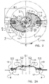
- the cutting disc assemblies have two blades 8 situated at opposite positions.
- Each blade 8 is provided with a cutting edge 9, which is directed in the direction of rotation C.
- each blade 8 is attached to a dedicated blade holder 11a, 11b, each of which is bent and panel-shaped (with the concave side on top) and, viewed in top view, have gaps 30 between them.
- the blade holders 11a,b have a leading edge region 13, which is formed in order to pass plants mowed by the preceding blade upwards, and a trailing edge region 14.
- the blade holders 11a,b are rotatably attached to a flange 21 of a hub 20 by means of bolts 15, illustrated in more detail in Fig.
- the blades 8 themselves are attached to the dedicated blade holder 11a, 11b so as to be rotatable about rotation axis S3 of the pivot pin 10, with the pivot angle being limited by a stop at the bottom side of the respective blade holder, if desired.
- the rotation axes S1 and S3 are vertical and parallel to one another.
- the blade holders 11a,b are furthermore fixed to the flange 21 by means of breaking pins 16, as a result of which, during normal operation, without impact, they are held against rotation about rotation axis S2. However, following breaking of the breaking pin 16, they are potentially rotatable about said axis.
- the hub 20 is attached to a gearwheel 25 which is driven by a drive shaft 27 via a right-angled transmission with gearwheel 26.
- the drive shaft 27 is indirectly driven by the power take-off 3 and extends in the longitudinal direction of the mowing beam 6 through housing 28 and drives several cutting disc assemblies which are arranged next to one another.
- the central rotation axis S1 of the cutting disc assembly 7 is indicated.
- the outer path X1 of the ends of the blades 8, having a radius R1 is indicated and the outer path Y1 of the edge of the blade holders 11a,b is, having a radius R3, indicated.
- the blade holder By drawing a radial T running through hinge 15, the blade holder can be seen divided into a first portion I and a second portion II, which also carries the blade 8.
- the first portion I has a mass which is greater than that of the second portion II.
- a blade 8 hits a hard foreign object, such as a stone, the blade can turn inwards about rotation axis S3. If the impact force experienced exceeds a specific value, the respective blade holder 11a, 11b can exert a force on the connection with the hub 20, as a result of which the breaking force of the breaking pin 16 is exceeded. This may also occur when the blade holder 11a, 11b itself hits the foreign object. In this case, it should be considered, that the speed in the direction A may be 15 km/h and the rotary speed of the cutting disc assembly 7 may be 3000/min. As a result of the breaking of the breaking pin 16, the respective blade holder remains connected to the hub 20 only at the location of bolt 15.
- portion I As a result of the larger mass of portion I, the latter will bend outwards and the second portion II will bend inwards about the hinge 15 and rotation axis S2.
- the outer path X2 of the respective blade end will now take up a smaller radius R2.
- the outer path Y2 of the edge of the blade holders 11a,b will also take up a smaller radius R4. The same will happen if the other blade and/or the other blade holder also hits the same hard object.
- the two blade ends and blade holders remain in the retracted position, in which they are outside the path of the blade ends and blade holders of the adjacent cutting disc assemblies.
- a stop 24 may be provided on the hub or the other blade holder by means of which the blade holder is held in the position from Fig. 3 .
- a clamping means may be provided on the hub 20 or on the other blade holder 11b;11a, by means of which the inward rotation of the blade holder 11a;11b is limited.
- breaking pins 16 into a single shearing connection which is active directly between both blade holders 11a,b, for example in the form of a pull strip (not shown).
- the blade holders may overlap at the location of a single breaking pin which extends through both blade holders and the rest of the rotor, such as hub 20.
- the rotation axis S2 may be allowed to be at an angle, by designing the hole in the flange 21 for the bolt 15 accordingly ( Fig. 4A ).
- the angle ⁇ of the ascending surfaces 29 and of rotation axis S2 may be in the order of magnitude of 10-20 degrees, so that the vertical displacement can take place quickly.
- the direction of the inclination can be related to the cutting edge of the blade 8, in particular the end thereof, so that this moves directly upwards after the breaking pin 16 has broken. In Fig.
- the line v has been rendered as a spot, which line, on the one hand, contains the intersection of a vertical and the rotation axis S2 and contains, on the other hand, the end of the cutting edge of the blade 8 (see also Fig. 4 ).
- the rotation axis will be situated in the upward direction on the trailing side (based on the direction of rotation D after impact) of the vertical.
- the rotation axis S2 is in this case inclined at an angle ⁇ of, for example, the abovementioned 10-20 degrees.
Landscapes
- Life Sciences & Earth Sciences (AREA)
- Environmental Sciences (AREA)
- Harvester Elements (AREA)
Priority Applications (1)
| Application Number | Priority Date | Filing Date | Title |
|---|---|---|---|
| PL12165759T PL2520149T3 (pl) | 2008-02-18 | 2009-02-11 | Urządzenie do koszenia |
Applications Claiming Priority (2)
| Application Number | Priority Date | Filing Date | Title |
|---|---|---|---|
| NL1035035A NL1035035C2 (nl) | 2008-02-18 | 2008-02-18 | Maai-inrichting. |
| EP09075069.6A EP2090150B1 (en) | 2008-02-18 | 2009-02-11 | Mowing device |
Related Parent Applications (2)
| Application Number | Title | Priority Date | Filing Date |
|---|---|---|---|
| EP09075069.6 Division | 2009-02-11 | ||
| EP09075069.6A Division-Into EP2090150B1 (en) | 2008-02-18 | 2009-02-11 | Mowing device |
Publications (2)
| Publication Number | Publication Date |
|---|---|
| EP2520149A1 EP2520149A1 (en) | 2012-11-07 |
| EP2520149B1 true EP2520149B1 (en) | 2013-12-04 |
Family
ID=39760838
Family Applications (3)
| Application Number | Title | Priority Date | Filing Date |
|---|---|---|---|
| EP12165759.7A Not-in-force EP2520149B1 (en) | 2008-02-18 | 2009-02-11 | Mowing device |
| EP09075069.6A Not-in-force EP2090150B1 (en) | 2008-02-18 | 2009-02-11 | Mowing device |
| EP12165761.3A Not-in-force EP2520150B1 (en) | 2008-02-18 | 2009-02-11 | Mowing device |
Family Applications After (2)
| Application Number | Title | Priority Date | Filing Date |
|---|---|---|---|
| EP09075069.6A Not-in-force EP2090150B1 (en) | 2008-02-18 | 2009-02-11 | Mowing device |
| EP12165761.3A Not-in-force EP2520150B1 (en) | 2008-02-18 | 2009-02-11 | Mowing device |
Country Status (5)
| Country | Link |
|---|---|
| US (3) | US8205423B2 (pl) |
| EP (3) | EP2520149B1 (pl) |
| DK (2) | DK2520149T3 (pl) |
| NL (1) | NL1035035C2 (pl) |
| PL (2) | PL2520150T3 (pl) |
Cited By (1)
| Publication number | Priority date | Publication date | Assignee | Title |
|---|---|---|---|---|
| PL245898B1 (pl) * | 2021-03-17 | 2024-10-28 | Osrodek Techniki Lesnej | Urządzenie do wykaszania, zwłaszcza obszarów leśnych |
Families Citing this family (9)
| Publication number | Priority date | Publication date | Assignee | Title |
|---|---|---|---|---|
| NL1035035C2 (nl) * | 2008-02-18 | 2009-08-19 | Lely Patent Nv | Maai-inrichting. |
| IT1401699B1 (it) * | 2010-09-13 | 2013-08-02 | Feraboli S P A | Gruppo falciante a dischi, particolarmente per macchine agricole del tipo falciatrici, falciacondizionatrici o simili, ad elevata sicurezza di impiego. |
| US8695316B2 (en) * | 2011-02-21 | 2014-04-15 | Agco Corporation | Fixed rotary knife with multiple cutting surfaces |
| EP2760270B1 (en) | 2011-09-29 | 2016-11-16 | Husqvarna AB | Quick-change blade system |
| US10188031B2 (en) * | 2016-01-27 | 2019-01-29 | Great Plains Manufacturing, Inc. | Cutter blade and assembly for a rotary cutter |
| US11470773B2 (en) | 2017-08-02 | 2022-10-18 | Briggs & Stratton, Llc | Stand-on mower with an oscillating front axle |
| US10820499B2 (en) * | 2018-06-08 | 2020-11-03 | Cnh Industrial America Llc | Hybrid disc cutting system having a knife mount for an agricultural vehicle |
| DE102020119368B4 (de) * | 2020-07-22 | 2024-10-24 | Maschinenfabrik Bernard Krone GmbH & Co. KG | Schneidvorrichtung |
| US12376519B2 (en) | 2022-06-14 | 2025-08-05 | Deere & Company | Quick change blade for a rotating blade assembly of a mower implement |
Family Cites Families (62)
| Publication number | Priority date | Publication date | Assignee | Title |
|---|---|---|---|---|
| US1220353A (en) * | 1916-02-21 | 1917-03-27 | Lindbladh Corp | Delivery device. |
| US2547540A (en) * | 1946-03-14 | 1951-04-03 | Wiley T Roberts | Power mower |
| US2634571A (en) * | 1951-05-07 | 1953-04-14 | Forby W Lawrence | Rotary hinged disk type mower |
| US2856747A (en) * | 1955-09-30 | 1958-10-21 | Ernest W Kolls | Cutting blade for rotary type mowing machines |
| US2963844A (en) * | 1959-04-20 | 1960-12-13 | John F Engler | Mower blade |
| US3184907A (en) * | 1964-03-16 | 1965-05-25 | Werner B Harloff | Power mower |
| US3320732A (en) * | 1965-02-17 | 1967-05-23 | Ralph D Kirk | Cutting blade assembly for rotary lawn mowers and the like |
| US3397525A (en) * | 1965-07-01 | 1968-08-20 | Int Harvester Co | Breakaway knife holder |
| US3507104A (en) * | 1967-05-25 | 1970-04-21 | Sperry Rand Corp | Knife mounting |
| US3500622A (en) * | 1967-08-17 | 1970-03-17 | Marvin Bowen | Mower cutting blade |
| GB1220353A (en) * | 1967-10-27 | 1971-01-27 | Bamlett Ltd A C | Improvements in or relating to flail mowers and flail shaft arrangements therefor |
| DE6811860U (de) * | 1968-12-18 | 1969-05-14 | Welger Geb | Messerbefestigung an scheiben- oder trommelmaehwerken |
| GB1321595A (en) * | 1969-07-16 | 1973-06-27 | Kidd A W | Machines for cutting crops |
| US3621642A (en) * | 1970-10-09 | 1971-11-23 | Harry A Leake Jr | Rotary cutter head assembly for lawn mowers |
| US3715874A (en) * | 1971-10-01 | 1973-02-13 | C Goserud | Lawn mower cutters |
| US3690051A (en) * | 1971-12-28 | 1972-09-12 | Black & Decker Mfg Co | Safety lawnmower blade |
| DE2316308A1 (de) * | 1973-03-31 | 1974-10-17 | Mang Albert | Maehmaschine, insbesondere rasen-maehmaschine |
| CA1005648A (en) * | 1974-05-10 | 1977-02-22 | International Harvester Company | Cutter blade mounting for a rotary mower |
| US3918241A (en) * | 1974-10-16 | 1975-11-11 | Herbert C Stillions | Cutting unit for rotary lawn mowers |
| US4058959A (en) * | 1975-10-06 | 1977-11-22 | Moss Robert J | Grass cutting blades |
| NL7513925A (nl) * | 1975-11-28 | 1977-06-01 | Multinorm Bv | Maaiinrichting. |
| US4062171A (en) * | 1976-08-30 | 1977-12-13 | Massey-Ferguson Inc. | Cutter blade assembly |
| US4114354A (en) * | 1976-11-05 | 1978-09-19 | Outboard Marine Corporation | Lawn mower blade mounting |
| US4345420A (en) * | 1977-09-12 | 1982-08-24 | Multinorm, B.V. | Mowing implement |
| US4158944A (en) * | 1977-09-20 | 1979-06-26 | Hall & Myers | Rotary blade coupling for lawn mower |
| US4258536A (en) * | 1979-02-07 | 1981-03-31 | Outboard Marine Corporation | Power rotary cutting blade with retractable cutting knives |
| DE2920244C2 (de) * | 1979-05-18 | 1986-10-23 | Klöckner-Humboldt-Deutz AG Zweigniederlassung Fahr, 7702 Gottmadingen | Kreiselmäher |
| NL8101567A (nl) * | 1981-03-30 | 1981-08-03 | Multinorm Bv | Maaiinrichting. |
| NL8103411A (nl) * | 1981-07-17 | 1983-02-16 | Multinorm Bv | Maaier. |
| NL8104178A (nl) * | 1981-09-10 | 1983-04-05 | Lely Nv C Van Der | Flexibele maaikap. |
| NL8105634A (nl) * | 1981-12-15 | 1983-07-01 | Zweegers P | Inrichting voor het maaien van gewas. |
| NL8400028A (nl) * | 1984-01-04 | 1985-08-01 | Lely Nv C Van Der | Maaimachine. |
| US4651510A (en) * | 1985-04-08 | 1987-03-24 | Malutich William J | Blade for rotary lawn mower |
| US4804047A (en) * | 1985-11-20 | 1989-02-14 | Kobashi Kogyo Co., Ltd. | Rotary mower and tilling device |
| FR2638056B1 (fr) * | 1988-10-26 | 1991-06-07 | Kuhn Sa | Faucheuse avec montage perfectionne des organes de coupe |
| DK162802C (da) * | 1989-04-20 | 1992-05-04 | Spragelse Maskinfabrik As | Rotorklipper |
| US5271212A (en) * | 1992-12-23 | 1993-12-21 | Anderson Ray S | Lawnmower blade with yieldable opposite outer cutting sections |
| US5581985A (en) * | 1995-06-15 | 1996-12-10 | Secosky; Paul M. | Safety clutches for self power operated lawn mowers |
| CA2178535C (en) * | 1995-08-30 | 1999-08-31 | Deere & Company | Shredding attachment for rotary cutter |
| US5649413A (en) * | 1995-11-14 | 1997-07-22 | Oostendorp; William E. | Grass trimming and lawn edging device |
| US5715662A (en) * | 1995-11-17 | 1998-02-10 | Deere & Company | Drive shear device for rotary cutter unit |
| US5791131A (en) * | 1996-04-22 | 1998-08-11 | Snapper, Inc. | Convertible mower blade |
| AUPO739097A0 (en) * | 1997-06-16 | 1997-07-10 | Thorne, Peter | Improved brush cutting tool |
| DE19748475C2 (de) * | 1997-11-03 | 1999-08-19 | Horst Staiger & Soehne Gmbh | Mähwerk für Rasenmäher |
| WO1999041966A1 (en) * | 1998-02-20 | 1999-08-26 | The Black & Decker Corporation | Combination string and blade trimmer with auxiliary blower function |
| FR2776953B1 (fr) * | 1998-04-07 | 2001-10-12 | Edouard Boisson | Organe de coupe semi-rigide a rendement ameliore |
| US20020095921A1 (en) * | 2001-01-25 | 2002-07-25 | The Master's Dredging Company, Inc. | Airboat with aquatic vegetation shredding assembly |
| US6604347B2 (en) * | 2001-04-27 | 2003-08-12 | New Holland North America, Inc. | Energy absorber for hubs of agricultural disc drive |
| US6502377B2 (en) * | 2001-04-27 | 2003-01-07 | New Holland North America, Inc. | Brake for a disc cutterbar |
| US6487835B2 (en) * | 2001-04-27 | 2002-12-03 | New Holland North America, Inc. | Overload protection for a disc cutterbar |
| US6688193B2 (en) * | 2002-01-24 | 2004-02-10 | Deere & Company | Rotary blade cutterbar including plastic idler gear support hub with metal insert |
| US6675563B1 (en) * | 2002-08-19 | 2004-01-13 | New Holland North America, Inc | Disc cutterbar shear protection |
| US6834486B2 (en) * | 2003-03-12 | 2004-12-28 | Vermeer Manufacturing Company | Pivotal knife mounting arrangement |
| US7490459B2 (en) * | 2003-03-12 | 2009-02-17 | Vermeer Manufacturing Company | Mowing device, a knife adapter for such a mowing device and a retainer for such a mowing device |
| US20050193706A1 (en) * | 2003-03-12 | 2005-09-08 | Kent Thompson | Mowing device, a knife adapter for such a mowing device and a retainer for such a mowing device |
| US6829878B1 (en) * | 2004-03-29 | 2004-12-14 | Cnh America Llc | Quick change disc knife mounting mechanism |
| US20060021316A1 (en) * | 2004-07-28 | 2006-02-02 | Harkcom Melanie W | Disc cutterbar shear device |
| US7506494B2 (en) * | 2005-01-18 | 2009-03-24 | Commercial Turf Products, Ltd. | Pivot-blade cutting and retaining means for rotary mowers |
| WO2006135952A1 (en) * | 2005-04-29 | 2006-12-28 | Raymond Eric Abernethy | A cutting blade assembly for a mower |
| US7543432B1 (en) * | 2008-01-29 | 2009-06-09 | Honda Motor Co., Ltd. | Retractable blade cutting apparatuses and methods for mowing machines |
| NL1035035C2 (nl) * | 2008-02-18 | 2009-08-19 | Lely Patent Nv | Maai-inrichting. |
| WO2010151871A2 (en) * | 2009-06-26 | 2010-12-29 | Leonardi Manufacturing Co. Inc. | Electrically-powered combination lawn mower, trimmer and edger |
-
2008
- 2008-02-18 NL NL1035035A patent/NL1035035C2/nl not_active IP Right Cessation
-
2009
- 2009-02-11 EP EP12165759.7A patent/EP2520149B1/en not_active Not-in-force
- 2009-02-11 EP EP09075069.6A patent/EP2090150B1/en not_active Not-in-force
- 2009-02-11 DK DK12165759.7T patent/DK2520149T3/da active
- 2009-02-11 DK DK12165761.3T patent/DK2520150T3/da active
- 2009-02-11 EP EP12165761.3A patent/EP2520150B1/en not_active Not-in-force
- 2009-02-11 PL PL12165761T patent/PL2520150T3/pl unknown
- 2009-02-11 PL PL12165759T patent/PL2520149T3/pl unknown
- 2009-02-13 US US12/370,658 patent/US8205423B2/en not_active Expired - Fee Related
-
2012
- 2012-05-25 US US13/480,537 patent/US8707665B2/en active Active
-
2014
- 2014-03-05 US US14/197,237 patent/US20140182258A1/en not_active Abandoned
Cited By (1)
| Publication number | Priority date | Publication date | Assignee | Title |
|---|---|---|---|---|
| PL245898B1 (pl) * | 2021-03-17 | 2024-10-28 | Osrodek Techniki Lesnej | Urządzenie do wykaszania, zwłaszcza obszarów leśnych |
Also Published As
| Publication number | Publication date |
|---|---|
| DK2520149T3 (da) | 2014-02-03 |
| US20090205305A1 (en) | 2009-08-20 |
| EP2090150A2 (en) | 2009-08-19 |
| US8205423B2 (en) | 2012-06-26 |
| US20140182258A1 (en) | 2014-07-03 |
| NL1035035C2 (nl) | 2009-08-19 |
| US20120240545A1 (en) | 2012-09-27 |
| PL2520150T3 (pl) | 2014-05-30 |
| EP2090150A3 (en) | 2009-11-18 |
| PL2520149T3 (pl) | 2014-05-30 |
| EP2520150A1 (en) | 2012-11-07 |
| DK2520150T3 (da) | 2014-02-10 |
| EP2520149A1 (en) | 2012-11-07 |
| EP2520150B1 (en) | 2013-12-25 |
| EP2090150B1 (en) | 2018-08-29 |
| US8707665B2 (en) | 2014-04-29 |
Similar Documents
| Publication | Publication Date | Title |
|---|---|---|
| EP2520149B1 (en) | Mowing device | |
| US8510959B2 (en) | Quick-change disc mower knives | |
| US5809757A (en) | Protective structure for a modular disc cutterbar | |
| US12083524B2 (en) | Centrifugal pulverizing mill | |
| US3905182A (en) | Rotary mower | |
| JP2009106257A (ja) | 草刈機用刃物盤 | |
| JPH09509823A (ja) | 切断工具 | |
| US20100043378A1 (en) | cutting blade assembly for a mower | |
| US3540198A (en) | Swing knife assembly for a rotary mower | |
| JP2010178751A (ja) | 刈払機用回転刃およびこれを用いた刈払機 | |
| CA2990512C (en) | Rotary cutter unit | |
| US5144748A (en) | Cleaning device | |
| JP6773479B2 (ja) | 草刈機 | |
| FI131707B1 (sv) | Drivenhet för tallriksslåttermaskin | |
| EP0592403B1 (en) | Blade protector for clearing machine | |
| JP3474851B2 (ja) | 回転刃およびそのブレード | |
| KR200367628Y1 (ko) | 예초기용 예초날 | |
| JP2013017464A (ja) | 動力草刈り機の刃物 | |
| US3485021A (en) | Protective device for rotary cutters | |
| KR20230069353A (ko) | 지면에 근접하여 절단이 가능한 작물 예취기 | |
| KR20050099461A (ko) | 예취기용 칼날 | |
| JP2010057444A (ja) | 草刈り機械の草刈り刃 | |
| CA2271966A1 (en) | Disc and knife cutter assembly for mowing | |
| CN120898630A (zh) | 一种具备升降和摆动功能的割草机器人 | |
| CN117136705A (zh) | 切割装置和具有该切割装置的切割设备 |
Legal Events
| Date | Code | Title | Description |
|---|---|---|---|
| PUAI | Public reference made under article 153(3) epc to a published international application that has entered the european phase |
Free format text: ORIGINAL CODE: 0009012 |
|
| AC | Divisional application: reference to earlier application |
Ref document number: 2090150 Country of ref document: EP Kind code of ref document: P |
|
| AK | Designated contracting states |
Kind code of ref document: A1 Designated state(s): AT BE BG CH CY CZ DE DK EE ES FI FR GB GR HR HU IE IS IT LI LT LU LV MC MK MT NL NO PL PT RO SE SI SK TR |
|
| 17P | Request for examination filed |
Effective date: 20130507 |
|
| GRAP | Despatch of communication of intention to grant a patent |
Free format text: ORIGINAL CODE: EPIDOSNIGR1 |
|
| RIC1 | Information provided on ipc code assigned before grant |
Ipc: A01D 34/73 20060101AFI20130701BHEP Ipc: A01D 34/82 20060101ALI20130701BHEP |
|
| INTG | Intention to grant announced |
Effective date: 20130723 |
|
| GRAS | Grant fee paid |
Free format text: ORIGINAL CODE: EPIDOSNIGR3 |
|
| GRAA | (expected) grant |
Free format text: ORIGINAL CODE: 0009210 |
|
| AC | Divisional application: reference to earlier application |
Ref document number: 2090150 Country of ref document: EP Kind code of ref document: P |
|
| AK | Designated contracting states |
Kind code of ref document: B1 Designated state(s): AT BE BG CH CY CZ DE DK EE ES FI FR GB GR HR HU IE IS IT LI LT LU LV MC MK MT NL NO PL PT RO SE SI SK TR |
|
| REG | Reference to a national code |
Ref country code: GB Ref legal event code: FG4D |
|
| REG | Reference to a national code |
Ref country code: CH Ref legal event code: EP |
|
| REG | Reference to a national code |
Ref country code: AT Ref legal event code: REF Ref document number: 643126 Country of ref document: AT Kind code of ref document: T Effective date: 20140115 Ref country code: IE Ref legal event code: FG4D |
|
| REG | Reference to a national code |
Ref country code: DE Ref legal event code: R096 Ref document number: 602009020593 Country of ref document: DE Effective date: 20140130 |
|
| REG | Reference to a national code |
Ref country code: DK Ref legal event code: T3 Effective date: 20140131 |
|
| REG | Reference to a national code |
Ref country code: NL Ref legal event code: T3 |
|
| PG25 | Lapsed in a contracting state [announced via postgrant information from national office to epo] |
Ref country code: FI Free format text: LAPSE BECAUSE OF FAILURE TO SUBMIT A TRANSLATION OF THE DESCRIPTION OR TO PAY THE FEE WITHIN THE PRESCRIBED TIME-LIMIT Effective date: 20131204 Ref country code: NO Free format text: LAPSE BECAUSE OF FAILURE TO SUBMIT A TRANSLATION OF THE DESCRIPTION OR TO PAY THE FEE WITHIN THE PRESCRIBED TIME-LIMIT Effective date: 20140304 Ref country code: SE Free format text: LAPSE BECAUSE OF FAILURE TO SUBMIT A TRANSLATION OF THE DESCRIPTION OR TO PAY THE FEE WITHIN THE PRESCRIBED TIME-LIMIT Effective date: 20131204 Ref country code: HR Free format text: LAPSE BECAUSE OF FAILURE TO SUBMIT A TRANSLATION OF THE DESCRIPTION OR TO PAY THE FEE WITHIN THE PRESCRIBED TIME-LIMIT Effective date: 20131204 Ref country code: LT Free format text: LAPSE BECAUSE OF FAILURE TO SUBMIT A TRANSLATION OF THE DESCRIPTION OR TO PAY THE FEE WITHIN THE PRESCRIBED TIME-LIMIT Effective date: 20131204 |
|
| REG | Reference to a national code |
Ref country code: LT Ref legal event code: MG4D |
|
| PG25 | Lapsed in a contracting state [announced via postgrant information from national office to epo] |
Ref country code: CY Free format text: LAPSE BECAUSE OF FAILURE TO SUBMIT A TRANSLATION OF THE DESCRIPTION OR TO PAY THE FEE WITHIN THE PRESCRIBED TIME-LIMIT Effective date: 20131204 Ref country code: LV Free format text: LAPSE BECAUSE OF FAILURE TO SUBMIT A TRANSLATION OF THE DESCRIPTION OR TO PAY THE FEE WITHIN THE PRESCRIBED TIME-LIMIT Effective date: 20131204 |
|
| REG | Reference to a national code |
Ref country code: PL Ref legal event code: T3 |
|
| REG | Reference to a national code |
Ref country code: HU Ref legal event code: AG4A Ref document number: E019588 Country of ref document: HU |
|
| PG25 | Lapsed in a contracting state [announced via postgrant information from national office to epo] |
Ref country code: IS Free format text: LAPSE BECAUSE OF FAILURE TO SUBMIT A TRANSLATION OF THE DESCRIPTION OR TO PAY THE FEE WITHIN THE PRESCRIBED TIME-LIMIT Effective date: 20140404 Ref country code: EE Free format text: LAPSE BECAUSE OF FAILURE TO SUBMIT A TRANSLATION OF THE DESCRIPTION OR TO PAY THE FEE WITHIN THE PRESCRIBED TIME-LIMIT Effective date: 20131204 Ref country code: BE Free format text: LAPSE BECAUSE OF FAILURE TO SUBMIT A TRANSLATION OF THE DESCRIPTION OR TO PAY THE FEE WITHIN THE PRESCRIBED TIME-LIMIT Effective date: 20131204 |
|
| PG25 | Lapsed in a contracting state [announced via postgrant information from national office to epo] |
Ref country code: PT Free format text: LAPSE BECAUSE OF FAILURE TO SUBMIT A TRANSLATION OF THE DESCRIPTION OR TO PAY THE FEE WITHIN THE PRESCRIBED TIME-LIMIT Effective date: 20140404 Ref country code: CZ Free format text: LAPSE BECAUSE OF FAILURE TO SUBMIT A TRANSLATION OF THE DESCRIPTION OR TO PAY THE FEE WITHIN THE PRESCRIBED TIME-LIMIT Effective date: 20131204 Ref country code: ES Free format text: LAPSE BECAUSE OF FAILURE TO SUBMIT A TRANSLATION OF THE DESCRIPTION OR TO PAY THE FEE WITHIN THE PRESCRIBED TIME-LIMIT Effective date: 20131204 Ref country code: RO Free format text: LAPSE BECAUSE OF FAILURE TO SUBMIT A TRANSLATION OF THE DESCRIPTION OR TO PAY THE FEE WITHIN THE PRESCRIBED TIME-LIMIT Effective date: 20131204 Ref country code: SK Free format text: LAPSE BECAUSE OF FAILURE TO SUBMIT A TRANSLATION OF THE DESCRIPTION OR TO PAY THE FEE WITHIN THE PRESCRIBED TIME-LIMIT Effective date: 20131204 |
|
| REG | Reference to a national code |
Ref country code: DE Ref legal event code: R097 Ref document number: 602009020593 Country of ref document: DE |
|
| PG25 | Lapsed in a contracting state [announced via postgrant information from national office to epo] |
Ref country code: LU Free format text: LAPSE BECAUSE OF FAILURE TO SUBMIT A TRANSLATION OF THE DESCRIPTION OR TO PAY THE FEE WITHIN THE PRESCRIBED TIME-LIMIT Effective date: 20140211 Ref country code: MC Free format text: LAPSE BECAUSE OF FAILURE TO SUBMIT A TRANSLATION OF THE DESCRIPTION OR TO PAY THE FEE WITHIN THE PRESCRIBED TIME-LIMIT Effective date: 20131204 |
|
| REG | Reference to a national code |
Ref country code: CH Ref legal event code: PL |
|
| PLBE | No opposition filed within time limit |
Free format text: ORIGINAL CODE: 0009261 |
|
| STAA | Information on the status of an ep patent application or granted ep patent |
Free format text: STATUS: NO OPPOSITION FILED WITHIN TIME LIMIT |
|
| PG25 | Lapsed in a contracting state [announced via postgrant information from national office to epo] |
Ref country code: CH Free format text: LAPSE BECAUSE OF NON-PAYMENT OF DUE FEES Effective date: 20140228 Ref country code: LI Free format text: LAPSE BECAUSE OF NON-PAYMENT OF DUE FEES Effective date: 20140228 |
|
| 26N | No opposition filed |
Effective date: 20140905 |
|
| REG | Reference to a national code |
Ref country code: DE Ref legal event code: R097 Ref document number: 602009020593 Country of ref document: DE Effective date: 20140905 |
|
| PG25 | Lapsed in a contracting state [announced via postgrant information from national office to epo] |
Ref country code: SI Free format text: LAPSE BECAUSE OF FAILURE TO SUBMIT A TRANSLATION OF THE DESCRIPTION OR TO PAY THE FEE WITHIN THE PRESCRIBED TIME-LIMIT Effective date: 20131204 |
|
| PGFP | Annual fee paid to national office [announced via postgrant information from national office to epo] |
Ref country code: IE Payment date: 20150227 Year of fee payment: 7 Ref country code: IT Payment date: 20150220 Year of fee payment: 7 Ref country code: DK Payment date: 20150225 Year of fee payment: 7 |
|
| REG | Reference to a national code |
Ref country code: FR Ref legal event code: PLFP Year of fee payment: 8 |
|
| PG25 | Lapsed in a contracting state [announced via postgrant information from national office to epo] |
Ref country code: MT Free format text: LAPSE BECAUSE OF FAILURE TO SUBMIT A TRANSLATION OF THE DESCRIPTION OR TO PAY THE FEE WITHIN THE PRESCRIBED TIME-LIMIT Effective date: 20131204 |
|
| PGFP | Annual fee paid to national office [announced via postgrant information from national office to epo] |
Ref country code: TR Payment date: 20160125 Year of fee payment: 8 |
|
| PG25 | Lapsed in a contracting state [announced via postgrant information from national office to epo] |
Ref country code: BG Free format text: LAPSE BECAUSE OF FAILURE TO SUBMIT A TRANSLATION OF THE DESCRIPTION OR TO PAY THE FEE WITHIN THE PRESCRIBED TIME-LIMIT Effective date: 20131204 |
|
| PGFP | Annual fee paid to national office [announced via postgrant information from national office to epo] |
Ref country code: AT Payment date: 20160120 Year of fee payment: 8 Ref country code: PL Payment date: 20160125 Year of fee payment: 8 Ref country code: HU Payment date: 20160125 Year of fee payment: 8 |
|
| PG25 | Lapsed in a contracting state [announced via postgrant information from national office to epo] |
Ref country code: GR Free format text: LAPSE BECAUSE OF FAILURE TO SUBMIT A TRANSLATION OF THE DESCRIPTION OR TO PAY THE FEE WITHIN THE PRESCRIBED TIME-LIMIT Effective date: 20140305 |
|
| REG | Reference to a national code |
Ref country code: DK Ref legal event code: EBP Effective date: 20160229 |
|
| REG | Reference to a national code |
Ref country code: IE Ref legal event code: MM4A |
|
| PG25 | Lapsed in a contracting state [announced via postgrant information from national office to epo] |
Ref country code: IT Free format text: LAPSE BECAUSE OF NON-PAYMENT OF DUE FEES Effective date: 20160211 |
|
| PG25 | Lapsed in a contracting state [announced via postgrant information from national office to epo] |
Ref country code: DK Free format text: LAPSE BECAUSE OF NON-PAYMENT OF DUE FEES Effective date: 20160229 Ref country code: IE Free format text: LAPSE BECAUSE OF NON-PAYMENT OF DUE FEES Effective date: 20160211 |
|
| REG | Reference to a national code |
Ref country code: FR Ref legal event code: PLFP Year of fee payment: 9 |
|
| REG | Reference to a national code |
Ref country code: AT Ref legal event code: MM01 Ref document number: 643126 Country of ref document: AT Kind code of ref document: T Effective date: 20170211 |
|
| PG25 | Lapsed in a contracting state [announced via postgrant information from national office to epo] |
Ref country code: AT Free format text: LAPSE BECAUSE OF NON-PAYMENT OF DUE FEES Effective date: 20170211 |
|
| PG25 | Lapsed in a contracting state [announced via postgrant information from national office to epo] |
Ref country code: HU Free format text: LAPSE BECAUSE OF NON-PAYMENT OF DUE FEES Effective date: 20170212 |
|
| REG | Reference to a national code |
Ref country code: FR Ref legal event code: PLFP Year of fee payment: 10 |
|
| PGFP | Annual fee paid to national office [announced via postgrant information from national office to epo] |
Ref country code: GB Payment date: 20180216 Year of fee payment: 10 |
|
| PG25 | Lapsed in a contracting state [announced via postgrant information from national office to epo] |
Ref country code: MK Free format text: LAPSE BECAUSE OF FAILURE TO SUBMIT A TRANSLATION OF THE DESCRIPTION OR TO PAY THE FEE WITHIN THE PRESCRIBED TIME-LIMIT Effective date: 20131204 |
|
| PG25 | Lapsed in a contracting state [announced via postgrant information from national office to epo] |
Ref country code: PL Free format text: LAPSE BECAUSE OF NON-PAYMENT OF DUE FEES Effective date: 20170211 |
|
| GBPC | Gb: european patent ceased through non-payment of renewal fee |
Effective date: 20190211 |
|
| PG25 | Lapsed in a contracting state [announced via postgrant information from national office to epo] |
Ref country code: GB Free format text: LAPSE BECAUSE OF NON-PAYMENT OF DUE FEES Effective date: 20190211 |
|
| PGFP | Annual fee paid to national office [announced via postgrant information from national office to epo] |
Ref country code: NL Payment date: 20230216 Year of fee payment: 15 |
|
| PGFP | Annual fee paid to national office [announced via postgrant information from national office to epo] |
Ref country code: FR Payment date: 20230221 Year of fee payment: 15 |
|
| PGFP | Annual fee paid to national office [announced via postgrant information from national office to epo] |
Ref country code: DE Payment date: 20230216 Year of fee payment: 15 |
|
| REG | Reference to a national code |
Ref country code: DE Ref legal event code: R119 Ref document number: 602009020593 Country of ref document: DE |
|
| PG25 | Lapsed in a contracting state [announced via postgrant information from national office to epo] |
Ref country code: TR Free format text: LAPSE BECAUSE OF NON-PAYMENT OF DUE FEES Effective date: 20170211 |
|
| REG | Reference to a national code |
Ref country code: NL Ref legal event code: MM Effective date: 20240301 |
|
| PG25 | Lapsed in a contracting state [announced via postgrant information from national office to epo] |
Ref country code: NL Free format text: LAPSE BECAUSE OF NON-PAYMENT OF DUE FEES Effective date: 20240301 |
|
| PG25 | Lapsed in a contracting state [announced via postgrant information from national office to epo] |
Ref country code: NL Free format text: LAPSE BECAUSE OF NON-PAYMENT OF DUE FEES Effective date: 20240301 |
|
| PG25 | Lapsed in a contracting state [announced via postgrant information from national office to epo] |
Ref country code: DE Free format text: LAPSE BECAUSE OF NON-PAYMENT OF DUE FEES Effective date: 20240903 |
|
| PG25 | Lapsed in a contracting state [announced via postgrant information from national office to epo] |
Ref country code: FR Free format text: LAPSE BECAUSE OF NON-PAYMENT OF DUE FEES Effective date: 20240229 |
|
| PG25 | Lapsed in a contracting state [announced via postgrant information from national office to epo] |
Ref country code: FR Free format text: LAPSE BECAUSE OF NON-PAYMENT OF DUE FEES Effective date: 20240229 Ref country code: DE Free format text: LAPSE BECAUSE OF NON-PAYMENT OF DUE FEES Effective date: 20240903 |