EP2517784B1 - Pre-mixing device between two fluids for a reactor with a catalytic bed - Google Patents
Pre-mixing device between two fluids for a reactor with a catalytic bed Download PDFInfo
- Publication number
- EP2517784B1 EP2517784B1 EP12175556.5A EP12175556A EP2517784B1 EP 2517784 B1 EP2517784 B1 EP 2517784B1 EP 12175556 A EP12175556 A EP 12175556A EP 2517784 B1 EP2517784 B1 EP 2517784B1
- Authority
- EP
- European Patent Office
- Prior art keywords
- tubes
- perforated plate
- mixing
- openings
- finned
- Prior art date
- Legal status (The legal status is an assumption and is not a legal conclusion. Google has not performed a legal analysis and makes no representation as to the accuracy of the status listed.)
- Not-in-force
Links
Images


Classifications
-
- B—PERFORMING OPERATIONS; TRANSPORTING
- B01—PHYSICAL OR CHEMICAL PROCESSES OR APPARATUS IN GENERAL
- B01F—MIXING, e.g. DISSOLVING, EMULSIFYING OR DISPERSING
- B01F25/00—Flow mixers; Mixers for falling materials, e.g. solid particles
- B01F25/30—Injector mixers
- B01F25/31—Injector mixers in conduits or tubes through which the main component flows
- B01F25/313—Injector mixers in conduits or tubes through which the main component flows wherein additional components are introduced in the centre of the conduit
- B01F25/3132—Injector mixers in conduits or tubes through which the main component flows wherein additional components are introduced in the centre of the conduit by using two or more injector devices
-
- B—PERFORMING OPERATIONS; TRANSPORTING
- B01—PHYSICAL OR CHEMICAL PROCESSES OR APPARATUS IN GENERAL
- B01F—MIXING, e.g. DISSOLVING, EMULSIFYING OR DISPERSING
- B01F25/00—Flow mixers; Mixers for falling materials, e.g. solid particles
- B01F25/30—Injector mixers
-
- B—PERFORMING OPERATIONS; TRANSPORTING
- B01—PHYSICAL OR CHEMICAL PROCESSES OR APPARATUS IN GENERAL
- B01J—CHEMICAL OR PHYSICAL PROCESSES, e.g. CATALYSIS OR COLLOID CHEMISTRY; THEIR RELEVANT APPARATUS
- B01J8/00—Chemical or physical processes in general, conducted in the presence of fluids and solid particles; Apparatus for such processes
- B01J8/008—Details of the reactor or of the particulate material; Processes to increase or to retard the rate of reaction
-
- B—PERFORMING OPERATIONS; TRANSPORTING
- B01—PHYSICAL OR CHEMICAL PROCESSES OR APPARATUS IN GENERAL
- B01F—MIXING, e.g. DISSOLVING, EMULSIFYING OR DISPERSING
- B01F25/00—Flow mixers; Mixers for falling materials, e.g. solid particles
- B01F25/30—Injector mixers
- B01F25/31—Injector mixers in conduits or tubes through which the main component flows
- B01F25/313—Injector mixers in conduits or tubes through which the main component flows wherein additional components are introduced in the centre of the conduit
- B01F25/3132—Injector mixers in conduits or tubes through which the main component flows wherein additional components are introduced in the centre of the conduit by using two or more injector devices
- B01F25/31322—Injector mixers in conduits or tubes through which the main component flows wherein additional components are introduced in the centre of the conduit by using two or more injector devices used simultaneously
-
- B—PERFORMING OPERATIONS; TRANSPORTING
- B01—PHYSICAL OR CHEMICAL PROCESSES OR APPARATUS IN GENERAL
- B01J—CHEMICAL OR PHYSICAL PROCESSES, e.g. CATALYSIS OR COLLOID CHEMISTRY; THEIR RELEVANT APPARATUS
- B01J8/00—Chemical or physical processes in general, conducted in the presence of fluids and solid particles; Apparatus for such processes
- B01J8/008—Details of the reactor or of the particulate material; Processes to increase or to retard the rate of reaction
- B01J8/0085—Details of the reactor or of the particulate material; Processes to increase or to retard the rate of reaction promoting uninterrupted fluid flow, e.g. by filtering out particles in front of the catalyst layer
-
- B—PERFORMING OPERATIONS; TRANSPORTING
- B01—PHYSICAL OR CHEMICAL PROCESSES OR APPARATUS IN GENERAL
- B01J—CHEMICAL OR PHYSICAL PROCESSES, e.g. CATALYSIS OR COLLOID CHEMISTRY; THEIR RELEVANT APPARATUS
- B01J8/00—Chemical or physical processes in general, conducted in the presence of fluids and solid particles; Apparatus for such processes
- B01J8/02—Chemical or physical processes in general, conducted in the presence of fluids and solid particles; Apparatus for such processes with stationary particles, e.g. in fixed beds
- B01J8/0207—Chemical or physical processes in general, conducted in the presence of fluids and solid particles; Apparatus for such processes with stationary particles, e.g. in fixed beds the fluid flow within the bed being predominantly horizontal
- B01J8/0214—Chemical or physical processes in general, conducted in the presence of fluids and solid particles; Apparatus for such processes with stationary particles, e.g. in fixed beds the fluid flow within the bed being predominantly horizontal in a cylindrical annular shaped bed
-
- B—PERFORMING OPERATIONS; TRANSPORTING
- B01—PHYSICAL OR CHEMICAL PROCESSES OR APPARATUS IN GENERAL
- B01J—CHEMICAL OR PHYSICAL PROCESSES, e.g. CATALYSIS OR COLLOID CHEMISTRY; THEIR RELEVANT APPARATUS
- B01J8/00—Chemical or physical processes in general, conducted in the presence of fluids and solid particles; Apparatus for such processes
- B01J8/02—Chemical or physical processes in general, conducted in the presence of fluids and solid particles; Apparatus for such processes with stationary particles, e.g. in fixed beds
- B01J8/0278—Feeding reactive fluids
-
- B—PERFORMING OPERATIONS; TRANSPORTING
- B01—PHYSICAL OR CHEMICAL PROCESSES OR APPARATUS IN GENERAL
- B01J—CHEMICAL OR PHYSICAL PROCESSES, e.g. CATALYSIS OR COLLOID CHEMISTRY; THEIR RELEVANT APPARATUS
- B01J8/00—Chemical or physical processes in general, conducted in the presence of fluids and solid particles; Apparatus for such processes
- B01J8/02—Chemical or physical processes in general, conducted in the presence of fluids and solid particles; Apparatus for such processes with stationary particles, e.g. in fixed beds
- B01J8/04—Chemical or physical processes in general, conducted in the presence of fluids and solid particles; Apparatus for such processes with stationary particles, e.g. in fixed beds the fluid passing successively through two or more beds
- B01J8/0446—Chemical or physical processes in general, conducted in the presence of fluids and solid particles; Apparatus for such processes with stationary particles, e.g. in fixed beds the fluid passing successively through two or more beds the flow within the beds being predominantly vertical
- B01J8/0449—Chemical or physical processes in general, conducted in the presence of fluids and solid particles; Apparatus for such processes with stationary particles, e.g. in fixed beds the fluid passing successively through two or more beds the flow within the beds being predominantly vertical in two or more cylindrical beds
- B01J8/0453—Chemical or physical processes in general, conducted in the presence of fluids and solid particles; Apparatus for such processes with stationary particles, e.g. in fixed beds the fluid passing successively through two or more beds the flow within the beds being predominantly vertical in two or more cylindrical beds the beds being superimposed one above the other
-
- B—PERFORMING OPERATIONS; TRANSPORTING
- B01—PHYSICAL OR CHEMICAL PROCESSES OR APPARATUS IN GENERAL
- B01J—CHEMICAL OR PHYSICAL PROCESSES, e.g. CATALYSIS OR COLLOID CHEMISTRY; THEIR RELEVANT APPARATUS
- B01J8/00—Chemical or physical processes in general, conducted in the presence of fluids and solid particles; Apparatus for such processes
- B01J8/02—Chemical or physical processes in general, conducted in the presence of fluids and solid particles; Apparatus for such processes with stationary particles, e.g. in fixed beds
- B01J8/04—Chemical or physical processes in general, conducted in the presence of fluids and solid particles; Apparatus for such processes with stationary particles, e.g. in fixed beds the fluid passing successively through two or more beds
- B01J8/0492—Feeding reactive fluids
-
- B—PERFORMING OPERATIONS; TRANSPORTING
- B01—PHYSICAL OR CHEMICAL PROCESSES OR APPARATUS IN GENERAL
- B01J—CHEMICAL OR PHYSICAL PROCESSES, e.g. CATALYSIS OR COLLOID CHEMISTRY; THEIR RELEVANT APPARATUS
- B01J2208/00—Processes carried out in the presence of solid particles; Reactors therefor
- B01J2208/00796—Details of the reactor or of the particulate material
- B01J2208/00823—Mixing elements
- B01J2208/00831—Stationary elements
- B01J2208/00849—Stationary elements outside the bed, e.g. baffles
-
- B—PERFORMING OPERATIONS; TRANSPORTING
- B01—PHYSICAL OR CHEMICAL PROCESSES OR APPARATUS IN GENERAL
- B01J—CHEMICAL OR PHYSICAL PROCESSES, e.g. CATALYSIS OR COLLOID CHEMISTRY; THEIR RELEVANT APPARATUS
- B01J2208/00—Processes carried out in the presence of solid particles; Reactors therefor
- B01J2208/00796—Details of the reactor or of the particulate material
- B01J2208/00884—Means for supporting the bed of particles, e.g. grids, bars, perforated plates
-
- B—PERFORMING OPERATIONS; TRANSPORTING
- B01—PHYSICAL OR CHEMICAL PROCESSES OR APPARATUS IN GENERAL
- B01J—CHEMICAL OR PHYSICAL PROCESSES, e.g. CATALYSIS OR COLLOID CHEMISTRY; THEIR RELEVANT APPARATUS
- B01J2219/00—Chemical, physical or physico-chemical processes in general; Their relevant apparatus
- B01J2219/19—Details relating to the geometry of the reactor
- B01J2219/194—Details relating to the geometry of the reactor round
- B01J2219/1941—Details relating to the geometry of the reactor round circular or disk-shaped
- B01J2219/1946—Details relating to the geometry of the reactor round circular or disk-shaped conical
-
- Y—GENERAL TAGGING OF NEW TECHNOLOGICAL DEVELOPMENTS; GENERAL TAGGING OF CROSS-SECTIONAL TECHNOLOGIES SPANNING OVER SEVERAL SECTIONS OF THE IPC; TECHNICAL SUBJECTS COVERED BY FORMER USPC CROSS-REFERENCE ART COLLECTIONS [XRACs] AND DIGESTS
- Y10—TECHNICAL SUBJECTS COVERED BY FORMER USPC
- Y10T—TECHNICAL SUBJECTS COVERED BY FORMER US CLASSIFICATION
- Y10T137/00—Fluid handling
- Y10T137/8593—Systems
- Y10T137/87571—Multiple inlet with single outlet
- Y10T137/87652—With means to promote mixing or combining of plural fluids
Definitions
- the invention relates to a mixing device for a reactor for carrying out a reaction between two fluid educts on a catalyst bed with premixing of the fluid educts in this mixing device.
- chemical engineering there are a number of processes in which two fluid starting materials are premixed and then reacted on a catalyst bed. In this case, for a uniform course of the reaction as homogeneous as possible pre-mixing with often very short permissible residence times, often below 150 ms, or less than 50 ms, required before the reaction mixture contacted the catalyst and this takes over control of the reaction.
- mixing devices are required, which achieve very high mixing quality in a very short time, ie mixing devices with the lowest possible height L / D, where L is the length of the mixing device in the direction of flow of the main fluid and D the inflow surface of the catalyst bed perpendicular referred to the flow direction of the main fluid.
- Known mixing devices for axial that is, in the direction of its longitudinal axis, flowed through reactors reach at best a height L / D of four.
- a device is for example from the DE-A 10 2004 024 957 known, in which an axial flow reactor, in which a catalyst bed is arranged, a reaction gas is injected axially, that is in the reactor longitudinal direction, via a tube bundle of gas ducts which are attached to both ends of the tube sheets and which are equipped with inlet openings for oxygen, the the space is introduced around the gas ducts.
- DE 3240987 A1 and US 2,350,644 A disclose mixing equipment for reactants in reactors with a catalyst bed.
- the fluid educts are, in particular, gaseous or liquid educts, preferably gaseous educts.
- the fluid educts may each comprise one or more substances.
- the flow rate of the second fluid educt may be in particular between 1 and 30%, the flow rate of the first fluid Eduktstromes, or between 5 and 20% of the same.
- the catalyst bed is formed of catalyst solid particles, that is, it is a heterogeneous with respect to the fluid reactants catalyst.
- the catalyst solid particles may preferably form a fixed catalyst bed or, in a further preferred embodiment, a catalyst bed.
- the turbulence generators disposed on the outside of the tubes may be of different geometry, and it is essential that they increase the turbulence in the fluids flowing around the tubes.
- it may be elements, as they are known for static mixers or as packing elements of distillation columns or even, for example, crossed metal strips.
- a finned tube is formed of a tube, usually a metal tube, with a cylindrical outer periphery, with the ribs applied thereto, usually by welding along a longitudinal edge thereof.
- the ribs are often helical or helical on the outer circumference of the tube, but may also be mounted in the longitudinal direction thereof. They usually have a smooth continuous surface, but can also be perforated. They can be continuous, but also, advantageously cut to form segments to a rib base.
- Cut ribs are particularly suitable for increasing turbulence.
- the segments can in this case have different geometries, for example in the form of rectangles, trapezoids, etc.
- the incisions between the segments can be made with or without loss of material.
- the segments relative to the rib base may be formed at an angle or skewed in order to increase the turbulence via an angle of attack, in particular in the areas between the ribs, the rib ducts, and to improve the mixing effect accordingly
- a dense arrangement of ribs over the length of the pipe is advantageous, in particular 100 to 300 revolutions of the ribs per meter of pipe length can be provided.
- Tubes with an outer diameter in the range between 25 and 50 mm are used.
- the rib height relative to the outer diameter of the tubes is advantageously in a range between 1/10 and 1/2.
- the rib thickness can advantageously be between 0.3 and 1.5 mm.
- segments With cut-in ribs, it is advantageous to form segments with a width between 3 and 12 mm, preferably between 4 and 8 mm.
- the tubes can have any cross-section, for example circular, oval or even polygonal, for example triangular.
- the finned tubes are arranged in rows, parallel to each other, wherein a finned tube row lie in a plane or can also be arranged along a circular radius.
- one or more catalyst beds in the form of a hollow cylinder with the bed thickness corresponding wall thickness, in suitable receiving devices, such as baskets arranged.
- suitable receiving devices such as baskets arranged on the upstream side of the catalyst bed, which may be inside or outside, the finned tubes along a catalyst bed concentric annular ring are arranged.
- the composition of the second fluid Eduktstromes may be different in the individual finned tube rows.
- a second fluid educt flow having a certain composition in the first row of finned tubes, a second fluid educt flow having a different composition can be introduced.
- the second row of finned tubes is arranged opposite the first gap and, in the case of three rows of finned tubes, the third row of finned tubes is spaced from the second finned tube row.
- the second and possibly also the third row of finned tubes can advantageously be flowed through by a heat transfer medium. It is also possible to form the second and possibly also the third row of finned tubes made of solid material of any cross section. Within a row of finned tubes finned tubes of the same geometry are to be used, but these can vary within the finned tube rows.
- the finned tubes each have two diametrically opposite openings in the ribs between the ribs per rib passage at the outer circumference of the tubes forming them, at the points with the smallest distance to the respectively adjacent finned tube in the finned tube row.
- the second fluid educt is injected into the rib passages between the ribs in the first fluid educt.
- the finned tubes may advantageously each have a concentric Einsteckrohr with the same at appropriate intervals on the outer circumference, arranged outflow openings, to ensure the same pre-distribution of the second fluid Eduktstromes over the tube length and thus a high temperature compensation.
- the second fluid Eduktstrom is evenly fed into the finned tubes via a loop as the main distributor, and more preferably via two ring lines, at each end thereof. More preferably, the above ring lines in turn via each additional additional loop, preferably with a larger diameter and arrangement outside the above-mentioned ring lines, supplied.
- the finned tube rows also transverse to the direction of flow of the first fluid Eduktstromes, and thus substantially parallel to the plane formed from the finned tube rows, in particular for the case of Axialstromreaktors, or on a concentric circular ring to the finned tube rows, in particular for the case of the radial flow reactor, a perforated plate upstream.
- the upstream perforated plate has openings whose total area is preferably less than or equal to 0.5, in particular less than or equal to 0.3, based on the cross-sectional area of the feed of the first fluid educt current.
- the upstream perforated plate is advantageously spaced from the inflow surface of the first finned tube row by seven to twenty times the diameter of the openings in the upstream perforated plate.
- the diameter of the openings in the upstream perforated plate is advantageously less than half the clear distance of the ribs between two successive circulations.
- the mixing device has in the outflow from the same a second, downstream perforated plate, with openings whose diameter is greater than or equal to the diameter of the openings of the upstream perforated plate.
- perforated plates are mainly understood planar components with openings of any cross-section.
- the ratio of the sheet thickness of both perforated plates, the upstream and the downstream perforated plate, based on the diameter of the openings in the perforated plates, is preferably in the range between 0.75 and 2.0.
- the downstream perforated plate is advantageously arranged spaced from the outflow plane of the last row of finned tubes by 0.75 to twice the diameter of the finned tubes of the last finned tube row.
- the downstream perforated plate is advantageously spaced to enter the catalyst bed at a distance of between 5 and 20 times the diameter of the openings therein.
- the material for the finned tubes and the perforated plates is preferably stainless steel, materials that are oxidation-resistant and optionally carburizing-resistant at elevated temperature are particularly preferred.
- the mixing device is arranged substantially transversely to the flow direction of the first fluid Eduktstromes. This is understood to mean that the first fluid educt flow is supplied in the direction of the normal to the main surface of the mixing device, which may be flat, as in the case of axial flow reactors, or else curved, as in the case of radial flow reactors. However, essentially transversely also deviations from the normal between ⁇ 5 ° or ⁇ 10 °, or ⁇ 30 °, should be understood.
- the mixing device has a depth, that is a distance between the upstream and the downstream perforated plate, in the range between 100 and 200 mm.
- a depth that is a distance between the upstream and the downstream perforated plate, in the range between 100 and 200 mm.
- the invention also relates to a mixing device for a reactor described above, which is formed from the above-described elements: two or three rows of tubes with turbulence generators, in particular finned tubes, an upstream and a downstream perforated plate.
- the reactor and the mixing device described above are particularly suitable for carrying out reactions of a first gaseous reaction mixture with a gas stream containing oxygen, for example air, in particular for carrying out oxydehydrogenation of hydrocarbons, for example propane or butane, for the partial oxidation of natural gas with air, for desulfurization , to catalytic cracking or generally to known as chemical conversion reactions.
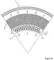
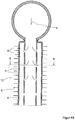
- Figure 1A shows a circular segment of a cross section through a first embodiment of the mixing device according to the invention in a radial flow reactor 1 with feeding a first fluid stream 2 via the interior of the reactor and outflow of the same at the reactor outer jacket.
- the first fluid educt flow 2 is perpendicular to a mixing device 5, comprising two rows of finned tubes 12, which are arranged on a gap and upstream of a first perforated plate 10 in the flow direction and a second perforated plate 11 is connected downstream.
- the two rows of finned tubes 12 and the upstream perforated plate 10 and the downstream perforated plate 11 are each arranged on concentric circular rings.
- the pre-mixed in the mixing device 5 reaction mixture then flows through the catalyst bed 4th
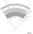
- FIG. 1B a circular segment from the cross section through a further mixing device according to the invention in a radial flow reactor is shown, but different from the illustration in FIG Figure 1A , with flow guidance of the first fluid Edukstromes 2 from outside to inside.
- the mixing device 5 comprising two rows of finned tubes 12 and an upstream perforated plate 10 and a downstream perforated plate 11, because upstream of the catalyst bed 4, along circular rings with a larger radius relative to the catalyst bed 4, respectively.
- FIGS. 2A to 2C show detailed views of finned tubes 12 with diametrically opposed openings 7 in the rib channels 8 between the ribs 9 of the finned tubes 12. This shows FIG.
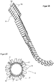
- FIG. 3 shows a perspective view of a finned tube 12 with tube 6 and helically applied rib 9, which is divided into segments 13 with the exception of a continuous rib base 14.
- FIG. 4A shows a longitudinal section through a finned tube 12 with tube 6 and ribs 9, with openings 7 in the rib passages 8 between the ribs 9 of the finned tubes 12.
- a central plug-in tube 17 is provided, with openings 18, which in the cross-sectional view in the plane BB in FIG.
- FIG. 4B can be seen, and through which the second fluid Eduktstrom 3 in the longitudinal direction of the finned tubes 12 is distributed.
- FIG. 4A one end of the finned tube 12 with annular distributor 19 for the second fluid Eduktstrom 3 is shown on the finned tubes 12.
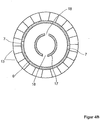
- FIG. 5A shows a longitudinal section through a radial flow reactor with supply of the first fluid Eduktstromes 2 through the central interior of the reactor and discharge on the outer jacket of the reactor first
- FIG. 5B illustrates, in addition to the annular cross-section arrangement of the catalyst bed 4 and mixing device 5, the central, through-flow of the first fluid Eduktstrom 2 cross section 20th
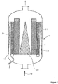
- the in longitudinal section in FIG. 5C reactor shown is analogous to the reactor FIG. 5A constructed, but with supply of the first fluid Edukstromes 2 from outside to inside and according to arrangement of the mixing device 5 outside of the catalyst bed 4th
- FIG. 6 illustrates a further preferred embodiment of a mixing device according to the invention in a reactor 1 with flow guidance of the second fluid Eduktstromes 3 from outside to inside, with displacement bodies 21 in the central interior and the reactor shell, which may preferably be as shown in the figure, parabolic.
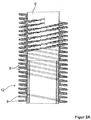
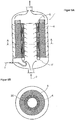
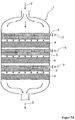
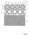
- FIG. 7A shows a longitudinal section through an axial flow reactor with tiered catalyst beds 4 and mixing devices 5 showing a longitudinal section in FIG. 7A and a section of a longitudinal section in a plane perpendicular to in FIG. 7A shown level in the FIG. 7B , The clipping in FIG.
- FIG. 7B shows two rows of finned tubes 12 with openings 7 for the exit of the second fluid Edukstromes 3 from the interior of the finned tubes 12, with additional pre-distribution of the other fluid Eduktstromes 3 via central insertion tubes 17 with openings 18, and an upstream perforated plate 10 and a downstream perforated plate 11th
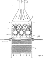
- FIG. 8 shows a longitudinal section through an experimental module for determining the quality of mixing, with two rows of finned tubes 6, with central insertion tubes 17 with openings 18, upstream perforated plate 10 and a perforated plate 11 downstream, and with a replaceable catalyst bed 4 and an extendable dipstick 22 for concentration measurement.
- the experimental modulus shown was the mixing quality of model gases, a first, consisting of nitrogen main gas stream and a second, consisting of nitrogen and 10 vol .-% carbon dioxide gas stream, with 10 times lower volume flow compared to the main gas stream determined.
- the mixing device comprised two rows of finned tubes 12 arranged in a gap, each comprising three tubes 6 having an outer diameter of 31.7 mm and helical rib 9 with 17 revolutions around the tube, which are in segments with a width of 4 mm and a height of 6.4 mm was cut.
- an upstream perforated plate 10 was arranged, with an aperture ratio of 5% and from the effluent plane of the second finned tube row at a distance of also 15 mm, a downstream perforated plate, with an opening ratio of also 5%.
- the concentration of carbon dioxide in the nitrogen stream was determined by infrared absorption with a device UNOR 6N from Maihak, Hamburg. In order to rule out calibration uncertainties, a 20 m long hose was connected to the end of the measuring rod and gas was introduced into the instrument just before the end of the tube for reference measurement. The reference measurement gave exactly 1% by volume of carbon dioxide.
- the measuring rod 22 was continuously moved through the apparatus at intervals of 2 mm samples taken and determines the concentration thereof to carbon dioxide with the above-mentioned device by infrared absorption. Measured values between 0.99% by volume of carbon dioxide and 1.01% by volume of carbon dioxide, ie deviations of maximum ⁇ 1% from the value of the reference measurement, and thus an excellent mixing quality over the entire Cross section of the apparatus, measured.
Landscapes
- Chemical & Material Sciences (AREA)
- Chemical Kinetics & Catalysis (AREA)
- Organic Chemistry (AREA)
- Physics & Mathematics (AREA)
- Fluid Mechanics (AREA)
- Devices And Processes Conducted In The Presence Of Fluids And Solid Particles (AREA)
- Physical Or Chemical Processes And Apparatus (AREA)
- Organic Low-Molecular-Weight Compounds And Preparation Thereof (AREA)
Claims (6)
- Dispositif d'incorporation par mélange (5) pour un réacteur (1) destiné à l'exécution d'une réaction entre deux produits de départ fluides (2, 3) sur un lit de catalyseur (4) avec prémélange des produits de départ fluides (2, 3) avant l'arrivée sur le lit de catalyseur en l'espace d'un temps de latence inférieur à 150 ms dans un dispositif d'incorporation par mélange (5), caractérisé en ce que le dispositif d'incorporation par mélange (5) est constitué des éléments suivants, qui sont disposés essentiellement perpendiculairement au sens d'écoulement du premier courant de produit de départ fluide (2) :- deux ou trois rangées de tubes (6), disposées successivement, avec sur la face externe de ceux-ci des générateurs de turbulence qui sont des tubes à ailettes (12), ayant un diamètre externe dans la plage comprise entre 25 et 50 mm, la deuxième rangée de tubes à ailettes étant disposée en quinconce par rapport à la première, ainsi que dans le cas de trois rangées de tubes à ailettes, la troisième rangée de tubes à ailettes étant disposée en quinconce par rapport à la deuxième rangée de tubes à ailettes, et qui resserrent jusqu'à 1/2 à 1/10 la section transversale de passage libre pour le premier courant de produit de départ fluide (2), le deuxième courant de produit de départ fluide (3) étant envoyé à travers les espaces internes des tubes (6) et injecté dans le premier courant de produit de départ fluide (2) par des ouvertures (7) dans les tubes (6), les générateurs de turbulence étant conçus sous forme d'ailettes (9) et les ouvertures (7) dans les tubes (6) débouchant dans les spires d'ailettes (8) entre les ailettes (9), et les tubes à ailettes (12) comportant par spire d'ailette (8) chaque fois deux ouvertures (7) diamétralement opposées, à la périphérie externe des tubes (6) qui les constituent, dans les spires d'ailettes (8) entre les ailettes (9), aux points présentant la plus faible distance par rapport au tube à ailettes (12) voisin respectif dans la rangée de tubes à ailettes, ainsi- qu'une tôle perforée (10) placée en amont des tubes (6) et- une tôle perforée (11) placée en aval des tubes (6), comportant des ouvertures (16) dont le diamètre est supérieur ou égal au diamètre des ouvertures (15) de la tôle perforée (10) placée en amont
et le dispositif d'homogénisation par mélange (5) présentant une profondeur de construction, c'est-à-dire une distance entre la tôle perforée (10) placée en amont et la tôle perforée (11) placée en aval, dans la plage comprise entre 100 et 200 mm. - Dispositif d'incorporation par mélange (5) pour un réacteur (1) selon la revendication 1, caractérisé en ce que le rapport d'ouverture dans la tôle perforée (10) placée en aval, défini comme la somme des surfaces libres des ouvertures (15) dans la tôle perforée par rapport à la surface totale de la section transversale perpendiculairement à la direction d'amenée du premier courant de produit de départ fluide (2) au dispositif d'incorporation par mélange (5) est ≤ 0,5, de préférence ≤ 0,3.
- Dispositif d'incorporation par mélange (5) pour un réacteur (1) selon la revendication 1 ou 2, caractérisé par un rapport de l'épaisseur de la tôle perforée au diamètre des ouvertures (15, 16) dans la tôle perforée (10, 11) dans la plage comprise entre 0,75 et 2,0.
- Dispositif d'incorporation par mélange (6) pour un réacteur (1) selon l'une quelconque des revendications 1 à 3, caractérisé en ce que la tôle perforée (11) placée en aval est disposée à une distance du plan d'écoulement de sortie des tubes à ailettes (6) correspondant à 0,5 à 2 fois le diamètre des tubes à ailettes (6) de la dernière rangée de tubes à ailettes (6).
- Dispositif d'incorporation par mélange (5) pour un réacteur (1) selon l'une quelconque des revendications 1 à 4, caractérisé par une distance de la tôlé perforée (11) placée en aval à l'entrée du mélange réactionnel dans le lit de catalyseur (4) correspondant à 5 à 20 fois le diamètre des ouvertures (16) dans la tôle perforée (11) placée en aval.
- Dispositif d'incorporation par mélange (5) pour un réacteur (1) selon l'une quelconque des revendications 1 à 5, caractérisé en ce qu'on utilise comme matériau pour les tubes (6) et les tôles perforées (10, 11) des matériaux qui sont résistants à une température élevée, à l'oxydation et éventuellement à la cémentation.
Applications Claiming Priority (3)
| Application Number | Priority Date | Filing Date | Title |
|---|---|---|---|
| DE200610060507 DE102006060507A1 (de) | 2006-12-19 | 2006-12-19 | Reaktor zur Durchführung einer Reaktion zwischen zwei fluiden Edukten an einem Katalysatorbett mit Vorvermischen der fluiden Edukte in einer Einmischvorrichtung |
| US87094506P | 2006-12-20 | 2006-12-20 | |
| EP20070848103 EP2104553B1 (fr) | 2006-12-19 | 2007-12-14 | Réacteur pour réaliser une réaction entre deux fluides sur un lit catalytique, les fluides étant prémélangés dans un dispositif de mélange |
Related Parent Applications (3)
| Application Number | Title | Priority Date | Filing Date |
|---|---|---|---|
| EP07848103.3 Division | 2007-12-14 | ||
| EP20070848103 Division-Into EP2104553B1 (fr) | 2006-12-19 | 2007-12-14 | Réacteur pour réaliser une réaction entre deux fluides sur un lit catalytique, les fluides étant prémélangés dans un dispositif de mélange |
| EP20070848103 Division EP2104553B1 (fr) | 2006-12-19 | 2007-12-14 | Réacteur pour réaliser une réaction entre deux fluides sur un lit catalytique, les fluides étant prémélangés dans un dispositif de mélange |
Publications (3)
| Publication Number | Publication Date |
|---|---|
| EP2517784A2 EP2517784A2 (fr) | 2012-10-31 |
| EP2517784A3 EP2517784A3 (fr) | 2013-05-15 |
| EP2517784B1 true EP2517784B1 (fr) | 2018-03-07 |
Family
ID=39431505
Family Applications (2)
| Application Number | Title | Priority Date | Filing Date |
|---|---|---|---|
| EP20070848103 Not-in-force EP2104553B1 (fr) | 2006-12-19 | 2007-12-14 | Réacteur pour réaliser une réaction entre deux fluides sur un lit catalytique, les fluides étant prémélangés dans un dispositif de mélange |
| EP12175556.5A Not-in-force EP2517784B1 (fr) | 2006-12-19 | 2007-12-14 | Pre-mixing device between two fluids for a reactor with a catalytic bed |
Family Applications Before (1)
| Application Number | Title | Priority Date | Filing Date |
|---|---|---|---|
| EP20070848103 Not-in-force EP2104553B1 (fr) | 2006-12-19 | 2007-12-14 | Réacteur pour réaliser une réaction entre deux fluides sur un lit catalytique, les fluides étant prémélangés dans un dispositif de mélange |
Country Status (13)
| Country | Link |
|---|---|
| US (1) | US7854906B2 (fr) |
| EP (2) | EP2104553B1 (fr) |
| JP (1) | JP5260547B2 (fr) |
| KR (1) | KR101424028B1 (fr) |
| CN (1) | CN101600494B (fr) |
| BR (1) | BRPI0720412A2 (fr) |
| DE (1) | DE102006060507A1 (fr) |
| MY (1) | MY149683A (fr) |
| RU (1) | RU2456067C2 (fr) |
| SG (1) | SG153458A1 (fr) |
| TW (1) | TWI430842B (fr) |
| WO (1) | WO2008074737A1 (fr) |
| ZA (1) | ZA200904965B (fr) |
Families Citing this family (8)
| Publication number | Priority date | Publication date | Assignee | Title |
|---|---|---|---|---|
| US7704293B2 (en) * | 2007-10-23 | 2010-04-27 | Institute Of Nuclear Energy Research | Turbulence device used for air filtration system |
| TW200936245A (en) * | 2007-10-30 | 2009-09-01 | Basf Se | Horizontal reactor for reacting a fluid feed stream with a fluid oxidant stream in the presence of a solid catalyst |
| EP2165755A1 (fr) * | 2008-09-23 | 2010-03-24 | Methanol Casale S.A. | Échangeur thermique avec éléments agencés de manière radiale pour des réacteurs chimiques isothermes |
| US9308121B2 (en) * | 2011-02-07 | 2016-04-12 | Roger Clemente | Helical air distribution system |
| EP2703076B1 (fr) * | 2012-08-29 | 2016-04-27 | Wolfgang Gerlinger | Réacteur pourvu d'une ou plusieurs conduites d'entrée de fluide et d'un dispositif de distribution desdits fluides |
| CN105623733B (zh) * | 2014-10-27 | 2017-03-01 | 中国石油化工股份有限公司 | 一种石油烃的吸附脱硫方法 |
| US10478794B1 (en) | 2019-02-26 | 2019-11-19 | Chevron Phillips Chemical Company Lp | Bi-modal radial flow reactor |
| PL429466A1 (pl) * | 2019-04-01 | 2020-10-05 | Marek Mania | Filtr szczelinowy samooczyszczający się |
Family Cites Families (19)
| Publication number | Priority date | Publication date | Assignee | Title |
|---|---|---|---|---|
| US2276307A (en) * | 1938-04-18 | 1942-03-17 | Houdry Process Corp | Catalytic converter |
| US2350644A (en) * | 1942-10-28 | 1944-06-06 | Socony Vacuum Oil Co Inc | Apparatus for catalytic conversion |
| US2417393A (en) * | 1942-11-04 | 1947-03-11 | Socony Vacuum Oil Co Inc | Apparatus for hydrocarbon reaction |
| US3214247A (en) | 1963-02-25 | 1965-10-26 | Universal Oil Prod Co | Fluid distributing means for packed chambers |
| FR2019968B1 (fr) | 1968-10-04 | 1974-11-15 | Escoa Corp | |
| GB1328302A (en) * | 1970-06-25 | 1973-08-30 | Escoa Fintube Corp | Segmented finned tube and its method of manufacture |
| JPS5932178B2 (ja) * | 1981-11-06 | 1984-08-07 | 永岡金網株式会社 | 多孔管内包式スクリ−ン筒 |
| JPS5959242A (ja) * | 1982-09-28 | 1984-04-05 | Toyo Eng Corp | 反応方法およびそのための反応器 |
| US5462719A (en) * | 1994-06-08 | 1995-10-31 | Atlantic Richfield Company | Method and apparatus for mixing and distributing fluids in a reactor |
| WO1996007712A1 (fr) * | 1994-09-02 | 1996-03-14 | PUSCHKAREW, Aleksander Wasiliewitsch | Procede de reformage catalytique et reacteur |
| AU4859099A (en) * | 1998-07-09 | 2000-02-01 | Washington Group International Inc. | Radial flow reactor |
| JP3858132B2 (ja) * | 1999-03-29 | 2006-12-13 | 日立造船株式会社 | 排ガス脱硝システムのアンモニア注入装置 |
| US6772830B1 (en) * | 1999-07-21 | 2004-08-10 | Stone & Webster, Inc. | Enhanced crossflow heat transfer |
| EP1080780B1 (fr) * | 1999-08-31 | 2007-08-01 | Nippon Shokubai Co., Ltd. | Réacteur pour l'oxydation catalytique en phase gazeuse |
| US7316804B2 (en) * | 2001-08-02 | 2008-01-08 | Ineos Usa Llc | Flow reactors for chemical conversions with heterogeneous catalysts |
| RU30289U1 (ru) * | 2003-03-27 | 2003-06-27 | Общество с ограниченной ответственностью Научно-производственная компания "Кедр - 89" | Реактор для каталитических процессов |
| DE10359744A1 (de) * | 2003-12-19 | 2005-07-14 | Uhde Gmbh | Verfahren und Vorrichtung zum Eindüsen von Sauerstoff in einen Synthesereaktor |
| DE102004024957A1 (de) | 2004-05-22 | 2005-12-22 | Uhde Gmbh | Verfahren und Vorrichtung zum Eindüsen von Sauerstoff in ein einen Synthesereaktor durchströmendes Reaktionsgas |
| DE102006060509A1 (de) * | 2006-12-19 | 2008-06-26 | Basf Se | Reaktor zur Durchführung einer kontinuierlichen Oxidehydrierung sowie Verfahren |
-
2006
- 2006-12-19 DE DE200610060507 patent/DE102006060507A1/de not_active Withdrawn
-
2007
- 2007-12-14 BR BRPI0720412-4A2A patent/BRPI0720412A2/pt not_active IP Right Cessation
- 2007-12-14 RU RU2009127502/05A patent/RU2456067C2/ru not_active IP Right Cessation
- 2007-12-14 SG SG200904205A patent/SG153458A1/en unknown
- 2007-12-14 MY MYPI20092537A patent/MY149683A/en unknown
- 2007-12-14 KR KR1020097014950A patent/KR101424028B1/ko not_active IP Right Cessation
- 2007-12-14 EP EP20070848103 patent/EP2104553B1/fr not_active Not-in-force
- 2007-12-14 CN CN2007800510248A patent/CN101600494B/zh not_active Expired - Fee Related
- 2007-12-14 WO PCT/EP2007/063951 patent/WO2008074737A1/fr active Application Filing
- 2007-12-14 EP EP12175556.5A patent/EP2517784B1/fr not_active Not-in-force
- 2007-12-14 JP JP2009542012A patent/JP5260547B2/ja not_active Expired - Fee Related
- 2007-12-18 US US11/959,008 patent/US7854906B2/en not_active Expired - Fee Related
- 2007-12-19 TW TW96148759A patent/TWI430842B/zh not_active IP Right Cessation
-
2009
- 2009-07-16 ZA ZA200904965A patent/ZA200904965B/xx unknown
Non-Patent Citations (1)
| Title |
|---|
| None * |
Also Published As
| Publication number | Publication date |
|---|---|
| DE102006060507A1 (de) | 2008-06-26 |
| RU2456067C2 (ru) | 2012-07-20 |
| TW200909058A (en) | 2009-03-01 |
| EP2104553B1 (fr) | 2014-03-26 |
| CN101600494B (zh) | 2013-01-30 |
| KR20090091234A (ko) | 2009-08-26 |
| EP2517784A2 (fr) | 2012-10-31 |
| KR101424028B1 (ko) | 2014-07-28 |
| MY149683A (en) | 2013-09-30 |
| JP2010513005A (ja) | 2010-04-30 |
| ZA200904965B (en) | 2010-09-29 |
| CN101600494A (zh) | 2009-12-09 |
| US20080145285A1 (en) | 2008-06-19 |
| US7854906B2 (en) | 2010-12-21 |
| TWI430842B (zh) | 2014-03-21 |
| BRPI0720412A2 (pt) | 2013-12-31 |
| RU2009127502A (ru) | 2011-01-27 |
| EP2517784A3 (fr) | 2013-05-15 |
| SG153458A1 (en) | 2009-07-29 |
| JP5260547B2 (ja) | 2013-08-14 |
| EP2104553A1 (fr) | 2009-09-30 |
| WO2008074737A1 (fr) | 2008-06-26 |
Similar Documents
| Publication | Publication Date | Title |
|---|---|---|
| EP2517784B1 (fr) | Pre-mixing device between two fluids for a reactor with a catalytic bed | |
| EP2101900B1 (fr) | Réacteur pour réaliser une déshydrogénation oxydante en continu et procédé associé | |
| EP2379216B1 (fr) | Réacteur et procédé de pröparation du phosgène | |
| EP0396650B1 (fr) | Dispositif de mise en uvre de reactions catalysees | |
| DE10031347A1 (de) | Reaktor mit Wärmetauscherplatten | |
| DE69825408T2 (de) | Wärmeaustauscher und dessen gebrauchsverfahren | |
| DE2439144B2 (de) | Vorrichtung zum Verteilen strömender Medien von einem Strömungsquerschnitt auf einen davon verschiedenen Strömungsquerschnitt | |
| DE2205371A1 (de) | Mischeinrichtung | |
| EP0526393A1 (fr) | dispositif d'immixtion | |
| WO2003072237A1 (fr) | Reacteur et procede de production de phosgene | |
| DE2203648B2 (de) | Vorrichtung zum einleiten eines ersten gasstromes in einen zweiten | |
| DE60108869T2 (de) | Rohrreaktor mit gasinjektor für katalytische reaktionen in der gasphase | |
| WO2009056488A1 (fr) | Réacteur horizontal pour transformer un courant d'éduit fluide avec un courant d'oxydation fluide en présence d'un catalyseur solide | |
| EP2915581B1 (fr) | Mélangeur statique | |
| WO2005075064A1 (fr) | Reacteur pourvu d'une zone d'echange de chaleur possedant un insert | |
| EP2252567B1 (fr) | Procede et dispositif d'oxydation thermique partielle d'hydrocarbures | |
| EP2680957B1 (fr) | Procédé et dispositif de mélange de deux courants de fluide | |
| EP1493475B1 (fr) | Réacteur pour des réactions gaz/liquide ou gaz/liquide/solide | |
| EP1486728A2 (fr) | Brûleur à récupération et récupérateur | |
| DE3042090C2 (fr) | ||
| EP3038742A1 (fr) | Dispositif et procédé de production d'acétylène et de gaz de synthèse | |
| DE10032302A1 (de) | Rohrreaktor mit Einrichtungen zur Wärmeübertragung | |
| WO2021156092A1 (fr) | Procédé et réacteur pour la production de phosgène | |
| EP3972934A1 (fr) | Procédé et réacteur de fabrication de phosgène | |
| EP3153465A1 (fr) | Reformateur destine a la fabrication d'un gaz de synthese |
Legal Events
| Date | Code | Title | Description |
|---|---|---|---|
| PUAI | Public reference made under article 153(3) epc to a published international application that has entered the european phase |
Free format text: ORIGINAL CODE: 0009012 |
|
| AC | Divisional application: reference to earlier application |
Ref document number: 2104553 Country of ref document: EP Kind code of ref document: P |
|
| AK | Designated contracting states |
Kind code of ref document: A2 Designated state(s): AT BE BG CH CY CZ DE DK EE ES FI FR GB GR HU IE IS IT LI LT LU LV MC MT NL PL PT RO SE SI SK TR |
|
| PUAL | Search report despatched |
Free format text: ORIGINAL CODE: 0009013 |
|
| AK | Designated contracting states |
Kind code of ref document: A3 Designated state(s): AT BE BG CH CY CZ DE DK EE ES FI FR GB GR HU IE IS IT LI LT LU LV MC MT NL PL PT RO SE SI SK TR |
|
| RIC1 | Information provided on ipc code assigned before grant |
Ipc: B01J 8/02 20060101ALI20130409BHEP Ipc: B01J 8/04 20060101ALI20130409BHEP Ipc: B01F 5/04 20060101AFI20130409BHEP Ipc: B01J 8/00 20060101ALI20130409BHEP |
|
| 17P | Request for examination filed |
Effective date: 20131115 |
|
| RBV | Designated contracting states (corrected) |
Designated state(s): AT BE BG CH CY CZ DE DK EE ES FI FR GB GR HU IE IS IT LI LT LU LV MC MT NL PL PT RO SE SI SK TR |
|
| GRAP | Despatch of communication of intention to grant a patent |
Free format text: ORIGINAL CODE: EPIDOSNIGR1 |
|
| INTG | Intention to grant announced |
Effective date: 20170705 |
|
| GRAJ | Information related to disapproval of communication of intention to grant by the applicant or resumption of examination proceedings by the epo deleted |
Free format text: ORIGINAL CODE: EPIDOSDIGR1 |
|
| GRAP | Despatch of communication of intention to grant a patent |
Free format text: ORIGINAL CODE: EPIDOSNIGR1 |
|
| INTC | Intention to grant announced (deleted) | ||
| INTG | Intention to grant announced |
Effective date: 20170927 |
|
| GRAS | Grant fee paid |
Free format text: ORIGINAL CODE: EPIDOSNIGR3 |
|
| GRAA | (expected) grant |
Free format text: ORIGINAL CODE: 0009210 |
|
| AC | Divisional application: reference to earlier application |
Ref document number: 2104553 Country of ref document: EP Kind code of ref document: P |
|
| AK | Designated contracting states |
Kind code of ref document: B1 Designated state(s): AT BE BG CH CY CZ DE DK EE ES FI FR GB GR HU IE IS IT LI LT LU LV MC MT NL PL PT RO SE SI SK TR |
|
| REG | Reference to a national code |
Ref country code: GB Ref legal event code: FG4D Free format text: NOT ENGLISH |
|
| REG | Reference to a national code |
Ref country code: CH Ref legal event code: EP Ref country code: AT Ref legal event code: REF Ref document number: 975952 Country of ref document: AT Kind code of ref document: T Effective date: 20180315 |
|
| REG | Reference to a national code |
Ref country code: DE Ref legal event code: R096 Ref document number: 502007016101 Country of ref document: DE |
|
| REG | Reference to a national code |
Ref country code: IE Ref legal event code: FG4D Free format text: LANGUAGE OF EP DOCUMENT: GERMAN |
|
| REG | Reference to a national code |
Ref country code: NL Ref legal event code: MP Effective date: 20180307 |
|
| REG | Reference to a national code |
Ref country code: LT Ref legal event code: MG4D |
|
| PG25 | Lapsed in a contracting state [announced via postgrant information from national office to epo] |
Ref country code: ES Free format text: LAPSE BECAUSE OF FAILURE TO SUBMIT A TRANSLATION OF THE DESCRIPTION OR TO PAY THE FEE WITHIN THE PRESCRIBED TIME-LIMIT Effective date: 20180307 Ref country code: CY Free format text: LAPSE BECAUSE OF FAILURE TO SUBMIT A TRANSLATION OF THE DESCRIPTION OR TO PAY THE FEE WITHIN THE PRESCRIBED TIME-LIMIT Effective date: 20180307 Ref country code: LT Free format text: LAPSE BECAUSE OF FAILURE TO SUBMIT A TRANSLATION OF THE DESCRIPTION OR TO PAY THE FEE WITHIN THE PRESCRIBED TIME-LIMIT Effective date: 20180307 Ref country code: FI Free format text: LAPSE BECAUSE OF FAILURE TO SUBMIT A TRANSLATION OF THE DESCRIPTION OR TO PAY THE FEE WITHIN THE PRESCRIBED TIME-LIMIT Effective date: 20180307 |
|
| PG25 | Lapsed in a contracting state [announced via postgrant information from national office to epo] |
Ref country code: GR Free format text: LAPSE BECAUSE OF FAILURE TO SUBMIT A TRANSLATION OF THE DESCRIPTION OR TO PAY THE FEE WITHIN THE PRESCRIBED TIME-LIMIT Effective date: 20180608 Ref country code: BG Free format text: LAPSE BECAUSE OF FAILURE TO SUBMIT A TRANSLATION OF THE DESCRIPTION OR TO PAY THE FEE WITHIN THE PRESCRIBED TIME-LIMIT Effective date: 20180607 Ref country code: LV Free format text: LAPSE BECAUSE OF FAILURE TO SUBMIT A TRANSLATION OF THE DESCRIPTION OR TO PAY THE FEE WITHIN THE PRESCRIBED TIME-LIMIT Effective date: 20180307 Ref country code: SE Free format text: LAPSE BECAUSE OF FAILURE TO SUBMIT A TRANSLATION OF THE DESCRIPTION OR TO PAY THE FEE WITHIN THE PRESCRIBED TIME-LIMIT Effective date: 20180307 |
|
| PG25 | Lapsed in a contracting state [announced via postgrant information from national office to epo] |
Ref country code: MT Free format text: LAPSE BECAUSE OF FAILURE TO SUBMIT A TRANSLATION OF THE DESCRIPTION OR TO PAY THE FEE WITHIN THE PRESCRIBED TIME-LIMIT Effective date: 20180307 |
|
| PG25 | Lapsed in a contracting state [announced via postgrant information from national office to epo] |
Ref country code: RO Free format text: LAPSE BECAUSE OF FAILURE TO SUBMIT A TRANSLATION OF THE DESCRIPTION OR TO PAY THE FEE WITHIN THE PRESCRIBED TIME-LIMIT Effective date: 20180307 Ref country code: PL Free format text: LAPSE BECAUSE OF FAILURE TO SUBMIT A TRANSLATION OF THE DESCRIPTION OR TO PAY THE FEE WITHIN THE PRESCRIBED TIME-LIMIT Effective date: 20180307 Ref country code: NL Free format text: LAPSE BECAUSE OF FAILURE TO SUBMIT A TRANSLATION OF THE DESCRIPTION OR TO PAY THE FEE WITHIN THE PRESCRIBED TIME-LIMIT Effective date: 20180307 Ref country code: IT Free format text: LAPSE BECAUSE OF FAILURE TO SUBMIT A TRANSLATION OF THE DESCRIPTION OR TO PAY THE FEE WITHIN THE PRESCRIBED TIME-LIMIT Effective date: 20180307 Ref country code: EE Free format text: LAPSE BECAUSE OF FAILURE TO SUBMIT A TRANSLATION OF THE DESCRIPTION OR TO PAY THE FEE WITHIN THE PRESCRIBED TIME-LIMIT Effective date: 20180307 |
|
| PG25 | Lapsed in a contracting state [announced via postgrant information from national office to epo] |
Ref country code: CZ Free format text: LAPSE BECAUSE OF FAILURE TO SUBMIT A TRANSLATION OF THE DESCRIPTION OR TO PAY THE FEE WITHIN THE PRESCRIBED TIME-LIMIT Effective date: 20180307 Ref country code: SK Free format text: LAPSE BECAUSE OF FAILURE TO SUBMIT A TRANSLATION OF THE DESCRIPTION OR TO PAY THE FEE WITHIN THE PRESCRIBED TIME-LIMIT Effective date: 20180307 |
|
| REG | Reference to a national code |
Ref country code: DE Ref legal event code: R097 Ref document number: 502007016101 Country of ref document: DE |
|
| PG25 | Lapsed in a contracting state [announced via postgrant information from national office to epo] |
Ref country code: PT Free format text: LAPSE BECAUSE OF FAILURE TO SUBMIT A TRANSLATION OF THE DESCRIPTION OR TO PAY THE FEE WITHIN THE PRESCRIBED TIME-LIMIT Effective date: 20180709 |
|
| PLBE | No opposition filed within time limit |
Free format text: ORIGINAL CODE: 0009261 |
|
| STAA | Information on the status of an ep patent application or granted ep patent |
Free format text: STATUS: NO OPPOSITION FILED WITHIN TIME LIMIT |
|
| PG25 | Lapsed in a contracting state [announced via postgrant information from national office to epo] |
Ref country code: DK Free format text: LAPSE BECAUSE OF FAILURE TO SUBMIT A TRANSLATION OF THE DESCRIPTION OR TO PAY THE FEE WITHIN THE PRESCRIBED TIME-LIMIT Effective date: 20180307 |
|
| 26N | No opposition filed |
Effective date: 20181210 |
|
| PG25 | Lapsed in a contracting state [announced via postgrant information from national office to epo] |
Ref country code: SI Free format text: LAPSE BECAUSE OF FAILURE TO SUBMIT A TRANSLATION OF THE DESCRIPTION OR TO PAY THE FEE WITHIN THE PRESCRIBED TIME-LIMIT Effective date: 20180307 |
|
| REG | Reference to a national code |
Ref country code: DE Ref legal event code: R119 Ref document number: 502007016101 Country of ref document: DE |
|
| REG | Reference to a national code |
Ref country code: CH Ref legal event code: PL |
|
| GBPC | Gb: european patent ceased through non-payment of renewal fee |
Effective date: 20181214 |
|
| PG25 | Lapsed in a contracting state [announced via postgrant information from national office to epo] |
Ref country code: MC Free format text: LAPSE BECAUSE OF FAILURE TO SUBMIT A TRANSLATION OF THE DESCRIPTION OR TO PAY THE FEE WITHIN THE PRESCRIBED TIME-LIMIT Effective date: 20180307 Ref country code: LU Free format text: LAPSE BECAUSE OF NON-PAYMENT OF DUE FEES Effective date: 20181214 |
|
| REG | Reference to a national code |
Ref country code: IE Ref legal event code: MM4A |
|
| REG | Reference to a national code |
Ref country code: BE Ref legal event code: MM Effective date: 20181231 |
|
| PG25 | Lapsed in a contracting state [announced via postgrant information from national office to epo] |
Ref country code: FR Free format text: LAPSE BECAUSE OF NON-PAYMENT OF DUE FEES Effective date: 20181231 Ref country code: DE Free format text: LAPSE BECAUSE OF NON-PAYMENT OF DUE FEES Effective date: 20190702 Ref country code: IE Free format text: LAPSE BECAUSE OF NON-PAYMENT OF DUE FEES Effective date: 20181214 |
|
| PG25 | Lapsed in a contracting state [announced via postgrant information from national office to epo] |
Ref country code: BE Free format text: LAPSE BECAUSE OF NON-PAYMENT OF DUE FEES Effective date: 20181231 |
|
| PG25 | Lapsed in a contracting state [announced via postgrant information from national office to epo] |
Ref country code: GB Free format text: LAPSE BECAUSE OF NON-PAYMENT OF DUE FEES Effective date: 20181214 Ref country code: LI Free format text: LAPSE BECAUSE OF NON-PAYMENT OF DUE FEES Effective date: 20181231 Ref country code: CH Free format text: LAPSE BECAUSE OF NON-PAYMENT OF DUE FEES Effective date: 20181231 |
|
| REG | Reference to a national code |
Ref country code: AT Ref legal event code: MM01 Ref document number: 975952 Country of ref document: AT Kind code of ref document: T Effective date: 20181214 |
|
| PG25 | Lapsed in a contracting state [announced via postgrant information from national office to epo] |
Ref country code: TR Free format text: LAPSE BECAUSE OF FAILURE TO SUBMIT A TRANSLATION OF THE DESCRIPTION OR TO PAY THE FEE WITHIN THE PRESCRIBED TIME-LIMIT Effective date: 20180307 |
|
| PG25 | Lapsed in a contracting state [announced via postgrant information from national office to epo] |
Ref country code: AT Free format text: LAPSE BECAUSE OF NON-PAYMENT OF DUE FEES Effective date: 20181214 |
|
| PG25 | Lapsed in a contracting state [announced via postgrant information from national office to epo] |
Ref country code: HU Free format text: LAPSE BECAUSE OF FAILURE TO SUBMIT A TRANSLATION OF THE DESCRIPTION OR TO PAY THE FEE WITHIN THE PRESCRIBED TIME-LIMIT; INVALID AB INITIO Effective date: 20071214 |
|
| PG25 | Lapsed in a contracting state [announced via postgrant information from national office to epo] |
Ref country code: IS Free format text: LAPSE BECAUSE OF FAILURE TO SUBMIT A TRANSLATION OF THE DESCRIPTION OR TO PAY THE FEE WITHIN THE PRESCRIBED TIME-LIMIT Effective date: 20180707 |