EP2703076B1 - Réacteur pourvu d'une ou plusieurs conduites d'entrée de fluide et d'un dispositif de distribution desdits fluides - Google Patents
Réacteur pourvu d'une ou plusieurs conduites d'entrée de fluide et d'un dispositif de distribution desdits fluides Download PDFInfo
- Publication number
- EP2703076B1 EP2703076B1 EP13182077.1A EP13182077A EP2703076B1 EP 2703076 B1 EP2703076 B1 EP 2703076B1 EP 13182077 A EP13182077 A EP 13182077A EP 2703076 B1 EP2703076 B1 EP 2703076B1
- Authority
- EP
- European Patent Office
- Prior art keywords
- reactor
- range
- essentially planar
- flow direction
- main flow
- Prior art date
- Legal status (The legal status is an assumption and is not a legal conclusion. Google has not performed a legal analysis and makes no representation as to the accuracy of the status listed.)
- Active
Links
- 239000012530 fluid Substances 0.000 title claims description 34
- 238000009826 distribution Methods 0.000 title description 9
- 238000006243 chemical reaction Methods 0.000 claims description 21
- WSFSSNUMVMOOMR-UHFFFAOYSA-N Formaldehyde Chemical compound O=C WSFSSNUMVMOOMR-UHFFFAOYSA-N 0.000 claims description 6
- 238000004519 manufacturing process Methods 0.000 claims description 5
- ATUOYWHBWRKTHZ-UHFFFAOYSA-N Propane Chemical compound CCC ATUOYWHBWRKTHZ-UHFFFAOYSA-N 0.000 claims description 4
- 238000006356 dehydrogenation reaction Methods 0.000 claims description 4
- 238000000746 purification Methods 0.000 claims description 3
- 238000011144 upstream manufacturing Methods 0.000 claims description 3
- GRYLNZFGIOXLOG-UHFFFAOYSA-N Nitric acid Chemical compound O[N+]([O-])=O GRYLNZFGIOXLOG-UHFFFAOYSA-N 0.000 claims description 2
- 239000001273 butane Substances 0.000 claims description 2
- IJDNQMDRQITEOD-UHFFFAOYSA-N n-butane Chemical compound CCCC IJDNQMDRQITEOD-UHFFFAOYSA-N 0.000 claims description 2
- OFBQJSOFQDEBGM-UHFFFAOYSA-N n-pentane Natural products CCCCC OFBQJSOFQDEBGM-UHFFFAOYSA-N 0.000 claims description 2
- 229910017604 nitric acid Inorganic materials 0.000 claims description 2
- 239000001294 propane Substances 0.000 claims description 2
- 238000009827 uniform distribution Methods 0.000 description 12
- 239000003054 catalyst Substances 0.000 description 7
- 239000007789 gas Substances 0.000 description 6
- 230000000052 comparative effect Effects 0.000 description 5
- 239000000463 material Substances 0.000 description 5
- VYPSYNLAJGMNEJ-UHFFFAOYSA-N Silicium dioxide Chemical compound O=[Si]=O VYPSYNLAJGMNEJ-UHFFFAOYSA-N 0.000 description 4
- 238000005259 measurement Methods 0.000 description 4
- 238000002485 combustion reaction Methods 0.000 description 3
- 229910052878 cordierite Inorganic materials 0.000 description 3
- JSKIRARMQDRGJZ-UHFFFAOYSA-N dimagnesium dioxido-bis[(1-oxido-3-oxo-2,4,6,8,9-pentaoxa-1,3-disila-5,7-dialuminabicyclo[3.3.1]nonan-7-yl)oxy]silane Chemical compound [Mg++].[Mg++].[O-][Si]([O-])(O[Al]1O[Al]2O[Si](=O)O[Si]([O-])(O1)O2)O[Al]1O[Al]2O[Si](=O)O[Si]([O-])(O1)O2 JSKIRARMQDRGJZ-UHFFFAOYSA-N 0.000 description 3
- 230000000694 effects Effects 0.000 description 3
- 239000011541 reaction mixture Substances 0.000 description 3
- PNEYBMLMFCGWSK-UHFFFAOYSA-N aluminium oxide Inorganic materials [O-2].[O-2].[O-2].[Al+3].[Al+3] PNEYBMLMFCGWSK-UHFFFAOYSA-N 0.000 description 2
- 239000000919 ceramic Substances 0.000 description 2
- 229910010293 ceramic material Inorganic materials 0.000 description 2
- 238000000576 coating method Methods 0.000 description 2
- 229930195733 hydrocarbon Natural products 0.000 description 2
- 150000002430 hydrocarbons Chemical class 0.000 description 2
- 239000002245 particle Substances 0.000 description 2
- 239000000523 sample Substances 0.000 description 2
- 239000000377 silicon dioxide Substances 0.000 description 2
- 239000000126 substance Substances 0.000 description 2
- 238000012546 transfer Methods 0.000 description 2
- 230000007704 transition Effects 0.000 description 2
- 239000004215 Carbon black (E152) Substances 0.000 description 1
- -1 as usual Substances 0.000 description 1
- QVGXLLKOCUKJST-UHFFFAOYSA-N atomic oxygen Chemical compound [O] QVGXLLKOCUKJST-UHFFFAOYSA-N 0.000 description 1
- TZCXTZWJZNENPQ-UHFFFAOYSA-L barium sulfate Chemical compound [Ba+2].[O-]S([O-])(=O)=O TZCXTZWJZNENPQ-UHFFFAOYSA-L 0.000 description 1
- 238000009530 blood pressure measurement Methods 0.000 description 1
- 239000012876 carrier material Substances 0.000 description 1
- 230000015556 catabolic process Effects 0.000 description 1
- 230000003197 catalytic effect Effects 0.000 description 1
- 238000012824 chemical production Methods 0.000 description 1
- 239000011248 coating agent Substances 0.000 description 1
- 238000006731 degradation reaction Methods 0.000 description 1
- KZHJGOXRZJKJNY-UHFFFAOYSA-N dioxosilane;oxo(oxoalumanyloxy)alumane Chemical compound O=[Si]=O.O=[Si]=O.O=[Al]O[Al]=O.O=[Al]O[Al]=O.O=[Al]O[Al]=O KZHJGOXRZJKJNY-UHFFFAOYSA-N 0.000 description 1
- 238000002474 experimental method Methods 0.000 description 1
- 230000002349 favourable effect Effects 0.000 description 1
- 239000006260 foam Substances 0.000 description 1
- 239000000446 fuel Substances 0.000 description 1
- 239000002638 heterogeneous catalyst Substances 0.000 description 1
- 238000009434 installation Methods 0.000 description 1
- 239000007788 liquid Substances 0.000 description 1
- 239000000395 magnesium oxide Substances 0.000 description 1
- CPLXHLVBOLITMK-UHFFFAOYSA-N magnesium oxide Inorganic materials [Mg]=O CPLXHLVBOLITMK-UHFFFAOYSA-N 0.000 description 1
- AXZKOIWUVFPNLO-UHFFFAOYSA-N magnesium;oxygen(2-) Chemical compound [O-2].[Mg+2] AXZKOIWUVFPNLO-UHFFFAOYSA-N 0.000 description 1
- 238000007726 management method Methods 0.000 description 1
- 229910052751 metal Inorganic materials 0.000 description 1
- 239000002184 metal Substances 0.000 description 1
- 150000002739 metals Chemical class 0.000 description 1
- 238000000034 method Methods 0.000 description 1
- 239000000203 mixture Substances 0.000 description 1
- 238000000465 moulding Methods 0.000 description 1
- 229910052863 mullite Inorganic materials 0.000 description 1
- 229910000510 noble metal Inorganic materials 0.000 description 1
- 239000001301 oxygen Substances 0.000 description 1
- 229910052760 oxygen Inorganic materials 0.000 description 1
- 238000012856 packing Methods 0.000 description 1
- 239000000376 reactant Substances 0.000 description 1
- 239000012429 reaction media Substances 0.000 description 1
- 238000007086 side reaction Methods 0.000 description 1
- HBMJWWWQQXIZIP-UHFFFAOYSA-N silicon carbide Chemical compound [Si+]#[C-] HBMJWWWQQXIZIP-UHFFFAOYSA-N 0.000 description 1
- 229910010271 silicon carbide Inorganic materials 0.000 description 1
- 230000002269 spontaneous effect Effects 0.000 description 1
Images

Classifications
-
- B—PERFORMING OPERATIONS; TRANSPORTING
- B01—PHYSICAL OR CHEMICAL PROCESSES OR APPARATUS IN GENERAL
- B01J—CHEMICAL OR PHYSICAL PROCESSES, e.g. CATALYSIS OR COLLOID CHEMISTRY; THEIR RELEVANT APPARATUS
- B01J8/00—Chemical or physical processes in general, conducted in the presence of fluids and solid particles; Apparatus for such processes
- B01J8/02—Chemical or physical processes in general, conducted in the presence of fluids and solid particles; Apparatus for such processes with stationary particles, e.g. in fixed beds
- B01J8/0278—Feeding reactive fluids
-
- B—PERFORMING OPERATIONS; TRANSPORTING
- B01—PHYSICAL OR CHEMICAL PROCESSES OR APPARATUS IN GENERAL
- B01J—CHEMICAL OR PHYSICAL PROCESSES, e.g. CATALYSIS OR COLLOID CHEMISTRY; THEIR RELEVANT APPARATUS
- B01J19/00—Chemical, physical or physico-chemical processes in general; Their relevant apparatus
- B01J19/0053—Details of the reactor
- B01J19/006—Baffles
-
- B—PERFORMING OPERATIONS; TRANSPORTING
- B01—PHYSICAL OR CHEMICAL PROCESSES OR APPARATUS IN GENERAL
- B01J—CHEMICAL OR PHYSICAL PROCESSES, e.g. CATALYSIS OR COLLOID CHEMISTRY; THEIR RELEVANT APPARATUS
- B01J19/00—Chemical, physical or physico-chemical processes in general; Their relevant apparatus
- B01J19/24—Stationary reactors without moving elements inside
- B01J19/2415—Tubular reactors
- B01J19/2425—Tubular reactors in parallel
-
- B—PERFORMING OPERATIONS; TRANSPORTING
- B01—PHYSICAL OR CHEMICAL PROCESSES OR APPARATUS IN GENERAL
- B01J—CHEMICAL OR PHYSICAL PROCESSES, e.g. CATALYSIS OR COLLOID CHEMISTRY; THEIR RELEVANT APPARATUS
- B01J19/00—Chemical, physical or physico-chemical processes in general; Their relevant apparatus
- B01J19/24—Stationary reactors without moving elements inside
- B01J19/248—Reactors comprising multiple separated flow channels
- B01J19/2485—Monolithic reactors
-
- B—PERFORMING OPERATIONS; TRANSPORTING
- B01—PHYSICAL OR CHEMICAL PROCESSES OR APPARATUS IN GENERAL
- B01J—CHEMICAL OR PHYSICAL PROCESSES, e.g. CATALYSIS OR COLLOID CHEMISTRY; THEIR RELEVANT APPARATUS
- B01J19/00—Chemical, physical or physico-chemical processes in general; Their relevant apparatus
- B01J19/30—Loose or shaped packing elements, e.g. Raschig rings or Berl saddles, for pouring into the apparatus for mass or heat transfer
-
- B—PERFORMING OPERATIONS; TRANSPORTING
- B01—PHYSICAL OR CHEMICAL PROCESSES OR APPARATUS IN GENERAL
- B01J—CHEMICAL OR PHYSICAL PROCESSES, e.g. CATALYSIS OR COLLOID CHEMISTRY; THEIR RELEVANT APPARATUS
- B01J19/00—Chemical, physical or physico-chemical processes in general; Their relevant apparatus
- B01J19/32—Packing elements in the form of grids or built-up elements for forming a unit or module inside the apparatus for mass or heat transfer
-
- B—PERFORMING OPERATIONS; TRANSPORTING
- B01—PHYSICAL OR CHEMICAL PROCESSES OR APPARATUS IN GENERAL
- B01J—CHEMICAL OR PHYSICAL PROCESSES, e.g. CATALYSIS OR COLLOID CHEMISTRY; THEIR RELEVANT APPARATUS
- B01J2208/00—Processes carried out in the presence of solid particles; Reactors therefor
- B01J2208/00008—Controlling the process
- B01J2208/00725—Mathematical modelling
-
- B—PERFORMING OPERATIONS; TRANSPORTING
- B01—PHYSICAL OR CHEMICAL PROCESSES OR APPARATUS IN GENERAL
- B01J—CHEMICAL OR PHYSICAL PROCESSES, e.g. CATALYSIS OR COLLOID CHEMISTRY; THEIR RELEVANT APPARATUS
- B01J2208/00—Processes carried out in the presence of solid particles; Reactors therefor
- B01J2208/00796—Details of the reactor or of the particulate material
- B01J2208/00823—Mixing elements
- B01J2208/00831—Stationary elements
- B01J2208/00849—Stationary elements outside the bed, e.g. baffles
-
- B—PERFORMING OPERATIONS; TRANSPORTING
- B01—PHYSICAL OR CHEMICAL PROCESSES OR APPARATUS IN GENERAL
- B01J—CHEMICAL OR PHYSICAL PROCESSES, e.g. CATALYSIS OR COLLOID CHEMISTRY; THEIR RELEVANT APPARATUS
- B01J2208/00—Processes carried out in the presence of solid particles; Reactors therefor
- B01J2208/00796—Details of the reactor or of the particulate material
- B01J2208/00938—Flow distribution elements
Definitions
- the invention relates to a reactor having one or more supply lines for one or more fluid streams, with internals, the heat or dissipate and / or takes place in the reactor, a chemical reaction, arranged in the main flow direction in front of the internals in the reactor uniform distribution device, and a Use of the reactor.
- Reactors that is, apparatus in which a chemical reaction takes place, are increasingly burdened with higher volume flows in order to increase their efficiency.
- Reactors that is, apparatus in which a chemical reaction takes place
- uniform distribution submissions lead to increased pressure losses, with correspondingly higher capital and operating costs, in particular for the delivery of the fluid.
- a reactor in the present case, as usual, an apparatus understood in which a chemical reaction, ie one or more chemical reactions, takes place.
- the reactor is in particular formed predominantly cylindrical, wherein a cylindrical main part of the reactor at least at the reactor inlet, preferably at both ends of the same each with a reactor hood closes, which may be frusto-conically tapered or dome-shaped or may be expanded differently, for. B. in the form of a spontaneous increase in the diameter.
- the base of the cylinder is in particular circular. But it can also elliptical, polygonal, z. B. triangular, square or rectangular.
- the main flow direction is parallel to the longitudinal axis of the cylinder, from the feed to the discharge of the fluid streams.
- the reactor may advantageously be arranged transversely, that is to say with a horizontal longitudinal axis, or also standing, that is to say with a vertical longitudinal axis, or in any spatial direction.
- One or more feed lines for one or more fluid streams are provided at one end of the reactor and one or more, preferably a discharge line for the reaction mixture at the other end of the reactor.
- gases or liquids or multiphase mixtures thereof understood As fluids, as usual, gases or liquids or multiphase mixtures thereof understood.
- the one or more fluid streams are reactant streams which participate in the chemical reaction in the reactor.
- one or more further fluid streams can be supplied, which are inert under the reaction conditions in the reactor.
- the one or more fluid streams each have a temperature of 200 ° C or greater.
- the feed lines having cross-sectional areas A i through which the one or more fluid streams at one end are fed to the reactor have an overall cross-sectional area ⁇ A i , where i is the feed variable for the feed lines and where ⁇ A i is less than the maximum cross-sectional area A R is the reactor.
- cross-sectional area is meant a surface perpendicular to the main flow direction through the reactor.
- the maximum or maximum cross-sectional area A R of the reactor corresponds in the case of a substantially cylindrical reactor to the cross-sectional area of the reactor, ie, in the case of a cylindrical reactor, to the base area of the cylinder.
- the maximum cross-sectional area A R of the reactor is preferably in the range from 0.01 to 10.0 m 2 , in particular in the range from 1 to 2 m 2 .
- the ratio of reactor cross-sectional area to the total cross-sectional area of the leads A R / ⁇ A i is between 2 and 25, preferably between 3 and 10.
- the ratio of reactor cross-sectional area to the total cross-sectional area of the leads A R / ⁇ A i is between 25 and 10,000, preferably between 25 and 1,000, preferably between 50 and 250.
- heat may be added to or removed from the reactor with one or more of the three or more substantially planar components or with other internals.
- the chemical reaction may take place on the surface of the internals, in beds which may be incorporated in the internals, and / or in the gas phase.
- the internals are a bundle of catalyst tubes, which are flowed through by the reaction mixture, wherein the space between the catalyst tubes is flowed through by a heat carrier for the purpose of supply or removal of heat.
- a heat carrier for the purpose of supply or removal of heat.
- the tubes of the tube bundle may preferably be filled a heterogeneous catalyst on which takes place the chemical reaction.
- the internals can be designed in the form of a random bed or as structured packings.
- the internals are formed as monoliths.
- Ceramic or metallic monoliths are established as catalyst supports for noble metal catalysts in mobile and stationary exhaust gas purification.
- the channels provide the flow with a low flow resistance at the same time uniform accessibility of the outer catalyst surface for gaseous reaction media. This is advantageous over random heaps, in which a large pressure loss is created by countless deflections in the flow around the particles and the catalyst surface may not be used evenly.
- the use of monoliths is generally of interest for catalytic processes with high volume flows and adiabatic reaction at high temperatures. These features apply in chemical production engineering in particular for dehydrogenation reactions that occur in a temperature range of 400 ° C up to 700 ° C.
- a monolith is in particular a one-piece, parallelepipedic block with a plurality of mutually parallel, continuous channels with a narrow hydraulic diameter, in the range of about 0.5 to 4 mm understood.
- the monoliths are preferably formed from a ceramic material as a carrier material, whereupon a catalytically active layer, preferably by the so-called wash-coating method, is applied.
- cordierite a ceramic material consisting of magnesium oxide, silica and alumina in the ratio 2: 5: 2.
- Monolithic ceramic elements are available with cell densities of 25 - 1600 cpsi (cells per square inch, equivalent to a hydraulic diameter of 5 - 0.6 mm). By using a higher cell density, the geometric surface area increases, so that the catalyst can be used more efficiently. Disadvantages of higher cell densities are a somewhat more difficult manufacturing process, a more difficult washcoat coating and a higher pressure drop across the reactor. However, the pressure loss remains very low for monoliths with high cell density compared to a packed reactor (at the same flow velocity usually by a factor of 10 lower), which is due to the straight Monolithkanäle.
- Monoliths offer favorable conditions for carrying out, for example, the autothermal dehydrogenation of hydrocarbons: in particular, narrower reactor cross sections and higher flow rates can be realized compared to randomly packed fixed beds, so that an effective, stepped metered addition of the oxygen into the hydrocarbon-containing main stream is possible.
- the main flow direction through the reactor is not limited to downflow, as in the case of randomly packed fixed beds.
- the uniform distribution device has two or more largely planar components, which in the present case are understood to be largely flat, that they have an expansion in the main flow direction through the reactor which is at least a factor of 2, preferably at least a factor of 5, particularly preferably at least the Factor 10 is less than the extent perpendicular to the main flow direction through the reactor.
- the uniform distribution device has three or more largely planar components.
- three largely planar components are used.
- the three or more largely planar components each extend over the entire cross section of the reactor and are arranged substantially perpendicular to the main flow direction through the reactor.
- Standard components are preferably used as largely flat components, with openings which are equal to one another and which are distributed uniformly over the cross section thereof.
- the reactor may contain one or more further components, which are also in particular substantially planar and also extend in particular over the entire cross section of the reactor, but which have a larger average opening ratio and cause a pressure loss, which is smaller by at least a factor of 2 than that of the preceding in the main flow direction largely planar component.
- additional components affect the fluid distribution less efficiently than the arrangement according to the invention.
- the hydraulic diameter corresponds to the geometric diameter of the reactor.
- the flow resistances (pressure losses) in flows of complex geometries can be modeled on pipe flows.
- the flow resistance is then as large in the component as in an equal-length tube with the hydraulic diameter, which is flowed through at the same flow rate [ Willi Bohl, Technical Fluid Mechanics, Vogel-Verlag, 11th ed., 1998, p. 131 ].
- the hydraulic diameter corresponds to the mean diameter, for channels with a square cross section (monoliths, nets) the edge length of the square.
- two immediately successive, largely planar components are spaced from one another in the main flow direction through the reactor by less than half the hydraulic diameter D h of the reactor and more than the larger of the values 10 times the hydraulic diameter of the immediately upstream positioned component and 1/4 the hydraulic diameter of the supply line with the largest cross-sectional area A i , spaced.
- the hydraulic diameter d h of each of the three or more substantially planar components ranges from 1 mm to the lesser of the values selected from the smallest of the hydraulic diameters of the one or more feed lines and 1/10 of the hydraulic diameter D. h of the reactor.
- the distance between the first of the largely flat components in the flow direction from the end of the supply line with the largest cross-sectional area A i is at least a quarter of the hydraulic diameter of the supply line with the largest cross-sectional area A i , preferably at least half of the hydraulic diameter of the feed line with the largest cross-sectional area A i and at most once the hydraulic diameter of the reactor, preferably half of the hydraulic diameter of the reactor.
- the end of the supply line is understood to be the point at which the hitherto constant diameter of the supply line expands.
- the count first, second, third to last of the largely planar components describes the order downstream in the main flow direction. For example, e.g. the first of the largely planar components arranged in the main flow direction before the second of the largely planar components.
- V O describes the fluid-filled volume within the component and V B the sum of the material volume of the component plus the fluid-filled volume of the component.
- ⁇ m A R ⁇ A i + c for m in a range of 0.15 and 0.17 and for c in a range of 1.5 to 8.5, preferably in a range between 2.3 and 6.6.
- the number of openings in each of the substantially planar components is between 10 and one million, preferably between 50 and 10,000 openings, more preferably between 100 and 2,000.
- the last in the main flow direction through the reactor of the or more largely planar components to an average opening ratio ⁇ , which is at most as large as or smaller than the average opening ratio of each of the preceding in the main flow direction through the reactor largely flat components.
- the openings of the largely planar components are distributed uniformly over the cross section of the largely planar components.
- the three or more largely planar components are preferably nets, screens or perforated plates which, due to their wide use, are readily available and inexpensively available in various standardized geometries.
- Tubes as components may preferably have a circular or ellipsoidal or polygonal, e.g. have rectangular or square cross-section.
- foams, beds or monoliths which allow very small hydraulic diameters and can be adapted to changing operating conditions, to new conditions, by simple replacement.
- the at least three largely planar components may be the same or different.
- the internals can take over the function of the last arranged in the main flow direction through the reactor component.
- the invention also provides the use of the reactor described above for carrying out chemical reactions at reaction temperatures in a range from 200 ° C to 2000 ° C, preferably at reaction temperatures in a range of 300 ° C to 1500 ° C, more preferably at reaction temperatures in a range of 500 ° C to 1,000 ° C.
- the reactor is an exhaust gas purification system for a marine diesel engine.
- the reactor has the advantage that it can be loaded more heavily due to the lower pressure loss, yet the engineering advantages can be achieved, which are usually associated with an increased pressure drop, and a better velocity distribution of the streams and a more uniform heat transfer.
- each directly consecutive components offset from each other openings.
- the invention is based on the recognition of the following relationships with regard to the degradation of a velocity distribution in a reactor:
- components can not or not fully achieve their effect if they are placed too close together.
- two perforated plates with the same dimensions as a single one, if they follow each other very closely.
- the fluid flows in a jet shape from the holes of the first perforated plate.
- the second perforated plate comes directly in the connection, the rays do not expand and flow almost unchanged through the second perforated plate.
- the second perforated plate for the flow is virtually absent. So that the first perforated plate unfold their effect can, it was found that the distance to the second perforated plate should be at least 5, preferably 10, more preferably 20 hydraulic diameters.
- the rays widen to the openings of the first perforated plate so far that the maximum velocity in the openings is largely reduced.
- staggered openings the described effect is less pronounced, but too close a sequence results in the impingement of the flow on the second perforated plate, which leads to an increased pressure loss.
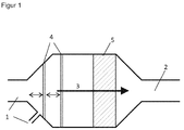
- FIG. 1 shows a reactor R with a substantially cylindrical body, which tapers conically at both ends thereof.
- two supply lines reference numeral 1
- a discharge line 2 is provided at the other end of the reactor.
- baffles 5 are provided, the heat or dissipate and / or increase the surface, as well as a largely planar component 4 extends over the entire cross section of the reactor R and is arranged substantially perpendicular to the main flow direction 3 of the reactor R.
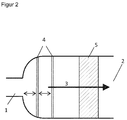
- FIG. 2 shows a largely analogous reactor R, but the one end of the reactor deviating from this is not conical, but dome-shaped. The other end of the reactor contains an outlet without changing the diameter.
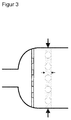
- FIG. 3 shown further preferred embodiment also shows a reactor R with dome-shaped ends, but here the internals 4 are formed as a perforated plate, and the largely planar member 5 as a series of tubes which are arranged perpendicular to the main flow direction 3 through the reactor R.
- FIG. 4 shows the use in an exhaust system of a marine diesel engine.
- the untreated exhaust gas stream 6 is fed to a combustion chamber 8 and additionally brought there by combustion of fuel by means of a burner 7 to the necessary temperature.
- the gas stream leaving the combustion chamber corresponds to reference number 1.
- the pressure loss measurement with differential pressure measurement is carried out before the first component and after the last component.
- the measurement of the maldistribution is carried out with a standard Prandtl pitot tube.
- the pitot tube is inserted as a towable probe.
- the maldistribution is measured behind the last component at a distance of 15 hydraulic diameters to the last component.
- 10 openings are drilled at the same distance over the reactor cross-section. 9 of them are each closed and the probe is guided through one.
- measurements of the velocity are made with the pitot tube.
- the maldistribution is determined as the standard deviation of the speed over these 100 measurement points.
- a reactor R is used according to the schematic representation in FIG. 1 but with a single supply line 1, with a diameter of 100 mm, which expands spontaneously to a rectangular cross section with the dimensions 170 x 330 mm.
- a first perforated plate with a hole diameter of 3 mm and a mean aperture ratio of 18% As largely flat components 3 perforated plates are used, a first perforated plate with a hole diameter of 3 mm and a mean aperture ratio of 18%, a second perforated plate with a hole diameter of also 3 mm and a mean aperture ratio of 18%, and a third perforated plate with a Hole diameter also 3 mm, but a mean aperture ratio of 17%.
- the thickness of the perforated plates is in each case 3 mm, and the perforated plates are arranged one behind the other at a distance of 95 mm. The distance from the inlet to the first perforated plate is 100 mm.
- the pressure loss is 8 mbar. A maldistribution of ⁇ 1% is determined.
- a reactor R is used analogously to the reactor R used in Example 1, with a single feed line 1, with a diameter of 100 mm, but with a conical widening of the same to 170 x 330 mm.
- a first perforated plate in the conical transition with the dimensions 120 x 240 mm, with a hole diameter of 3 mm, one of triangular pitch 6.0 mm and with a mean aperture ratio of about 22.5 %.
- a second perforated plate is also arranged in the conical transition, with the dimensions 150 x 300 mm, a hole diameter of 3 mm, a triangular pitch of 6.6 mm and a mean aperture ratio of about 18.7%.
- a third perforated plate is arranged in the rectangular, cuboid main part of the reactor R, with dimensions of 170 ⁇ 330 mm, a hole diameter of 3 mm, a triangular pitch of 7.2 mm and an average aperture ratio of about 15.8%.
- the perforated plates each have a thickness of 3 mm, and are arranged at a distance of 95 mm.
- the distance from the inlet to the first perforated plate is 100 mm.
- the pressure drop across the reactor R is 12 mbar. A maldistribution of ⁇ 1% is measured.
- a reactor R is used with a perforated plate and a supply line 1 with a diameter of 100 mm, which expands spontaneously to 170 x 330 mm.
- the perforated plate has a thickness of 3 mm, a hole diameter of 3 mm and an average aperture ratio of 2.6%.
- the distance from the inlet to the perforated plate is 100 mm.
- the pressure drop across the reactor R is 130 mbar.
- a maldistribution of 1% is measured.
- the pressure drop across the reactor R is 13 mbar. A miscalculation of 10% is measured.
- a reactor R is used with a single feed line 1, with a diameter of 500 mm and a dished bottom widening to a diameter of 2,500 mm.
- a uniform distribution device also a single perforated plate, with a plate thickness of 5 mm, a hole diameter of 5 mm, a triangular pitch of 41 mm, and a mean aperture ratio of 1.3% is used.
- the distance from the inlet to the perforated plate is 250 mm.
- a fluid flow of 20 t / h, a density of 1.05 kg / m 3 and a viscosity of 0.0243 mPas is passed through.
- the pressure drop across the reactor R is 62 mbar.
- a reactor R is used with two nets, a transverse flowed row of tubes and a perforated plate, as largely planar components. 4
- the supply line 1 is a pipe with a diameter of 500 mm, with a dished bottom widening to a diameter of 2,500 mm.
- the first network has an average aperture ratio of 60%
- the second network an average aperture ratio of 50%
- the Querangeströmte tube row has an average aperture ratio of 40%.
- the perforated plate has a plate thickness of 5 mm and an average aperture ratio of 8%.
- the distance from the inlet to the perforated plate is 250 mm.
- the pressure drop across the reactor R is less than 8 mbar. A maldistribution of 3% is measured.
- a reactor R is used with a tube bundle in the main flow direction, a transversely flowed row of tubes and a perforated plate.
- the supply line is designed analogously to Embodiment 3.
- a querangeströmte row of tubes with an average aperture ratio of 41%, a tube diameter of 30 mm and a tube spacing of 40 mm from tube center to tube center.
- the perforated plate with a plate thickness of 5 mm has an average aperture ratio of 7.5% and a distance from the inlet to the perforated plate of 250 mm.
- the pressure drop across the reactor R is about 2 mbar. A maldistribution of 3% is measured.
- a reactor R is used according to the schematic representation in FIG. 1 but with a single feed line 1, with a diameter of 1,000 mm, which spontaneously expands to a rectangular cross section measuring 1,700 x 3,300 mm.
- a first perforated plate with a hole diameter of 5 mm and a mean aperture ratio of 18% As largely flat components 3 perforated plates are used, a first perforated plate with a hole diameter of 5 mm and a mean aperture ratio of 18%, a second perforated plate with a hole diameter of also 5 mm and a mean aperture ratio of 18%, and a third perforated plate with a Hole diameter also 5 mm and a mean opening ratio of also 18%.
- the thickness of the perforated plates is 5 mm in each case, and the perforated plates are arranged one behind the other at a distance of 250 mm.
- the distance from the inlet to the first perforated plate is 500 mm.
- the pressure loss is about 9 mbar. A maldistribution of ⁇ 1% is determined.
- a reactor R is used according to the schematic representation in FIG. 1 but with a single feed line 1, with a diameter of 1,000 mm, the spontaneously expanding to a rectangular cross-section measuring 1,700 x 3,300 mm.
- a first perforated plate with a hole diameter of 5 mm and a mean aperture ratio of 35% As largely flat components 3 perforated plates are used, a first perforated plate with a hole diameter of 5 mm and a mean aperture ratio of 35%, a second perforated plate with a hole diameter of also 5 mm and a mean aperture ratio of 30%, and a third perforated plate with a Hole diameter also 5 mm, but a mean aperture ratio of 18%.
- the thickness of the perforated plates is 5 mm in each case, and the perforated plates are arranged one behind the other at a distance of 250 mm.
- the distance from the inlet to the first perforated plate is 500 mm.
- the pressure loss is about 5 mbar. It is determined a maldistribution of about 1%.
Landscapes
- Chemical & Material Sciences (AREA)
- Organic Chemistry (AREA)
- Chemical Kinetics & Catalysis (AREA)
- Physics & Mathematics (AREA)
- Thermal Sciences (AREA)
- Physical Or Chemical Processes And Apparatus (AREA)
Claims (12)
- Soit un réacteur (R) pourvu à une extrémité d'une ou plusieurs lignes d'alimentation (1) pour un ou plusieurs flux de fluide, chacun ayant une température de 200 °C ou plus, et pourvu à une autre extrémité du réacteur (R) d'un ou plusieurs conduits d'évacuation (2) pour le mélange de réaction , moyennant quoi une direction principale d'écoulement (3) à travers le réacteur (R) est définie, la surface en coupe transversale totale des canalisations d'alimentation ΣAi étant inférieure à l'aire AR de la coupe transversale du réacteur (R), réacteur également pourvu d'éléments de montage en son sein permettant l'apport ou l'évacuation de chaleur et/ou encore l'accroissement de la surface d'échange sur laquelle une réaction a lieu, le réacteur (R) étant également pourvu d'un dispositif permettant une distribution uniforme placé devant lesdits éléments dans le sens principal de l'écoulement, ce réacteur étant caractérisé en ce que :- Le dispositif de distribution uniforme est constitué de trois ou plus de pièces (4) de géométrie sensiblement plane , ce à quoi on entend par pièces de géométrie sensiblement plane des pièces présentant un allongement dans le sens principal de l'écoulement le long du réacteur d'au moins un facteur 2, de préférence d'un facteur 5 au moins ou mieux encore d'au moins un facteur 10 plus petit que l'allongement desdites pièces dans le sens perpendiculaire à la direction principale de l'écoulement le long du réacteur (R), - chacune des pièces s'étendant sur toute la section transversale du réacteur (R) et- les pièces qui sont agencées dans une large mesure perpendiculairement à la direction principale d'écoulement (3) le long du réacteur (R),- le réacteur (R) étant également caractérisé par des ouvertures pour le passage de l'un ou plusieurs fluides , de telle sorte que le diamètre hydraulique dh de chacun des trois (ou plus) éléments (4) sensiblement plans, défini par dh = 4 V / S, où V est le volume d'écoulement du fluide de l'élément sensiblement plan considéré (4) et où O représente la surface mouillée par le fluide de l'élément sensiblement plan, ce diamètre hydraulique s'étalant sur une plage de 0,5 mm à 1/10 du diamètre hydraulique Dh du réacteur (R), moyennant quoi- chacun des éléments (4) de géométrie sensiblement plane juxtaposés l'un sur l'autre étant espacés l'un respectivement à l'autre, dans le sens d'écoulement principal (3) le long du réacteur (R) de moins de la moitié du diamètre hydraulique Dh du réacteur (R) et de plus que la plus grande valeur résultant de 10 fois le diamètre hydraulique de chacun des éléments sensiblement plans (4) positionnés immédiatement en amont, et espacésd'1/4 de diamètre hydraulique de la conduite d'alimentation (1) de plus grande section transversale Ai.
- Soit un réacteur (R) selon la revendication 1, caractérisé en ce que le diamètre hydraulique dh de chacun des trois (ou plus) éléments (4) de géométrie sensiblement plane s'établit dans un domaine allant de 1 mm jusqu'à la plus petite des valeurs choisies entre le plus petit des diamètres hydrauliques d'une ou de plusieurs conduites d'alimentation (1) et 1/10 du diamètre hydraulique Dh du réacteur (R).
- Soit un réacteur (R) selon l'une des revendications 1 ou 2, caractérisé en ce que l'inverse du rapport d'ouverture ε moyen, pour chacun des trois (ou plus) des éléments sensiblement plans (4), en fonction du rapport de l'aire totale en section transversale pour les lignes d'alimentation (1) ΣAi à la section transversale maximale AR du réacteur (R) se trouve dans une plage de valeurs défini par l'équation suivante

- Soit un réacteur (R) d'après l'une des revendications 1 à 3 , caractérisé en ce que trois éléments (4) de géométrie sensiblement plane sont prévus, et en ce que la valeur inverse du rapport d'ouverture ε moyen pour chacun des trois éléments (4) de géométrie sensiblement plane se trouve dans un domaine de valeurs défini par l'équation suivante, fonction du rapport de l'aire totale en section transversale pour les lignes d'alimentation (1) ΣAi à la surface maximale de coupe transversale AR du réacteur (R),

- Soit un réacteur (R) selon l'une des revendications 1 à 3, caractérisé en ce que quatre, voire plus, éléments (4) de géométrie sensiblement plane sont prévus, et en ce que la valeur inverse de la moyenne de rapport d'ouverture ε pour chacun desdits éléments (4) de géométrie sensiblement plane, cette valeur inverse étant elle-même fonction du rapport de l'aire totale en section transversale pour les lignes d'alimentation (1) Σ4i à l'aire maximale de section transversale AR du réacteur (R), est comprise dans une plage de valeurs définie par l'équation suivante,

- Soit un réacteur (R) selon l'une des revendications 1 à 5, caractérisé en ce que le dernier des éléments (4) de géométrie sensiblement plane au nombre minimum de trois ou plus, pris dans la direction principale d'écoulement (3) le long du réacteur (R), présente un rapport d'ouverture moyen ε, qui est au plus aussi grand ou est plus petit que le rapport d'ouverture moyen de chacun des éléments (4) de géométrie sensiblement plane placés en amont et pris dans la direction principale d'écoulement (3) le long du réacteur (R).
- Soit un réacteur (R) selon l'une des revendications 1 à 6, caractérisé en ce que le premier des éléments (4) de géométrie sensiblement plane au nombre minimum de trois voire plus, pris dans la direction principale d'écoulement (3) le long du réacteur (R), présente un rapport d'ouverture moyen ε, qui est au moins aussi grand voire plus grand que le rapport d'ouverture moyen de chacun des éléments (4) placés en aval et pris dans la direction principale d'écoulement (3) le long du réacteur (R).
- Soit un réacteur (R) selon l'une des revendications de 1 à 7 , caractérisé en ce que le rapport du rapport d'ouverture ε1 du premier élément (4) de géométrie sensiblement plane au rapport d'ouverture moyen εn du dernier élément (4) de géométrie sensiblement plane est compris dans une plage de valeurs déterminées par l'équation suivante

- Soit un réacteur (R) selon l'une des revendications 1 à 8, caractérisé par une aire maximale de section transversale AR comprise entre 0,1 à 10,0 m2, de préférence comprise entre 1 à 2m2.
- Utilisation du réacteur (R) selon l'une des revendications 1 à 9 pour réaliser des réactions à des températures de réaction dans une plage de 200 ° C à 1000 ° C, de préférence à des températures de réaction dans une plage de 300 ° C à 1000 ° C, de préférence à des températures de réaction dans une plage allant de 500 ° C à 1000 ° C
- Utilisation selon la revendication 10, caractérisée en ce que les réactions concernées sont des réactions de déshydrogénation , de préférence de déshydrogénation du propane ou du butane, de réaction de production d'acide nitrique ou de réaction de production de formaldehyde.
- Utilisation selon la revendication 10, caractérisée en ce que le réacteur (R) est un système de purification de gaz d'échappement pour un moteur diesel de bateaux.
Applications Claiming Priority (1)
| Application Number | Priority Date | Filing Date | Title |
|---|---|---|---|
| DE102012017069 | 2012-08-29 |
Publications (2)
| Publication Number | Publication Date |
|---|---|
| EP2703076A1 EP2703076A1 (fr) | 2014-03-05 |
| EP2703076B1 true EP2703076B1 (fr) | 2016-04-27 |
Family
ID=49035473
Family Applications (1)
| Application Number | Title | Priority Date | Filing Date |
|---|---|---|---|
| EP13182077.1A Active EP2703076B1 (fr) | 2012-08-29 | 2013-08-28 | Réacteur pourvu d'une ou plusieurs conduites d'entrée de fluide et d'un dispositif de distribution desdits fluides |
Country Status (1)
| Country | Link |
|---|---|
| EP (1) | EP2703076B1 (fr) |
Family Cites Families (8)
| Publication number | Priority date | Publication date | Assignee | Title |
|---|---|---|---|---|
| DE2439144C3 (de) * | 1974-08-14 | 1979-04-05 | Siemens Ag, 1000 Berlin Und 8000 Muenchen | Vorrichtung zum Verteilen strömender Medien von einem Strömungsquerschnitt auf einen davon verschiedenen Strömungsquerschnitt |
| SG45121A1 (en) * | 1995-10-28 | 1998-01-16 | Inst Of Microelectronics | Apparatus for dispensing fluid in an array pattern |
| US20080159069A1 (en) * | 2005-04-06 | 2008-07-03 | Stichting Voor De Technische Wentenschappen | Inlet Section for Micro-Reactor |
| DE102006060507A1 (de) * | 2006-12-19 | 2008-06-26 | Basf Se | Reaktor zur Durchführung einer Reaktion zwischen zwei fluiden Edukten an einem Katalysatorbett mit Vorvermischen der fluiden Edukte in einer Einmischvorrichtung |
| DE102007034715A1 (de) * | 2007-07-23 | 2009-01-29 | Evonik Röhm Gmbh | Reaktor zur Herstellung von Cyanwasserstoff nach dem Andrussow-Verfahren |
| TW200936245A (en) * | 2007-10-30 | 2009-09-01 | Basf Se | Horizontal reactor for reacting a fluid feed stream with a fluid oxidant stream in the presence of a solid catalyst |
| EP2389241B1 (fr) * | 2009-01-21 | 2018-06-06 | Basf Se | Réacteur à faisceau tubulaire et procédé pour des réactions non catalysées ou de catalyse homogène |
| JP5447895B2 (ja) * | 2009-12-01 | 2014-03-19 | ビーエーエスエフ ソシエタス・ヨーロピア | 自熱式の気相脱水素を実施するための反応器 |
-
2013
- 2013-08-28 EP EP13182077.1A patent/EP2703076B1/fr active Active
Also Published As
| Publication number | Publication date |
|---|---|
| EP2703076A1 (fr) | 2014-03-05 |
Similar Documents
| Publication | Publication Date | Title |
|---|---|---|
| DE2439144C3 (de) | Vorrichtung zum Verteilen strömender Medien von einem Strömungsquerschnitt auf einen davon verschiedenen Strömungsquerschnitt | |
| EP1940541B1 (fr) | Dispositif repartiteur de melange de phase gazeuse et liquide pour des appareils | |
| EP2517784B1 (fr) | Pre-mixing device between two fluids for a reactor with a catalytic bed | |
| EP2550088B1 (fr) | Procede et dispositif destines a la dispersion | |
| EP2680957B1 (fr) | Procédé et dispositif de mélange de deux courants de fluide | |
| DE19929765A1 (de) | Reinigungseinrichtung für Rauchgas | |
| DE112011104474T5 (de) | Säulen-Kontaktanlage und Verfahren für ihren Betrieb | |
| DE102011014750A1 (de) | Vorrichtung zur Umsetzung und Separation von Phasen | |
| EP2703076B1 (fr) | Réacteur pourvu d'une ou plusieurs conduites d'entrée de fluide et d'un dispositif de distribution desdits fluides | |
| DE102012100344A1 (de) | Mikroreaktor für katalytische Reaktionen | |
| DE112017005323T5 (de) | Substratform, Geometrie, Positionierung und/oder Zelldichte zur Verbesserung der Nachbehandlungsleistung | |
| EP2163300B1 (fr) | Utilisation d'une plaque de distribution d'écoulements fluidiques | |
| EP0751820B1 (fr) | Systeme combine d'amenee et de melange | |
| DE3042090A1 (de) | Reaktor fuer katalytische reaktionen | |
| DE112018007799T5 (de) | Zersetzungsreaktor mit körpermischung | |
| EP3368473B1 (fr) | Dispositif et procédé pour produire un gaz de synthèse | |
| DE102022102097A1 (de) | Additiv hergestellte katalysatorsubstrate | |
| EP1317955A2 (fr) | Dispositif et procédé pour des réactions heterogeniques catalytiques | |
| DE102008003044B4 (de) | Abgasreinigungssystem zur verbesserten Abgasreinigung durch konvektives Mischen | |
| DE102006006379B4 (de) | Verwendung einer Vorrichtung zur gleichmäßigen Verteilung von Stoffen | |
| DE10148926A1 (de) | Verteilerstruktur für Betriebsmittel, Verfahren zu ihrer Herstellung und ihre Verwendung | |
| EP3153465A1 (fr) | Reformateur destine a la fabrication d'un gaz de synthese | |
| DE102013022009A1 (de) | Vorrichtung zur Nachbehandlung von Abgasen eines Verbrennungsmotors | |
| EP3610141A1 (fr) | Système d'échappement | |
| DE202012011813U1 (de) | Abgasnachbehandlungssystem |
Legal Events
| Date | Code | Title | Description |
|---|---|---|---|
| AK | Designated contracting states |
Kind code of ref document: A1 Designated state(s): AL AT BE BG CH CY CZ DE DK EE ES FI FR GB GR HR HU IE IS IT LI LT LU LV MC MK MT NL NO PL PT RO RS SE SI SK SM TR |
|
| AX | Request for extension of the european patent |
Extension state: BA ME |
|
| PUAI | Public reference made under article 153(3) epc to a published international application that has entered the european phase |
Free format text: ORIGINAL CODE: 0009012 |
|
| 17P | Request for examination filed |
Effective date: 20140905 |
|
| RBV | Designated contracting states (corrected) |
Designated state(s): AL AT BE BG CH CY CZ DE DK EE ES FI FR GB GR HR HU IE IS IT LI LT LU LV MC MK MT NL NO PL PT RO RS SE SI SK SM TR |
|
| RIC1 | Information provided on ipc code assigned before grant |
Ipc: B01J 19/32 20060101ALI20150824BHEP Ipc: B01J 8/02 20060101ALI20150824BHEP Ipc: B01J 19/00 20060101AFI20150824BHEP Ipc: B01J 19/24 20060101ALI20150824BHEP Ipc: B01J 19/30 20060101ALI20150824BHEP |
|
| GRAP | Despatch of communication of intention to grant a patent |
Free format text: ORIGINAL CODE: EPIDOSNIGR1 |
|
| INTG | Intention to grant announced |
Effective date: 20151113 |
|
| RAP1 | Party data changed (applicant data changed or rights of an application transferred) |
Owner name: GERLINGER, WOLFGANG Owner name: BASF SCHWEIZ AG Owner name: OLBERT, GERHARD |
|
| GRAS | Grant fee paid |
Free format text: ORIGINAL CODE: EPIDOSNIGR3 |
|
| GRAA | (expected) grant |
Free format text: ORIGINAL CODE: 0009210 |
|
| AK | Designated contracting states |
Kind code of ref document: B1 Designated state(s): AL AT BE BG CH CY CZ DE DK EE ES FI FR GB GR HR HU IE IS IT LI LT LU LV MC MK MT NL NO PL PT RO RS SE SI SK SM TR |
|
| REG | Reference to a national code |
Ref country code: GB Ref legal event code: FG4D Free format text: NOT ENGLISH |
|
| REG | Reference to a national code |
Ref country code: CH Ref legal event code: EP |
|
| REG | Reference to a national code |
Ref country code: AT Ref legal event code: REF Ref document number: 794107 Country of ref document: AT Kind code of ref document: T Effective date: 20160515 |
|
| REG | Reference to a national code |
Ref country code: IE Ref legal event code: FG4D Free format text: LANGUAGE OF EP DOCUMENT: GERMAN |
|
| REG | Reference to a national code |
Ref country code: DE Ref legal event code: R096 Ref document number: 502013002750 Country of ref document: DE |
|
| REG | Reference to a national code |
Ref country code: LT Ref legal event code: MG4D |
|
| REG | Reference to a national code |
Ref country code: NL Ref legal event code: MP Effective date: 20160427 |
|
| PG25 | Lapsed in a contracting state [announced via postgrant information from national office to epo] |
Ref country code: NL Free format text: LAPSE BECAUSE OF FAILURE TO SUBMIT A TRANSLATION OF THE DESCRIPTION OR TO PAY THE FEE WITHIN THE PRESCRIBED TIME-LIMIT Effective date: 20160427 |
|
| PG25 | Lapsed in a contracting state [announced via postgrant information from national office to epo] |
Ref country code: PL Free format text: LAPSE BECAUSE OF FAILURE TO SUBMIT A TRANSLATION OF THE DESCRIPTION OR TO PAY THE FEE WITHIN THE PRESCRIBED TIME-LIMIT Effective date: 20160427 Ref country code: LT Free format text: LAPSE BECAUSE OF FAILURE TO SUBMIT A TRANSLATION OF THE DESCRIPTION OR TO PAY THE FEE WITHIN THE PRESCRIBED TIME-LIMIT Effective date: 20160427 Ref country code: NO Free format text: LAPSE BECAUSE OF FAILURE TO SUBMIT A TRANSLATION OF THE DESCRIPTION OR TO PAY THE FEE WITHIN THE PRESCRIBED TIME-LIMIT Effective date: 20160727 Ref country code: FI Free format text: LAPSE BECAUSE OF FAILURE TO SUBMIT A TRANSLATION OF THE DESCRIPTION OR TO PAY THE FEE WITHIN THE PRESCRIBED TIME-LIMIT Effective date: 20160427 |
|
| PG25 | Lapsed in a contracting state [announced via postgrant information from national office to epo] |
Ref country code: LV Free format text: LAPSE BECAUSE OF FAILURE TO SUBMIT A TRANSLATION OF THE DESCRIPTION OR TO PAY THE FEE WITHIN THE PRESCRIBED TIME-LIMIT Effective date: 20160427 Ref country code: RS Free format text: LAPSE BECAUSE OF FAILURE TO SUBMIT A TRANSLATION OF THE DESCRIPTION OR TO PAY THE FEE WITHIN THE PRESCRIBED TIME-LIMIT Effective date: 20160427 Ref country code: SE Free format text: LAPSE BECAUSE OF FAILURE TO SUBMIT A TRANSLATION OF THE DESCRIPTION OR TO PAY THE FEE WITHIN THE PRESCRIBED TIME-LIMIT Effective date: 20160427 Ref country code: PT Free format text: LAPSE BECAUSE OF FAILURE TO SUBMIT A TRANSLATION OF THE DESCRIPTION OR TO PAY THE FEE WITHIN THE PRESCRIBED TIME-LIMIT Effective date: 20160829 Ref country code: HR Free format text: LAPSE BECAUSE OF FAILURE TO SUBMIT A TRANSLATION OF THE DESCRIPTION OR TO PAY THE FEE WITHIN THE PRESCRIBED TIME-LIMIT Effective date: 20160427 Ref country code: GR Free format text: LAPSE BECAUSE OF FAILURE TO SUBMIT A TRANSLATION OF THE DESCRIPTION OR TO PAY THE FEE WITHIN THE PRESCRIBED TIME-LIMIT Effective date: 20160728 Ref country code: ES Free format text: LAPSE BECAUSE OF FAILURE TO SUBMIT A TRANSLATION OF THE DESCRIPTION OR TO PAY THE FEE WITHIN THE PRESCRIBED TIME-LIMIT Effective date: 20160427 |
|
| PG25 | Lapsed in a contracting state [announced via postgrant information from national office to epo] |
Ref country code: IT Free format text: LAPSE BECAUSE OF FAILURE TO SUBMIT A TRANSLATION OF THE DESCRIPTION OR TO PAY THE FEE WITHIN THE PRESCRIBED TIME-LIMIT Effective date: 20160427 Ref country code: BE Free format text: LAPSE BECAUSE OF NON-PAYMENT OF DUE FEES Effective date: 20160831 |
|
| REG | Reference to a national code |
Ref country code: DE Ref legal event code: R097 Ref document number: 502013002750 Country of ref document: DE |
|
| PG25 | Lapsed in a contracting state [announced via postgrant information from national office to epo] |
Ref country code: SK Free format text: LAPSE BECAUSE OF FAILURE TO SUBMIT A TRANSLATION OF THE DESCRIPTION OR TO PAY THE FEE WITHIN THE PRESCRIBED TIME-LIMIT Effective date: 20160427 Ref country code: CZ Free format text: LAPSE BECAUSE OF FAILURE TO SUBMIT A TRANSLATION OF THE DESCRIPTION OR TO PAY THE FEE WITHIN THE PRESCRIBED TIME-LIMIT Effective date: 20160427 Ref country code: EE Free format text: LAPSE BECAUSE OF FAILURE TO SUBMIT A TRANSLATION OF THE DESCRIPTION OR TO PAY THE FEE WITHIN THE PRESCRIBED TIME-LIMIT Effective date: 20160427 Ref country code: RO Free format text: LAPSE BECAUSE OF FAILURE TO SUBMIT A TRANSLATION OF THE DESCRIPTION OR TO PAY THE FEE WITHIN THE PRESCRIBED TIME-LIMIT Effective date: 20160427 Ref country code: DK Free format text: LAPSE BECAUSE OF FAILURE TO SUBMIT A TRANSLATION OF THE DESCRIPTION OR TO PAY THE FEE WITHIN THE PRESCRIBED TIME-LIMIT Effective date: 20160427 |
|
| PG25 | Lapsed in a contracting state [announced via postgrant information from national office to epo] |
Ref country code: SM Free format text: LAPSE BECAUSE OF FAILURE TO SUBMIT A TRANSLATION OF THE DESCRIPTION OR TO PAY THE FEE WITHIN THE PRESCRIBED TIME-LIMIT Effective date: 20160427 |
|
| PLBE | No opposition filed within time limit |
Free format text: ORIGINAL CODE: 0009261 |
|
| STAA | Information on the status of an ep patent application or granted ep patent |
Free format text: STATUS: NO OPPOSITION FILED WITHIN TIME LIMIT |
|
| PG25 | Lapsed in a contracting state [announced via postgrant information from national office to epo] |
Ref country code: MC Free format text: LAPSE BECAUSE OF FAILURE TO SUBMIT A TRANSLATION OF THE DESCRIPTION OR TO PAY THE FEE WITHIN THE PRESCRIBED TIME-LIMIT Effective date: 20160427 |
|
| REG | Reference to a national code |
Ref country code: CH Ref legal event code: PL |
|
| 26N | No opposition filed |
Effective date: 20170130 |
|
| PG25 | Lapsed in a contracting state [announced via postgrant information from national office to epo] |
Ref country code: LI Free format text: LAPSE BECAUSE OF NON-PAYMENT OF DUE FEES Effective date: 20160831 Ref country code: CH Free format text: LAPSE BECAUSE OF NON-PAYMENT OF DUE FEES Effective date: 20160831 |
|
| REG | Reference to a national code |
Ref country code: FR Ref legal event code: ST Effective date: 20170428 |
|
| PG25 | Lapsed in a contracting state [announced via postgrant information from national office to epo] |
Ref country code: SI Free format text: LAPSE BECAUSE OF FAILURE TO SUBMIT A TRANSLATION OF THE DESCRIPTION OR TO PAY THE FEE WITHIN THE PRESCRIBED TIME-LIMIT Effective date: 20160427 |
|
| REG | Reference to a national code |
Ref country code: IE Ref legal event code: MM4A |
|
| PG25 | Lapsed in a contracting state [announced via postgrant information from national office to epo] |
Ref country code: IE Free format text: LAPSE BECAUSE OF NON-PAYMENT OF DUE FEES Effective date: 20160828 Ref country code: FR Free format text: LAPSE BECAUSE OF NON-PAYMENT OF DUE FEES Effective date: 20160831 |
|
| PG25 | Lapsed in a contracting state [announced via postgrant information from national office to epo] |
Ref country code: LU Free format text: LAPSE BECAUSE OF NON-PAYMENT OF DUE FEES Effective date: 20160828 |
|
| GBPC | Gb: european patent ceased through non-payment of renewal fee |
Effective date: 20170828 |
|
| PG25 | Lapsed in a contracting state [announced via postgrant information from national office to epo] |
Ref country code: HU Free format text: LAPSE BECAUSE OF FAILURE TO SUBMIT A TRANSLATION OF THE DESCRIPTION OR TO PAY THE FEE WITHIN THE PRESCRIBED TIME-LIMIT; INVALID AB INITIO Effective date: 20130828 Ref country code: CY Free format text: LAPSE BECAUSE OF FAILURE TO SUBMIT A TRANSLATION OF THE DESCRIPTION OR TO PAY THE FEE WITHIN THE PRESCRIBED TIME-LIMIT Effective date: 20160427 |
|
| PG25 | Lapsed in a contracting state [announced via postgrant information from national office to epo] |
Ref country code: MT Free format text: LAPSE BECAUSE OF FAILURE TO SUBMIT A TRANSLATION OF THE DESCRIPTION OR TO PAY THE FEE WITHIN THE PRESCRIBED TIME-LIMIT Effective date: 20160427 Ref country code: MK Free format text: LAPSE BECAUSE OF FAILURE TO SUBMIT A TRANSLATION OF THE DESCRIPTION OR TO PAY THE FEE WITHIN THE PRESCRIBED TIME-LIMIT Effective date: 20160427 Ref country code: IS Free format text: LAPSE BECAUSE OF FAILURE TO SUBMIT A TRANSLATION OF THE DESCRIPTION OR TO PAY THE FEE WITHIN THE PRESCRIBED TIME-LIMIT Effective date: 20160427 Ref country code: TR Free format text: LAPSE BECAUSE OF FAILURE TO SUBMIT A TRANSLATION OF THE DESCRIPTION OR TO PAY THE FEE WITHIN THE PRESCRIBED TIME-LIMIT Effective date: 20160427 |
|
| PG25 | Lapsed in a contracting state [announced via postgrant information from national office to epo] |
Ref country code: BG Free format text: LAPSE BECAUSE OF FAILURE TO SUBMIT A TRANSLATION OF THE DESCRIPTION OR TO PAY THE FEE WITHIN THE PRESCRIBED TIME-LIMIT Effective date: 20160427 Ref country code: GB Free format text: LAPSE BECAUSE OF NON-PAYMENT OF DUE FEES Effective date: 20170828 |
|
| PG25 | Lapsed in a contracting state [announced via postgrant information from national office to epo] |
Ref country code: AL Free format text: LAPSE BECAUSE OF FAILURE TO SUBMIT A TRANSLATION OF THE DESCRIPTION OR TO PAY THE FEE WITHIN THE PRESCRIBED TIME-LIMIT Effective date: 20160427 |
|
| REG | Reference to a national code |
Ref country code: AT Ref legal event code: MM01 Ref document number: 794107 Country of ref document: AT Kind code of ref document: T Effective date: 20180828 |
|
| PG25 | Lapsed in a contracting state [announced via postgrant information from national office to epo] |
Ref country code: AT Free format text: LAPSE BECAUSE OF NON-PAYMENT OF DUE FEES Effective date: 20180828 |
|
| PGFP | Annual fee paid to national office [announced via postgrant information from national office to epo] |
Ref country code: DE Payment date: 20230831 Year of fee payment: 11 |