EP2516723B1 - Centrale vapeur équipée d'un générateur de vapeur - Google Patents
Centrale vapeur équipée d'un générateur de vapeur Download PDFInfo
- Publication number
- EP2516723B1 EP2516723B1 EP10798809.9A EP10798809A EP2516723B1 EP 2516723 B1 EP2516723 B1 EP 2516723B1 EP 10798809 A EP10798809 A EP 10798809A EP 2516723 B1 EP2516723 B1 EP 2516723B1
- Authority
- EP
- European Patent Office
- Prior art keywords
- steam
- sequence
- station
- discharges
- actuating element
- Prior art date
- Legal status (The legal status is an assumption and is not a legal conclusion. Google has not performed a legal analysis and makes no representation as to the accuracy of the status listed.)
- Active
Links
- XEEYBQQBJWHFJM-UHFFFAOYSA-N Iron Chemical compound [Fe] XEEYBQQBJWHFJM-UHFFFAOYSA-N 0.000 claims description 64
- 229910052742 iron Inorganic materials 0.000 claims description 32
- 238000000034 method Methods 0.000 claims description 18
- 230000008569 process Effects 0.000 claims description 15
- 230000008020 evaporation Effects 0.000 claims 2
- 238000001704 evaporation Methods 0.000 claims 2
- 238000010409 ironing Methods 0.000 description 40
- 238000004140 cleaning Methods 0.000 description 11
- 238000010438 heat treatment Methods 0.000 description 7
- 239000000463 material Substances 0.000 description 7
- XLYOFNOQVPJJNP-UHFFFAOYSA-N water Substances O XLYOFNOQVPJJNP-UHFFFAOYSA-N 0.000 description 7
- 230000008859 change Effects 0.000 description 5
- 238000005265 energy consumption Methods 0.000 description 5
- 238000003825 pressing Methods 0.000 description 5
- 230000009467 reduction Effects 0.000 description 5
- 239000012141 concentrate Substances 0.000 description 4
- 230000008901 benefit Effects 0.000 description 3
- 238000006073 displacement reaction Methods 0.000 description 3
- 239000007788 liquid Substances 0.000 description 3
- 238000011161 development Methods 0.000 description 2
- 230000018109 developmental process Effects 0.000 description 2
- 238000010586 diagram Methods 0.000 description 2
- 238000005485 electric heating Methods 0.000 description 2
- 230000006872 improvement Effects 0.000 description 2
- 230000003993 interaction Effects 0.000 description 2
- 230000035515 penetration Effects 0.000 description 2
- 238000009834 vaporization Methods 0.000 description 2
- 230000008016 vaporization Effects 0.000 description 2
- 230000005540 biological transmission Effects 0.000 description 1
- 238000012790 confirmation Methods 0.000 description 1
- 230000001419 dependent effect Effects 0.000 description 1
- 238000001035 drying Methods 0.000 description 1
- 230000000694 effects Effects 0.000 description 1
- 230000005611 electricity Effects 0.000 description 1
- 230000000670 limiting effect Effects 0.000 description 1
- 238000007726 management method Methods 0.000 description 1
- 230000001172 regenerating effect Effects 0.000 description 1
- 238000010025 steaming Methods 0.000 description 1
- 230000002123 temporal effect Effects 0.000 description 1
- 239000004753 textile Substances 0.000 description 1
Images

Classifications
-
- D—TEXTILES; PAPER
- D06—TREATMENT OF TEXTILES OR THE LIKE; LAUNDERING; FLEXIBLE MATERIALS NOT OTHERWISE PROVIDED FOR
- D06F—LAUNDERING, DRYING, IRONING, PRESSING OR FOLDING TEXTILE ARTICLES
- D06F75/00—Hand irons
- D06F75/08—Hand irons internally heated by electricity
- D06F75/10—Hand irons internally heated by electricity with means for supplying steam to the article being ironed
- D06F75/12—Hand irons internally heated by electricity with means for supplying steam to the article being ironed the steam being produced from water supplied to the iron from an external source
-
- F—MECHANICAL ENGINEERING; LIGHTING; HEATING; WEAPONS; BLASTING
- F22—STEAM GENERATION
- F22B—METHODS OF STEAM GENERATION; STEAM BOILERS
- F22B1/00—Methods of steam generation characterised by form of heating method
- F22B1/28—Methods of steam generation characterised by form of heating method in boilers heated electrically
- F22B1/284—Methods of steam generation characterised by form of heating method in boilers heated electrically with water in reservoirs
- F22B1/285—Methods of steam generation characterised by form of heating method in boilers heated electrically with water in reservoirs the water being fed by a pump to the reservoirs
Definitions
- the present invention relates to a steam station for steaming a Bedampfungsguts with a steam generator for generating a steam ejection, and an actuating element.
- a steam ironing station with a steam station and a steam iron
- the steam station having a steam generator.
- the steam generated in the steam generator is passed through a steam line in the steam iron.
- the steam is routed through steam guides in the iron soleplate heated by a heater.
- a feed pump is provided, which promotes water from a water tank directly into the steam line, whereby it is achieved that the exiting at the soleplate steam has a high humidity.
- the invention has for its object to provide a comparison with the prior art improved steam station.
- a steam station is to be provided in which a steam discharge with the highest possible pressure can be achieved.
- the steam discharge rate of a steam ejection should be increased.
- a steam station is to be provided, through which a reduction in energy consumption is possible.
- a time-unlimited sequence of steam surges is a consequence that advantageously runs after starting so long until the actuator again is operated to end the series of steam discharges.
- a time-limited sequence is understood to mean a sequence which ends after a predetermined time has elapsed, so that the steam generator no longer gives off a series of steam discharges after the predetermined time has elapsed. However, this does not mean that the steam generator does not give off any steam after passing through the time-limited sequence.
- the temporally limited sequence that is after the expiration of the predetermined time, still a constant output of steam can be delivered.
- the operation of the steam generator can be simplified by a time-limited sequence of steam discharges, since the user during use, eg during a ironing operation, the time-limited sequence can start by operating the actuator without having to end this by re-operating again since this ends advantageously after the expiration of the predetermined time.
- the user can concentrate better on the actual work process, such as an ironing or cleaning process.
- a steam station is to be understood as a system for providing and / or delivering steam in order to be able to treat a material to be steamed.
- the steam generator can generate at least one steam output.
- the steam station can be used, for example, for the care of clothing, and be designed for this purpose, for example, as ironing, ironing station, steam straightener, so-called steam brush or steam brush.
- a steam station according to the invention can also be used for cleaning purposes, and be designed, for example, as a steam cleaner.
- a series of steam ejections is a sequence in which phases alternate with higher steam ejection rates and phases with lower or no steam ejection rates. The phases with a higher steam discharge rate are considered as steam discharges from the series of steam discharges.
- a series of steam bursts may also be referred to as a result of steam pulses.
- a steam discharge rate is the amount of steam that is released in a given time unit. Usually, the steam discharge rate is measured in grams per minute (g / min).
- the sequence of the sequence ie the change of phases with higher and phases with lower or no steam discharge rate, as well as the duration of the phases, is not affected. That the sequence of steam discharges is startable and / or terminable, while the steam station for processing the Bedampfungsguts means that a user does not have to interrupt the handling in order to start and / or end the sequence.
- handling is here to be understood the activity of a user that the user carries out in order to process the material to be steamed. This can be, for example, the guiding of an iron or a cleaning device.
- the steam ejection rate of the steam ejections can be increased by the sequence of steam ejections.
- the duration of each steam ejection may advantageously be so short that a pressure drop during steam ejection can be minimized, and thus a higher amount of steam can be transported during steam ejection.
- the vapor pressure dropped off during a steam discharge between the steam discharges can be regenerated again, that is, increased to the initial pressure value.
- the initial pressure value is the value of the vapor pressure prevailing at the beginning of a steam discharge, ie before the beginning of a pressure drop. Usually, the initial pressure value is the highest vapor pressure of a vapor ejection.
- each steam ejection of a sequence has the same temporal vapor pressure profile, and thus an equally high steam ejection rate.
- an improvement of the working results can be achieved by the invention, since in the sequence of steam ejections, a higher steam discharge rate of the steam ejections can be achieved. As a result, the vapor may e.g. better penetrate the material to be ironed, or remove dirt from a surface better. Furthermore, due to the succession of steam discharges, an improved sliding of an iron on the ironing material can be achieved due to the constantly high vapor pressure of the steam ejections of the sequence.
- the user can select at any time during handling for processing the Bedampfungsguts, eg during ironing or cleaning process, whether he wants to operate the steam station with or without dispensing a series of steam discharges.
- an ironing or cleaning operation begins by engaging a portion of the steam station, e.g. an iron or a cleaning device, and ends with the release of the same.
- a portion of the steam station e.g. an iron or a cleaning device
- this energy can be saved, since the steam station can be operated without dispensing a series of steam discharges.
- the sequence of steam discharges can be started and / or terminated by the user via an operation of the actuating element, so that the user can start and / or terminate the sequence as required. Furthermore, it is advantageously achievable that the user does not have to control the sequence of the sequence, and thus is better able to concentrate on the working process, e.g. can concentrate a ironing or cleaning process.
- the duration of steam ejection of the series of steam ejections is so short that the pressure drop during steam ejection does not exceed 15%, more preferably 10%, most preferably 5%.
- the time period between successive steam ejections is at least 0.5 seconds, more preferably at least 1.0 seconds.
- each steam ejection has a maximum duration of 1.0 second, particularly preferably of 0.5 second maximum.
- the actuating element is operated by a tactile movement, wherein the actuating element can be brought by the tactile movement of a first switching state in a second switching state, and after completion of the tactile movement of the second in the first switching state.
- the actuating element has an elastic element, by means of which the actuating element can be brought from the second to the first switching state after the end of the scanning movement.
- the tactile movement may e.g. be a tap, press or pull and then release the actuator.
- the sequence of steam discharges can be started and / or terminated by the touch movement.
- the series of steam discharges e.g. started by a first touch movement, and terminated by a first following the second touch movement.
- no additional interaction of the user with the actuator is required to run the sequence of steam discharges. This may facilitate the ironing operation, since during the ironing operation, the user can start the series of steam discharges by a simple operation of the operating member, and concentrate on the actual ironing operation during the delivery of the steam discharges.
- the user can end the sequence of steam discharges at any time by re-operation of the actuating element.
- the actuator is brought by operation from a first switching state to a second switching state to start the series of steam discharges, and brought from the second to the first switching state to terminate the series of steam discharges.
- the actuator may be pushed or pulled to be brought from the first to the second state, and released to be brought from the second to the first state.
- the user while the user is in contact with the actuator during delivery of the train of vapor ejections, the user does not affect the course of the phases of the sequence through its interaction with the actuator.
- This may advantageously allow simplification of the operation for controlling the sequence of steam discharges, since the steam discharges are delivered only in the time in which the user interacts with the actuating element, for example by holding or pulling it.
- can an improvement of the ironing results are possible because the user with uneven wrinkling of the ironing the delivery of the steam ejections does not have to activate during the entire ironing process, but can selectively switch on and off.
- the actuating element is brought by a tactile movement in the first and / or second state, wherein the actuating element by a latching device in the respective position remains, and does not return to the previous state.
- a part of the actuating element is displaced during the operation of the actuating element in order to change the switching state of the actuating element between the first and second switching state.
- Such an actuator may e.g. be designed as a slide switch.
- the operation of the actuator is against a force, e.g. a spring force of an elastically deformable element, whereby accidental operation of the actuating element can be avoided.
- the sequence of steam discharges can be started and / or terminated by a first operating sequence of the actuating element.
- Under an operating sequence of the actuating element are caused by an operation to be understood, temporally successive, divergent states of the actuating element.
- the first operating sequence consists of a single touch movement. This means that the actuating element is operated by a tactile movement in order to start and / or end the series of steam ejections. This tactile movement can be compared with a "single click" when operating a computer mouse.
- the actuating element can be brought by operation in a third switching state to start the temporally limited sequence of steam ejections and / or to end.
- the time-limited sequence can also be terminated before the expiry of the predetermined time by operating the actuating element.
- the time-limited sequence has a fixed number of steam bursts.
- the predetermined time of the time-limited sequence is dimensioned in this embodiment so that after this time a fixed number of steam bursts was delivered.
- the user may also, if he has operated the actuator incorrectly, or no longer requires the steam ejections, terminate the time-limited sequence of steam ejections prematurely by re-operating the actuator.
- a time-limited sequence of steam discharges can be started and / or terminated by a second operating sequence of the actuating element.
- Under an operating sequence of the actuating element are caused by an operation to be understood, temporally successive, divergent states of the actuating element.
- the second operating sequence of two scanning movements of the actuating element wherein the time interval between the touch movements does not exceed a predetermined period of time.
- the actuating element is operated by a double touch movement in order to start and / or end the time-limited sequence of steam discharges.
- the time between the two tactile movements may not exceed a fixed period of time.
- This two-time tactile movement can be compared with a "double-click" when operating a computer mouse.
- the time interval between the individual scanning movements of the second operating sequence is particularly preferably a maximum of only one second, particularly preferably a maximum of only half a second.
- the two-time touch movement of the second sequence of operation a simple operation can be made possible because the user of such a sequence can already be known from the operation of a computer with a mouse.
- the steam station has a control unit for controlling the steam output.
- the actuating element is designed as a switch.
- the actuating element is designed as a push-button.
- the key switch may e.g. be pressed or pulled during an operation.
- the key switch can also be designed as a sensor switch, which is touched during operation. This touching can also be considered as a tactile movement.
- the key switch can be brought by operation in a first and second switching position.
- the first and / or second sequence of operations on an operating element designed as a push-button switch is easy to carry out, wherein the push-button switch can be operated by one-time or by two operations briefly in quick succession.
- such a key switch is also during a work operation, e.g. easy to operate during ironing or cleaning.
- the actuating element is designed as a slide switch.
- the slide switch may e.g. two switching states, a first and a second switching state, wherein e.g. no steam output or a constant steam output is selected by the first switching state, and the delivery of a series of steam discharges can be selected by the second switching state.
- the operation of the steam station selected by the second switching state may also be referred to as steam pulse operation.
- the actuating element designed as a slide switch has a third switching state, by means of which a time-limited sequence of steam discharges can be started and / or terminated.
- the third position is a tactile position. This means that the actuator returns to the previous position after operation, e.g. changes to the first or second position.
- the operating element designed as a slide switch has all three switching states, first, second and third switching state.
- control unit is arranged on the steam generator.
- control unit is connected to the actuating element.
- control unit is connected via a line to the actuating element.
- the steam station has a valve, by means of which the sequence of steam discharges can be generated.
- the valve is arranged on the steam generator.
- the valve is connectable to the line of an iron.
- vapor pressure can be controlled through the hose to the iron, so as to be able to produce a steam output and / or a series of steam discharges.
- the valve can be brought into a position between the open and the closed position, so that through the valve and the exiting amount of steam can be controlled.
- the valve can produce any desired series of steam discharges, in which phases alternate with higher steam discharge rates and phases with lower steam discharge rates.
- the steam generator to a steam boiler for generating a vapor pressure, which is connectable via the valve with the hose of an iron.
- the valve is controllable via the control unit. This makes it achievable that any sequence of steam discharges can be generated.
- the valve is designed as an electrovalve.
- the steam station comprises an iron on which the actuating element is arranged.
- the steam station is designed as an ironing station.
- the iron is connected via a line, particularly preferably via a hose to the steam generator in order to supply the iron with steam for ironing can.
- This makes it possible for the user to easily start and / or terminate the sequence of steam discharges during the ironing process, so that an improved operation of the steam station can be achieved.
- ironing begins with the touch of the iron, and ends with the release of the iron.
- a series of steam discharges can be started and / or terminated during a pressing operation during normal operation of the steam station.
- sequence of steam discharges can also be started and / or terminated before or after an ironing process.
- sequence of steam discharges does not start with the touch of the iron and is not terminated with the release of the iron, so that the user can be enabled during the ironing of Ironing material as needed, eg to smooth out heavily wrinkled areas of the ironing stock, to start and / or end the sequence of steam ejections.
- the actuating element can be connected by lines to the steam generator.
- the confirmation element can be connected by lines to the control unit. Through the lines, a transmission of the switching state of the actuating element to the steam generator and / or the control unit can be achieved.
- the steam station has an adjusting element for setting the sequence of the sequence of steam discharges.
- the adjustment element allows the user to start and / or during a work operation, e.g. during an ironing or cleaning operation, adjust the sequence of the sequence of steam discharges to make them e.g. to be able to adapt to the ironing or a surface to be cleaned.
- the frequency of the sequence of steam ejections can be set by the adjusting element.
- the period of the sequence of steam ejections is variable by the setting element, wherein the period corresponds to the time interval between the beginning of two successive steam ejections.
- a particularly preferred adjustment is designed as a rotary switch.
- the frequency of the sequence of steam discharges via the rotation of the rotary switch is adjustable.
- the duration of the individual steam ejections of the sequence of steam ejections is constant.
- the invention also includes embodiments in which by the adjusting the time duration of a steam ejection and the time duration between successive steam ejections are changed by the adjusting element in a fixed ratio.
- the ratio between the duration of a steam ejection and the time duration between successive steam ejections is 0.5.
- the steam station has a steam switch for starting and / or stopping a continuous steam ejection.
- the steam switch By operating the steam switch, the user can start and / or stop the delivery of a continuous steam discharge, with the same possibilities for operating the steam switch as for operating the operating element.
- the steam ejection rate of a continuous steam ejection is selectable by the steam switch.
- the steam switch can be brought into at least one position deviating from the zero position by operation of a zero position, in which no continuous steam emission is emitted. By deviating from the zero position, the steam ejection rate of the continuous steam ejection can be selected.
- such a steam switch is designed as a rotary switch.
- the delivery of the continuous steam discharge by operating the actuating element can be terminated.
- the continuous steam discharge is stopped and the sequence of steam discharges is started.
- the continuous steam discharge continues.
- the invention also includes embodiments in which the continuous discharge of steam is not continued after completion of the sequence of steam discharges.
- the steam generator to a steam boiler.
- the steam boiler can be used to generate the steam pressure necessary to produce a steam output.
- the steam boiler has an interior whose volume is between 250ml and 1000ml.
- the steam generator to a refill system.
- the boiler can be filled by the refill system with a liquid, for example with water.
- the refill system has a reservoir.
- the liquid to be replenished can be stored in the storage container.
- the liquid to be replenished can be pumped into the boiler by the pump.
- the steam generator has a heating element for heating the steam boiler.
- the heating element is designed as an electric heating element.
- the electrical heating element can be supplied with electricity, which can heat the boiler and its contents.
- the invention also includes embodiments in which the steam boiler is e.g. can be heated by microwaves or inductively.
- the present invention makes it possible to provide a steam station by means of which the greatest possible pressure of a steam ejection can be achieved with simple structural and cost-effective means.
- a high rate of vaporization can be achieved thereby, whereby the work results, such as e.g. Ironing or cleaning results can be improved.
- an effective operation of the steam station and thus a reduction in energy consumption can be achieved.
- both the total amount of discharged steam can be reduced, and thus energy can be saved, as well as a higher steam discharge rate and thus an improved penetration of the steam can be achieved in the ironing.
- FIG. 1 an illustrated as ironing station steam station 10 for steam treatment of a Bedampfungsguts with an iron 20 and a steam generator 11 for generating a steam ejection.
- the iron 20 is connected via a hose 21 and a line 22 to the steam generator 11.
- the steam generated by the steam generator 11 is conducted through the hose 21 to the iron 20.
- the steam station 10 further has an actuating element 30, which is designed as a push-button switch.
- the actuator 30 is disposed on the iron 20, and connected by the line 22 to the steam generator 11.
- the hose 21 and the pipe 22 are detachably connected to the steam generator 11, so that the iron 20 can be stored separately from the steam station 10.
- the steam generator 11 has a steam boiler 14 with an interior volume of 800 ml for generating a vapor pressure and an electric heating element 15 for heating the steam boiler 14.
- the heating element 15 By the heating element 15, the water contained in the steam boiler 14 is heated, so that steam is generated at a certain pressure, wherein pressure and temperature in the interior of the boiler 14 correspond to each other.
- the steam boiler 14 is connected via a designed as an electric valve valve 13 to the hose 21 so that by opening and closing the valve 13, a portion of the pressurized steam from the boiler 14 escape, and as a steam discharge through the hose 21 to the iron 20th can be performed.
- the steam discharge rate of the steam discharge that is, the amount of steam which is discharged from the steam generator 11 to the iron 20 in a certain time unit, is controlled by the pressure in the interior of the steam boiler 14 controlled.
- the steam discharge rate of the steam output thus corresponds to the pressure in the interior of the steam boiler 14.
- the steam generator 11 further has a refilling system with a reservoir 16 for filling the steam boiler 14.
- the refill system has a pump 17 through which the water contained in the reservoir 16 can be pumped into the boiler 14. This ensures that there is always sufficient water in the steam boiler 14 to generate the steam output.
- the steam generator 11, and thus the steam station 10 a control unit 12 through which the pump 17 is controlled.
- the control unit 12 is connected to the valve 13 to control the steam discharges.
- a time-unlimited sequence of steam discharges is started. Part of such a sequence is in Fig. 2 shown.
- Fig. 2 shows a diagram of a sequence of steam discharges, wherein on one axis the steam discharge rate, marked R, and on the other axis, the time, marked with t, is shown.
- the steam ejection rate is the steam amount of a steam ejected in a certain time unit. How out Fig. 2
- phases 41 with higher steam discharge rates and phases 42 with no steam discharge rates, ie with a lower steam discharge rate alternate.
- the period of time 43 between successive bursts of steam is 1.5 seconds, with each burst of steam having a steam ejection duration 44 of 0.5 seconds.
- initial pressure value which corresponds to the in Fig. 2 represented initial value 45 of the steam discharge rate corresponds.
- the steam ejection duration 44 of each steam ejection is so short that a pressure drop during steam ejection can be minimized.
- the duration of a steam ejection is so short that the pressure drop during the steam surge does not exceed 5%.
- This pressure drop corresponds to the drop 46 of the steam discharge rate of a steam discharge.
- a series of steam ejections, as in Fig. 2 can also be referred to as a series of steam pulses.
- Actuator 30 is an unrestricted sequence of steam discharges can be started and / or terminated.
- the user can operate the actuating element during the ironing process, so that a series of steam ejections during the ironing process can be started and / or terminated by operating the actuating element 30.
- the user does not need to release the iron 20, and thus does not interrupt the ironing process, but may continue to hold the iron 20 in order to start and / or end the series of steam discharges.
- the user therefore does not have to interrupt the handling in order to start and / or end the sequence, so that a sequence of steam ejections can be started and / or terminated by manipulation of the actuating element 30 during handling for processing the steam material.
- the user can save energy, since he can operate the steam station 10 without dispensing a series of steam discharges.
- the actuating element 30 In the operation of the actuating element 30 by the touch movement (pressing and then releasing), the actuating element 30 is brought from a first switching state to a second switching state, to then change again from the second to the first switching state.
- These two switching states of the operating element 30 designed as a pushbutton switch are not shown in the figures for reasons of illustration.
- the change from the second to the first switching state takes place here by an elastic element which is arranged on the actuating element 30.
- This elastic element is also not shown in the figures for purposes of illustration.
- This single tactile movement by which the time-unlimited sequence of vapor ejections can be started and / or stopped, can be compared with a single-click of a computer mouse, and is referred to as the first sequence of operation of the actuator 30.
- the sequence of steam discharges can be started or stopped by the first sequence of operation of the actuating element 30.
- a time-limited series of steam discharges consisting of three steam discharges is started.
- the two-time scanning movement can be compared with a double-click of a computer mouse, and is referred to as a second sequence of operation of the actuating element 30.
- the user can by the two-time tactile movement of the time-limited series of steam ejections by renewed Cancel twice tactile movement prematurely, so that by the second sequence of operation of the actuator 30, a time-limited sequence of steam ejections can be started or terminated.
- the user can start or end an unlimited time and / or a chronologically limited series of steam discharges, whereby he / she makes the selection as to whether the chronologically limited or unlimited sequence is to be started by the respective operating sequence of the actuating element 30.
- the sequence of the sequence of steam ejections ie the change between the phases 41 with higher and the phases 42 with no steam ejection rate is controlled by the valve 13, which is connected to the control unit 12, so that the valve 13, the sequence of steam ejections can be generated ,
- the steam station 10 has an adjusting element 34 for setting the sequence of the sequence of steam discharges, which is arranged on the steam generator 11.
- the setting element 34 which is designed as a rotary switch, the frequency of the sequence of steam ejections is adjustable, wherein the adjustment period of the period 34 of the sequence of steam ejections is variable.
- the period duration corresponds to the time interval between the beginning of two successive steam ejections, ie the sum of the steam ejection duration 44 and the time period 43 between successive steam ejections. If the period duration of the sequence of steam discharges is changed by the adjusting element 34, the duration of the individual steam discharges, ie the steam discharge duration 44, remains constant, and only the time period 43 between successive steam discharges is changed.
- the steam station 10 further includes a rotary switch designed as a steam switch 35 for starting and / or stopping a continuous steam discharge.
- the steam switch can be brought by operation into a zero position, and in other deviating from the zero position positions, wherein in the zero position no continuous steam discharge from the steam generator 11 to the iron 20 is discharged.
- the steam discharge rate of the continuous steam discharge is selected via the rotation degree of the steam switch 35 designed as a rotary switch.
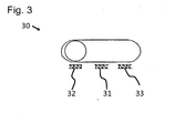
- the actuator 30 is designed as a slide switch.
- the actuator 30 has three switching states, wherein in a first switching state 31 no steam ejection is selected.
- the first switching state 31 here is the in Fig. 3 shown middle switching state.
- the actuator 30 is brought by operation of the first switching state 31 in the second switching state 32.
- the actuating element 30 is brought from the second switching state 32 back into the first switching state 31.
- the second switching state 32 here is the in Fig. 3 shown left switching state. This in Fig.
- actuator 30 is in the second switching state 32, in which the sequence of steam discharges is delivered until the actuator 30 is brought back into the first switching state 31.
- the shifting of the actuating element 30 from the first 31 to the second switching state 32, as well as the displacement of the actuating element 30 from the second 32 to the first switching state 31, is the first operating sequence.
- the actuating element further has a third switching state 33.
- a sliding movement ie by an operator, the user can bring the actuating element in the third switching state 33, wherein the actuating element when released from the third switches to the first switching state 31.
- Such an operation can also be referred to as a touch movement.
- a time-limited sequence of steam ejections which has three steam pulses, is started. After the three steam pulses, this series of steam discharges ends. However, the user can prematurely end this time-limited sequence of steam discharges by a further displacement of the actuating element 30 from the first 31 to the third switching state 33.
- the displacement of the actuating element 30 from the first 31 to the third switching state 33 is the second operating sequence in this case.
- the present invention makes it possible to provide a steam station by means of which the greatest possible pressure of a steam ejection can be achieved with simple structural and cost-effective means.
- a high rate of vaporization can be achieved thereby, whereby the work results, such as e.g. Ironing or cleaning results can be improved.
- an effective operation of the steam station and thus a reduction in energy consumption can be achieved.
- both the total amount of discharged steam can be reduced, and thus energy can be saved, as well as a higher steam discharge rate and thus an improved penetration of the steam into the ironing material can be achieved.
Claims (7)
- Centrale à vapeur (10) pour le traitement à la vapeur d'un article à traiter à la vapeur, comprenant un générateur de vapeur (11) pour la production d'un jet de vapeur, et un organe d'actionnement (30), dans laquelle, lorsque la centrale à vapeur est utilisée pour le traitement de l'article à traiter à la vapeur, une série de jets de vapeur peut être déclenchée et/ou interrompue par utilisation de l'organe d'actionnement (30), cette série durant après le déclenchement jusqu'à ce que l'organe d'actionnement (30) soit à nouveau utilisé, caractérisée en ce que la centrale à vapeur (10) comporte une unité de commande (12) pour la commande du jet de vapeur, qui est adaptée à ce que, par l'utilisation de l'organe d'actionnement (30), une série de jets de vapeur qui se termine après écoulement d'un temps prédéterminé soit déclenchée et/ou interrompue.
- Centrale à vapeur (10) selon la revendication 1, caractérisée en ce que l'unité de commande est adaptée à ce que la série de jets de vapeur qui, après le déclenchement, dure jusqu'à ce que l'organe d'actionnement (30) soit à nouveau utilisé, soit déclenchée et/ou interrompue par une première série d'utilisations de l'organe d'actionnement (30), et que la série de jets de vapeur qui se termine après écoulement d'un temps prédéterminé soit déclenchée et/ou interrompue par une deuxième série d'utilisations de l'organe d'actionnement (30).
- Centrale à vapeur (10) selon l'une des revendications précédentes, caractérisée en ce que l'organe d'actionnement (30) se présente sous forme d'interrupteur.
- Centrale à vapeur (10) selon l'une des revendications précédentes, caractérisée en ce que la centrale à vapeur (10) comporte une soupape (13) grâce à laquelle la série de jets de vapeur peut être produite.
- Centrale à vapeur (10) selon l'une des revendications précédentes, caractérisée en ce que la centrale à vapeur (10) comporte un fer à repasser (20) sur lequel l'organe d'actionnement (30) est disposé.
- Centrale à vapeur (10) selon l'une des revendications précédentes, caractérisée en ce que la centrale à vapeur (10) comporte un organe de réglage (34) pour le réglage du déroulement de la série de jets de vapeur.
- Centrale à vapeur (10) selon l'une des revendications précédentes, caractérisée en ce que la centrale à vapeur (10) comporte un interrupteur de vapeur (35) pour déclencher et/ou interrompre un jet de vapeur continu.
Priority Applications (1)
| Application Number | Priority Date | Filing Date | Title |
|---|---|---|---|
| PL10798809T PL2516723T3 (pl) | 2009-12-22 | 2010-12-22 | Stacja parowa z generatorem pary |
Applications Claiming Priority (3)
| Application Number | Priority Date | Filing Date | Title |
|---|---|---|---|
| DE200910055166 DE102009055166B4 (de) | 2009-12-22 | 2009-12-22 | Dampfstation mit Dampferzeuger |
| ES200931229A ES2387210B1 (es) | 2009-12-22 | 2009-12-22 | Estacion de vapor con generador de vapor |
| PCT/EP2010/070452 WO2011076822A1 (fr) | 2009-12-22 | 2010-12-22 | Centrale vapeur équipée d'un générateur de vapeur |
Publications (2)
| Publication Number | Publication Date |
|---|---|
| EP2516723A1 EP2516723A1 (fr) | 2012-10-31 |
| EP2516723B1 true EP2516723B1 (fr) | 2015-11-25 |
Family
ID=43901577
Family Applications (1)
| Application Number | Title | Priority Date | Filing Date |
|---|---|---|---|
| EP10798809.9A Active EP2516723B1 (fr) | 2009-12-22 | 2010-12-22 | Centrale vapeur équipée d'un générateur de vapeur |
Country Status (5)
| Country | Link |
|---|---|
| EP (1) | EP2516723B1 (fr) |
| ES (1) | ES2555530T3 (fr) |
| PL (1) | PL2516723T3 (fr) |
| PT (1) | PT2516723E (fr) |
| WO (1) | WO2011076822A1 (fr) |
Families Citing this family (4)
| Publication number | Priority date | Publication date | Assignee | Title |
|---|---|---|---|---|
| ES2574578B1 (es) * | 2014-12-19 | 2017-04-11 | Bsh Electrodomésticos España, S.A. | Sistema de generación de vapor, dispositivo de planchado a vapor y procedimiento para accionar un sistema de generación de vapor |
| EP3115501B1 (fr) * | 2015-07-09 | 2022-06-15 | Sda Factory Vitoria Slu | Dispositif de repassage |
| FR3040402B1 (fr) * | 2015-08-27 | 2017-08-11 | Seb Sa | Appareil electromenager pour le traitement du linge a la vapeur comportant un bouton de commande de diffusion de la vapeur |
| CN113981643A (zh) * | 2021-11-18 | 2022-01-28 | 郭彩虹 | 一种熨烫时间自调节的智能熨烫装置 |
Family Cites Families (5)
| Publication number | Priority date | Publication date | Assignee | Title |
|---|---|---|---|---|
| US5010664A (en) | 1988-11-18 | 1991-04-30 | Matsushita Electric Industrial Co., Ltd. | Steam iron having a solenoid driven pump and heated evaporation chamber for providing steam and operable for further providing extra steam at specified intervals |
| NL8900749A (nl) * | 1989-03-28 | 1990-10-16 | Philips Nv | Stoomstrijkijzer. |
| EP0423540B2 (fr) | 1989-10-20 | 1996-07-10 | S.T.E.M. S.R.L. | Générateur de vapeur à usage domestique et industriel |
| FR2710351B1 (fr) | 1993-09-24 | 1995-11-24 | Seb Sa | Procédé de repassage d'un article textile à gestion automatique du cycle de vapeur, et appareil de repassage pour la mise en Óoeuvre dudit procédé. |
| DE19614511C1 (de) | 1996-04-12 | 1997-01-23 | Rowenta Werke Gmbh | Dampfbügelstation |
-
2010
- 2010-12-22 ES ES10798809.9T patent/ES2555530T3/es active Active
- 2010-12-22 WO PCT/EP2010/070452 patent/WO2011076822A1/fr active Application Filing
- 2010-12-22 PT PT107988099T patent/PT2516723E/pt unknown
- 2010-12-22 PL PL10798809T patent/PL2516723T3/pl unknown
- 2010-12-22 EP EP10798809.9A patent/EP2516723B1/fr active Active
Also Published As
| Publication number | Publication date |
|---|---|
| PT2516723E (pt) | 2016-03-22 |
| EP2516723A1 (fr) | 2012-10-31 |
| WO2011076822A1 (fr) | 2011-06-30 |
| ES2555530T3 (es) | 2016-01-04 |
| PL2516723T3 (pl) | 2016-04-29 |
Similar Documents
| Publication | Publication Date | Title |
|---|---|---|
| EP2516723B1 (fr) | Centrale vapeur équipée d'un générateur de vapeur | |
| EP2006432B1 (fr) | Procédé de fonctionnement d'une machine de traitement du linge à l'aide d'un dispositif de production de vapeur et machine de traitement du linge | |
| DE102011006766B4 (de) | Dampferzeuger und Verfahren zum Steuern der Wasserzufuhr des Dampferzeugers | |
| CH687392A5 (de) | Dampfbuegeleisen. | |
| DE102009055163B4 (de) | Dampfstation mit Temperatureinstellmittel | |
| EP3170940B1 (fr) | Douche-wc comprenant un chauffe-eau | |
| DE102009055166B4 (de) | Dampfstation mit Dampferzeuger | |
| EP2402498A1 (fr) | Procédé de fonctionnement d'une machine de traitement du linge à l'aide d'un dispositif de production de vapeur et machine de traitement du linge | |
| DE19614511C1 (de) | Dampfbügelstation | |
| EP2516721A2 (fr) | Centrale vapeur comportant un moyen de réglage de température | |
| EP3846949A1 (fr) | Appareil de nettoyage à l'eau chaude et procédé destiné à faire fonctionner un appareil de nettoyage à l'eau chaude | |
| EP2143366B1 (fr) | Procédé de dosage d'un premier moyen de traitement et d'un second moyen de traitement dans le récipient de nettoyage d'un lave-vaisselle | |
| EP3740106B1 (fr) | Dispositif pour faire mousser du lait | |
| EP3141668B1 (fr) | Wc-douche dote d'un chauffe-eau instantane et ballon d'eau chaude | |
| DE1115706B (de) | Waschverfahren und automatische Waschmaschine zu seiner Durchfuehrung | |
| DE102009055167B4 (de) | Dampferzeuger mit Betätigungselement | |
| DE102011084408B4 (de) | Dampferzeugendes Haushaltsgerät mit Nassdampffunktion | |
| EP2516722B1 (fr) | Générateur de vapeur comportant un élément d'actionnement | |
| EP3315650A1 (fr) | Système d'alimentation en eau et système d'incorporation de la composition détergente pour un lave-linge | |
| DE102012219292A1 (de) | Bügeleisen mit Betriebsmodus zum Verringern oder Vermeiden einer Glanzentstehung | |
| EP2963173B1 (fr) | Procédé de nettoyage d'un fer à repasser à vapeur et d'une centrale vapeur | |
| DE102011081375B4 (de) | Elektrobügelgerät, insbesondere Dampfbügeleisen oder Dampfbügelstation | |
| DE102010041342B4 (de) | Elektrisch beheizbares Gerät, insbesondere Bügeleisen, und Verfahren zur Steuerung eines solchen Geräts | |
| EP3444397A1 (fr) | Appareil à repasser et procédé de commande d'une unité de chauffage d'un appareil à repasser | |
| EP4006227B1 (fr) | Fer à vapeur et son procédé de fonctionnement |
Legal Events
| Date | Code | Title | Description |
|---|---|---|---|
| PUAI | Public reference made under article 153(3) epc to a published international application that has entered the european phase |
Free format text: ORIGINAL CODE: 0009012 |
|
| 17P | Request for examination filed |
Effective date: 20120723 |
|
| AK | Designated contracting states |
Kind code of ref document: A1 Designated state(s): AL AT BE BG CH CY CZ DE DK EE ES FI FR GB GR HR HU IE IS IT LI LT LU LV MC MK MT NL NO PL PT RO RS SE SI SK SM TR |
|
| DAX | Request for extension of the european patent (deleted) | ||
| 17Q | First examination report despatched |
Effective date: 20140929 |
|
| RAP1 | Party data changed (applicant data changed or rights of an application transferred) |
Owner name: BSH HAUSGERAETE GMBH |
|
| GRAP | Despatch of communication of intention to grant a patent |
Free format text: ORIGINAL CODE: EPIDOSNIGR1 |
|
| INTG | Intention to grant announced |
Effective date: 20150701 |
|
| GRAS | Grant fee paid |
Free format text: ORIGINAL CODE: EPIDOSNIGR3 |
|
| GRAA | (expected) grant |
Free format text: ORIGINAL CODE: 0009210 |
|
| AK | Designated contracting states |
Kind code of ref document: B1 Designated state(s): AL AT BE BG CH CY CZ DE DK EE ES FI FR GB GR HR HU IE IS IT LI LT LU LV MC MK MT NL NO PL PT RO RS SE SI SK SM TR |
|
| REG | Reference to a national code |
Ref country code: GB Ref legal event code: FG4D Free format text: NOT ENGLISH |
|
| REG | Reference to a national code |
Ref country code: CH Ref legal event code: EP |
|
| REG | Reference to a national code |
Ref country code: AT Ref legal event code: REF Ref document number: 762682 Country of ref document: AT Kind code of ref document: T Effective date: 20151215 |
|
| REG | Reference to a national code |
Ref country code: IE Ref legal event code: FG4D Free format text: LANGUAGE OF EP DOCUMENT: GERMAN |
|
| REG | Reference to a national code |
Ref country code: FR Ref legal event code: PLFP Year of fee payment: 6 |
|
| REG | Reference to a national code |
Ref country code: DE Ref legal event code: R096 Ref document number: 502010010716 Country of ref document: DE |
|
| REG | Reference to a national code |
Ref country code: ES Ref legal event code: FG2A Ref document number: 2555530 Country of ref document: ES Kind code of ref document: T3 Effective date: 20160104 |
|
| REG | Reference to a national code |
Ref country code: PT Ref legal event code: SC4A Free format text: AVAILABILITY OF NATIONAL TRANSLATION Effective date: 20160215 |
|
| REG | Reference to a national code |
Ref country code: LT Ref legal event code: MG4D |
|
| REG | Reference to a national code |
Ref country code: NL Ref legal event code: FP |
|
| PG25 | Lapsed in a contracting state [announced via postgrant information from national office to epo] |
Ref country code: IS Free format text: LAPSE BECAUSE OF FAILURE TO SUBMIT A TRANSLATION OF THE DESCRIPTION OR TO PAY THE FEE WITHIN THE PRESCRIBED TIME-LIMIT Effective date: 20160325 Ref country code: NO Free format text: LAPSE BECAUSE OF FAILURE TO SUBMIT A TRANSLATION OF THE DESCRIPTION OR TO PAY THE FEE WITHIN THE PRESCRIBED TIME-LIMIT Effective date: 20160225 Ref country code: LT Free format text: LAPSE BECAUSE OF FAILURE TO SUBMIT A TRANSLATION OF THE DESCRIPTION OR TO PAY THE FEE WITHIN THE PRESCRIBED TIME-LIMIT Effective date: 20151125 Ref country code: HR Free format text: LAPSE BECAUSE OF FAILURE TO SUBMIT A TRANSLATION OF THE DESCRIPTION OR TO PAY THE FEE WITHIN THE PRESCRIBED TIME-LIMIT Effective date: 20151125 |
|
| PG25 | Lapsed in a contracting state [announced via postgrant information from national office to epo] |
Ref country code: LV Free format text: LAPSE BECAUSE OF FAILURE TO SUBMIT A TRANSLATION OF THE DESCRIPTION OR TO PAY THE FEE WITHIN THE PRESCRIBED TIME-LIMIT Effective date: 20151125 Ref country code: FI Free format text: LAPSE BECAUSE OF FAILURE TO SUBMIT A TRANSLATION OF THE DESCRIPTION OR TO PAY THE FEE WITHIN THE PRESCRIBED TIME-LIMIT Effective date: 20151125 Ref country code: SE Free format text: LAPSE BECAUSE OF FAILURE TO SUBMIT A TRANSLATION OF THE DESCRIPTION OR TO PAY THE FEE WITHIN THE PRESCRIBED TIME-LIMIT Effective date: 20151125 Ref country code: BE Free format text: LAPSE BECAUSE OF NON-PAYMENT OF DUE FEES Effective date: 20151231 Ref country code: RS Free format text: LAPSE BECAUSE OF FAILURE TO SUBMIT A TRANSLATION OF THE DESCRIPTION OR TO PAY THE FEE WITHIN THE PRESCRIBED TIME-LIMIT Effective date: 20151125 |
|
| PG25 | Lapsed in a contracting state [announced via postgrant information from national office to epo] |
Ref country code: CZ Free format text: LAPSE BECAUSE OF FAILURE TO SUBMIT A TRANSLATION OF THE DESCRIPTION OR TO PAY THE FEE WITHIN THE PRESCRIBED TIME-LIMIT Effective date: 20151125 |
|
| REG | Reference to a national code |
Ref country code: CH Ref legal event code: PL |
|
| REG | Reference to a national code |
Ref country code: DE Ref legal event code: R097 Ref document number: 502010010716 Country of ref document: DE |
|
| PG25 | Lapsed in a contracting state [announced via postgrant information from national office to epo] |
Ref country code: DK Free format text: LAPSE BECAUSE OF FAILURE TO SUBMIT A TRANSLATION OF THE DESCRIPTION OR TO PAY THE FEE WITHIN THE PRESCRIBED TIME-LIMIT Effective date: 20151125 Ref country code: SK Free format text: LAPSE BECAUSE OF FAILURE TO SUBMIT A TRANSLATION OF THE DESCRIPTION OR TO PAY THE FEE WITHIN THE PRESCRIBED TIME-LIMIT Effective date: 20151125 Ref country code: EE Free format text: LAPSE BECAUSE OF FAILURE TO SUBMIT A TRANSLATION OF THE DESCRIPTION OR TO PAY THE FEE WITHIN THE PRESCRIBED TIME-LIMIT Effective date: 20151125 Ref country code: RO Free format text: LAPSE BECAUSE OF FAILURE TO SUBMIT A TRANSLATION OF THE DESCRIPTION OR TO PAY THE FEE WITHIN THE PRESCRIBED TIME-LIMIT Effective date: 20151125 Ref country code: SM Free format text: LAPSE BECAUSE OF FAILURE TO SUBMIT A TRANSLATION OF THE DESCRIPTION OR TO PAY THE FEE WITHIN THE PRESCRIBED TIME-LIMIT Effective date: 20151125 |
|
| REG | Reference to a national code |
Ref country code: IE Ref legal event code: MM4A |
|
| PG25 | Lapsed in a contracting state [announced via postgrant information from national office to epo] |
Ref country code: MC Free format text: LAPSE BECAUSE OF FAILURE TO SUBMIT A TRANSLATION OF THE DESCRIPTION OR TO PAY THE FEE WITHIN THE PRESCRIBED TIME-LIMIT Effective date: 20151125 |
|
| PLBE | No opposition filed within time limit |
Free format text: ORIGINAL CODE: 0009261 |
|
| STAA | Information on the status of an ep patent application or granted ep patent |
Free format text: STATUS: NO OPPOSITION FILED WITHIN TIME LIMIT |
|
| PG25 | Lapsed in a contracting state [announced via postgrant information from national office to epo] |
Ref country code: LI Free format text: LAPSE BECAUSE OF NON-PAYMENT OF DUE FEES Effective date: 20151231 Ref country code: IE Free format text: LAPSE BECAUSE OF NON-PAYMENT OF DUE FEES Effective date: 20151222 Ref country code: CH Free format text: LAPSE BECAUSE OF NON-PAYMENT OF DUE FEES Effective date: 20151231 |
|
| 26N | No opposition filed |
Effective date: 20160826 |
|
| PG25 | Lapsed in a contracting state [announced via postgrant information from national office to epo] |
Ref country code: SI Free format text: LAPSE BECAUSE OF FAILURE TO SUBMIT A TRANSLATION OF THE DESCRIPTION OR TO PAY THE FEE WITHIN THE PRESCRIBED TIME-LIMIT Effective date: 20151125 |
|
| REG | Reference to a national code |
Ref country code: FR Ref legal event code: PLFP Year of fee payment: 7 |
|
| REG | Reference to a national code |
Ref country code: AT Ref legal event code: MM01 Ref document number: 762682 Country of ref document: AT Kind code of ref document: T Effective date: 20151222 |
|
| PG25 | Lapsed in a contracting state [announced via postgrant information from national office to epo] |
Ref country code: HU Free format text: LAPSE BECAUSE OF FAILURE TO SUBMIT A TRANSLATION OF THE DESCRIPTION OR TO PAY THE FEE WITHIN THE PRESCRIBED TIME-LIMIT; INVALID AB INITIO Effective date: 20101222 Ref country code: AT Free format text: LAPSE BECAUSE OF NON-PAYMENT OF DUE FEES Effective date: 20151222 Ref country code: BG Free format text: LAPSE BECAUSE OF FAILURE TO SUBMIT A TRANSLATION OF THE DESCRIPTION OR TO PAY THE FEE WITHIN THE PRESCRIBED TIME-LIMIT Effective date: 20151125 |
|
| PG25 | Lapsed in a contracting state [announced via postgrant information from national office to epo] |
Ref country code: GR Free format text: LAPSE BECAUSE OF FAILURE TO SUBMIT A TRANSLATION OF THE DESCRIPTION OR TO PAY THE FEE WITHIN THE PRESCRIBED TIME-LIMIT Effective date: 20151125 Ref country code: CY Free format text: LAPSE BECAUSE OF FAILURE TO SUBMIT A TRANSLATION OF THE DESCRIPTION OR TO PAY THE FEE WITHIN THE PRESCRIBED TIME-LIMIT Effective date: 20151125 |
|
| PG25 | Lapsed in a contracting state [announced via postgrant information from national office to epo] |
Ref country code: MT Free format text: LAPSE BECAUSE OF FAILURE TO SUBMIT A TRANSLATION OF THE DESCRIPTION OR TO PAY THE FEE WITHIN THE PRESCRIBED TIME-LIMIT Effective date: 20151125 |
|
| PG25 | Lapsed in a contracting state [announced via postgrant information from national office to epo] |
Ref country code: LU Free format text: LAPSE BECAUSE OF NON-PAYMENT OF DUE FEES Effective date: 20151222 |
|
| REG | Reference to a national code |
Ref country code: FR Ref legal event code: PLFP Year of fee payment: 8 |
|
| PG25 | Lapsed in a contracting state [announced via postgrant information from national office to epo] |
Ref country code: MK Free format text: LAPSE BECAUSE OF FAILURE TO SUBMIT A TRANSLATION OF THE DESCRIPTION OR TO PAY THE FEE WITHIN THE PRESCRIBED TIME-LIMIT Effective date: 20151125 |
|
| PG25 | Lapsed in a contracting state [announced via postgrant information from national office to epo] |
Ref country code: AL Free format text: LAPSE BECAUSE OF FAILURE TO SUBMIT A TRANSLATION OF THE DESCRIPTION OR TO PAY THE FEE WITHIN THE PRESCRIBED TIME-LIMIT Effective date: 20151125 |
|
| REG | Reference to a national code |
Ref country code: DE Ref legal event code: R082 Ref document number: 502010010716 Country of ref document: DE Representative=s name: RGTH RICHTER GERBAULET THIELEMANN HOFMANN PATE, DE Ref country code: DE Ref legal event code: R081 Ref document number: 502010010716 Country of ref document: DE Owner name: SDA FACTORY VITORIA SLU, VITORIA GASTELZ, ES Free format text: FORMER OWNER: BSH HAUSGERAETE GMBH, 81739 MUENCHEN, DE |
|
| PGFP | Annual fee paid to national office [announced via postgrant information from national office to epo] |
Ref country code: PT Payment date: 20191217 Year of fee payment: 10 Ref country code: NL Payment date: 20191217 Year of fee payment: 10 |
|
| REG | Reference to a national code |
Ref country code: ES Ref legal event code: PC2A Owner name: SDA FACTORY VITORIA, SLU Effective date: 20200129 |
|
| PGFP | Annual fee paid to national office [announced via postgrant information from national office to epo] |
Ref country code: IT Payment date: 20191216 Year of fee payment: 10 Ref country code: PL Payment date: 20191210 Year of fee payment: 10 |
|
| REG | Reference to a national code |
Ref country code: GB Ref legal event code: 732E Free format text: REGISTERED BETWEEN 20200716 AND 20200722 |
|
| PG25 | Lapsed in a contracting state [announced via postgrant information from national office to epo] |
Ref country code: PT Free format text: LAPSE BECAUSE OF NON-PAYMENT OF DUE FEES Effective date: 20210622 |
|
| REG | Reference to a national code |
Ref country code: NL Ref legal event code: MM Effective date: 20210101 |
|
| PG25 | Lapsed in a contracting state [announced via postgrant information from national office to epo] |
Ref country code: NL Free format text: LAPSE BECAUSE OF NON-PAYMENT OF DUE FEES Effective date: 20210101 |
|
| PG25 | Lapsed in a contracting state [announced via postgrant information from national office to epo] |
Ref country code: IT Free format text: LAPSE BECAUSE OF NON-PAYMENT OF DUE FEES Effective date: 20201222 |
|
| PGFP | Annual fee paid to national office [announced via postgrant information from national office to epo] |
Ref country code: GB Payment date: 20211215 Year of fee payment: 12 Ref country code: DE Payment date: 20211209 Year of fee payment: 12 |
|
| PG25 | Lapsed in a contracting state [announced via postgrant information from national office to epo] |
Ref country code: TR Free format text: LAPSE BECAUSE OF NON-PAYMENT OF DUE FEES Effective date: 20201222 |
|
| PG25 | Lapsed in a contracting state [announced via postgrant information from national office to epo] |
Ref country code: PL Free format text: LAPSE BECAUSE OF NON-PAYMENT OF DUE FEES Effective date: 20201222 |
|
| PGFP | Annual fee paid to national office [announced via postgrant information from national office to epo] |
Ref country code: ES Payment date: 20230111 Year of fee payment: 13 |
|
| REG | Reference to a national code |
Ref country code: DE Ref legal event code: R119 Ref document number: 502010010716 Country of ref document: DE |
|
| GBPC | Gb: european patent ceased through non-payment of renewal fee |
Effective date: 20221222 |
|
| PG25 | Lapsed in a contracting state [announced via postgrant information from national office to epo] |
Ref country code: GB Free format text: LAPSE BECAUSE OF NON-PAYMENT OF DUE FEES Effective date: 20221222 Ref country code: DE Free format text: LAPSE BECAUSE OF NON-PAYMENT OF DUE FEES Effective date: 20230701 |
|
| PGFP | Annual fee paid to national office [announced via postgrant information from national office to epo] |
Ref country code: FR Payment date: 20231212 Year of fee payment: 14 |
|
| PGFP | Annual fee paid to national office [announced via postgrant information from national office to epo] |
Ref country code: ES Payment date: 20240104 Year of fee payment: 14 |