EP2516723B1 - Steam station comprising a steam generator - Google Patents
Steam station comprising a steam generator Download PDFInfo
- Publication number
- EP2516723B1 EP2516723B1 EP10798809.9A EP10798809A EP2516723B1 EP 2516723 B1 EP2516723 B1 EP 2516723B1 EP 10798809 A EP10798809 A EP 10798809A EP 2516723 B1 EP2516723 B1 EP 2516723B1
- Authority
- EP
- European Patent Office
- Prior art keywords
- steam
- sequence
- station
- discharges
- actuating element
- Prior art date
- Legal status (The legal status is an assumption and is not a legal conclusion. Google has not performed a legal analysis and makes no representation as to the accuracy of the status listed.)
- Active
Links
- XEEYBQQBJWHFJM-UHFFFAOYSA-N Iron Chemical compound [Fe] XEEYBQQBJWHFJM-UHFFFAOYSA-N 0.000 claims description 64
- 229910052742 iron Inorganic materials 0.000 claims description 32
- 238000000034 method Methods 0.000 claims description 18
- 230000008569 process Effects 0.000 claims description 15
- 230000008020 evaporation Effects 0.000 claims 2
- 238000001704 evaporation Methods 0.000 claims 2
- 238000010409 ironing Methods 0.000 description 40
- 238000004140 cleaning Methods 0.000 description 11
- 238000010438 heat treatment Methods 0.000 description 7
- 239000000463 material Substances 0.000 description 7
- XLYOFNOQVPJJNP-UHFFFAOYSA-N water Substances O XLYOFNOQVPJJNP-UHFFFAOYSA-N 0.000 description 7
- 230000008859 change Effects 0.000 description 5
- 238000005265 energy consumption Methods 0.000 description 5
- 238000003825 pressing Methods 0.000 description 5
- 230000009467 reduction Effects 0.000 description 5
- 239000012141 concentrate Substances 0.000 description 4
- 230000008901 benefit Effects 0.000 description 3
- 238000006073 displacement reaction Methods 0.000 description 3
- 239000007788 liquid Substances 0.000 description 3
- 238000011161 development Methods 0.000 description 2
- 230000018109 developmental process Effects 0.000 description 2
- 238000010586 diagram Methods 0.000 description 2
- 238000005485 electric heating Methods 0.000 description 2
- 230000006872 improvement Effects 0.000 description 2
- 230000003993 interaction Effects 0.000 description 2
- 230000035515 penetration Effects 0.000 description 2
- 238000009834 vaporization Methods 0.000 description 2
- 230000008016 vaporization Effects 0.000 description 2
- 230000005540 biological transmission Effects 0.000 description 1
- 238000012790 confirmation Methods 0.000 description 1
- 230000001419 dependent effect Effects 0.000 description 1
- 238000001035 drying Methods 0.000 description 1
- 230000000694 effects Effects 0.000 description 1
- 230000005611 electricity Effects 0.000 description 1
- 230000000670 limiting effect Effects 0.000 description 1
- 238000007726 management method Methods 0.000 description 1
- 230000001172 regenerating effect Effects 0.000 description 1
- 238000010025 steaming Methods 0.000 description 1
- 230000002123 temporal effect Effects 0.000 description 1
- 239000004753 textile Substances 0.000 description 1
Images

Classifications
-
- D—TEXTILES; PAPER
- D06—TREATMENT OF TEXTILES OR THE LIKE; LAUNDERING; FLEXIBLE MATERIALS NOT OTHERWISE PROVIDED FOR
- D06F—LAUNDERING, DRYING, IRONING, PRESSING OR FOLDING TEXTILE ARTICLES
- D06F75/00—Hand irons
- D06F75/08—Hand irons internally heated by electricity
- D06F75/10—Hand irons internally heated by electricity with means for supplying steam to the article being ironed
- D06F75/12—Hand irons internally heated by electricity with means for supplying steam to the article being ironed the steam being produced from water supplied to the iron from an external source
-
- F—MECHANICAL ENGINEERING; LIGHTING; HEATING; WEAPONS; BLASTING
- F22—STEAM GENERATION
- F22B—METHODS OF STEAM GENERATION; STEAM BOILERS
- F22B1/00—Methods of steam generation characterised by form of heating method
- F22B1/28—Methods of steam generation characterised by form of heating method in boilers heated electrically
- F22B1/284—Methods of steam generation characterised by form of heating method in boilers heated electrically with water in reservoirs
- F22B1/285—Methods of steam generation characterised by form of heating method in boilers heated electrically with water in reservoirs the water being fed by a pump to the reservoirs
Definitions
- the present invention relates to a steam station for steaming a Bedampfungsguts with a steam generator for generating a steam ejection, and an actuating element.
- a steam ironing station with a steam station and a steam iron
- the steam station having a steam generator.
- the steam generated in the steam generator is passed through a steam line in the steam iron.
- the steam is routed through steam guides in the iron soleplate heated by a heater.
- a feed pump is provided, which promotes water from a water tank directly into the steam line, whereby it is achieved that the exiting at the soleplate steam has a high humidity.
- the invention has for its object to provide a comparison with the prior art improved steam station.
- a steam station is to be provided in which a steam discharge with the highest possible pressure can be achieved.
- the steam discharge rate of a steam ejection should be increased.
- a steam station is to be provided, through which a reduction in energy consumption is possible.
- a time-unlimited sequence of steam surges is a consequence that advantageously runs after starting so long until the actuator again is operated to end the series of steam discharges.
- a time-limited sequence is understood to mean a sequence which ends after a predetermined time has elapsed, so that the steam generator no longer gives off a series of steam discharges after the predetermined time has elapsed. However, this does not mean that the steam generator does not give off any steam after passing through the time-limited sequence.
- the temporally limited sequence that is after the expiration of the predetermined time, still a constant output of steam can be delivered.
- the operation of the steam generator can be simplified by a time-limited sequence of steam discharges, since the user during use, eg during a ironing operation, the time-limited sequence can start by operating the actuator without having to end this by re-operating again since this ends advantageously after the expiration of the predetermined time.
- the user can concentrate better on the actual work process, such as an ironing or cleaning process.
- a steam station is to be understood as a system for providing and / or delivering steam in order to be able to treat a material to be steamed.
- the steam generator can generate at least one steam output.
- the steam station can be used, for example, for the care of clothing, and be designed for this purpose, for example, as ironing, ironing station, steam straightener, so-called steam brush or steam brush.
- a steam station according to the invention can also be used for cleaning purposes, and be designed, for example, as a steam cleaner.
- a series of steam ejections is a sequence in which phases alternate with higher steam ejection rates and phases with lower or no steam ejection rates. The phases with a higher steam discharge rate are considered as steam discharges from the series of steam discharges.
- a series of steam bursts may also be referred to as a result of steam pulses.
- a steam discharge rate is the amount of steam that is released in a given time unit. Usually, the steam discharge rate is measured in grams per minute (g / min).
- the sequence of the sequence ie the change of phases with higher and phases with lower or no steam discharge rate, as well as the duration of the phases, is not affected. That the sequence of steam discharges is startable and / or terminable, while the steam station for processing the Bedampfungsguts means that a user does not have to interrupt the handling in order to start and / or end the sequence.
- handling is here to be understood the activity of a user that the user carries out in order to process the material to be steamed. This can be, for example, the guiding of an iron or a cleaning device.
- the steam ejection rate of the steam ejections can be increased by the sequence of steam ejections.
- the duration of each steam ejection may advantageously be so short that a pressure drop during steam ejection can be minimized, and thus a higher amount of steam can be transported during steam ejection.
- the vapor pressure dropped off during a steam discharge between the steam discharges can be regenerated again, that is, increased to the initial pressure value.
- the initial pressure value is the value of the vapor pressure prevailing at the beginning of a steam discharge, ie before the beginning of a pressure drop. Usually, the initial pressure value is the highest vapor pressure of a vapor ejection.
- each steam ejection of a sequence has the same temporal vapor pressure profile, and thus an equally high steam ejection rate.
- an improvement of the working results can be achieved by the invention, since in the sequence of steam ejections, a higher steam discharge rate of the steam ejections can be achieved. As a result, the vapor may e.g. better penetrate the material to be ironed, or remove dirt from a surface better. Furthermore, due to the succession of steam discharges, an improved sliding of an iron on the ironing material can be achieved due to the constantly high vapor pressure of the steam ejections of the sequence.
- the user can select at any time during handling for processing the Bedampfungsguts, eg during ironing or cleaning process, whether he wants to operate the steam station with or without dispensing a series of steam discharges.
- an ironing or cleaning operation begins by engaging a portion of the steam station, e.g. an iron or a cleaning device, and ends with the release of the same.
- a portion of the steam station e.g. an iron or a cleaning device
- this energy can be saved, since the steam station can be operated without dispensing a series of steam discharges.
- the sequence of steam discharges can be started and / or terminated by the user via an operation of the actuating element, so that the user can start and / or terminate the sequence as required. Furthermore, it is advantageously achievable that the user does not have to control the sequence of the sequence, and thus is better able to concentrate on the working process, e.g. can concentrate a ironing or cleaning process.
- the duration of steam ejection of the series of steam ejections is so short that the pressure drop during steam ejection does not exceed 15%, more preferably 10%, most preferably 5%.
- the time period between successive steam ejections is at least 0.5 seconds, more preferably at least 1.0 seconds.
- each steam ejection has a maximum duration of 1.0 second, particularly preferably of 0.5 second maximum.
- the actuating element is operated by a tactile movement, wherein the actuating element can be brought by the tactile movement of a first switching state in a second switching state, and after completion of the tactile movement of the second in the first switching state.
- the actuating element has an elastic element, by means of which the actuating element can be brought from the second to the first switching state after the end of the scanning movement.
- the tactile movement may e.g. be a tap, press or pull and then release the actuator.
- the sequence of steam discharges can be started and / or terminated by the touch movement.
- the series of steam discharges e.g. started by a first touch movement, and terminated by a first following the second touch movement.
- no additional interaction of the user with the actuator is required to run the sequence of steam discharges. This may facilitate the ironing operation, since during the ironing operation, the user can start the series of steam discharges by a simple operation of the operating member, and concentrate on the actual ironing operation during the delivery of the steam discharges.
- the user can end the sequence of steam discharges at any time by re-operation of the actuating element.
- the actuator is brought by operation from a first switching state to a second switching state to start the series of steam discharges, and brought from the second to the first switching state to terminate the series of steam discharges.
- the actuator may be pushed or pulled to be brought from the first to the second state, and released to be brought from the second to the first state.
- the user while the user is in contact with the actuator during delivery of the train of vapor ejections, the user does not affect the course of the phases of the sequence through its interaction with the actuator.
- This may advantageously allow simplification of the operation for controlling the sequence of steam discharges, since the steam discharges are delivered only in the time in which the user interacts with the actuating element, for example by holding or pulling it.
- can an improvement of the ironing results are possible because the user with uneven wrinkling of the ironing the delivery of the steam ejections does not have to activate during the entire ironing process, but can selectively switch on and off.
- the actuating element is brought by a tactile movement in the first and / or second state, wherein the actuating element by a latching device in the respective position remains, and does not return to the previous state.
- a part of the actuating element is displaced during the operation of the actuating element in order to change the switching state of the actuating element between the first and second switching state.
- Such an actuator may e.g. be designed as a slide switch.
- the operation of the actuator is against a force, e.g. a spring force of an elastically deformable element, whereby accidental operation of the actuating element can be avoided.
- the sequence of steam discharges can be started and / or terminated by a first operating sequence of the actuating element.
- Under an operating sequence of the actuating element are caused by an operation to be understood, temporally successive, divergent states of the actuating element.
- the first operating sequence consists of a single touch movement. This means that the actuating element is operated by a tactile movement in order to start and / or end the series of steam ejections. This tactile movement can be compared with a "single click" when operating a computer mouse.
- the actuating element can be brought by operation in a third switching state to start the temporally limited sequence of steam ejections and / or to end.
- the time-limited sequence can also be terminated before the expiry of the predetermined time by operating the actuating element.
- the time-limited sequence has a fixed number of steam bursts.
- the predetermined time of the time-limited sequence is dimensioned in this embodiment so that after this time a fixed number of steam bursts was delivered.
- the user may also, if he has operated the actuator incorrectly, or no longer requires the steam ejections, terminate the time-limited sequence of steam ejections prematurely by re-operating the actuator.
- a time-limited sequence of steam discharges can be started and / or terminated by a second operating sequence of the actuating element.
- Under an operating sequence of the actuating element are caused by an operation to be understood, temporally successive, divergent states of the actuating element.
- the second operating sequence of two scanning movements of the actuating element wherein the time interval between the touch movements does not exceed a predetermined period of time.
- the actuating element is operated by a double touch movement in order to start and / or end the time-limited sequence of steam discharges.
- the time between the two tactile movements may not exceed a fixed period of time.
- This two-time tactile movement can be compared with a "double-click" when operating a computer mouse.
- the time interval between the individual scanning movements of the second operating sequence is particularly preferably a maximum of only one second, particularly preferably a maximum of only half a second.
- the two-time touch movement of the second sequence of operation a simple operation can be made possible because the user of such a sequence can already be known from the operation of a computer with a mouse.
- the steam station has a control unit for controlling the steam output.
- the actuating element is designed as a switch.
- the actuating element is designed as a push-button.
- the key switch may e.g. be pressed or pulled during an operation.
- the key switch can also be designed as a sensor switch, which is touched during operation. This touching can also be considered as a tactile movement.
- the key switch can be brought by operation in a first and second switching position.
- the first and / or second sequence of operations on an operating element designed as a push-button switch is easy to carry out, wherein the push-button switch can be operated by one-time or by two operations briefly in quick succession.
- such a key switch is also during a work operation, e.g. easy to operate during ironing or cleaning.
- the actuating element is designed as a slide switch.
- the slide switch may e.g. two switching states, a first and a second switching state, wherein e.g. no steam output or a constant steam output is selected by the first switching state, and the delivery of a series of steam discharges can be selected by the second switching state.
- the operation of the steam station selected by the second switching state may also be referred to as steam pulse operation.
- the actuating element designed as a slide switch has a third switching state, by means of which a time-limited sequence of steam discharges can be started and / or terminated.
- the third position is a tactile position. This means that the actuator returns to the previous position after operation, e.g. changes to the first or second position.
- the operating element designed as a slide switch has all three switching states, first, second and third switching state.
- control unit is arranged on the steam generator.
- control unit is connected to the actuating element.
- control unit is connected via a line to the actuating element.
- the steam station has a valve, by means of which the sequence of steam discharges can be generated.
- the valve is arranged on the steam generator.
- the valve is connectable to the line of an iron.
- vapor pressure can be controlled through the hose to the iron, so as to be able to produce a steam output and / or a series of steam discharges.
- the valve can be brought into a position between the open and the closed position, so that through the valve and the exiting amount of steam can be controlled.
- the valve can produce any desired series of steam discharges, in which phases alternate with higher steam discharge rates and phases with lower steam discharge rates.
- the steam generator to a steam boiler for generating a vapor pressure, which is connectable via the valve with the hose of an iron.
- the valve is controllable via the control unit. This makes it achievable that any sequence of steam discharges can be generated.
- the valve is designed as an electrovalve.
- the steam station comprises an iron on which the actuating element is arranged.
- the steam station is designed as an ironing station.
- the iron is connected via a line, particularly preferably via a hose to the steam generator in order to supply the iron with steam for ironing can.
- This makes it possible for the user to easily start and / or terminate the sequence of steam discharges during the ironing process, so that an improved operation of the steam station can be achieved.
- ironing begins with the touch of the iron, and ends with the release of the iron.
- a series of steam discharges can be started and / or terminated during a pressing operation during normal operation of the steam station.
- sequence of steam discharges can also be started and / or terminated before or after an ironing process.
- sequence of steam discharges does not start with the touch of the iron and is not terminated with the release of the iron, so that the user can be enabled during the ironing of Ironing material as needed, eg to smooth out heavily wrinkled areas of the ironing stock, to start and / or end the sequence of steam ejections.
- the actuating element can be connected by lines to the steam generator.
- the confirmation element can be connected by lines to the control unit. Through the lines, a transmission of the switching state of the actuating element to the steam generator and / or the control unit can be achieved.
- the steam station has an adjusting element for setting the sequence of the sequence of steam discharges.
- the adjustment element allows the user to start and / or during a work operation, e.g. during an ironing or cleaning operation, adjust the sequence of the sequence of steam discharges to make them e.g. to be able to adapt to the ironing or a surface to be cleaned.
- the frequency of the sequence of steam ejections can be set by the adjusting element.
- the period of the sequence of steam ejections is variable by the setting element, wherein the period corresponds to the time interval between the beginning of two successive steam ejections.
- a particularly preferred adjustment is designed as a rotary switch.
- the frequency of the sequence of steam discharges via the rotation of the rotary switch is adjustable.
- the duration of the individual steam ejections of the sequence of steam ejections is constant.
- the invention also includes embodiments in which by the adjusting the time duration of a steam ejection and the time duration between successive steam ejections are changed by the adjusting element in a fixed ratio.
- the ratio between the duration of a steam ejection and the time duration between successive steam ejections is 0.5.
- the steam station has a steam switch for starting and / or stopping a continuous steam ejection.
- the steam switch By operating the steam switch, the user can start and / or stop the delivery of a continuous steam discharge, with the same possibilities for operating the steam switch as for operating the operating element.
- the steam ejection rate of a continuous steam ejection is selectable by the steam switch.
- the steam switch can be brought into at least one position deviating from the zero position by operation of a zero position, in which no continuous steam emission is emitted. By deviating from the zero position, the steam ejection rate of the continuous steam ejection can be selected.
- such a steam switch is designed as a rotary switch.
- the delivery of the continuous steam discharge by operating the actuating element can be terminated.
- the continuous steam discharge is stopped and the sequence of steam discharges is started.
- the continuous steam discharge continues.
- the invention also includes embodiments in which the continuous discharge of steam is not continued after completion of the sequence of steam discharges.
- the steam generator to a steam boiler.
- the steam boiler can be used to generate the steam pressure necessary to produce a steam output.
- the steam boiler has an interior whose volume is between 250ml and 1000ml.
- the steam generator to a refill system.
- the boiler can be filled by the refill system with a liquid, for example with water.
- the refill system has a reservoir.
- the liquid to be replenished can be stored in the storage container.
- the liquid to be replenished can be pumped into the boiler by the pump.
- the steam generator has a heating element for heating the steam boiler.
- the heating element is designed as an electric heating element.
- the electrical heating element can be supplied with electricity, which can heat the boiler and its contents.
- the invention also includes embodiments in which the steam boiler is e.g. can be heated by microwaves or inductively.
- the present invention makes it possible to provide a steam station by means of which the greatest possible pressure of a steam ejection can be achieved with simple structural and cost-effective means.
- a high rate of vaporization can be achieved thereby, whereby the work results, such as e.g. Ironing or cleaning results can be improved.
- an effective operation of the steam station and thus a reduction in energy consumption can be achieved.
- both the total amount of discharged steam can be reduced, and thus energy can be saved, as well as a higher steam discharge rate and thus an improved penetration of the steam can be achieved in the ironing.
- FIG. 1 an illustrated as ironing station steam station 10 for steam treatment of a Bedampfungsguts with an iron 20 and a steam generator 11 for generating a steam ejection.
- the iron 20 is connected via a hose 21 and a line 22 to the steam generator 11.
- the steam generated by the steam generator 11 is conducted through the hose 21 to the iron 20.
- the steam station 10 further has an actuating element 30, which is designed as a push-button switch.
- the actuator 30 is disposed on the iron 20, and connected by the line 22 to the steam generator 11.
- the hose 21 and the pipe 22 are detachably connected to the steam generator 11, so that the iron 20 can be stored separately from the steam station 10.
- the steam generator 11 has a steam boiler 14 with an interior volume of 800 ml for generating a vapor pressure and an electric heating element 15 for heating the steam boiler 14.
- the heating element 15 By the heating element 15, the water contained in the steam boiler 14 is heated, so that steam is generated at a certain pressure, wherein pressure and temperature in the interior of the boiler 14 correspond to each other.
- the steam boiler 14 is connected via a designed as an electric valve valve 13 to the hose 21 so that by opening and closing the valve 13, a portion of the pressurized steam from the boiler 14 escape, and as a steam discharge through the hose 21 to the iron 20th can be performed.
- the steam discharge rate of the steam discharge that is, the amount of steam which is discharged from the steam generator 11 to the iron 20 in a certain time unit, is controlled by the pressure in the interior of the steam boiler 14 controlled.
- the steam discharge rate of the steam output thus corresponds to the pressure in the interior of the steam boiler 14.
- the steam generator 11 further has a refilling system with a reservoir 16 for filling the steam boiler 14.
- the refill system has a pump 17 through which the water contained in the reservoir 16 can be pumped into the boiler 14. This ensures that there is always sufficient water in the steam boiler 14 to generate the steam output.
- the steam generator 11, and thus the steam station 10 a control unit 12 through which the pump 17 is controlled.
- the control unit 12 is connected to the valve 13 to control the steam discharges.
- a time-unlimited sequence of steam discharges is started. Part of such a sequence is in Fig. 2 shown.
- Fig. 2 shows a diagram of a sequence of steam discharges, wherein on one axis the steam discharge rate, marked R, and on the other axis, the time, marked with t, is shown.
- the steam ejection rate is the steam amount of a steam ejected in a certain time unit. How out Fig. 2
- phases 41 with higher steam discharge rates and phases 42 with no steam discharge rates, ie with a lower steam discharge rate alternate.
- the period of time 43 between successive bursts of steam is 1.5 seconds, with each burst of steam having a steam ejection duration 44 of 0.5 seconds.
- initial pressure value which corresponds to the in Fig. 2 represented initial value 45 of the steam discharge rate corresponds.
- the steam ejection duration 44 of each steam ejection is so short that a pressure drop during steam ejection can be minimized.
- the duration of a steam ejection is so short that the pressure drop during the steam surge does not exceed 5%.
- This pressure drop corresponds to the drop 46 of the steam discharge rate of a steam discharge.
- a series of steam ejections, as in Fig. 2 can also be referred to as a series of steam pulses.
- Actuator 30 is an unrestricted sequence of steam discharges can be started and / or terminated.
- the user can operate the actuating element during the ironing process, so that a series of steam ejections during the ironing process can be started and / or terminated by operating the actuating element 30.
- the user does not need to release the iron 20, and thus does not interrupt the ironing process, but may continue to hold the iron 20 in order to start and / or end the series of steam discharges.
- the user therefore does not have to interrupt the handling in order to start and / or end the sequence, so that a sequence of steam ejections can be started and / or terminated by manipulation of the actuating element 30 during handling for processing the steam material.
- the user can save energy, since he can operate the steam station 10 without dispensing a series of steam discharges.
- the actuating element 30 In the operation of the actuating element 30 by the touch movement (pressing and then releasing), the actuating element 30 is brought from a first switching state to a second switching state, to then change again from the second to the first switching state.
- These two switching states of the operating element 30 designed as a pushbutton switch are not shown in the figures for reasons of illustration.
- the change from the second to the first switching state takes place here by an elastic element which is arranged on the actuating element 30.
- This elastic element is also not shown in the figures for purposes of illustration.
- This single tactile movement by which the time-unlimited sequence of vapor ejections can be started and / or stopped, can be compared with a single-click of a computer mouse, and is referred to as the first sequence of operation of the actuator 30.
- the sequence of steam discharges can be started or stopped by the first sequence of operation of the actuating element 30.
- a time-limited series of steam discharges consisting of three steam discharges is started.
- the two-time scanning movement can be compared with a double-click of a computer mouse, and is referred to as a second sequence of operation of the actuating element 30.
- the user can by the two-time tactile movement of the time-limited series of steam ejections by renewed Cancel twice tactile movement prematurely, so that by the second sequence of operation of the actuator 30, a time-limited sequence of steam ejections can be started or terminated.
- the user can start or end an unlimited time and / or a chronologically limited series of steam discharges, whereby he / she makes the selection as to whether the chronologically limited or unlimited sequence is to be started by the respective operating sequence of the actuating element 30.
- the sequence of the sequence of steam ejections ie the change between the phases 41 with higher and the phases 42 with no steam ejection rate is controlled by the valve 13, which is connected to the control unit 12, so that the valve 13, the sequence of steam ejections can be generated ,
- the steam station 10 has an adjusting element 34 for setting the sequence of the sequence of steam discharges, which is arranged on the steam generator 11.
- the setting element 34 which is designed as a rotary switch, the frequency of the sequence of steam ejections is adjustable, wherein the adjustment period of the period 34 of the sequence of steam ejections is variable.
- the period duration corresponds to the time interval between the beginning of two successive steam ejections, ie the sum of the steam ejection duration 44 and the time period 43 between successive steam ejections. If the period duration of the sequence of steam discharges is changed by the adjusting element 34, the duration of the individual steam discharges, ie the steam discharge duration 44, remains constant, and only the time period 43 between successive steam discharges is changed.
- the steam station 10 further includes a rotary switch designed as a steam switch 35 for starting and / or stopping a continuous steam discharge.
- the steam switch can be brought by operation into a zero position, and in other deviating from the zero position positions, wherein in the zero position no continuous steam discharge from the steam generator 11 to the iron 20 is discharged.
- the steam discharge rate of the continuous steam discharge is selected via the rotation degree of the steam switch 35 designed as a rotary switch.
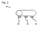
- the actuator 30 is designed as a slide switch.
- the actuator 30 has three switching states, wherein in a first switching state 31 no steam ejection is selected.
- the first switching state 31 here is the in Fig. 3 shown middle switching state.
- the actuator 30 is brought by operation of the first switching state 31 in the second switching state 32.
- the actuating element 30 is brought from the second switching state 32 back into the first switching state 31.
- the second switching state 32 here is the in Fig. 3 shown left switching state. This in Fig.
- actuator 30 is in the second switching state 32, in which the sequence of steam discharges is delivered until the actuator 30 is brought back into the first switching state 31.
- the shifting of the actuating element 30 from the first 31 to the second switching state 32, as well as the displacement of the actuating element 30 from the second 32 to the first switching state 31, is the first operating sequence.
- the actuating element further has a third switching state 33.
- a sliding movement ie by an operator, the user can bring the actuating element in the third switching state 33, wherein the actuating element when released from the third switches to the first switching state 31.
- Such an operation can also be referred to as a touch movement.
- a time-limited sequence of steam ejections which has three steam pulses, is started. After the three steam pulses, this series of steam discharges ends. However, the user can prematurely end this time-limited sequence of steam discharges by a further displacement of the actuating element 30 from the first 31 to the third switching state 33.
- the displacement of the actuating element 30 from the first 31 to the third switching state 33 is the second operating sequence in this case.
- the present invention makes it possible to provide a steam station by means of which the greatest possible pressure of a steam ejection can be achieved with simple structural and cost-effective means.
- a high rate of vaporization can be achieved thereby, whereby the work results, such as e.g. Ironing or cleaning results can be improved.
- an effective operation of the steam station and thus a reduction in energy consumption can be achieved.
- both the total amount of discharged steam can be reduced, and thus energy can be saved, as well as a higher steam discharge rate and thus an improved penetration of the steam into the ironing material can be achieved.
Description
Die vorliegende Erfindung betrifft eine Dampfstation zur Dampfbehandlung eines Bedampfungsguts mit einem Dampferzeuger zur Erzeugung eines Dampfausstoßes, und einem Betätigungselement.The present invention relates to a steam station for steaming a Bedampfungsguts with a steam generator for generating a steam ejection, and an actuating element.
Beispielsweise ist aus der deutschen Patentschrift
Weiter ist aus der US-Offenlegungsschrift
Weiter ist aus der europäischen Offenlegungsschrift
Aus dem Patent
Der Erfindung liegt die Aufgabe zugrunde, eine gegenüber dem Stand der Technik verbesserte Dampfstation bereitzustellen. Insbesondere soll eine Dampfstation bereitgestellt werden, bei der ein Dampfausstoß mit größtmöglichem Druck erreichbar ist. Weiter soll die Dampfausstoßrate eines Dampfausstoßes erhöht werden können. Des Weiteren soll eine Dampfstation bereitgestellt werden, durch die eine Verringerung des Energieverbrauchs möglich ist.The invention has for its object to provide a comparison with the prior art improved steam station. In particular, a steam station is to be provided in which a steam discharge with the highest possible pressure can be achieved. Next, the steam discharge rate of a steam ejection should be increased. Furthermore, a steam station is to be provided, through which a reduction in energy consumption is possible.
Die Bezugszeichen in sämtlichen Ansprüchen haben keine einschränkende Wirkung, sondern sollen lediglich deren Lesbarkeit verbessern.The reference numbers in all claims have no limiting effect, but are only intended to improve their readability.
Die Lösung der gestellten Aufgabe gelingt durch eine Dampfstation mit den Merkmalen des Anspruchs 1. Eine zeitlich unbegrenzte Folge von Dampfstößen ist eine Folge, die nach dem Starten vorteilhafterweise so lange läuft, bis das Betätigungselement erneut bedient wird, um die Folge von Dampfausstößen zu beenden. Unter einer zeitlich begrenzten Folge ist eine Folge zu verstehen, die nach Ablauf einer vorgegebenen Zeit endet, so dass der Dampferzeuger nach Ablauf der vorgegebenen Zeit keine Folge von Dampfausstößen mehr abgibt. Das bedeutet allerdings nicht, dass der Dampferzeuger nach Durchlaufen der zeitlich begrenzten Folge überhaupt keinen Dampf mehr abgibt. Natürlich kann nach Durchlaufen der zeitlich begrenzten Folge, also nach Ablauf der vorgegebenen Zeit, immer noch ein konstanter Dampfausstoß abgegeben werden. Vorteilhafterweise kann durch eine zeitlich begrenzte Folge von Dampfausstößen die Bedienung des Dampferzeugers vereinfacht werden, da der Benutzer während der Benutzung, z.B. während eines Bügelvorgangs, die zeitlich begrenze Folge durch Bedienen des Betätigungselements starten kann, ohne diese durch ein erneutes Bedienen wieder beenden zu müssen, da diese vorteilhafterweise nach Ablauf der vorgegebenen Zeit endet. Somit kann sich der Benutzer besser auf den eigentlichen Arbeitsvorgang, z.B. einen Bügel- oder Reinigungsvorgang konzentrieren.The solution of the problem is achieved by a steam station with the features of claim 1. A time-unlimited sequence of steam surges is a consequence that advantageously runs after starting so long until the actuator again is operated to end the series of steam discharges. A time-limited sequence is understood to mean a sequence which ends after a predetermined time has elapsed, so that the steam generator no longer gives off a series of steam discharges after the predetermined time has elapsed. However, this does not mean that the steam generator does not give off any steam after passing through the time-limited sequence. Of course, after passing through the temporally limited sequence, that is after the expiration of the predetermined time, still a constant output of steam can be delivered. Advantageously, the operation of the steam generator can be simplified by a time-limited sequence of steam discharges, since the user during use, eg during a ironing operation, the time-limited sequence can start by operating the actuator without having to end this by re-operating again since this ends advantageously after the expiration of the predetermined time. Thus, the user can concentrate better on the actual work process, such as an ironing or cleaning process.
Unter einer Dampfstation ist ein System zur Bereitstellung und/oder zur Abgabe von Dampf zu verstehen, um ein Bedampfungsgut mit Dampf behandeln zu können. Hierzu kann der Dampferzeuger zumindest einen Dampfausstoß erzeugen. Die Dampfstation kann z.B. zur Pflege von Bekleidung eingesetzt werden, und hierzu z.B. als Bügelgerät, Bügelstation, Dampfglätter, sogenannte Steambrush oder Dampfbürste ausgeführt sein. Eine erfindungsgemäße Dampfstation kann auch zu Reinigungszwecken eingesetzt werden, und z.B. als Dampfreiniger ausgeführt sein. Unter einer Folge von Dampfausstößen ist eine Folge zu verstehen, in der sich Phasen mit höheren Dampfausstoßraten und Phasen mit niedrigeren oder gar keinen Dampfausstoßraten abwechseln. Die Phasen mit einer höheren Dampfausstoßrate werden als Dampfausstöße der Folge von Dampfausstößen betrachtet. Eine Folge von Dampfausstößen kann auch als Folge von Dampfpulsen bezeichnet werden. Unter einer Dampfausstoßrate ist die Dampfmenge eines Dampfausstoßes zu verstehen, die in einer bestimmten Zeiteinheit abgegeben wird. Üblicherweise wird die Dampfausstoßrate in Gramm pro Minute (g/min) gemessen. Durch das Starten und/oder Beenden der Folge von Dampfausstößen wird der Ablauf der Folge, also der Wechsel von Phasen mit höherer und Phasen mit niedrigerer oder gar keiner Dampfausstoßrate, sowie die Dauer der Phasen, nicht beeinflusst. Dass die Folge von Dampfausstößen startbar und/oder beendbar ist, während die Dampfstation zur Bearbeitung des Bedampfungsguts gehandhabt wird heißt, dass ein Benutzer die Handhabung nicht unterbrechen muss, um die Folge zu starten und/oder zu beenden. Unter Handhabung ist hierbei die Tätigkeit eines Benutzers zu verstehen, die der Benutzer durchführt, um das Bedampfungsgut zu bearbeiten. Dies kann z.B. das Führen eines Bügeleisens oder eines Reinigungsgeräts sein.A steam station is to be understood as a system for providing and / or delivering steam in order to be able to treat a material to be steamed. For this purpose, the steam generator can generate at least one steam output. The steam station can be used, for example, for the care of clothing, and be designed for this purpose, for example, as ironing, ironing station, steam straightener, so-called steam brush or steam brush. A steam station according to the invention can also be used for cleaning purposes, and be designed, for example, as a steam cleaner. A series of steam ejections is a sequence in which phases alternate with higher steam ejection rates and phases with lower or no steam ejection rates. The phases with a higher steam discharge rate are considered as steam discharges from the series of steam discharges. A series of steam bursts may also be referred to as a result of steam pulses. A steam discharge rate is the amount of steam that is released in a given time unit. Usually, the steam discharge rate is measured in grams per minute (g / min). By starting and / or stopping the sequence of steam discharges, the sequence of the sequence, ie the change of phases with higher and phases with lower or no steam discharge rate, as well as the duration of the phases, is not affected. That the sequence of steam discharges is startable and / or terminable, while the steam station for processing the Bedampfungsguts means that a user does not have to interrupt the handling in order to start and / or end the sequence. By handling is here to be understood the activity of a user that the user carries out in order to process the material to be steamed. This can be, for example, the guiding of an iron or a cleaning device.
Es ist ein erreichbarer Vorteil der Erfindung, dass durch die Folge von Dampfausstößen die Dampfausstoßrate der Dampfausstöße erhöht werden kann. Denn bei einer Folge von Dampfstößen kann die Zeitdauer jedes Dampfausstoßes vorteilhafterweise so kurz sein, dass ein Druckabfall während eines Dampfausstoßes minimiert werden kann, und somit während eines Dampfausstoßes eine höhere Dampfmenge transportiert werden kann. Vorteilhafterweise kann der während eines Dampfausstoßes abgefallene Dampfdruck zwischen den Dampfausstößen wieder regeneriert werden, also auf den Anfangsdruckwert erhöht werden. Der Änfangsdruckwert ist der Wert des Dampfdruckes, der zu Beginn eines Dampfausstoßes, also vor Beginn eines Druckabfalls herrscht. Üblicherweise ist der Anfangsdruckwert der höchste Dampfdruck eines Dampfausstoßes. Durch die Regeneration des Dampfdruckes zwischen den Dampfausstößen kann für jeden Dampfausstoß einer Folge von Dampfausstößen der größtmögliche Druck erreichbar sein. Vorteilhafterweise kann dies einen kontinuierlichen Druckabfall während des Ablaufs der Folge verhindern. Vorteilhafterweise kann hierdurch erreicht werden, dass jeder Dampfausstoß einer Folge den gleichen zeitlichen Dampfdruckverlauf, und somit eine gleich hohe Dampfausstoßrate aufweist.It is an achievable advantage of the invention that the steam ejection rate of the steam ejections can be increased by the sequence of steam ejections. For in a series of steam bursts, the duration of each steam ejection may advantageously be so short that a pressure drop during steam ejection can be minimized, and thus a higher amount of steam can be transported during steam ejection. Advantageously, the vapor pressure dropped off during a steam discharge between the steam discharges can be regenerated again, that is, increased to the initial pressure value. The initial pressure value is the value of the vapor pressure prevailing at the beginning of a steam discharge, ie before the beginning of a pressure drop. Usually, the initial pressure value is the highest vapor pressure of a vapor ejection. By regenerating the vapor pressure between the steam ejections, the greatest possible pressure can be achieved for each steam ejection of a succession of steam ejections. Advantageously, this can prevent a continuous pressure drop during the course of the sequence. Advantageously, it can thereby be achieved that each steam ejection of a sequence has the same temporal vapor pressure profile, and thus an equally high steam ejection rate.
Weiter kann durch die Erfindung eine Verbesserung der Arbeitsergebnisse erreicht werden, da bei der Folge von Dampfausstößen eine höhere Dampfausstoßrate der Dampfausstöße erreichbar ist. Hierdurch kann der Dampf z.B. besser in das Bügelgut eindringen, oder Schmutz besser von einer Oberfläche lösen. Weiter kann durch die Folge von Dampfausstößen ein verbessertes Gleiten eines Bügeleisens auf dem Bügelgut aufgrund des konstant hohen Dampfdrucks der Dampfausstöße der Folge erreichbar sein.Further, an improvement of the working results can be achieved by the invention, since in the sequence of steam ejections, a higher steam discharge rate of the steam ejections can be achieved. As a result, the vapor may e.g. better penetrate the material to be ironed, or remove dirt from a surface better. Furthermore, due to the succession of steam discharges, an improved sliding of an iron on the ironing material can be achieved due to the constantly high vapor pressure of the steam ejections of the sequence.
Es ist ein erreichbarer Vorteil des erfindungsgemäßen Betätigungselements, dass der Benutzer jederzeit während der Handhabung zur Bearbeitung des Bedampfungsguts, z.B. während eines Bügel- oder Reinigungsvorgangs auswählen kann, ob er die Dampfstation mit oder ohne Abgabe einer Folge von Dampfausstößen betreiben möchte.It is an achievable advantage of the actuator according to the invention that the user can select at any time during handling for processing the Bedampfungsguts, eg during ironing or cleaning process, whether he wants to operate the steam station with or without dispensing a series of steam discharges.
Typischerweise beginnt ein Bügel- oder Reinigungsvorgang mit dem Anfassen eines Teils der Dampfstation, z.B. eines Bügeleisens oder eines Reinigungsgeräts, und endet mit dem Loslassen desselben. Vorteilhafterweise kann dadurch Energie eingespart werden, da die Dampfstation auch ohne Abgabe einer Folge von Dampfausstößen betrieben werden kann.Typically, an ironing or cleaning operation begins by engaging a portion of the steam station, e.g. an iron or a cleaning device, and ends with the release of the same. Advantageously, this energy can be saved, since the steam station can be operated without dispensing a series of steam discharges.
Es ist ein weiterer erreichbarer Vorteil, dass durch die Erzeugung einer Folge von Dampfstößen ein effektiver Betrieb der Dampfstation und somit eine Verringerung des Energieverbrauchs der Dampfstation erreichbar sein kann. Durch die Abgabe einer Folge von Dampfausstößen kann nämlich die abgegebene Dampfmenge reduziert werden, da vorteilhafterweise in den Phasen mit niedrigerer oder gar keiner Dampfausstoßrate weniger Dampf abgegeben werden kann.It is another achievable advantage that by generating a train of steam bursts, effective operation of the steam station and thus a reduction in steam station energy consumption can be achieved. In fact, by delivering a series of steam discharges, the amount of steam delivered can be reduced because advantageously less steam can be dispensed in the phases of lower or no steam discharge rate.
Vorteilhafterweise kann die Folge von Dampfausstößen durch den Benutzer über eine Bedienung des Betätigungselements gestartet und/oder beendet werden, so dass der Benutzer die Folge nach Bedarf starten und/oder beenden kann. Weiter ist vorteilhafterweise erreichbar, dass der Benutzer den Ablauf der Folge nicht kontrollieren muss, und sich so besser auf den Arbeitsvorgang, z.B. einen Bügel- oder Reinigungsvorgang konzentrieren kann.Advantageously, the sequence of steam discharges can be started and / or terminated by the user via an operation of the actuating element, so that the user can start and / or terminate the sequence as required. Furthermore, it is advantageously achievable that the user does not have to control the sequence of the sequence, and thus is better able to concentrate on the working process, e.g. can concentrate a ironing or cleaning process.
Vorteilhafte Aus- und Weiterbildungen, welche einzeln oder in Kombination miteinander eingesetzt werden können, sind Gegenstand der abhängigen Ansprüche.Advantageous embodiments and developments, which can be used individually or in combination with each other, are the subject of the dependent claims.
Besonders vorzugsweise ist die Zeitdauer eines Dampfausstoßes der Folge von Dampfausstößen so kurz, dass der Druckabfall während des Dampfausstoßes 15 %, besonders vorzugsweise 10 %, besonders vorzugsweise 5 % nicht übersteigt. In einer besonders bevorzugten Folge von Dampfausstößen beträgt die Zeitdauer zwischen aufeinander folgenden Dampfausstößen zumindest 0,5 Sekunden, besonders vorzugsweise zumindest 1,0 Sekunden. Besonders vorzugsweise weist jeder Dampfausstoß eine Zeitdauer von maximal 1,0 Sekunden, besonders vorzugsweise von maximal 0,5 Sekunden auf.Particularly preferably, the duration of steam ejection of the series of steam ejections is so short that the pressure drop during steam ejection does not exceed 15%, more preferably 10%, most preferably 5%. In a particularly preferred sequence of steam ejections, the time period between successive steam ejections is at least 0.5 seconds, more preferably at least 1.0 seconds. Particularly preferably, each steam ejection has a maximum duration of 1.0 second, particularly preferably of 0.5 second maximum.
In einer besonders bevorzugten Ausführungsform wird das Betätigungselement durch eine Tastbewegung bedient, wobei das Betätigungselement durch die Tastbewegung von einem ersten Schaltzustand in einen zweiten Schaltzustand, und nach Beendigung der Tastbewegung von dem zweiten in den ersten Schaltzustand bringbar ist. Besonders vorzugsweise weist das Betätigungselement ein elastisches Element auf, durch das nach Beendigen der Tastbewegung das Betätigungselement von dem zweiten in den ersten Schaltzustand bringbar ist. Die Tastbewegung kann z.B. ein Antippen, Drücken oder Ziehen und anschließendes Loslassen des Betätigungselements sein. Vorteilhafterweise kann durch die Tastbewegung die Folge von Dampfausstößen gestartet und/oder beendet werden. So kann die Folge von Dampfausstößen z.B. durch eine erste Tastbewegung gestartet, und durch eine auf die erste folgende zweite Tastbewegung beendet werden. Vorteilhafterweise ist keine zusätzliche Interaktion des Benutzers mit dem Betätigungselement erforderlich, um die Folge von Dampfausstößen ablaufen zu lassen. Dies kann eine Erleichterung des Bügelvorgangs bedeuten, da der Benutzer während des Bügelvorgangs die Folge von Dampfausstößen durch eine einfache Bedienung des Betätigungselements starten kann, und sich während der Abgabe der Dampfausstöße auf den eigentlichen Bügelvorgang konzentrieren kann. Vorteilhafterweise kann der Benutzer die Folge von Dampfausstößen jederzeit durch eine erneute Bedienung des Betätigungselements wieder beenden.In a particularly preferred embodiment, the actuating element is operated by a tactile movement, wherein the actuating element can be brought by the tactile movement of a first switching state in a second switching state, and after completion of the tactile movement of the second in the first switching state. Particularly preferably, the actuating element has an elastic element, by means of which the actuating element can be brought from the second to the first switching state after the end of the scanning movement. The tactile movement may e.g. be a tap, press or pull and then release the actuator. Advantageously, the sequence of steam discharges can be started and / or terminated by the touch movement. Thus, the series of steam discharges, e.g. started by a first touch movement, and terminated by a first following the second touch movement. Advantageously, no additional interaction of the user with the actuator is required to run the sequence of steam discharges. This may facilitate the ironing operation, since during the ironing operation, the user can start the series of steam discharges by a simple operation of the operating member, and concentrate on the actual ironing operation during the delivery of the steam discharges. Advantageously, the user can end the sequence of steam discharges at any time by re-operation of the actuating element.
In einer weiteren besonders bevorzugten Ausführung wird das Betätigungselement durch Bedienen von einem ersten Schaltzustand in einen zweiten Schaltzustand gebracht, um die Folge von Dampfausstößen zu starten, und von dem zweiten in den ersten Schaltzustand gebracht, um die Folge von Dampfausstößen zu beenden. Hierbei kann das Betätigungselement gedrückt oder gezogen werden, um von dem ersten in den zweiten Zustand gebracht zu werden, und losgelassen werden, um von dem zweiten in den ersten Zustand gebracht zu werden. Hierbei ist der Benutzer zwar mit dem Betätigungselement während der Abgabe der Folge von Dampfausstößen in Kontakt, allerdings beeinflusst der Benutzer nicht den Ablauf der Phasen der Folge durch seine Interaktion mit dem Betätigungselement. Dies kann vorteilhafterweise eine Vereinfachung der Bedienung zur Steuerung der Folge von Dampfausstößen ermöglichen, da die Dampfausstöße nur in der Zeit abgegeben werden, in der der Benutzer mit dem Betätigungselement interagiert, dieses z.B. gedrückt oder gezogen hält. Außerdem kann eine Verbesserung der Bügelergebnisse ermöglicht werden, da der Benutzer bei ungleichmäßiger Faltenbildung des Bügelguts die Abgabe der Dampfausstöße nicht während des gesamten Bügelvorgangs aktivieren muss, sondern gezielt ein- und ausschalten kann.In another particularly preferred embodiment, the actuator is brought by operation from a first switching state to a second switching state to start the series of steam discharges, and brought from the second to the first switching state to terminate the series of steam discharges. Here, the actuator may be pushed or pulled to be brought from the first to the second state, and released to be brought from the second to the first state. In this case, while the user is in contact with the actuator during delivery of the train of vapor ejections, the user does not affect the course of the phases of the sequence through its interaction with the actuator. This may advantageously allow simplification of the operation for controlling the sequence of steam discharges, since the steam discharges are delivered only in the time in which the user interacts with the actuating element, for example by holding or pulling it. In addition, can an improvement of the ironing results are possible because the user with uneven wrinkling of the ironing the delivery of the steam ejections does not have to activate during the entire ironing process, but can selectively switch on and off.
In einer weiteren besonders bevorzugten Ausführung wird das Betätigungselement durch eine Tastbewegung in den ersten und/oder zweiten Zustand gebracht, wobei das Betätigungselement durch eine Einrastvorrichtung in der jeweiligen Position verbleibt, und nicht in den vorherigen Zustand zurück kehrt. Besonders vorzugsweise wird ein Teil des Betätigungselements bei der Bedienung des Betätigungselements verschoben, um den Schaltzustand des Betätigungselements zwischen dem ersten und zweiten Schaltzustand zu wechseln. Ein solches Betätigungselement kann z.B. als Schiebschalter ausgeführt sein. Besonders vorzugsweise erfolgt die Bedienung des Betätigungselements gegen eine Kraft, z.B. eine Federkraft eines elastisch verformbaren Elements, wodurch eine versehentliche Bedienung des Betätigungselements vermieden werden kann.In a further particularly preferred embodiment, the actuating element is brought by a tactile movement in the first and / or second state, wherein the actuating element by a latching device in the respective position remains, and does not return to the previous state. Particularly preferably, a part of the actuating element is displaced during the operation of the actuating element in order to change the switching state of the actuating element between the first and second switching state. Such an actuator may e.g. be designed as a slide switch. Most preferably, the operation of the actuator is against a force, e.g. a spring force of an elastically deformable element, whereby accidental operation of the actuating element can be avoided.
Die Folge von Dampfausstößen ist durch eine erste Bedienfolge des Betätigungselements startbar und/oder beendbar. Unter einer Bedienfolge des Betätigungselements sind durch eine Bedienung hervorgerufene, zeitlich aufeinander folgende, voneinander abweichende Zustände des Betätigungselements zu verstehen. Besonders vorzugsweise besteht die erste Bedienfolge aus einer einzelnen Tastbewegung. Das bedeutet, dass das Betätigungselement durch eine Tastbewegung bedient wird, um die Folge von Dampfausstößen zu starten und/oder zu beenden. Diese Tastbewegung kann mit einem "Einfach-Klick" bei der Bedienung einer Computermaus verglichen werden.The sequence of steam discharges can be started and / or terminated by a first operating sequence of the actuating element. Under an operating sequence of the actuating element are caused by an operation to be understood, temporally successive, divergent states of the actuating element. Particularly preferably, the first operating sequence consists of a single touch movement. This means that the actuating element is operated by a tactile movement in order to start and / or end the series of steam ejections. This tactile movement can be compared with a "single click" when operating a computer mouse.
Besonders vorzugsweise ist das Betätigungselement durch Bedienung in einen dritten Schaltzustand bringbar, um die zeitlich begrenzte Folge von Dampfausstößen zu starten und/oder zu beenden. Vorteilhafterweise kann die zeitlich begrenzte Folge auch vor Ablauf der vorgegebenen Zeit durch Bedienen des Betätigungselements beendet werden. In einer besonders bevorzugten Ausführung der Erfindung weist die zeitlich begrenzte Folge eine festgelegte Anzahl an Dampfstößen auf. Mit anderen Worten, die vorgegebene Zeit der zeitlich begrenzten Folge ist in dieser Ausführung so bemessen, dass nach Ablauf dieser Zeit eine festgelegte Anzahl an Dampfstößen abgegeben wurde. Durch Bedienen des Betätigungselements ist also eine Folge von Dampfausstößen mit einer begrenzten Anzahl an Dampfausstößen startbar und/oder beendbar. Besonders vorzugsweise umfasst die zeitlich begrenzte Folge fünf, besonders vorzugsweise drei Dampfstöße.Particularly preferably, the actuating element can be brought by operation in a third switching state to start the temporally limited sequence of steam ejections and / or to end. Advantageously, the time-limited sequence can also be terminated before the expiry of the predetermined time by operating the actuating element. In a particularly preferred embodiment of the invention, the time-limited sequence has a fixed number of steam bursts. In other words, the predetermined time of the time-limited sequence is dimensioned in this embodiment so that after this time a fixed number of steam bursts was delivered. By Operating the actuating element is thus a series of steam discharges with a limited number of steam discharges can be started and / or terminated. Particularly preferably, the time-limited sequence comprises five, particularly preferably three bursts of steam.
Der Benutzer kann allerdings auch, falls er z.B. das Betätigungselement fälschlicherweise bedient hat, oder die Dampfausstöße nicht mehr benötigt, durch erneutes Bedienen des Betätigungselements die zeitlich begrenzte Folge von Dampfausstößen vorzeitig beenden.However, the user may also, if he has operated the actuator incorrectly, or no longer requires the steam ejections, terminate the time-limited sequence of steam ejections prematurely by re-operating the actuator.
Erfindungsgemäß ist vorzugsweise vorgesehen, dass eine zeitlich begrenzte Folge von Dampfausstößen durch eine zweite Bedienfolge des Betätigungselements startbar und/oder beendbar ist. Unter einer Bedienfolge des Betätigungselements sind durch eine Bedienung hervorgerufene, zeitlich aufeinander folgende, voneinander abweichende Zustände des Betätigungselements zu verstehen. Besonders vorzugsweise besteht die zweite Bedienfolge aus zwei Tastbewegungen des Betätigungselements, wobei der zeitliche Abstand zwischen den Tastbewegungen eine festgelegte Zeitdauer nicht überschreitet. Das bedeutet, dass das Betätigungselement durch eine zweimalige Tastbewegung bedient wird, um die zeitlich begrenzte Folge von Dampfausstößen zu starten und/oder zu beenden. Die Zeitdauer zwischen den beiden Tastbewegungen darf hierbei eine festgelegte Zeitdauer nicht überschreiten. Diese zweimalige Tastbewegung kann mit einem "Doppel-Klick" bei der Bedienung einer Computermaus verglichen werden. Der zeitliche Abstand zwischen den einzelnen Tastbewegungen der zweiten Bedienfolge beträgt besonders vorzugsweise maximal nur eine Sekunde, besonders vorzugsweise maximal nur eine halbe Sekunde. Durch die zweimalige Tastbewegung der zweiten Bedienfolge kann eine einfache Bedienung ermöglicht werden, da dem Benutzer eine solche Folge bereits aus der Bedienung eines Computers mit einer Maus bekannt sein kann. Vorteilhafterweise ist durch die erste und/oder die zweite Bedienfolge erreichbar, dass eine zeitlich unbegrenzte und/oder zeitlich begrenzte Folge von Dampfausstößen durch ein einziges Element, nämlich durch das Betätigungselement gesteuert werden kann. Hierdurch können Komponenten eingespart werden, was zu einerAccording to the invention, it is preferably provided that a time-limited sequence of steam discharges can be started and / or terminated by a second operating sequence of the actuating element. Under an operating sequence of the actuating element are caused by an operation to be understood, temporally successive, divergent states of the actuating element. Particularly preferably, the second operating sequence of two scanning movements of the actuating element, wherein the time interval between the touch movements does not exceed a predetermined period of time. This means that the actuating element is operated by a double touch movement in order to start and / or end the time-limited sequence of steam discharges. The time between the two tactile movements may not exceed a fixed period of time. This two-time tactile movement can be compared with a "double-click" when operating a computer mouse. The time interval between the individual scanning movements of the second operating sequence is particularly preferably a maximum of only one second, particularly preferably a maximum of only half a second. The two-time touch movement of the second sequence of operation, a simple operation can be made possible because the user of such a sequence can already be known from the operation of a computer with a mouse. Advantageously, can be achieved by the first and / or the second sequence of operation that a time-unlimited and / or temporally limited sequence of steam discharges can be controlled by a single element, namely by the actuator. As a result, components can be saved, resulting in a
kostengünstigeren Dampfstation führen kann. Weiter kann eine vereinfachte Bedienung der Dampfstation über ein das Betätigungselement ermöglicht werden.lower cost steam station can lead. Furthermore, a simplified operation of the steam station via an actuating element can be made possible.
Gemäß der Erfindung weist die Dampfstation eine Steuereinheit zum Steuern des Dampfausstoßes auf. In einer Ausführung der Erfindung ist das Betätigungselement als Schalter ausgeführt. In einer besonders bevorzugten Ausführungsform ist das Betätigungselement als Tastschalter ausgeführt. Der Tastschalter kann z.B. bei einer Bedienung gedrückt oder gezogen werden. Der Tastschalter kann auch als Sensorschalter ausgeführt sein, der bei einer Bedienung berührt wird. Dieses Berühren kann ebenfalls als Tastbewegung betrachtet werden. Besonders vorzugsweise ist der Tastschalter durch Bedienung in eine erste und zweite Schaltposition bringbar. Vorteilhafterweise ist die erste und/oder zweite Bedienfolge an einem als Tastschalter ausgeführten Betätigungselement leicht durchführbar, wobei der Tastschalter durch einmalige bzw. durch zweimalige Bedienung kurz hintereinander bedient werden kann. Vorteilhafterweise ist ein solcher Tastschalter auch während eines Arbeitsvorgangs, z.B. während eines Bügel- oder Reinigungsvorgangs leicht bedienbar.According to the invention, the steam station has a control unit for controlling the steam output. In one embodiment of the invention, the actuating element is designed as a switch. In a particularly preferred embodiment, the actuating element is designed as a push-button. The key switch may e.g. be pressed or pulled during an operation. The key switch can also be designed as a sensor switch, which is touched during operation. This touching can also be considered as a tactile movement. Particularly preferably, the key switch can be brought by operation in a first and second switching position. Advantageously, the first and / or second sequence of operations on an operating element designed as a push-button switch is easy to carry out, wherein the push-button switch can be operated by one-time or by two operations briefly in quick succession. Advantageously, such a key switch is also during a work operation, e.g. easy to operate during ironing or cleaning.
In einer weiteren besonders bevorzugten Ausführungsform ist das Betätigungselement als Schiebschalter ausgeführt. Der Schiebschalter kann z.B. zwei Schaltzustände, einen ersten und einen zweiten Schaltzustand aufweisen, wobei z.B. durch den ersten Schaltzustand kein Dampfausstoß oder ein konstanter Dampfausstoß gewählt, und durch den zweiten Schaltzustand die Abgabe einer Folge von Dampfausstößen gewählt sein kann. Der durch den zweiten Schaltzustand gewählte Betrieb der Dampfstation kann auch als Dampfpulsbetrieb bezeichnet werden. Besonders vorzugsweise weist das als Schiebschalter ausgeführte Betätigungselement einen dritten Schaltzustand auf, durch den eine zeitlich begrenzten Folge von Dampfausstößen gestartet und/oder beendet werden kann. Besonders vorzugsweise ist die dritte Stellung eine Taststellung. Das bedeutet, dass das Betätigungselement nach einer Bedienung wieder in die vorherige Stellung, z.B. in die erste oder zweite Stellung wechselt. Besonders vorzugsweise weist das als Schiebschalter ausgeführte Betätigungselement alle drei Schaltzustände, erster, zweiter sowie dritter Schaltzustand, auf.In a further particularly preferred embodiment, the actuating element is designed as a slide switch. The slide switch may e.g. two switching states, a first and a second switching state, wherein e.g. no steam output or a constant steam output is selected by the first switching state, and the delivery of a series of steam discharges can be selected by the second switching state. The operation of the steam station selected by the second switching state may also be referred to as steam pulse operation. Particularly preferably, the actuating element designed as a slide switch has a third switching state, by means of which a time-limited sequence of steam discharges can be started and / or terminated. Particularly preferably, the third position is a tactile position. This means that the actuator returns to the previous position after operation, e.g. changes to the first or second position. Particularly preferably, the operating element designed as a slide switch has all three switching states, first, second and third switching state.
In einer bevorzugten Ausführung ist die Steuereinheit an dem Dampferzeuger angeordnet. Besonders vorzugsweise ist die Steuereinheit mit dem Betätigungselement verbunden. Besonders vorzugsweise ist die Steuereinheit über eine Leitung mit dem Betätigungselement verbunden.In a preferred embodiment, the control unit is arranged on the steam generator. Particularly preferably, the control unit is connected to the actuating element. Particularly preferably, the control unit is connected via a line to the actuating element.
In einer weiteren bevorzugten Ausführung weist die Dampfstation ein Ventil auf, durch das die Folge von Dampfausstößen erzeugbar ist. Besonders vorzugsweise ist das Ventil an dem Dampferzeuger angeordnet. Besonders vorzugsweise ist das Ventil mit der Leitung eines Bügeleisens verbindbar. Vorteilhafterweise kann durch Öffnen und Schließen des Ventils Dampfdruck kontrolliert durch den Schlauch zu dem Bügeleisen geführt werden, um so einen Dampfausstoß und/oder eine Folge von Dampfausstößen erzeugen zu können. Besonders vorzugsweise ist das Ventil in eine Stellung zwischen der geöffneten und der geschlossenen Stellung bringbar, so dass durch das Ventil auch die austretende Dampfmenge gesteuert werden kann. Vorteilhafterweise ist durch das Ventil jede beliebige Folge von Dampfausstößen erzeugbar, bei der sich Phasen mit höheren Dampfausstoßraten und Phasen mit niedrigeren Dampfausstoßraten abwechseln. Besonders vorzugsweise weist der Dampferzeuger einen Dampfkessel zur Erzeugung eines Dampfdruckes auf, der über das Ventil mit dem Schlauch eines Bügeleisens verbindbar ist. Besonders vorzugsweise ist das Ventil über die Steuereinheit steuerbar. Hierdurch ist erreichbar, dass eine beliebige Folge von Dampfausstößen erzeugt werden kann. Besonders vorzugsweise ist das Ventil als Elektroventil ausgeführt.In a further preferred embodiment, the steam station has a valve, by means of which the sequence of steam discharges can be generated. Particularly preferably, the valve is arranged on the steam generator. Particularly preferably, the valve is connectable to the line of an iron. Advantageously, by opening and closing the valve, vapor pressure can be controlled through the hose to the iron, so as to be able to produce a steam output and / or a series of steam discharges. Particularly preferably, the valve can be brought into a position between the open and the closed position, so that through the valve and the exiting amount of steam can be controlled. Advantageously, the valve can produce any desired series of steam discharges, in which phases alternate with higher steam discharge rates and phases with lower steam discharge rates. Particularly preferably, the steam generator to a steam boiler for generating a vapor pressure, which is connectable via the valve with the hose of an iron. Particularly preferably, the valve is controllable via the control unit. This makes it achievable that any sequence of steam discharges can be generated. Particularly preferably, the valve is designed as an electrovalve.
Die Erfindung weiterbildend ist vorzugsweise vorgesehen, dass die Dampfstation ein Bügeleisen aufweist, an dem das Betätigungselement angeordnet ist. Besonders vorzugsweise ist die Dampfstation als Bügelstation ausgeführt. Besonders vorzugsweise ist das Bügeleisen über eine Leitung, besonders vorzugsweise über einen Schlauch an den Dampferzeuger angeschlossen, um das Bügeleisen mit Dampf zum Bügeln versorgen zu können. Hierdurch ist erreichbar, dass der Benutzer während des Bügelvorgangs die Folge von Dampfausstößen einfach starten und/oder beenden kann, so dass eine verbesserte Bedienung der Dampfstation erreichbar ist. Typischerweise beginnt ein Bügelvorgang mit dem Anfassen des Bügeleisens, und endet mit dem Loslassen des Bügeleisens. Vorteilhafterweise ist durch Bedienen des Betätigungselements eine Folge von Dampfausstößen während eines Bügelvorgangs bei bestimmungsgemäßen Betrieb der Dampfstation startbar und/oder beendbar. Natürlich kann die Folge von Dampfausstößen auch vor oder nach einem Bügelvorgang startbar und/oder beendbar sein. Vorteilhafterweise startet die Folge von Dampfausstößen nicht mit dem Anfassen des Bügeleisens und wird nicht mit dem Loslassen des Bügeleisens beendet, so dass dem Benutzer ermöglicht werden kann, während des Bügelns von Bügelgut bei Bedarf, z.B. um stark verknitterte Stellen des Bügelguts zu glätten, die Folge von Dampfausstößen zu starten und/oder zu beenden.The invention further development is preferably provided that the steam station comprises an iron on which the actuating element is arranged. Particularly preferably, the steam station is designed as an ironing station. Particularly preferably, the iron is connected via a line, particularly preferably via a hose to the steam generator in order to supply the iron with steam for ironing can. This makes it possible for the user to easily start and / or terminate the sequence of steam discharges during the ironing process, so that an improved operation of the steam station can be achieved. Typically, ironing begins with the touch of the iron, and ends with the release of the iron. Advantageously, by operating the actuating element, a series of steam discharges can be started and / or terminated during a pressing operation during normal operation of the steam station. Of course, the sequence of steam discharges can also be started and / or terminated before or after an ironing process. Advantageously, the sequence of steam discharges does not start with the touch of the iron and is not terminated with the release of the iron, so that the user can be enabled during the ironing of Ironing material as needed, eg to smooth out heavily wrinkled areas of the ironing stock, to start and / or end the sequence of steam ejections.
Besonders vorzugsweise ist das Betätigungselement durch Leitungen mit dem Dampferzeuger verbindbar. Besonders vorzugsweise ist das Bestätigungselement durch Leitungen mit der Steuereinheit verbindbar. Durch die Leitungen ist eine Übertragung des Schaltzustands des Betätigungselements an den Dampferzeuger und/oder die Steuereinheit erreichbar.Particularly preferably, the actuating element can be connected by lines to the steam generator. Particularly preferably, the confirmation element can be connected by lines to the control unit. Through the lines, a transmission of the switching state of the actuating element to the steam generator and / or the control unit can be achieved.
In einer Ausführung der Erfindung weist die Dampfstation ein Einstellelement zur Einstellung des Ablaufs der Folge von Dampfausstößen auf. Durch das Einstellelement kann der Benutzer vor Beginn und/oder während eines Arbeitsvorgangs, z.B. während eines Bügel- oder Reinigungsvorgangs den Ablauf der Folge von Dampfausstößen einstellen, um diese z.B. auf das Bügelgut oder eine zu reinigende Fläche anpassen zu können. Besonders vorzugsweise ist durch das Einstellelement die Frequenz der Folge von Dampfausstößen einstellbar. Hierbei ist durch das Einstellelement die Periodendauer der Folge von Dampfausstößen veränderbar, wobei die Periodendauer dem zeitlichen Abstand zwischen dem Beginn von zwei aufeinanderfolgenden Dampfausstößen entspricht. Durch die Einstellung der Frequenz kann gesteuert werden, welche Dampfmenge verbraucht wird, so dass eine Reduzierung des Energieverbrauchs ermöglicht werden kann. Ein besonders bevorzugtes Einstellelement ist als Drehschalter ausgebildet. Besonders vorzugsweise ist die Frequenz der Folge von Dampfausstößen über den Drehgrad des Drehschalters einstellbar.In one embodiment of the invention, the steam station has an adjusting element for setting the sequence of the sequence of steam discharges. The adjustment element allows the user to start and / or during a work operation, e.g. during an ironing or cleaning operation, adjust the sequence of the sequence of steam discharges to make them e.g. to be able to adapt to the ironing or a surface to be cleaned. Particularly preferably, the frequency of the sequence of steam ejections can be set by the adjusting element. Here, the period of the sequence of steam ejections is variable by the setting element, wherein the period corresponds to the time interval between the beginning of two successive steam ejections. By adjusting the frequency, it is possible to control which amount of steam is consumed, so that a reduction of the energy consumption can be made possible. A particularly preferred adjustment is designed as a rotary switch. Particularly preferably, the frequency of the sequence of steam discharges via the rotation of the rotary switch is adjustable.
In einer besonders bevorzugten Ausführung der Erfindung ist durch das Einstellelement die Zeitdauer zwischen aufeinander folgenden Dampfausstößen, also die Zeitdauer einer Phase mit niedriger oder gar keiner Dampfausstoßrate, einstellbar. Besonders vorzugsweise ist hierbei die Zeitdauer der einzelnen Dampfausstöße der Folge von Dampfausstößen konstant. Die Erfindung umfasst allerdings auch Ausführungen, in denen durch das Einstellelement die Zeitdauer eines Dampfausstoßes und die Zeitdauer zwischen aufeinander folgenden Dampfausstößen durch das Einstellelement in einem festgelegten Verhältnis veränderbar sind. Besonders vorzugsweise beträgt hierbei das Verhältnis zwischen der Zeitdauer eines Dampfausstoßes und der Zeitdauer zwischen aufeinanderfolgenden Dampfausstößen 0,5.In a particularly preferred embodiment of the invention, the period between successive steam ejections, so the duration of a phase with low or no steam discharge rate, adjustable by the adjustment. Particularly preferably, the duration of the individual steam ejections of the sequence of steam ejections is constant. However, the invention also includes embodiments in which by the adjusting the time duration of a steam ejection and the time duration between successive steam ejections are changed by the adjusting element in a fixed ratio. Particularly preferably, the ratio between the duration of a steam ejection and the time duration between successive steam ejections is 0.5.
Erfindungsgemäß ist vorzugsweise vorgesehen, dass die Dampfstation einen Dampfschalter zum Starten und/oder Beenden eines kontinuierlichen Dampfausstoßes aufweist. Durch Bedienung des Dampfschalters kann der Benutzer die Abgabe eines kontinuierlichen Dampfausstoßes starten und/oder beenden, wobei für die Bedienung des Dampfschalters die gleichen Möglichkeiten wie für die Bedienung des Betätigungselements bestehen. Besonders vorzugsweise ist durch den Dampfschalter die Dampfausstoßrate eines kontinuierlichen Dampfausstoßes auswählbar. Besonders vorzugsweise ist der Dampfschalter durch Bedienung von einer Nullstellung, in der kein kontinuierlicher Dampfausstoß abgegeben wird, in zumindest eine von der Nullstellung abweichende Stellung bringbar. Durch die von der Nullstellung abweichende Stellung kann die Dampfausstoßrate des kontinuierlichen Dampfausstoßes ausgewählt werden. Besonders vorzugsweise ist ein solcher Dampfschalter als Drehschalter ausgebildet. In einer besonders bevorzugten Ausführung der Erfindung ist die Abgabe des kontinuierlichen Dampfausstoßes durch Bedienen des Betätigungselements beendbar. Mit anderen Worten, wird während der Abgabe eines kontinuierlichen Dampfausstoßes das Betätigungselement bedient, wird der kontinuierliche Dampfausstoß beendet, und die Folge von Dampfausstößen gestartet. Besonders vorzugsweise wird nach Beenden der Folge von Dampfausstößen, sei es z.B. aufgrund einer Bedienung des Betätigungselements oder des Ablaufs der zeitlich begrenzten Folge, der kontinuierliche Dampfausstoß fortgesetzt. Die Erfindung umfasst allerdings auch Ausführungen, in denen der kontinuierliche Dampfausstoß nach Beenden der Folge von Dampfausstößen nicht fortgesetzt wird.According to the invention, it is preferably provided that the steam station has a steam switch for starting and / or stopping a continuous steam ejection. By operating the steam switch, the user can start and / or stop the delivery of a continuous steam discharge, with the same possibilities for operating the steam switch as for operating the operating element. Most preferably, the steam ejection rate of a continuous steam ejection is selectable by the steam switch. Particularly preferably, the steam switch can be brought into at least one position deviating from the zero position by operation of a zero position, in which no continuous steam emission is emitted. By deviating from the zero position, the steam ejection rate of the continuous steam ejection can be selected. Particularly preferably, such a steam switch is designed as a rotary switch. In a particularly preferred embodiment of the invention, the delivery of the continuous steam discharge by operating the actuating element can be terminated. In other words, when the actuator is operated during the delivery of continuous steam discharge, the continuous steam discharge is stopped and the sequence of steam discharges is started. Particularly preferably, after the episode of steam discharges is completed, e.g. due to an operation of the actuator or the expiration of the time-limited sequence, the continuous steam discharge continues. However, the invention also includes embodiments in which the continuous discharge of steam is not continued after completion of the sequence of steam discharges.
In einer besonders bevorzugten Ausführung der Erfindung weist der Dampferzeuger einen Dampfkessel auf. Durch den Dampfkessel kann der zur Erzeugung eines Dampfausstoßes notwendige Dampfdruck erzeugt werden. Besonders vorzugsweise weist der Dampfkessel einen Innenraum auf, dessen Volumen zwischen 250ml und 1000ml beträgt. Besonders vorzugsweise weist der Dampferzeuger ein Nachfüllsystem auf. Vorteilhafterweise kann der Dampfkessel durch das Nachfüllsystem mit einer Flüssigkeit, z.B. mit Wasser befüllt werden. Besonders vorzugsweise weist das Nachfüllsystem einen Vorratsbehälter auf. Vorteilhafterweise kann die nachzufüllende Flüssigkeit in dem Vorratsbehälter gelagert werden. Besonders vorzugsweise weist das Nachfüllsystem eine Pumpe auf. Vorteilhafterweise kann durch die Pumpe die nachzufüllende Flüssigkeit in den Dampfkessel gepumpt werden.In a particularly preferred embodiment of the invention, the steam generator to a steam boiler. The steam boiler can be used to generate the steam pressure necessary to produce a steam output. Particularly preferably, the steam boiler has an interior whose volume is between 250ml and 1000ml. Particularly preferably, the steam generator to a refill system. Advantageously, the boiler can be filled by the refill system with a liquid, for example with water. Particularly preferably, the refill system has a reservoir. Advantageously, the liquid to be replenished can be stored in the storage container. Particularly preferably, the Refill a pump on. Advantageously, the liquid to be replenished can be pumped into the boiler by the pump.
Besonders vorzugsweise weist der Dampferzeuger ein Heizelement zum Beheizen des Dampfkessels auf. Besonders vorzugsweise ist das Heizelement als elektrisches Heizelement ausgeführt. Um den Heizkessel zu beheizen kann das elektrische Heizelement mit Strom versorgt werden, wodurch dieses den Dampfkessel und dessen Inhalt aufheizen kann. Die Erfindung umfasst auch Ausführungen, in denen der Dampfkessel z.B. über Mikrowellen oder induktiv beheizt werden kann.Particularly preferably, the steam generator has a heating element for heating the steam boiler. Particularly preferably, the heating element is designed as an electric heating element. To heat the boiler, the electrical heating element can be supplied with electricity, which can heat the boiler and its contents. The invention also includes embodiments in which the steam boiler is e.g. can be heated by microwaves or inductively.
Die vorliegende Erfindung ermöglicht mit einfachen konstruktiven und kostengünstigen Mitteln die Bereitstellung einer Dampfstation, durch die ein größtmöglicher Druck eines Dampfausstoßes erreichbar ist. Insbesondere ist hierdurch eine hohe Dampfrate erreichbar, wodurch die Arbeitsergebnisse, wie z.B. Bügel- oder Reinigungsergebnisse verbessert werden können. Weiter kann durch die Erfindung ein effektiver Betrieb der Dampfstation, und somit eine Verringerung des Energieverbrauchs erreicht werden. Durch die Erfindung kann sowohl die Gesamtmenge an abgegebenen Dampf reduziert, und somit Energie eingespart werden kann, als auch eine höhere Dampfausstoßrate und somit ein verbessertes Eindringen des Dampfs in das Bügelgut erreichbar sein.The present invention makes it possible to provide a steam station by means of which the greatest possible pressure of a steam ejection can be achieved with simple structural and cost-effective means. In particular, a high rate of vaporization can be achieved thereby, whereby the work results, such as e.g. Ironing or cleaning results can be improved. Further, by the invention, an effective operation of the steam station, and thus a reduction in energy consumption can be achieved. By the invention, both the total amount of discharged steam can be reduced, and thus energy can be saved, as well as a higher steam discharge rate and thus an improved penetration of the steam can be achieved in the ironing.
Weitere vorteilhafte Ausgestaltungen werden nachfolgend an Hand zweier in den Zeichnungen dargestellten Ausführungsbeispiels, auf welches die Erfindung jedoch nicht beschränkt ist, näher beschrieben.Further advantageous embodiments are described below with reference to two illustrated in the drawings embodiment, to which the invention is not limited, described in more detail.
Es zeigen schematisch:
- Fig. 1
- eine schematische Darstellung einer Dampfstation mit Dampferzeuger und Bügeleisen;
- Fig. 2
- ein Diagramm einer Folge von Dampfausstößen; und schließlich
- Fig. 3
- ein Betätigungselement.
- Fig. 1
- a schematic representation of a steam station with steam generator and iron;
- Fig. 2
- a diagram of a sequence of steam bursts; and finally
- Fig. 3
- an actuator.
Bei der nachfolgenden Beschreibung zweier bevorzugter Ausführungsformen der vorliegenden Erfindung bezeichnen gleiche Bezugszeichen gleiche oder vergleichbare Komponenten.In the following description of two preferred embodiments of the present invention, like reference characters designate like or similar components.
Das erste Ausführungsbeispiel wird im Folgenden anhand der
Der Dampferzeuger 11 weist einen Dampfkessel 14 mit einem Innenraumvolumen von 800 ml zur Erzeugung eines Dampfdruckes und ein elektrisches Heizelement 15 zum Beheizen des Dampfkessels 14 auf. Durch das Heizelement 15 wird das in dem Dampfkessel 14 befindliche Wasser erhitzt, so dass Dampf mit einem bestimmten Druck erzeugt wird, wobei Druck und Temperatur im Innenraum des Dampfkessels 14 miteinander korrespondieren. Der Dampfkessel 14 ist über ein als Elektroventil ausgeführtes Ventil 13 mit dem Schlauch 21 verbunden, so dass durch Öffnen und Schließen des Ventils 13 ein Teil des unter Druck stehenden Dampfs aus dem Dampfkessel 14 austreten, und als Dampfausstoß durch den Schlauch 21 zu dem Bügeleisen 20 geführt werden kann. Die Dampfausstoßrate des Dampfausstoßes, also die Dampfmenge, die in einer bestimmten Zeiteinheit von dem Dampferzeuger 11 an das Bügeleisen 20 abgegeben wird, wird über den Druck im Innenraum des Dampfkessels 14 gesteuert. Die Dampfausstoßrate des Dampfausstoßes korrespondiert also mit dem Druck im Innenraum des Dampfkessels 14.The
Der Dampferzeuger 11 weist weiter ein Nachfüllsystem mit einem Vorratsbehälter 16 zum Befüllen des Dampfkessels 14 auf. Das Nachfüllsystem weist eine Pumpe 17 auf, durch die das in dem Vorratsbehälter 16 befindliche Wasser in den Dampfkessel 14 gepumpt werden kann. Hierdurch wird sichergestellt, dass immer ausreichend Wasser in dem Dampfkessel 14 zur Erzeugung des Dampfausstoßes vorhanden ist. Weiter der Dampferzeuger 11, und somit die Dampfstation 10 eine Steuereinheit 12 auf, durch die die Pumpe 17 gesteuert wird. Die Steuereinheit 12 ist mit dem Ventil 13 verbunden, um die Dampfausstöße zu steuern.The
Durch eine Tastbewegung, also durch ein Drücken und anschließendes Loslassen des Betätigungselements 30 wird eine zeitlich unbegrenzte Folge von Dampfausstößen gestartet. Ein Teil einer solchen Folge ist in
Durch eine zweite Tastbewegung kann die zeitlich unbegrenzte Folge von Dampfausstößen wieder beendet werden, so dass durch Bedienen desBy a second touch movement, the time-unlimited sequence of steam discharges can be stopped again, so that by operating the
Betätigungselements 30 eine zeitlich unbegrenzte Folge von Dampfausstößen startbar und/oder beendbar ist. Der Benutzer kann während des Bügelvorgangs das Betätigungselement bedienen, so dass durch Bedienen des Betätigungselements 30 eine Folge von Dampfausstößen während des Bügelvorgangs startbar und/oder beendbar ist. Insbesondere muss der Benutzer das Bügeleisen 20 nicht loslassen, und somit den Bügelvorgang nicht unterbrechen, sondern kann das Bügeleisen 20 weiter festhalten, um die Folge von Dampfausstößen zu starten und/oder zu beenden. Der Benutzer muss also die Handhabung nicht unterbrechen, um die Folge zu starten und/oder zu beenden, so dass durch Bedienen des Betätigungselements 30 eine Folge von Dampfausstößen während einer Handhabung zur Bearbeitung des Bedampfungsguts startbar und/oder beendbar ist. Hierdurch kann der Benutzer Energie einsparen, da er die Dampfstation 10 auch ohne Abgabe einer Folge von Dampfausstößen betreiben kann.
Bei der Bedienung des Betätigungselements 30 durch die Tastbewegung (Drücken und anschließendes Loslassen) wird das Betätigungselement 30 von einem ersten Schaltzustand in einen zweiten Schaltzustand gebracht, um anschließend wieder von dem zweiten in den ersten Schaltzustand zu wechseln. Diese beiden Schaltzustände des als Tastschalter ausgeführten Betätigungselements 30 sind aus Darstellungsgründen in den Figuren nicht gezeigt. Das Wechseln von dem zweiten in den ersten Schaltzustand erfolgt hierbei durch ein elastisches Element, das an dem Betätigungselement 30 angeordnet ist. Dieses elastische Element ist aus Darstellungsgründen ebenfalls in den Figuren nicht gezeigt. Diese einzelne Tastbewegung, durch die die zeitlich unbegrenzte Folge von Dampfausstößen gestartet und/oder beendet werden kann, kann mit einem Einfach-Klick einer Computermaus verglichen werden, und wird als erste Bedienfolge des Betätigungselements 30 bezeichnet. Somit kann also die Folge von Dampfausstößen durch die erste Bedienfolge des Betätigungselements 30 gestartet oder beendet werden.In the operation of the
Durch ein zweimaliges Drücken des Betätigungselements 30, also durch zwei Tastbewegungen, deren zeitlicher Abstand eine halbe Sekunde nicht übersteigt, wird eine zeitlich begrenzte Folge von Dampfausstößen, die aus drei Dampfausstößen besteht, gestartet. Die zweimalige Tastbewegung kann mit einem Doppel-Klick einer Computermaus verglichen werden, und wird als zweite Bedienfolge des Betätigungselements 30 bezeichnet. Der Benutzer kann durch die zweimalige Tastbewegung die zeitlich begrenzte Folge von Dampfausstößen durch erneute zweimalige Tastbewegung vorzeitig abbrechen, so dass durch die zweite Bedienfolge des Betätigungselements 30 eine zeitlich begrenzte Folge von Dampfausstößen startbar oder beendbar ist. Der Benutzer kann also durch Bedienen des Betätigungselementes 30 eine zeitlich unbegrenzte und/oder eine zeitlich begrenzte Folge von Dampfausstößen starten oder beenden, wobei er die Auswahl, ob die zeitlich begrenzte oder unbegrenzte Folge gestartet werden soll, durch die jeweilige Bedienfolge des Betätigungselements 30 trifft.By pressing the
Der Ablauf der Folge von Dampfausstößen, also der Wechsel zwischen den Phasen 41 mit höherer und den Phasen 42 mit keiner Dampfausstoßrate wird durch das Ventil 13 gesteuert, das mit der Steuereinheit 12 verbunden ist, so dass durch das Ventil 13 die Folge von Dampfausstößen erzeugbar ist. Die Dampfstation 10 weist ein Einstellelement 34 zur Einstellung des Ablaufs der Folge von Dampfausstößen auf, das an dem Dampferzeuger 11 angeordnet ist. Durch das Einstellelement 34, das als Drehschalter ausgeführt ist, ist die Frequenz der Folge von Dampfausstößen einstellbar, wobei durch das Einstellelement 34 die Periodendauer der Folge von Dampfausstößen veränderbar ist. Die Periodendauer entspricht dem zeitlichen Abstand zwischen dem Beginn von zwei aufeinanderfolgenden Dampfausstößen, also der Summe aus der Dampfausstoßdauer 44 und der Zeitdauer 43 zwischen aufeinander folgenden Dampfausstößen. Wird die Periodendauer der Folge von Dampfausstößen durch das Einstellelement 34 verändert, bleibt die Zeitdauer der einzelnen Dampfausstöße, also die Dampfausstoßdauer 44 konstant, und nur die Zeitdauer 43 zwischen aufeinander folgenden Dampfausstößen wird verändert.The sequence of the sequence of steam ejections, ie the change between the
Die Dampfstation 10 weist weiter einen als Drehschalter ausgeführten Dampfschalter 35 zum Starten und/oder Beenden eines kontinuierlichen Dampfausstoßes auf. Der Dampfschalter ist durch Bedienung in eine Nullstellung, und in weitere von der Nullstellung abweichende Stellungen bringbar, wobei in der Nullstellung kein kontinuierlicher Dampfausstoß von dem Dampferzeuger 11 an das Bügeleisen 20 abgegeben wird. In einer von der Nullstellung abweichenden Stellung wird die Dampfausstoßrate des kontinuierlicher Dampfausstoß über den Drehgrad des als Drehschalter ausgeführten Dampfschalters 35 ausgewählt. Durch Bedienung des Dampfschalters 35 kann der Benutzer also die Abgabe eines kontinuierlichen Dampfausstoßes starten, indem er den Dampfschalter 35 in eine von der Nullstellung abweichende Stellung bringt, und beenden, indem er den Dampfschalter in die Nullstellung bringt. Wird während der Abgabe des kontinuierlichen Dampfausstoßes das Betätigungselement 30 bedient, und dadurch die Folge von Dampfausstößen gestartet, wird der kontinuierliche Dampfausstoß solange unterbrochen, bis die Folge von Damptausstößen beendet ist.The
In einem zweiten Ausführungsbeispiel, dargestellt in
Das Betätigungselement weist weiter einen dritten Schaltzustand 33 auf. Durch eine Schiebbewegung, also durch eine Bedienung, kann der Benutzer das Betätigungselement in den dritten Schaltzustand 33 bringen, wobei das Betätigungselement bei Loslassen von dem dritten in den ersten Schaltzustand 31 wechselt. Eine solche Bedienung kann auch als Tastbewegung bezeichnet werden. Durch Verschieben des Betätigungselements 30 von dem ersten 31 in den dritten Schaltzustand 33 wird eine zeitlich begrenzte Folge von Dampfausstößen, die drei Dampfpulse aufweist, gestartet. Nach den drei Dampfpulsen endet diese Folge von Dampfausstößen. Allerdings kann der Benutzer diese zeitlich begrenzte Folge von Dampfausstößen vorzeitig durch ein erneutes Verschieben des Betätigungselements 30 von dem ersten 31 in den dritten Schaltzustand 33 vorzeitig beenden. Das Verschieben des Betätigungselements 30 von dem ersten 31 in den dritten Schaltzustand 33, also die Tastbewegung, ist hierbei die zweite Bedienfolge.The actuating element further has a
Die vorliegende Erfindung ermöglicht mit einfachen konstruktiven und kostengünstigen Mitteln die Bereitstellung einer Dampfstation, durch die ein größtmöglicher Druck eines Dampfausstoßes erreichbar ist. Insbesondere ist hierdurch eine hohe Dampfrate erreichbar, wodurch die Arbeitsergebnisse, wie z.B. Bügel- oder Reinigungsergebnisse verbessert werden können. Weiter kann durch die Erfindung ein effektiver Betrieb der Dampfstation, und somit eine Verringerung des Energieverbrauchs erreicht werden. Durch die Erfindung kann sowohl die Gesamtmenge an abgegebenen Dampf reduziert, und somit Energie eingespart werden kann, als auch eine höhere Dampfausstoßrate und somit ein verbessertes Eindringen des Dampfs in das Bügelgut erreichbar sein..The present invention makes it possible to provide a steam station by means of which the greatest possible pressure of a steam ejection can be achieved with simple structural and cost-effective means. In particular, a high rate of vaporization can be achieved thereby, whereby the work results, such as e.g. Ironing or cleaning results can be improved. Further, by the invention, an effective operation of the steam station, and thus a reduction in energy consumption can be achieved. By the invention, both the total amount of discharged steam can be reduced, and thus energy can be saved, as well as a higher steam discharge rate and thus an improved penetration of the steam into the ironing material can be achieved.
Die in der vorstehenden Beschreibung, den Ansprüchen und den Zeichnungen offenbarten Merkmale können sowohl einzeln als auch in beliebiger Kombination für die Verwirklichung der Erfindung in ihren verschiedenen Ausgestaltungen von Bedeutung sein.The features disclosed in the foregoing description, the claims and the drawings may be of importance both individually and in any combination for the realization of the invention in its various forms.
- 1010
- Dampfstationsteam station
- 1111
- Dampferzeugersteam generator
- 1212
- Steuereinheitcontrol unit
- 1313
- VentilValve
- 1414
- Dampfkesselsteam boiler
- 1515
- Heizelementheating element
- 1616
- Vorratsbehälterreservoir
- 1717
- Pumpepump
- 2020
- BügeleisenIron
- 2121
- Schlauchtube
- 2222
- Leitungmanagement
- 3030
- Betätigungselementactuator
- 3131
- erster Schaltzustandfirst switching state
- 3232
- zweiter Schaltzustandsecond switching state
- 3333
- dritter Schaltzustandthird switching state
- 3434
- Einstellelementadjustment
- 3535
- Dampfschaltersteam switch
- 4141
- Phasen mit hoher DampfausstoßratePhases with high steam discharge rate
- 4242
- Phasen mit keiner DampfausstoßratePhases with no steam output rate
- 4343
- Zeitdauer zwischen aufeinanderfolgenden DampfausstößenDuration between successive steam bursts
- 4444
- DampfausstoßdauerSteam jet time
- 4545
- Anfangswert der DampfausstoßrateInitial value of the steam discharge rate
- 4646
- Abfall der DampfausstoßrateDrop in steam output rate
Claims (7)
- Steam station (10) for the steam treatment of an evaporation product with a steam generator (11) for generating a steam output, and an actuation element (30), wherein while the steam station is operated in order to process the evaporation product, by operating the actuation element (30) a series of steam outputs, which proceeds after the start process until the actuation element (30) is operated again, can be started and/or ended, characterised in that the steam station (10) has a control unit (12) for controlling the steam output, which is adjusted thereto, by operating the actuation element (30), so as to start and/or end a series of steam outputs, which ends after a predetermined time has elapsed.
- Steam station (10) according to claim 1, characterised in that the control unit is adjusted to start and/or end the series of steam outputs, which proceeds after the start process until the actuation element (30) is operated again, by means of a first control series of the actuation element (30) and to start and/or end the sequence of steam outputs, which ends after a predetermined time has elapsed, by means of a second control sequence of the actuation element (30).
- Steam station (10) according to one of the preceding claims, characterised in that the actuation element (30) is embodied as a switch.
- Steam station (10) according to one of the preceding claims, characterised in that the steam station (10) has a valve (13), by means of which the series of steam outputs can be generated.
- Steam station (10) according to one of the preceding claims, characterised in that the steam station (10) has an electric iron (20), on which the actuation element (30) is arranged.
- Steam station (10) according to one of the preceding claims, characterized in that the steam station (10) has a setting element (34) for setting the sequence of the series of steam outputs.
- Steam station (10) according to one of the preceding claims, characterised in that the steam station (10) has a steam switch (35) for starting and/or ending a continuous steam output.
Priority Applications (1)
| Application Number | Priority Date | Filing Date | Title |
|---|---|---|---|
| PL10798809T PL2516723T3 (en) | 2009-12-22 | 2010-12-22 | Steam station comprising a steam generator |
Applications Claiming Priority (3)
| Application Number | Priority Date | Filing Date | Title |
|---|---|---|---|
| DE200910055166 DE102009055166B4 (en) | 2009-12-22 | 2009-12-22 | Steam station with steam generator |
| ES200931229A ES2387210B1 (en) | 2009-12-22 | 2009-12-22 | STEAM STATION WITH STEAM GENERATOR |
| PCT/EP2010/070452 WO2011076822A1 (en) | 2009-12-22 | 2010-12-22 | Steam station comprising a steam generator |
Publications (2)
| Publication Number | Publication Date |
|---|---|
| EP2516723A1 EP2516723A1 (en) | 2012-10-31 |
| EP2516723B1 true EP2516723B1 (en) | 2015-11-25 |
Family
ID=43901577
Family Applications (1)
| Application Number | Title | Priority Date | Filing Date |
|---|---|---|---|
| EP10798809.9A Active EP2516723B1 (en) | 2009-12-22 | 2010-12-22 | Steam station comprising a steam generator |
Country Status (5)
| Country | Link |
|---|---|
| EP (1) | EP2516723B1 (en) |
| ES (1) | ES2555530T3 (en) |
| PL (1) | PL2516723T3 (en) |
| PT (1) | PT2516723E (en) |
| WO (1) | WO2011076822A1 (en) |
Families Citing this family (4)
| Publication number | Priority date | Publication date | Assignee | Title |
|---|---|---|---|---|
| ES2574578B1 (en) * | 2014-12-19 | 2017-04-11 | Bsh Electrodomésticos España, S.A. | Steam generation system, steam ironing device and procedure for operating a steam generation system |
| EP3115501B1 (en) * | 2015-07-09 | 2022-06-15 | Sda Factory Vitoria Slu | Ironing device |
| FR3040402B1 (en) * | 2015-08-27 | 2017-08-11 | Seb Sa | HOUSEHOLD APPLIANCE FOR TREATMENT OF STEAM LAUNDRY COMPRISING A STEAM DIFFUSION CONTROL KNOB |
| CN113981643A (en) * | 2021-11-18 | 2022-01-28 | 郭彩虹 | Intelligent ironing device with self-adjusting ironing time |
Family Cites Families (5)
| Publication number | Priority date | Publication date | Assignee | Title |
|---|---|---|---|---|
| US5010664A (en) | 1988-11-18 | 1991-04-30 | Matsushita Electric Industrial Co., Ltd. | Steam iron having a solenoid driven pump and heated evaporation chamber for providing steam and operable for further providing extra steam at specified intervals |
| NL8900749A (en) * | 1989-03-28 | 1990-10-16 | Philips Nv | STEAM IRON. |
| DE69006567T2 (en) | 1989-10-20 | 1994-09-08 | Stem Srl | Steam generator for household and industry. |
| FR2710351B1 (en) | 1993-09-24 | 1995-11-24 | Seb Sa | Method for ironing a textile article with automatic management of the steam cycle, and ironing apparatus for implementing said method. |
| DE19614511C1 (en) | 1996-04-12 | 1997-01-23 | Rowenta Werke Gmbh | Steam iron station |
-
2010
- 2010-12-22 EP EP10798809.9A patent/EP2516723B1/en active Active
- 2010-12-22 PL PL10798809T patent/PL2516723T3/en unknown
- 2010-12-22 WO PCT/EP2010/070452 patent/WO2011076822A1/en active Application Filing
- 2010-12-22 ES ES10798809.9T patent/ES2555530T3/en active Active
- 2010-12-22 PT PT107988099T patent/PT2516723E/en unknown
Also Published As
| Publication number | Publication date |
|---|---|
| EP2516723A1 (en) | 2012-10-31 |
| WO2011076822A1 (en) | 2011-06-30 |
| PL2516723T3 (en) | 2016-04-29 |
| ES2555530T3 (en) | 2016-01-04 |
| PT2516723E (en) | 2016-03-22 |
Similar Documents
| Publication | Publication Date | Title |
|---|---|---|
| EP2516723B1 (en) | Steam station comprising a steam generator | |
| EP2006432B1 (en) | Method for operating a laundry handling machine with steam creation device and laundry handling machine | |
| DE102011006766B4 (en) | Steam generator and method for controlling the water supply of the steam generator | |
| CH687392A5 (en) | Steam Iron. | |
| DE102009055163B4 (en) | Steam station with temperature adjustment means | |
| EP3170940B1 (en) | Shower wc with water heater | |
| DE102009055166B4 (en) | Steam station with steam generator | |
| EP2402498A1 (en) | Method for operating a laundry handling machine with steam creation device and laundry handling machine | |
| DE19614511C1 (en) | Steam iron station | |
| EP2516721A2 (en) | Steaming station having temperature setting means | |
| WO2020048851A1 (en) | Hot water-cleaning device and method for operating a hot water-cleaning device | |
| EP2143366B1 (en) | Method of dosing from an initial treatment agent and a second treatment agent into the rinsing containing of a dishwasher. | |
| EP3740106B1 (en) | Device for foaming milk | |
| EP3141668B1 (en) | Shower wc with continuous flow heater and boiler | |
| DE1115706B (en) | Washing method and automatic washing machine to carry it out | |
| DE102009055167B4 (en) | Steam generator with actuator | |
| DE102011084408B4 (en) | Steam generating domestic appliance with wet steam function | |
| EP3315650A1 (en) | Water supply and detergent addition system for a washing machine | |
| DE102012219292A1 (en) | Iron for removing wrinkles from fabrics, e.g. steam iron, has electronic temperature controller with 'anti-shine' operation mode in which temperature of iron soleplate is maintained within narrow range | |
| EP2963173B1 (en) | Method for cleaning a steam iron and steam iron station | |
| DE102011081375B4 (en) | Electric ironing device, in particular steam iron or steam ironing station | |
| EP2516722B1 (en) | Steam generator having an actuating element | |
| DE102010041342B4 (en) | Electrically heated apparatus, in particular iron, and method for controlling such apparatus | |
| EP3444397A1 (en) | Ironing device and method for controlling a heating unit of an ironing device | |
| EP4006227B1 (en) | Steam iron and method for its operation |
Legal Events
| Date | Code | Title | Description |
|---|---|---|---|
| PUAI | Public reference made under article 153(3) epc to a published international application that has entered the european phase |
Free format text: ORIGINAL CODE: 0009012 |
|
| 17P | Request for examination filed |
Effective date: 20120723 |
|
| AK | Designated contracting states |
Kind code of ref document: A1 Designated state(s): AL AT BE BG CH CY CZ DE DK EE ES FI FR GB GR HR HU IE IS IT LI LT LU LV MC MK MT NL NO PL PT RO RS SE SI SK SM TR |
|
| DAX | Request for extension of the european patent (deleted) | ||
| 17Q | First examination report despatched |
Effective date: 20140929 |
|
| RAP1 | Party data changed (applicant data changed or rights of an application transferred) |
Owner name: BSH HAUSGERAETE GMBH |
|
| GRAP | Despatch of communication of intention to grant a patent |
Free format text: ORIGINAL CODE: EPIDOSNIGR1 |
|
| INTG | Intention to grant announced |
Effective date: 20150701 |
|
| GRAS | Grant fee paid |
Free format text: ORIGINAL CODE: EPIDOSNIGR3 |
|
| GRAA | (expected) grant |
Free format text: ORIGINAL CODE: 0009210 |
|
| AK | Designated contracting states |
Kind code of ref document: B1 Designated state(s): AL AT BE BG CH CY CZ DE DK EE ES FI FR GB GR HR HU IE IS IT LI LT LU LV MC MK MT NL NO PL PT RO RS SE SI SK SM TR |
|
| REG | Reference to a national code |
Ref country code: GB Ref legal event code: FG4D Free format text: NOT ENGLISH |
|
| REG | Reference to a national code |
Ref country code: CH Ref legal event code: EP |
|
| REG | Reference to a national code |
Ref country code: AT Ref legal event code: REF Ref document number: 762682 Country of ref document: AT Kind code of ref document: T Effective date: 20151215 |
|
| REG | Reference to a national code |
Ref country code: IE Ref legal event code: FG4D Free format text: LANGUAGE OF EP DOCUMENT: GERMAN |
|
| REG | Reference to a national code |
Ref country code: FR Ref legal event code: PLFP Year of fee payment: 6 |
|
| REG | Reference to a national code |
Ref country code: DE Ref legal event code: R096 Ref document number: 502010010716 Country of ref document: DE |
|
| REG | Reference to a national code |
Ref country code: ES Ref legal event code: FG2A Ref document number: 2555530 Country of ref document: ES Kind code of ref document: T3 Effective date: 20160104 |
|
| REG | Reference to a national code |
Ref country code: PT Ref legal event code: SC4A Free format text: AVAILABILITY OF NATIONAL TRANSLATION Effective date: 20160215 |
|
| REG | Reference to a national code |
Ref country code: LT Ref legal event code: MG4D |
|
| REG | Reference to a national code |
Ref country code: NL Ref legal event code: FP |
|
| PG25 | Lapsed in a contracting state [announced via postgrant information from national office to epo] |
Ref country code: IS Free format text: LAPSE BECAUSE OF FAILURE TO SUBMIT A TRANSLATION OF THE DESCRIPTION OR TO PAY THE FEE WITHIN THE PRESCRIBED TIME-LIMIT Effective date: 20160325 Ref country code: NO Free format text: LAPSE BECAUSE OF FAILURE TO SUBMIT A TRANSLATION OF THE DESCRIPTION OR TO PAY THE FEE WITHIN THE PRESCRIBED TIME-LIMIT Effective date: 20160225 Ref country code: LT Free format text: LAPSE BECAUSE OF FAILURE TO SUBMIT A TRANSLATION OF THE DESCRIPTION OR TO PAY THE FEE WITHIN THE PRESCRIBED TIME-LIMIT Effective date: 20151125 Ref country code: HR Free format text: LAPSE BECAUSE OF FAILURE TO SUBMIT A TRANSLATION OF THE DESCRIPTION OR TO PAY THE FEE WITHIN THE PRESCRIBED TIME-LIMIT Effective date: 20151125 |
|
| PG25 | Lapsed in a contracting state [announced via postgrant information from national office to epo] |
Ref country code: LV Free format text: LAPSE BECAUSE OF FAILURE TO SUBMIT A TRANSLATION OF THE DESCRIPTION OR TO PAY THE FEE WITHIN THE PRESCRIBED TIME-LIMIT Effective date: 20151125 Ref country code: FI Free format text: LAPSE BECAUSE OF FAILURE TO SUBMIT A TRANSLATION OF THE DESCRIPTION OR TO PAY THE FEE WITHIN THE PRESCRIBED TIME-LIMIT Effective date: 20151125 Ref country code: SE Free format text: LAPSE BECAUSE OF FAILURE TO SUBMIT A TRANSLATION OF THE DESCRIPTION OR TO PAY THE FEE WITHIN THE PRESCRIBED TIME-LIMIT Effective date: 20151125 Ref country code: BE Free format text: LAPSE BECAUSE OF NON-PAYMENT OF DUE FEES Effective date: 20151231 Ref country code: RS Free format text: LAPSE BECAUSE OF FAILURE TO SUBMIT A TRANSLATION OF THE DESCRIPTION OR TO PAY THE FEE WITHIN THE PRESCRIBED TIME-LIMIT Effective date: 20151125 |
|
| PG25 | Lapsed in a contracting state [announced via postgrant information from national office to epo] |
Ref country code: CZ Free format text: LAPSE BECAUSE OF FAILURE TO SUBMIT A TRANSLATION OF THE DESCRIPTION OR TO PAY THE FEE WITHIN THE PRESCRIBED TIME-LIMIT Effective date: 20151125 |
|
| REG | Reference to a national code |
Ref country code: CH Ref legal event code: PL |
|
| REG | Reference to a national code |
Ref country code: DE Ref legal event code: R097 Ref document number: 502010010716 Country of ref document: DE |
|
| PG25 | Lapsed in a contracting state [announced via postgrant information from national office to epo] |
Ref country code: DK Free format text: LAPSE BECAUSE OF FAILURE TO SUBMIT A TRANSLATION OF THE DESCRIPTION OR TO PAY THE FEE WITHIN THE PRESCRIBED TIME-LIMIT Effective date: 20151125 Ref country code: SK Free format text: LAPSE BECAUSE OF FAILURE TO SUBMIT A TRANSLATION OF THE DESCRIPTION OR TO PAY THE FEE WITHIN THE PRESCRIBED TIME-LIMIT Effective date: 20151125 Ref country code: EE Free format text: LAPSE BECAUSE OF FAILURE TO SUBMIT A TRANSLATION OF THE DESCRIPTION OR TO PAY THE FEE WITHIN THE PRESCRIBED TIME-LIMIT Effective date: 20151125 Ref country code: RO Free format text: LAPSE BECAUSE OF FAILURE TO SUBMIT A TRANSLATION OF THE DESCRIPTION OR TO PAY THE FEE WITHIN THE PRESCRIBED TIME-LIMIT Effective date: 20151125 Ref country code: SM Free format text: LAPSE BECAUSE OF FAILURE TO SUBMIT A TRANSLATION OF THE DESCRIPTION OR TO PAY THE FEE WITHIN THE PRESCRIBED TIME-LIMIT Effective date: 20151125 |
|
| REG | Reference to a national code |
Ref country code: IE Ref legal event code: MM4A |
|
| PG25 | Lapsed in a contracting state [announced via postgrant information from national office to epo] |
Ref country code: MC Free format text: LAPSE BECAUSE OF FAILURE TO SUBMIT A TRANSLATION OF THE DESCRIPTION OR TO PAY THE FEE WITHIN THE PRESCRIBED TIME-LIMIT Effective date: 20151125 |
|
| PLBE | No opposition filed within time limit |
Free format text: ORIGINAL CODE: 0009261 |
|
| STAA | Information on the status of an ep patent application or granted ep patent |
Free format text: STATUS: NO OPPOSITION FILED WITHIN TIME LIMIT |
|
| PG25 | Lapsed in a contracting state [announced via postgrant information from national office to epo] |
Ref country code: LI Free format text: LAPSE BECAUSE OF NON-PAYMENT OF DUE FEES Effective date: 20151231 Ref country code: IE Free format text: LAPSE BECAUSE OF NON-PAYMENT OF DUE FEES Effective date: 20151222 Ref country code: CH Free format text: LAPSE BECAUSE OF NON-PAYMENT OF DUE FEES Effective date: 20151231 |
|
| 26N | No opposition filed |
Effective date: 20160826 |
|
| PG25 | Lapsed in a contracting state [announced via postgrant information from national office to epo] |
Ref country code: SI Free format text: LAPSE BECAUSE OF FAILURE TO SUBMIT A TRANSLATION OF THE DESCRIPTION OR TO PAY THE FEE WITHIN THE PRESCRIBED TIME-LIMIT Effective date: 20151125 |
|
| REG | Reference to a national code |
Ref country code: FR Ref legal event code: PLFP Year of fee payment: 7 |
|
| REG | Reference to a national code |
Ref country code: AT Ref legal event code: MM01 Ref document number: 762682 Country of ref document: AT Kind code of ref document: T Effective date: 20151222 |
|
| PG25 | Lapsed in a contracting state [announced via postgrant information from national office to epo] |
Ref country code: HU Free format text: LAPSE BECAUSE OF FAILURE TO SUBMIT A TRANSLATION OF THE DESCRIPTION OR TO PAY THE FEE WITHIN THE PRESCRIBED TIME-LIMIT; INVALID AB INITIO Effective date: 20101222 Ref country code: AT Free format text: LAPSE BECAUSE OF NON-PAYMENT OF DUE FEES Effective date: 20151222 Ref country code: BG Free format text: LAPSE BECAUSE OF FAILURE TO SUBMIT A TRANSLATION OF THE DESCRIPTION OR TO PAY THE FEE WITHIN THE PRESCRIBED TIME-LIMIT Effective date: 20151125 |
|
| PG25 | Lapsed in a contracting state [announced via postgrant information from national office to epo] |
Ref country code: GR Free format text: LAPSE BECAUSE OF FAILURE TO SUBMIT A TRANSLATION OF THE DESCRIPTION OR TO PAY THE FEE WITHIN THE PRESCRIBED TIME-LIMIT Effective date: 20151125 Ref country code: CY Free format text: LAPSE BECAUSE OF FAILURE TO SUBMIT A TRANSLATION OF THE DESCRIPTION OR TO PAY THE FEE WITHIN THE PRESCRIBED TIME-LIMIT Effective date: 20151125 |
|
| PG25 | Lapsed in a contracting state [announced via postgrant information from national office to epo] |
Ref country code: MT Free format text: LAPSE BECAUSE OF FAILURE TO SUBMIT A TRANSLATION OF THE DESCRIPTION OR TO PAY THE FEE WITHIN THE PRESCRIBED TIME-LIMIT Effective date: 20151125 |
|
| PG25 | Lapsed in a contracting state [announced via postgrant information from national office to epo] |
Ref country code: LU Free format text: LAPSE BECAUSE OF NON-PAYMENT OF DUE FEES Effective date: 20151222 |
|
| REG | Reference to a national code |
Ref country code: FR Ref legal event code: PLFP Year of fee payment: 8 |
|
| PG25 | Lapsed in a contracting state [announced via postgrant information from national office to epo] |
Ref country code: MK Free format text: LAPSE BECAUSE OF FAILURE TO SUBMIT A TRANSLATION OF THE DESCRIPTION OR TO PAY THE FEE WITHIN THE PRESCRIBED TIME-LIMIT Effective date: 20151125 |
|
| PG25 | Lapsed in a contracting state [announced via postgrant information from national office to epo] |
Ref country code: AL Free format text: LAPSE BECAUSE OF FAILURE TO SUBMIT A TRANSLATION OF THE DESCRIPTION OR TO PAY THE FEE WITHIN THE PRESCRIBED TIME-LIMIT Effective date: 20151125 |
|
| REG | Reference to a national code |
Ref country code: DE Ref legal event code: R082 Ref document number: 502010010716 Country of ref document: DE Representative=s name: RGTH RICHTER GERBAULET THIELEMANN HOFMANN PATE, DE Ref country code: DE Ref legal event code: R081 Ref document number: 502010010716 Country of ref document: DE Owner name: SDA FACTORY VITORIA SLU, VITORIA GASTELZ, ES Free format text: FORMER OWNER: BSH HAUSGERAETE GMBH, 81739 MUENCHEN, DE |
|
| PGFP | Annual fee paid to national office [announced via postgrant information from national office to epo] |
Ref country code: PT Payment date: 20191217 Year of fee payment: 10 Ref country code: NL Payment date: 20191217 Year of fee payment: 10 |
|
| REG | Reference to a national code |
Ref country code: ES Ref legal event code: PC2A Owner name: SDA FACTORY VITORIA, SLU Effective date: 20200129 |
|
| PGFP | Annual fee paid to national office [announced via postgrant information from national office to epo] |
Ref country code: IT Payment date: 20191216 Year of fee payment: 10 Ref country code: PL Payment date: 20191210 Year of fee payment: 10 |
|
| REG | Reference to a national code |
Ref country code: GB Ref legal event code: 732E Free format text: REGISTERED BETWEEN 20200716 AND 20200722 |
|
| PG25 | Lapsed in a contracting state [announced via postgrant information from national office to epo] |
Ref country code: PT Free format text: LAPSE BECAUSE OF NON-PAYMENT OF DUE FEES Effective date: 20210622 |
|
| REG | Reference to a national code |
Ref country code: NL Ref legal event code: MM Effective date: 20210101 |
|
| PG25 | Lapsed in a contracting state [announced via postgrant information from national office to epo] |
Ref country code: NL Free format text: LAPSE BECAUSE OF NON-PAYMENT OF DUE FEES Effective date: 20210101 |
|
| PG25 | Lapsed in a contracting state [announced via postgrant information from national office to epo] |
Ref country code: IT Free format text: LAPSE BECAUSE OF NON-PAYMENT OF DUE FEES Effective date: 20201222 |
|
| PGFP | Annual fee paid to national office [announced via postgrant information from national office to epo] |
Ref country code: GB Payment date: 20211215 Year of fee payment: 12 Ref country code: DE Payment date: 20211209 Year of fee payment: 12 |
|
| PG25 | Lapsed in a contracting state [announced via postgrant information from national office to epo] |
Ref country code: TR Free format text: LAPSE BECAUSE OF NON-PAYMENT OF DUE FEES Effective date: 20201222 |
|
| PG25 | Lapsed in a contracting state [announced via postgrant information from national office to epo] |
Ref country code: PL Free format text: LAPSE BECAUSE OF NON-PAYMENT OF DUE FEES Effective date: 20201222 |
|
| PGFP | Annual fee paid to national office [announced via postgrant information from national office to epo] |
Ref country code: ES Payment date: 20230111 Year of fee payment: 13 |
|
| REG | Reference to a national code |
Ref country code: DE Ref legal event code: R119 Ref document number: 502010010716 Country of ref document: DE |
|
| GBPC | Gb: european patent ceased through non-payment of renewal fee |
Effective date: 20221222 |
|
| PG25 | Lapsed in a contracting state [announced via postgrant information from national office to epo] |
Ref country code: GB Free format text: LAPSE BECAUSE OF NON-PAYMENT OF DUE FEES Effective date: 20221222 Ref country code: DE Free format text: LAPSE BECAUSE OF NON-PAYMENT OF DUE FEES Effective date: 20230701 |
|
| PGFP | Annual fee paid to national office [announced via postgrant information from national office to epo] |
Ref country code: FR Payment date: 20231212 Year of fee payment: 14 |
|
| PGFP | Annual fee paid to national office [announced via postgrant information from national office to epo] |
Ref country code: ES Payment date: 20240104 Year of fee payment: 14 |