EP3740106B1 - Dispositif pour faire mousser du lait - Google Patents
Dispositif pour faire mousser du lait Download PDFInfo
- Publication number
- EP3740106B1 EP3740106B1 EP18807936.2A EP18807936A EP3740106B1 EP 3740106 B1 EP3740106 B1 EP 3740106B1 EP 18807936 A EP18807936 A EP 18807936A EP 3740106 B1 EP3740106 B1 EP 3740106B1
- Authority
- EP
- European Patent Office
- Prior art keywords
- steam
- air
- flow
- valve
- milk
- Prior art date
- Legal status (The legal status is an assumption and is not a legal conclusion. Google has not performed a legal analysis and makes no representation as to the accuracy of the status listed.)
- Active
Links
- 239000008267 milk Substances 0.000 title claims description 53
- 210000004080 milk Anatomy 0.000 title claims description 53
- 235000013336 milk Nutrition 0.000 title claims description 53
- 238000005187 foaming Methods 0.000 title description 5
- 230000000737 periodic effect Effects 0.000 claims description 6
- 238000003303 reheating Methods 0.000 claims description 4
- 239000007788 liquid Substances 0.000 claims description 3
- 238000003780 insertion Methods 0.000 claims description 2
- 230000037431 insertion Effects 0.000 claims description 2
- 238000011144 upstream manufacturing Methods 0.000 claims description 2
- 235000013353 coffee beverage Nutrition 0.000 description 6
- 238000000034 method Methods 0.000 description 5
- XLYOFNOQVPJJNP-UHFFFAOYSA-N water Substances O XLYOFNOQVPJJNP-UHFFFAOYSA-N 0.000 description 5
- 230000001105 regulatory effect Effects 0.000 description 3
- 238000010438 heat treatment Methods 0.000 description 2
- 238000010793 Steam injection (oil industry) Methods 0.000 description 1
- 241001122767 Theaceae Species 0.000 description 1
- 235000015116 cappuccino Nutrition 0.000 description 1
- 238000010276 construction Methods 0.000 description 1
- 230000001276 controlling effect Effects 0.000 description 1
- 230000001419 dependent effect Effects 0.000 description 1
- 238000010586 diagram Methods 0.000 description 1
- 230000000694 effects Effects 0.000 description 1
- 230000002045 lasting effect Effects 0.000 description 1
- 235000020307 latte macchiato Nutrition 0.000 description 1
Images

Classifications
-
- A—HUMAN NECESSITIES
- A47—FURNITURE; DOMESTIC ARTICLES OR APPLIANCES; COFFEE MILLS; SPICE MILLS; SUCTION CLEANERS IN GENERAL
- A47J—KITCHEN EQUIPMENT; COFFEE MILLS; SPICE MILLS; APPARATUS FOR MAKING BEVERAGES
- A47J31/00—Apparatus for making beverages
- A47J31/44—Parts or details or accessories of beverage-making apparatus
- A47J31/4489—Steam nozzles, e.g. for introducing into a milk container to heat and foam milk
-
- A—HUMAN NECESSITIES
- A47—FURNITURE; DOMESTIC ARTICLES OR APPLIANCES; COFFEE MILLS; SPICE MILLS; SUCTION CLEANERS IN GENERAL
- A47J—KITCHEN EQUIPMENT; COFFEE MILLS; SPICE MILLS; APPARATUS FOR MAKING BEVERAGES
- A47J31/00—Apparatus for making beverages
- A47J31/44—Parts or details or accessories of beverage-making apparatus
- A47J31/46—Dispensing spouts, pumps, drain valves or like liquid transporting devices
- A47J31/461—Valves, e.g. drain valves
Definitions
- the present invention relates to a device for frothing milk, comprising a tubular steam lance with an open end pointing downwards for insertion into a milk vessel, a steam generator which is connected to the steam lance via a steam line, a venturi nozzle arranged in the steam line, in which opens into an air supply line, and a valve arrangement arranged upstream of the venturi nozzle in the steam line for opening and closing the steam line.
- Coffee machines are often equipped with a device for producing milk froth in order to be able to prepare coffee beverages such as cappuccino or latte macchiato.
- a device for producing milk froth in order to be able to prepare coffee beverages such as cappuccino or latte macchiato.
- so-called steam lances are also often provided, via which steam can be released, with which milk can be frothed externally in a milk container.
- the flow of steam is admixed with air, which is required for frothing the milk.
- a device with a steam lance is known, in which air is sucked into the steam line via a Venturi nozzle.
- a steam lance in which air is sucked in via a venturi nozzle and the amount of air can be regulated via a manually or electromechanically adjustable throttle is EP 2 025 270 A2 known.
- compressed air is used in addition to steam to froth milk.
- a system is described in which blasts of compressed air, each lasting one second, are fed into the steam supply line of a steam lance via a compressor.
- the EP 2 534 986 B1 describes a system in which compressed air is introduced into the boiler intended for steam generation.
- the air line is provided with an electrically controllable air valve which, depending on a control signal, limits an air flow sucked in via the Venturi nozzle to a volumetric flow that can be set via the air valve.
- the air valve is designed as a clocked air valve which opens and closes as a function of a periodic switching signal in order to generate a pulsed air flow with an average volume flow.
- the device has an electrical control circuit for generating the periodic switching signal, a frequency and/or a pulse duty factor of the periodic switching signal being adjustable for metering the air supply or for setting the average volume flow.
- the amount of air supplied to the stream of steam can be set and changed in a simple manner during the duration of a foaming process.
- Studies by the applicant have shown that astonishingly better foaming results are achieved with the air flow pulsed at high frequency than with compressed air or a continuously sucked-in air flow.
- the air valve can also be designed as a motor-driven continuous valve, in particular a needle valve.
- the valve arrangement for opening and closing the steam line has at least two opening stages, via which a steam flow can be released with at least a first, lower, and a second, higher flow rate.
- a steam stream with a lower flow rate can be used for a smaller quantity of product and at the start of a frothing process, so that the milk does not splash out of the frothing vessel. If, on the other hand, a larger amount of milk is frothed, and in particular after the resulting milk froth has already reached a certain volume, the amount of steam can be increased.
- Such a valve arrangement can preferably be constructed with two or more controllable solenoid valves which are connected in parallel to one another.
- the first opening stage can be realized by opening only one of the solenoid valves and the second opening stage can be realized by opening at least two of the solenoid valves.
- Such solenoid valves are available as integrated valve blocks at low cost, are easy to handle and reliable in operation.
- the possibility of gradually varying the flow rate of the steam also makes it possible to start frothing milk with a flow of steam at a lower flow rate in a first opening stage and then, after a predetermined or specifiable period of time, to open the valve arrangement in the second opening stage. to release higher flow rate vapor flow. This prevents the milk, which is initially still liquid, from splashing and, after it has increased in volume, continues to be frothed with an increased amount of steam.
- the use of the electronically controllable, timed air valve also makes it possible to first open the valve arrangement in the steam line during a frothing phase and to activate the timed air valve for frothing and heating milk in order to suck air into the steam flow via the air line and in a subsequent reheating phase to close the air valve but keep the valve assembly in the vapor line open.
- the initially cold milk is first frothed with the air-enriched steam and then further heated with only steam. This prevents too much air from being introduced into the milk froth, which would make it too coarse-pored or could collapse.
- the steam without the addition of air ensures that the previously introduced volume of air is further distributed and refined in the milk froth, resulting in a creamy, fine-pored milk froth at the desired temperature.
- a temperature sensor is arranged on the steam lance, which measures the temperature of the surrounding liquid. This enables automatic control of the steam injection up to a desired final temperature. It is particularly advantageous here if not only the valve arrangement in the steam supply line but also the air valve is controlled via the temperature. In particular, when a specific, predetermined or predeterminable temperature is reached, the air supply can be throttled or closed. This takes into account the finding that when a certain temperature difference is reached from the original starting temperature to the current temperature with a known heat capacity of the milk and a known temperature and quantity of steam as well as a known cycle ratio of the air valve, a determinable quantity of air was introduced into the milk to be frothed. Thus, based on the current temperature, it can be determined whether the appropriate amount of air has already been introduced for a specific amount of milk to be frothed, and the air supply can be throttled after the appropriate amount of air has been reached.
- the foaming phase can be carried out until a first, definable temperature is reached and the subsequent reheating phase below Reduction or shutdown of the air supply take place until a second predetermined temperature is reached.
- the Venturi nozzle has a structure of a known type with a constriction provided in the steam line, which leads to an increase in the steam velocity in the area of the constriction, and an air line opening into or just behind the constriction.
- a constriction provided in the steam line, which leads to an increase in the steam velocity in the area of the constriction, and an air line opening into or just behind the constriction.
- air is sucked in via the air line from the ambient atmospheric pressure.
- An air filter can also be arranged in the air line, but this is not absolutely necessary.
- the clocked air valve operates at a high frequency of between 5 and 50 Hz, preferably between 10 and 40 Hz. Tests by the applicant have shown that the best results when frothing milk are produced with these comparatively fast switching cycles. It is possible, but not essential, to vary the switching frequency.
- the amount of air is preferably regulated by adapting the pulse duty factor, ie the length of the opening time per switching cycle.
- a boiler with an electric heater is preferably used as the steam generator.
- a sufficiently large amount of steam can be kept available, which is required for frothing normal amounts of milk.
- a flow heater is also possible to use as the steam generator.
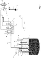
- the frothing device shown has a steam lance 1 which is connected via a valve arrangement 2 to a hot water boiler 3 serving as a steam generator. Between the valve arrangement 2 and the steam lance 1 there is also a venturi nozzle 4, which is also referred to as a venturi injector, into which an air line 5 opens, which is provided with a fast-acting solenoid valve 6, the air valve.
- a venturi nozzle 4 which is also referred to as a venturi injector, into which an air line 5 opens, which is provided with a fast-acting solenoid valve 6, the air valve.
- the valve arrangement 2 comprises three parallel-connected solenoid valves 2a, 2b, 2c, with either valve 2a being opened alone in order to output a smaller volume of steam, or all three valves being opened in order to output a larger volume of steam. Accordingly, the solenoid valve 2a can be controlled separately, the valves 2b, 2c are electrically connected to one another and are only controlled together.
- the boiler 3 has two separate heaters 7a, 7b, which in the exemplary embodiment each have a heat output of 2.8 kW and can be controlled and regulated separately. On the one hand, this allows a sufficient amount of steam to be produced quickly. On the other hand, the temperature and the steam pressure inside the boiler 3 can be easily controlled in stand-by mode.
- the boiler 3 has a temperature sensor 8, which is designed as an NTC resistor in the exemplary embodiment, and a level sensor 9, which ensures that the boiler 3 is filled with sufficient water.
- a pressure relief valve 10 opens when a maximum allowable pressure is exceeded inside the boiler 3 .
- a pressure sensor 12 (manometer), with which the pressure in the steam line 11 is measured, is also connected to the steam lines 11 leading from the boiler 3 to the valve arrangement 2 .
- the temperature sensor 14 on the steam lance 1, which is also designed as an NTC resistor in the exemplary embodiment.
- the downwardly open end of the steam lance 1 is provided with a steam nozzle 1a which is immersed in a milk vessel to froth milk contained therein.
- the temperature sensor 14 measures the temperature at the end of the steam lance 1 and thus the temperature of the milk to be frothed.
- the temperature sensor 14 therefore enables the frothing process to be carried out as a function of the milk temperature up to a desired end temperature.
- the air valve 6 is controlled with an intermittent signal, in particular a square-wave signal, and opens and closes in rapid succession at a clock rate of, for example, 10 to 20 Hz.
- a suitable high-frequency switching valve can preferably also be switched with an even higher clock frequency of around 40 Hz.
- the pulse duty factor ie the ratio between the opening duration and the period of an opening cycle, can be set.
- the air supply can also be closed completely if only steam is to be dispensed to heat milk or to reheat milk froth.
- the valve 6 is controlled via a control circuit 20.
- the temperature sensor 14, with which the milk temperature can be measured, is also connected to this circuit.
- the control circuit 20 also controls the opening and closing of the solenoid valves 2a, 2b and 2c of the valve block 2.
- the operation of the boiler 3 can also be controlled via the control circuit 20.
- the control circuit 20 controls the heaters 7a, 7b and reads the signals from the temperature sensor 8 and the filling level sensor 9 as well as from the manometer 12.
- the control circuit 20 initially only opens the valve 2a of the valve block 2, so that a smaller flow of steam is output to the steam lance 1.
- the valve 6 can be controlled with a lower pulse duty factor, so that less air is added to the vapor.
- additional steam can be added via the valves 2b, 2c, ie steam can be output with a higher volume flow.
- the air supply can be correspondingly increased via the valve 6 by lengthening the pulse duty factor.
- the air supply is closed via the valve 6 .
- all steam valves 2a, 2b, 2c are closed and the frothing process is finished.
- the controller 20 automatically detects the point in time at which the air valve 6 should be closed based on the temperature and on the basis of empirical values.
- the controller 20 also recognizes from the rise in temperature whether only a small quantity of milk or a larger quantity of milk is to be frothed. If there is little milk in a vessel placed under the steam wand 1, the temperature rises more quickly when just opening the valve 2a for a small supply of steam than with a larger quantity of milk. Thus, the controller 20 can decide to leave the valves 2b, 2c for the steam addition closed if only a small quantity of milk is to be frothed and a rapid rise in temperature has accordingly been recognized. This measure will help prevent the milk from splattering.
- FIG 2 the principle of the Venturi nozzle 4 is shown again in detail.
- the steam supply line is connected to the venturi nozzle 4 at the upper end 4a.
- the steam flow 15 entering at the upper end 4a is accelerated due to the constriction 4b and, due to the Venturi effect, generates a negative pressure at the side opening 4c, through which an air flow 16 is sucked in when the air valve 6 is open and together with the steam flow 15 at the lower end 4d the Venturi nozzle 4 is output.
- the functional principle corresponds to that of a water jet pump.
- the device explained for frothing milk is preferably installed in coffee machines in the catering sector, in particular in portafilter machines or other counter devices.
- the boiler 3 can be used here at the same time for dispensing hot water for tea or for brewing fresh coffee drinks. It is also possible to keep the steam system with the boiler 3 separate from the brewing device of a coffee machine and to provide a separate hot water generator for the latter.
- the device for frothing milk can of course also be designed as a separate add-on device.
Landscapes
- Engineering & Computer Science (AREA)
- Food Science & Technology (AREA)
- Apparatus For Making Beverages (AREA)
Claims (11)
- Dispositif pour faire mousser du lait, comprenant une lance de vapeur tubulaire (1) dotée d'une extrémité ouverte (la) pointée vers le bas, pour une introduction dans un contenant à lait, un générateur de vapeur (3) qui est en communication avec la lance de vapeur (1) par le biais d'une conduite de vapeur (11), une buse venturi (4) agencée dans la conduite de vapeur (11), dans lequel débouche une conduite d'amenée d'air (5), et un agencement de soupape (2) agencé dans la conduite de vapeur (11) en amont de la buse venturi (4) pour ouvrir et fermer la conduite de vapeur (11),dans lequel la conduite d'amenée d'air (5) est pourvue d'une soupape d'air (6) à commande électrique qui, en fonction d'un signal de commande, limite un flux d'air aspiré par la buse venturi (4) à un débit volumétrique réglable par la soupape d'air (6),caractérisé en ce quela soupape d'air (6) est réalisée sous la forme d'une soupape d'air cadencée (6) qui s'ouvre et se ferme en fonction d'un signal de commutation périodique pour produire un flux d'air pulsé avec un débit moyen, et avec un circuit de commande électrique (20) pour produire le signal de commutation périodique, dans lequel une fréquence et/ou un rapport cyclique du signal de commutation périodique peuvent être réglés pour un réglage du débit moyen.
- Dispositif selon la revendication 1, dans lequel l'agencement de soupape (2) présente au moins deux niveaux d'ouverture, via lesquels un flux de vapeur avec au moins un premier débit inférieur ou un second débit d'écoulement supérieur peut être libéré de manière sélective.
- Dispositif selon la revendication 2, dans lequel l'agencement de soupape (2) comprend deux ou plusieurs soupapes magnétiques pouvant être commandées électriquement (2a, 2b, 2c) qui sont connectées en parallèle entre elles, et dans lequel le premier niveau d'ouverture est réalisé en ouvrant une seule des soupapes magnétiques (2a) et le second niveau d'ouverture est réalisé en ouvrant au moins deux des soupapes magnétiques (2a, 2b, 2c).
- Dispositif selon la revendication 2 ou 3, dans lequel le circuit de commande (20) est agencé pour commander la soupape d'air cadencée (6) de manière à aspirer un flux d'air présentant un débit volumétrique moyen inférieur pendant que l'agencement de soupape (2) est ouvert dans le premier niveau d'ouverture, et pendant que l'agencement de soupape (2) est ouvert dans le second niveau d'ouverture, un flux d'air avec un débit volumétrique moyen plus élevé est aspiré.
- Dispositif selon l'une quelconque des revendications 2 à 4, dans lequel le circuit de commande (20) est agencé pour ouvrir l'agencement de soupape (2) afin de faire mousser du lait d'abord dans le premier niveau d'ouverture, pour libérer un écoulement de vapeur à débit d'écoulement inférieur, puis, après un laps de temps prédéterminé ou prédéfini, pour ouvrir l'agencement de soupape (2) dans le second niveau d'ouverture afin de libérer un écoulement de vapeur à un débit d'écoulement plus élevé.
- Dispositif selon l'une quelconque des revendications 2 à 5, dans lequel le circuit de commande (20) est conçu pour faire mousser et chauffer du lait pendant une phase de moussage, pour ouvrir l'agencement de soupape (2) dans la conduite de vapeur (11) et pour commander la soupape d'air cadencée (6) pour aspirer de l'air dans l'écoulement de vapeur via la conduite d'air (5) et fermer la soupape d'air (6) dans une phase de réchauffage ultérieure, mais pour maintenir l'agencement de soupape (2) ouvert dans la conduite de vapeur (11).
- Dispositif selon l'une quelconque des revendications précédentes, dans lequel un capteur de température (14) est agencé au niveau de la lance de vapeur (1), qui mesure la température du liquide environnant, et le dispositif de commande (20) est conçu pour commander la soupape d'air (6) en fonction de la température mesurée.
- Dispositif selon les revendications 6 et 7, dans lequel le dispositif de commande (20) est conçu pour effectuer la phase de moussage jusqu'à ce qu'une première température pouvant être prédéterminée soit atteinte et pour effectuer la phase de réchauffage ultérieure jusqu'à ce qu'une seconde température pouvant être prédéterminée soit atteinte.
- Dispositif selon l'une quelconque des revendications précédentes, dans lequel de l'air est aspiré à partir de la pression atmosphérique ambiante via la conduite d'air (5) dans la buse venturi (4) en raison de l'écoulement de vapeur (15).
- Dispositif selon l'une quelconque des revendications précédentes, dans lequel le circuit de commande électrique (20) est adapté pour produire le signal de commutation à une fréquence comprise entre 5 et 50 Hz, de préférence entre 10 et 40 Hz.
- Dispositif selon l'une quelconque des revendications précédentes, dans lequel le générateur de vapeur est réalisé sous la forme d'une chaudière (3) avec un chauffage électrique (7a, 7b).
Applications Claiming Priority (2)
| Application Number | Priority Date | Filing Date | Title |
|---|---|---|---|
| DE102018101025.7A DE102018101025A1 (de) | 2018-01-18 | 2018-01-18 | Vorrichtung zum aufschäumen von milch |
| PCT/EP2018/081998 WO2019141409A1 (fr) | 2018-01-18 | 2018-11-21 | Dispositif pour faire mousser du lait |
Publications (2)
| Publication Number | Publication Date |
|---|---|
| EP3740106A1 EP3740106A1 (fr) | 2020-11-25 |
| EP3740106B1 true EP3740106B1 (fr) | 2022-10-19 |
Family
ID=64456967
Family Applications (1)
| Application Number | Title | Priority Date | Filing Date |
|---|---|---|---|
| EP18807936.2A Active EP3740106B1 (fr) | 2018-01-18 | 2018-11-21 | Dispositif pour faire mousser du lait |
Country Status (5)
| Country | Link |
|---|---|
| EP (1) | EP3740106B1 (fr) |
| CN (1) | CN214317792U (fr) |
| DE (1) | DE102018101025A1 (fr) |
| ES (1) | ES2930108T3 (fr) |
| WO (1) | WO2019141409A1 (fr) |
Families Citing this family (2)
| Publication number | Priority date | Publication date | Assignee | Title |
|---|---|---|---|---|
| DE202019104349U1 (de) * | 2019-08-07 | 2020-11-10 | Eversys Ag | Vorrichtung zum Erhitzen und Aufschäumen einer Flüssigkeit, insbesondere eines Getränks |
| DE102022109867B3 (de) | 2022-04-25 | 2023-05-11 | Franke Kaffeemaschinen Ag | Heißgetränkezubereitungsvorrichtung mit Dampflanze |
Citations (1)
| Publication number | Priority date | Publication date | Assignee | Title |
|---|---|---|---|---|
| EP0472272B1 (fr) * | 1990-06-25 | 1996-09-11 | Caffe Acorto Inc. | Machine à café automatique |
Family Cites Families (8)
| Publication number | Priority date | Publication date | Assignee | Title |
|---|---|---|---|---|
| EP1776905B1 (fr) | 2005-10-21 | 2007-12-26 | Gruppo Cimbali S.p.A. | Procédé pour chauffer et mousser du lait et dispositif pour exécuter ce procédé |
| PT1949829E (pt) | 2007-01-23 | 2009-06-04 | Rancilio Macchine Caffe | Dispositivo para aquecer e/ou produzir espuma numa bebida |
| EP2025270B1 (fr) * | 2007-08-16 | 2017-04-12 | Cafina AG | Dispositif destiné à faire mousser et chauffer du lait |
| IT1396821B1 (it) * | 2009-10-22 | 2012-12-14 | Elektra S R L | Metodo di montatura del latte e dispositivo montalatte per attuare il metodo. |
| DE102011077776B4 (de) | 2011-06-17 | 2013-11-14 | Wmf Württembergische Metallwarenfabrik Ag | Vorrichtung zum Erhitzen und Aufschäumen eines Getränkeprodukts |
| DE102015117650B4 (de) * | 2015-10-16 | 2020-06-25 | Eversys Holding Sa | Vorrichtung und Verfahren zum Erhitzen und Aufschäumen einer Flüssigkeit, insbesondere eines Getränks |
| ITUB20155131A1 (it) * | 2015-10-21 | 2017-04-21 | Elektra S R L | Macchina da caffe' professionale. |
| US10568455B2 (en) * | 2016-06-22 | 2020-02-25 | Melitta Professional Coffee Solutions GmbH & Co. KG | Method and device for producing milk-air emulsions |
-
2018
- 2018-01-18 DE DE102018101025.7A patent/DE102018101025A1/de not_active Ceased
- 2018-11-21 ES ES18807936T patent/ES2930108T3/es active Active
- 2018-11-21 CN CN201890001454.2U patent/CN214317792U/zh active Active
- 2018-11-21 EP EP18807936.2A patent/EP3740106B1/fr active Active
- 2018-11-21 WO PCT/EP2018/081998 patent/WO2019141409A1/fr unknown
Patent Citations (1)
| Publication number | Priority date | Publication date | Assignee | Title |
|---|---|---|---|---|
| EP0472272B1 (fr) * | 1990-06-25 | 1996-09-11 | Caffe Acorto Inc. | Machine à café automatique |
Also Published As
| Publication number | Publication date |
|---|---|
| DE102018101025A1 (de) | 2019-07-18 |
| ES2930108T3 (es) | 2022-12-05 |
| CN214317792U (zh) | 2021-10-01 |
| EP3740106A1 (fr) | 2020-11-25 |
| WO2019141409A1 (fr) | 2019-07-25 |
Similar Documents
| Publication | Publication Date | Title |
|---|---|---|
| EP2025270B1 (fr) | Dispositif destiné à faire mousser et chauffer du lait | |
| DE602005004032T2 (de) | Verfahren zum Aufwärmen und Schäumen von Milch und Vorrichtung um dieses Verfahren auszuführen | |
| EP2636343B1 (fr) | Dispositif et procédé de fabrication de mousse de lait et/ou de lait chauffé | |
| EP1833337B1 (fr) | Machine a cafe | |
| DE102014216534B3 (de) | Vorrichtung und Verfahren zum Aufschäumen eines flüssigen Lebensmittels, insbesondere von Milch | |
| DE102009041809B4 (de) | Vorrichtung und Verfahren zum Aufschäumen eines flüssigen Lebensmittels, insbesondere von Milch | |
| EP2755533B1 (fr) | Procédé de préparation d'une boisson à base de café ainsi que machine à café pour la mise en oeuvre de ce procédé | |
| EP2229851B1 (fr) | Dispositif de moussage | |
| EP0781520A1 (fr) | Machine à préparer des infusions | |
| EP2368467B1 (fr) | Machine de préparation de boissons électrique | |
| EP1793717B1 (fr) | Machine a cafe et procede de commande | |
| DE202009007945U1 (de) | Vorrichtung, die zur Verwendung zum Schaumigschlagen von Milch geeignet ist | |
| EP0523278A1 (fr) | Machine à café expresso | |
| EP0635230A1 (fr) | Machine à café | |
| EP2798989B1 (fr) | Dispositif de préparation de boisson, des moyens de chauffage du lait ainsi que le procédé d'opération | |
| DE102011084901A1 (de) | Vorrichtung zur Ausgabe von Milch und Verfahren zum Erwärmen von Milch | |
| EP0600826B1 (fr) | Dispositif pour produire du lait moussé pour du café cappuccino ou boissons similaires | |
| EP3694381A1 (fr) | Dispositif de création de mousse de lait | |
| DE102017102956A1 (de) | Vorrichtung zur Ausgabe von Heißwasser | |
| EP3740106B1 (fr) | Dispositif pour faire mousser du lait | |
| EP0797945A1 (fr) | Machine à café filtre | |
| EP1833340B1 (fr) | Machine de preparation de boissons chaudes | |
| DE202008016375U1 (de) | Einrichtung zum Aufschäumen einer Flüssigkeit, wie z.B. Milch | |
| DE102019203584B3 (de) | Kaffeeautomat | |
| DE2421620A1 (de) | Vorrichtung zum selbsttaetigen herstellen von getraenken |
Legal Events
| Date | Code | Title | Description |
|---|---|---|---|
| STAA | Information on the status of an ep patent application or granted ep patent |
Free format text: STATUS: UNKNOWN |
|
| STAA | Information on the status of an ep patent application or granted ep patent |
Free format text: STATUS: THE INTERNATIONAL PUBLICATION HAS BEEN MADE |
|
| PUAI | Public reference made under article 153(3) epc to a published international application that has entered the european phase |
Free format text: ORIGINAL CODE: 0009012 |
|
| STAA | Information on the status of an ep patent application or granted ep patent |
Free format text: STATUS: REQUEST FOR EXAMINATION WAS MADE |
|
| 17P | Request for examination filed |
Effective date: 20200723 |
|
| AK | Designated contracting states |
Kind code of ref document: A1 Designated state(s): AL AT BE BG CH CY CZ DE DK EE ES FI FR GB GR HR HU IE IS IT LI LT LU LV MC MK MT NL NO PL PT RO RS SE SI SK SM TR |
|
| AX | Request for extension of the european patent |
Extension state: BA ME |
|
| DAV | Request for validation of the european patent (deleted) | ||
| DAX | Request for extension of the european patent (deleted) | ||
| GRAP | Despatch of communication of intention to grant a patent |
Free format text: ORIGINAL CODE: EPIDOSNIGR1 |
|
| STAA | Information on the status of an ep patent application or granted ep patent |
Free format text: STATUS: GRANT OF PATENT IS INTENDED |
|
| INTG | Intention to grant announced |
Effective date: 20220607 |
|
| GRAS | Grant fee paid |
Free format text: ORIGINAL CODE: EPIDOSNIGR3 |
|
| GRAA | (expected) grant |
Free format text: ORIGINAL CODE: 0009210 |
|
| STAA | Information on the status of an ep patent application or granted ep patent |
Free format text: STATUS: THE PATENT HAS BEEN GRANTED |
|
| AK | Designated contracting states |
Kind code of ref document: B1 Designated state(s): AL AT BE BG CH CY CZ DE DK EE ES FI FR GB GR HR HU IE IS IT LI LT LU LV MC MK MT NL NO PL PT RO RS SE SI SK SM TR |
|
| REG | Reference to a national code |
Ref country code: GB Ref legal event code: FG4D Free format text: NOT ENGLISH |
|
| REG | Reference to a national code |
Ref country code: CH Ref legal event code: EP |
|
| REG | Reference to a national code |
Ref country code: IE Ref legal event code: FG4D Free format text: LANGUAGE OF EP DOCUMENT: GERMAN |
|
| REG | Reference to a national code |
Ref country code: DE Ref legal event code: R096 Ref document number: 502018010883 Country of ref document: DE |
|
| REG | Reference to a national code |
Ref country code: AT Ref legal event code: REF Ref document number: 1525029 Country of ref document: AT Kind code of ref document: T Effective date: 20221115 |
|
| REG | Reference to a national code |
Ref country code: NL Ref legal event code: FP |
|
| REG | Reference to a national code |
Ref country code: ES Ref legal event code: FG2A Ref document number: 2930108 Country of ref document: ES Kind code of ref document: T3 Effective date: 20221205 |
|
| REG | Reference to a national code |
Ref country code: LT Ref legal event code: MG9D |
|
| PG25 | Lapsed in a contracting state [announced via postgrant information from national office to epo] |
Ref country code: SE Free format text: LAPSE BECAUSE OF FAILURE TO SUBMIT A TRANSLATION OF THE DESCRIPTION OR TO PAY THE FEE WITHIN THE PRESCRIBED TIME-LIMIT Effective date: 20221019 Ref country code: PT Free format text: LAPSE BECAUSE OF FAILURE TO SUBMIT A TRANSLATION OF THE DESCRIPTION OR TO PAY THE FEE WITHIN THE PRESCRIBED TIME-LIMIT Effective date: 20230220 Ref country code: NO Free format text: LAPSE BECAUSE OF FAILURE TO SUBMIT A TRANSLATION OF THE DESCRIPTION OR TO PAY THE FEE WITHIN THE PRESCRIBED TIME-LIMIT Effective date: 20230119 Ref country code: LT Free format text: LAPSE BECAUSE OF FAILURE TO SUBMIT A TRANSLATION OF THE DESCRIPTION OR TO PAY THE FEE WITHIN THE PRESCRIBED TIME-LIMIT Effective date: 20221019 Ref country code: FI Free format text: LAPSE BECAUSE OF FAILURE TO SUBMIT A TRANSLATION OF THE DESCRIPTION OR TO PAY THE FEE WITHIN THE PRESCRIBED TIME-LIMIT Effective date: 20221019 |
|
| PG25 | Lapsed in a contracting state [announced via postgrant information from national office to epo] |
Ref country code: RS Free format text: LAPSE BECAUSE OF FAILURE TO SUBMIT A TRANSLATION OF THE DESCRIPTION OR TO PAY THE FEE WITHIN THE PRESCRIBED TIME-LIMIT Effective date: 20221019 Ref country code: PL Free format text: LAPSE BECAUSE OF FAILURE TO SUBMIT A TRANSLATION OF THE DESCRIPTION OR TO PAY THE FEE WITHIN THE PRESCRIBED TIME-LIMIT Effective date: 20221019 Ref country code: LV Free format text: LAPSE BECAUSE OF FAILURE TO SUBMIT A TRANSLATION OF THE DESCRIPTION OR TO PAY THE FEE WITHIN THE PRESCRIBED TIME-LIMIT Effective date: 20221019 Ref country code: IS Free format text: LAPSE BECAUSE OF FAILURE TO SUBMIT A TRANSLATION OF THE DESCRIPTION OR TO PAY THE FEE WITHIN THE PRESCRIBED TIME-LIMIT Effective date: 20230219 Ref country code: HR Free format text: LAPSE BECAUSE OF FAILURE TO SUBMIT A TRANSLATION OF THE DESCRIPTION OR TO PAY THE FEE WITHIN THE PRESCRIBED TIME-LIMIT Effective date: 20221019 Ref country code: GR Free format text: LAPSE BECAUSE OF FAILURE TO SUBMIT A TRANSLATION OF THE DESCRIPTION OR TO PAY THE FEE WITHIN THE PRESCRIBED TIME-LIMIT Effective date: 20230120 |
|
| P01 | Opt-out of the competence of the unified patent court (upc) registered |
Effective date: 20230526 |
|
| REG | Reference to a national code |
Ref country code: DE Ref legal event code: R097 Ref document number: 502018010883 Country of ref document: DE |
|
| REG | Reference to a national code |
Ref country code: BE Ref legal event code: MM Effective date: 20221130 |
|
| PG25 | Lapsed in a contracting state [announced via postgrant information from national office to epo] |
Ref country code: SM Free format text: LAPSE BECAUSE OF FAILURE TO SUBMIT A TRANSLATION OF THE DESCRIPTION OR TO PAY THE FEE WITHIN THE PRESCRIBED TIME-LIMIT Effective date: 20221019 Ref country code: RO Free format text: LAPSE BECAUSE OF FAILURE TO SUBMIT A TRANSLATION OF THE DESCRIPTION OR TO PAY THE FEE WITHIN THE PRESCRIBED TIME-LIMIT Effective date: 20221019 Ref country code: MC Free format text: LAPSE BECAUSE OF FAILURE TO SUBMIT A TRANSLATION OF THE DESCRIPTION OR TO PAY THE FEE WITHIN THE PRESCRIBED TIME-LIMIT Effective date: 20221019 Ref country code: EE Free format text: LAPSE BECAUSE OF FAILURE TO SUBMIT A TRANSLATION OF THE DESCRIPTION OR TO PAY THE FEE WITHIN THE PRESCRIBED TIME-LIMIT Effective date: 20221019 Ref country code: DK Free format text: LAPSE BECAUSE OF FAILURE TO SUBMIT A TRANSLATION OF THE DESCRIPTION OR TO PAY THE FEE WITHIN THE PRESCRIBED TIME-LIMIT Effective date: 20221019 Ref country code: CZ Free format text: LAPSE BECAUSE OF FAILURE TO SUBMIT A TRANSLATION OF THE DESCRIPTION OR TO PAY THE FEE WITHIN THE PRESCRIBED TIME-LIMIT Effective date: 20221019 |
|
| PLBE | No opposition filed within time limit |
Free format text: ORIGINAL CODE: 0009261 |
|
| STAA | Information on the status of an ep patent application or granted ep patent |
Free format text: STATUS: NO OPPOSITION FILED WITHIN TIME LIMIT |
|
| PG25 | Lapsed in a contracting state [announced via postgrant information from national office to epo] |
Ref country code: SK Free format text: LAPSE BECAUSE OF FAILURE TO SUBMIT A TRANSLATION OF THE DESCRIPTION OR TO PAY THE FEE WITHIN THE PRESCRIBED TIME-LIMIT Effective date: 20221019 Ref country code: LU Free format text: LAPSE BECAUSE OF NON-PAYMENT OF DUE FEES Effective date: 20221121 Ref country code: AL Free format text: LAPSE BECAUSE OF FAILURE TO SUBMIT A TRANSLATION OF THE DESCRIPTION OR TO PAY THE FEE WITHIN THE PRESCRIBED TIME-LIMIT Effective date: 20221019 |
|
| 26N | No opposition filed |
Effective date: 20230720 |
|
| PG25 | Lapsed in a contracting state [announced via postgrant information from national office to epo] |
Ref country code: IE Free format text: LAPSE BECAUSE OF NON-PAYMENT OF DUE FEES Effective date: 20221121 |
|
| PG25 | Lapsed in a contracting state [announced via postgrant information from national office to epo] |
Ref country code: SI Free format text: LAPSE BECAUSE OF FAILURE TO SUBMIT A TRANSLATION OF THE DESCRIPTION OR TO PAY THE FEE WITHIN THE PRESCRIBED TIME-LIMIT Effective date: 20221019 Ref country code: FR Free format text: LAPSE BECAUSE OF NON-PAYMENT OF DUE FEES Effective date: 20221219 Ref country code: BE Free format text: LAPSE BECAUSE OF NON-PAYMENT OF DUE FEES Effective date: 20221130 |
|
| PGFP | Annual fee paid to national office [announced via postgrant information from national office to epo] |
Ref country code: NL Payment date: 20231122 Year of fee payment: 6 |
|
| PGFP | Annual fee paid to national office [announced via postgrant information from national office to epo] |
Ref country code: GB Payment date: 20231123 Year of fee payment: 6 |
|
| PGFP | Annual fee paid to national office [announced via postgrant information from national office to epo] |
Ref country code: ES Payment date: 20231215 Year of fee payment: 6 |
|
| PGFP | Annual fee paid to national office [announced via postgrant information from national office to epo] |
Ref country code: IT Payment date: 20231130 Year of fee payment: 6 Ref country code: DE Payment date: 20230926 Year of fee payment: 6 Ref country code: CH Payment date: 20231201 Year of fee payment: 6 |
|
| PG25 | Lapsed in a contracting state [announced via postgrant information from national office to epo] |
Ref country code: CY Free format text: LAPSE BECAUSE OF FAILURE TO SUBMIT A TRANSLATION OF THE DESCRIPTION OR TO PAY THE FEE WITHIN THE PRESCRIBED TIME-LIMIT Effective date: 20221019 |