EP3740106B1 - Vorrichtung zum aufschäumen von milch - Google Patents
Vorrichtung zum aufschäumen von milch Download PDFInfo
- Publication number
- EP3740106B1 EP3740106B1 EP18807936.2A EP18807936A EP3740106B1 EP 3740106 B1 EP3740106 B1 EP 3740106B1 EP 18807936 A EP18807936 A EP 18807936A EP 3740106 B1 EP3740106 B1 EP 3740106B1
- Authority
- EP
- European Patent Office
- Prior art keywords
- steam
- air
- flow
- valve
- milk
- Prior art date
- Legal status (The legal status is an assumption and is not a legal conclusion. Google has not performed a legal analysis and makes no representation as to the accuracy of the status listed.)
- Active
Links
Images

Classifications
-
- A—HUMAN NECESSITIES
- A47—FURNITURE; DOMESTIC ARTICLES OR APPLIANCES; COFFEE MILLS; SPICE MILLS; SUCTION CLEANERS IN GENERAL
- A47J—KITCHEN EQUIPMENT; COFFEE MILLS; SPICE MILLS; APPARATUS FOR MAKING BEVERAGES
- A47J31/00—Apparatus for making beverages
- A47J31/44—Parts or details or accessories of beverage-making apparatus
- A47J31/4489—Steam nozzles, e.g. for introducing into a milk container to heat and foam milk
-
- A—HUMAN NECESSITIES
- A47—FURNITURE; DOMESTIC ARTICLES OR APPLIANCES; COFFEE MILLS; SPICE MILLS; SUCTION CLEANERS IN GENERAL
- A47J—KITCHEN EQUIPMENT; COFFEE MILLS; SPICE MILLS; APPARATUS FOR MAKING BEVERAGES
- A47J31/00—Apparatus for making beverages
- A47J31/44—Parts or details or accessories of beverage-making apparatus
- A47J31/46—Dispensing spouts, pumps, drain valves or like liquid transporting devices
- A47J31/461—Valves, e.g. drain valves
Definitions
- the present invention relates to a device for frothing milk, comprising a tubular steam lance with an open end pointing downwards for insertion into a milk vessel, a steam generator which is connected to the steam lance via a steam line, a venturi nozzle arranged in the steam line, in which opens into an air supply line, and a valve arrangement arranged upstream of the venturi nozzle in the steam line for opening and closing the steam line.
- Coffee machines are often equipped with a device for producing milk froth in order to be able to prepare coffee beverages such as cappuccino or latte macchiato.
- a device for producing milk froth in order to be able to prepare coffee beverages such as cappuccino or latte macchiato.
- so-called steam lances are also often provided, via which steam can be released, with which milk can be frothed externally in a milk container.
- the flow of steam is admixed with air, which is required for frothing the milk.
- a device with a steam lance is known, in which air is sucked into the steam line via a Venturi nozzle.
- a steam lance in which air is sucked in via a venturi nozzle and the amount of air can be regulated via a manually or electromechanically adjustable throttle is EP 2 025 270 A2 known.
- compressed air is used in addition to steam to froth milk.
- a system is described in which blasts of compressed air, each lasting one second, are fed into the steam supply line of a steam lance via a compressor.
- the EP 2 534 986 B1 describes a system in which compressed air is introduced into the boiler intended for steam generation.
- the air line is provided with an electrically controllable air valve which, depending on a control signal, limits an air flow sucked in via the Venturi nozzle to a volumetric flow that can be set via the air valve.
- the air valve is designed as a clocked air valve which opens and closes as a function of a periodic switching signal in order to generate a pulsed air flow with an average volume flow.
- the device has an electrical control circuit for generating the periodic switching signal, a frequency and/or a pulse duty factor of the periodic switching signal being adjustable for metering the air supply or for setting the average volume flow.
- the amount of air supplied to the stream of steam can be set and changed in a simple manner during the duration of a foaming process.
- Studies by the applicant have shown that astonishingly better foaming results are achieved with the air flow pulsed at high frequency than with compressed air or a continuously sucked-in air flow.
- the air valve can also be designed as a motor-driven continuous valve, in particular a needle valve.
- the valve arrangement for opening and closing the steam line has at least two opening stages, via which a steam flow can be released with at least a first, lower, and a second, higher flow rate.
- a steam stream with a lower flow rate can be used for a smaller quantity of product and at the start of a frothing process, so that the milk does not splash out of the frothing vessel. If, on the other hand, a larger amount of milk is frothed, and in particular after the resulting milk froth has already reached a certain volume, the amount of steam can be increased.
- Such a valve arrangement can preferably be constructed with two or more controllable solenoid valves which are connected in parallel to one another.
- the first opening stage can be realized by opening only one of the solenoid valves and the second opening stage can be realized by opening at least two of the solenoid valves.
- Such solenoid valves are available as integrated valve blocks at low cost, are easy to handle and reliable in operation.
- the possibility of gradually varying the flow rate of the steam also makes it possible to start frothing milk with a flow of steam at a lower flow rate in a first opening stage and then, after a predetermined or specifiable period of time, to open the valve arrangement in the second opening stage. to release higher flow rate vapor flow. This prevents the milk, which is initially still liquid, from splashing and, after it has increased in volume, continues to be frothed with an increased amount of steam.
- the use of the electronically controllable, timed air valve also makes it possible to first open the valve arrangement in the steam line during a frothing phase and to activate the timed air valve for frothing and heating milk in order to suck air into the steam flow via the air line and in a subsequent reheating phase to close the air valve but keep the valve assembly in the vapor line open.
- the initially cold milk is first frothed with the air-enriched steam and then further heated with only steam. This prevents too much air from being introduced into the milk froth, which would make it too coarse-pored or could collapse.
- the steam without the addition of air ensures that the previously introduced volume of air is further distributed and refined in the milk froth, resulting in a creamy, fine-pored milk froth at the desired temperature.
- a temperature sensor is arranged on the steam lance, which measures the temperature of the surrounding liquid. This enables automatic control of the steam injection up to a desired final temperature. It is particularly advantageous here if not only the valve arrangement in the steam supply line but also the air valve is controlled via the temperature. In particular, when a specific, predetermined or predeterminable temperature is reached, the air supply can be throttled or closed. This takes into account the finding that when a certain temperature difference is reached from the original starting temperature to the current temperature with a known heat capacity of the milk and a known temperature and quantity of steam as well as a known cycle ratio of the air valve, a determinable quantity of air was introduced into the milk to be frothed. Thus, based on the current temperature, it can be determined whether the appropriate amount of air has already been introduced for a specific amount of milk to be frothed, and the air supply can be throttled after the appropriate amount of air has been reached.
- the foaming phase can be carried out until a first, definable temperature is reached and the subsequent reheating phase below Reduction or shutdown of the air supply take place until a second predetermined temperature is reached.
- the Venturi nozzle has a structure of a known type with a constriction provided in the steam line, which leads to an increase in the steam velocity in the area of the constriction, and an air line opening into or just behind the constriction.
- a constriction provided in the steam line, which leads to an increase in the steam velocity in the area of the constriction, and an air line opening into or just behind the constriction.
- air is sucked in via the air line from the ambient atmospheric pressure.
- An air filter can also be arranged in the air line, but this is not absolutely necessary.
- the clocked air valve operates at a high frequency of between 5 and 50 Hz, preferably between 10 and 40 Hz. Tests by the applicant have shown that the best results when frothing milk are produced with these comparatively fast switching cycles. It is possible, but not essential, to vary the switching frequency.
- the amount of air is preferably regulated by adapting the pulse duty factor, ie the length of the opening time per switching cycle.
- a boiler with an electric heater is preferably used as the steam generator.
- a sufficiently large amount of steam can be kept available, which is required for frothing normal amounts of milk.
- a flow heater is also possible to use as the steam generator.
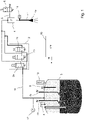
- the frothing device shown has a steam lance 1 which is connected via a valve arrangement 2 to a hot water boiler 3 serving as a steam generator. Between the valve arrangement 2 and the steam lance 1 there is also a venturi nozzle 4, which is also referred to as a venturi injector, into which an air line 5 opens, which is provided with a fast-acting solenoid valve 6, the air valve.
- a venturi nozzle 4 which is also referred to as a venturi injector, into which an air line 5 opens, which is provided with a fast-acting solenoid valve 6, the air valve.
- the valve arrangement 2 comprises three parallel-connected solenoid valves 2a, 2b, 2c, with either valve 2a being opened alone in order to output a smaller volume of steam, or all three valves being opened in order to output a larger volume of steam. Accordingly, the solenoid valve 2a can be controlled separately, the valves 2b, 2c are electrically connected to one another and are only controlled together.
- the boiler 3 has two separate heaters 7a, 7b, which in the exemplary embodiment each have a heat output of 2.8 kW and can be controlled and regulated separately. On the one hand, this allows a sufficient amount of steam to be produced quickly. On the other hand, the temperature and the steam pressure inside the boiler 3 can be easily controlled in stand-by mode.
- the boiler 3 has a temperature sensor 8, which is designed as an NTC resistor in the exemplary embodiment, and a level sensor 9, which ensures that the boiler 3 is filled with sufficient water.
- a pressure relief valve 10 opens when a maximum allowable pressure is exceeded inside the boiler 3 .
- a pressure sensor 12 (manometer), with which the pressure in the steam line 11 is measured, is also connected to the steam lines 11 leading from the boiler 3 to the valve arrangement 2 .
- the temperature sensor 14 on the steam lance 1, which is also designed as an NTC resistor in the exemplary embodiment.
- the downwardly open end of the steam lance 1 is provided with a steam nozzle 1a which is immersed in a milk vessel to froth milk contained therein.
- the temperature sensor 14 measures the temperature at the end of the steam lance 1 and thus the temperature of the milk to be frothed.
- the temperature sensor 14 therefore enables the frothing process to be carried out as a function of the milk temperature up to a desired end temperature.
- the air valve 6 is controlled with an intermittent signal, in particular a square-wave signal, and opens and closes in rapid succession at a clock rate of, for example, 10 to 20 Hz.
- a suitable high-frequency switching valve can preferably also be switched with an even higher clock frequency of around 40 Hz.
- the pulse duty factor ie the ratio between the opening duration and the period of an opening cycle, can be set.
- the air supply can also be closed completely if only steam is to be dispensed to heat milk or to reheat milk froth.
- the valve 6 is controlled via a control circuit 20.
- the temperature sensor 14, with which the milk temperature can be measured, is also connected to this circuit.
- the control circuit 20 also controls the opening and closing of the solenoid valves 2a, 2b and 2c of the valve block 2.
- the operation of the boiler 3 can also be controlled via the control circuit 20.
- the control circuit 20 controls the heaters 7a, 7b and reads the signals from the temperature sensor 8 and the filling level sensor 9 as well as from the manometer 12.
- the control circuit 20 initially only opens the valve 2a of the valve block 2, so that a smaller flow of steam is output to the steam lance 1.
- the valve 6 can be controlled with a lower pulse duty factor, so that less air is added to the vapor.
- additional steam can be added via the valves 2b, 2c, ie steam can be output with a higher volume flow.
- the air supply can be correspondingly increased via the valve 6 by lengthening the pulse duty factor.
- the air supply is closed via the valve 6 .
- all steam valves 2a, 2b, 2c are closed and the frothing process is finished.
- the controller 20 automatically detects the point in time at which the air valve 6 should be closed based on the temperature and on the basis of empirical values.
- the controller 20 also recognizes from the rise in temperature whether only a small quantity of milk or a larger quantity of milk is to be frothed. If there is little milk in a vessel placed under the steam wand 1, the temperature rises more quickly when just opening the valve 2a for a small supply of steam than with a larger quantity of milk. Thus, the controller 20 can decide to leave the valves 2b, 2c for the steam addition closed if only a small quantity of milk is to be frothed and a rapid rise in temperature has accordingly been recognized. This measure will help prevent the milk from splattering.
- FIG 2 the principle of the Venturi nozzle 4 is shown again in detail.
- the steam supply line is connected to the venturi nozzle 4 at the upper end 4a.
- the steam flow 15 entering at the upper end 4a is accelerated due to the constriction 4b and, due to the Venturi effect, generates a negative pressure at the side opening 4c, through which an air flow 16 is sucked in when the air valve 6 is open and together with the steam flow 15 at the lower end 4d the Venturi nozzle 4 is output.
- the functional principle corresponds to that of a water jet pump.
- the device explained for frothing milk is preferably installed in coffee machines in the catering sector, in particular in portafilter machines or other counter devices.
- the boiler 3 can be used here at the same time for dispensing hot water for tea or for brewing fresh coffee drinks. It is also possible to keep the steam system with the boiler 3 separate from the brewing device of a coffee machine and to provide a separate hot water generator for the latter.
- the device for frothing milk can of course also be designed as a separate add-on device.
Landscapes
- Engineering & Computer Science (AREA)
- Food Science & Technology (AREA)
- Apparatus For Making Beverages (AREA)
Description
- Die vorliegende Erfindung betrifft eine Vorrichtung zum Aufschäumen von Milch umfassend eine rohrförmige Dampflanze mit einem nach unten weisenden, offenen Ende zum Einführen in ein Milchgefäß, einen Dampferzeuger, der über eine Dampfleitung mit der Dampflanze in Verbindung steht, eine in der Dampfleitung angeordnete Venturidüse, in die eine Luftzuleitung einmündet, und eine stromaufwärts der Venturidüse in der Dampfleitung angeordnete Ventilanordnung zum Öffnen und Schließen der Dampfleitung.
- Kaffeemaschinen werden häufig mit einer Vorrichtung zur Milchschaumerzeugung ausgestattet, um Kaffeegetränke wie Cappuccino oder Latte Macchiato zubereiten zu können. Neben Kaffeevollautomaten, die ein internes Milchsystem zur Ausgabe fertig aufgeschäumten Milchschaums aufweisen, werden häufig auch sogenannte Dampflanzen vorgesehen, über die Dampf ausgegeben werden kann, mit dem extern Milch in einem Milchgefäß aufgeschäumt werden kann. Hierbei ist bekannt, dass der Dampfströmung Luft beigemischt wird, die zum Aufschäumen der Milch benötigt wird. Aus der
EP 1 949 829 B1 ist beispielsweise eine Vorrichtung mit einer Dampflanze bekannt, bei der über eine Venturidüse in die Dampfleitung Luft mit angesaugt wird. - Eine Dampflanze, bei der Luft über eine Venturidüse angesaugt wird und die Luftmenge über eine manuell oder elektromechanisch verstellbare Drossel geregelt werden kann, ist aus der
EP 2 025 270 A2 bekannt. - Daneben ist auch bekannt, dass zusätzlich zum Dampf Druckluft verwendet wird, um Milch aufzuschäumen. Beispielsweise wird in der
EP 1 776 905 A1 ein System beschrieben, bei dem in die Dampfzuleitung einer Dampflanze über einen Kompressor Druckluftstöße von jeweils einer Sekunde Dauer zugeführt werden. In derEP 2 534 986 B1 ist ein System beschrieben, bei dem Druckluft in den zur Dampferzeugung vorgesehenen Boiler eingeleitet wird. - Vor allem die Verwendung von Druckluft birgt die Gefahr, dass beim Aufschäumen Milch aus dem Milchgefäß herausspritzt, insbesondere, wenn nur kleine Milchmengen aufgeschäumt werden sollen; aber auch beim Ansaugen von Luft über eine Venturidüse besteht das Problem, dass sich das Verhältnis von Luft und Dampf schlecht dosieren lässt und die aufgeschäumte Milch dadurch nicht die gewünschte Konsistenz und Temperatur erhält.
- Es ist daher eine Aufgabe der Erfindung, eine Vorrichtung zum Aufschäumen von Milch mittels einer Dampflanze anzugeben, die hinsichtlich ihrer Aufschäumeigenschaften verbessert ist.
- Die Aufgabe wird gelöst durch die Merkmale des Anspruchs 1. Vorteilhafte Ausgestaltungen sind den abhängigen Ansprüchen zu entnehmen.
- Erfindungsgemäß ist bei einer Vorrichtung der eingangs genannten Art vorgesehen, dass die Luftleitung mit einem elektrisch ansteuerbaren Luftventil versehen ist, welches in Abhängigkeit eines Steuersignals einen über die Venturidüse angesaugten Luftstrom auf einen über das Luftventil einstellbaren Volumenstrom begrenzt.
- Erfindungsgemäß ist das Luftventil als getaktetes Luftventil ausgeführt, welches in Abhängigkeit eines periodischen Schaltsignals öffnet und schließt, um einen gepulsten Luftstrom mit einem mittleren Volumenstrom zu erzeugen. Die Vorrichtung weist hierbei eine elektrische Steuerschaltung zur Erzeugung des periodischen Schaltsignals auf, wobei zur Dosierung der Luftzufuhr bzw. zur Einstellung des mittleren Volumenstroms eine Frequenz und/oder ein Tastverhältnis des periodischen Schaltsignals einstellbar sind.
- Durch die Verwendung eines elektrisch steuerbaren, insbesondere getakteten Luftventils lässt sich die dem Dampfstrom zugeführte Luftmenge auf einfache Weise während der Dauer eines Aufschäumvorgangs einstellen und verändern. Dabei haben Untersuchungen der Anmelderin ergeben, dass durch den mit hoher Frequenz gepulsten Luftstrom erstaunlicherweise bessere Aufschäumergebnisse erzielt werden, als mittels Druckluft oder einem kontinuierlich angesaugten Luftstrom.
- Alternativ kann das Luftventil jedoch auch als motorisch angetriebenes Stetigventil, insbesondere Nadelventil ausgeführt werden.
- Bei einer vorteilhaften Weiterbildung ist vorgesehen, dass die Ventilanordnung zum Öffnen und Schließen der Dampfleitung mindestens zwei Öffnungsstufen aufweist, über die ein Dampfstrom mit zumindest einer ersten niedrigeren und einer zweiten höheren Durchflussrate freigegeben werden kann. Auf diese Weise kann für eine kleinere Produktmenge und beim Beginn eines Aufschäumvorganges ein Dampfstrom mit geringerer Durchflussrate verwendet werden, damit die Milch nicht aus dem Aufschäumgefäß herausspritzt. Wird dagegen eine größere Menge Milch aufgeschäumt und insbesondere nachdem der entstehende Milchschaum bereits ein gewisses Volumen erreicht hat, kann die Dampfmenge erhöht werden.
- Eine solche Ventilanordnung kann vorzugsweise mit zwei oder mehr steuerbaren Magnetventilen aufgebaut werden, die zueinander parallelgeschaltet sind. Hierbei kann die erste Öffnungsstufe durch Öffnen nur eines der Magnetventile und die zweite Öffnungsstufe durch Öffnen von mindestens zwei der Magnetventile realisiert werden. Solche Magnetventile sind als integrierte Ventilblöcke kostengünstig verfügbar, einfach in der Handhabung und zuverlässig im Betrieb.
- Die Verwendung eines elektrisch ansteuerbaren, getakteten Luftventils sowie einer Ventilanordnung mit mehreren Öffnungsstufen für den Dampfstrom ermöglicht es, die Luftzufuhr in Abhängigkeit des Dampfstroms bzw. dessen Durchflussrate zu steuern. So ist es vorteilhaft, bei einer Öffnungsstufe für einen niedrigeren Dampfdurchsatz einen Luftstrom mit niedrigerem mittleren Volumenstrom einzustellen und bei einem höheren Dampfdurchsatz die Luftzufuhr durch entsprechende Ansteuerung des Luftventils, insbesondere durch längere Öffnungsphasen, zu erhöhen.
- Die Möglichkeit, die Durchflussrate des Dampfes stufenweise zu variieren, erlaubt es auch, zum Aufschäumen von Milch zunächst in einer ersten Öffnungsstufe mit einer Dampfströmung niedrigerer Durchflussrate zu beginnen und anschließend, nach einer vorgegebenen oder vorgebbaren Zeitspanne, die Ventilanordnung in der zweiten Öffnungsstufe zu öffnen, um eine Dampfströmung höherer Durchflussrate freizugeben. Hierdurch wird ein Verspritzen der zunächst noch flüssigen Milch verhindert und, nachdem diese an Volumen zugenommen hat, mit erhöhter Dampfmenge weiter aufgeschäumt.
- Die Verwendung des elektronisch steuerbaren, getakteten Luftventils ermöglicht es außerdem, zum Aufschäumen und Erwärmen von Milch zunächst während einer Aufschäumphase die Ventilanordnung in der Dampfleitung zu öffnen und das getaktete Luftventil anzusteuern, um über die Luftleitung Luft in die Dampfströmung anzusaugen, und in einer anschließenden Nacherwärmungsphase das Luftventil zu schließen, die Ventilanordnung in der Dampfleitung aber weiter geöffnet zu halten. Hierdurch wird die anfangs kalte Milch zunächst mit dem luftangereicherten Dampf aufgeschäumt und anschließend mit lediglich Dampf weiter erwärmt. Auf diese Weise wird verhindert, dass zu viel Luft in den Milchschaum eingebracht wird, wodurch dieser zu grobporig würde bzw. zusammenfallen könnte. In der Nacherwärmungsphase sorgt der Dampf ohne Luftzusatz dafür, das zuvor eingebrachte Luftvolumen im Milchschaum weiter zu verteilen und zu verfeinern, sodass ein cremiger, feinporiger Milchschaum der gewünschten Temperatur entsteht.
- Bei einer besonders vorteilhaften Weiterbildung der vorliegenden Erfindung ist an der Dampflanze ein Temperatursensor angeordnet, der die Temperatur umgebender Flüssigkeit misst. Dies ermöglicht eine automatische Steuerung der Dampfeinleitung bis zu einer gewünschten Endtemperatur. Besonders vorteilhaft ist hierbei, wenn über die Temperatur nicht nur die Ventilanordnung in der Dampfzuleitung, sondern auch das Luftventil gesteuert wird. Insbesondere kann bei Erreichen einer bestimmten, vorgegebenen bzw. vorgebbaren Temperatur die Luftzufuhr gedrosselt oder geschlossen werden. Dies trägt der Erkenntnis Rechnung, dass bei Erreichen einer bestimmten Temperaturdifferenz von der ursprünglichen Ausgangstemperatur bis zur aktuellen Temperatur bei bekannter Wärmekapazität der Milch und bekannter Temperatur und Menge des Dampfes sowie bei bekanntem Taktungsverhältnis des Luftventils eine bestimmbare Luftmenge in die aufzuschäumende Milch eingebracht wurde. Somit kann anhand der aktuellen Temperatur ermittelt werden, ob für eine bestimmte aufzuschäumende Milchmenge die passende Luftmenge bereits eingeleitet wurde, und die Luftzufuhr nach Erreichen der geeigneten Luftmenge gedrosselt werden.
- Entsprechend kann bei Verwendung eines Temperatursensors an der Dampflanze die Aufschäumphase bis zum Erreichen einer ersten, vorgebbaren Temperatur durchgeführt werden und die anschließende Nacherwärmungsphase unter Reduzierung bzw. Abschaltung der Luftzufuhr bis zum Erreichen einer zweiten vorgebbaren Temperatur stattfinden.
- Die Venturidüse hat einen Aufbau an sich bekannter Art mit einer in der Dampfleitung vorgesehenen Engstelle, die zu einer Erhöhung der Dampfgeschwindigkeit im Bereich der Engstelle führt, und einer in oder kurz hinter der Engstelle einmündenden Luftleitung. In der Venturidüse wird auf Grund der Dampfströmung Luft über die Luftleitung von umgebendem Atmosphärendruck angesaugt. Auf eine Druckluftquelle kann somit verzichtet werden. In der Luftleitung kann zusätzlich ein Luftfilter angeordnet sein, dieser ist jedoch nicht zwingend erforderlich.
- Das getaktete Luftventil arbeitet mit einer hohen Frequenz zwischen 5 und 50 Hz, vorzugsweise zwischen 10 und 40 Hz. Untersuchungen der Anmelderin haben ergeben, dass bei diesen vergleichsweise schnellen Schaltzyklen die besten Ergebnisse beim Aufschäumen von Milch erzeugt werden. Es ist möglich, jedoch nicht unbedingt erforderlich, die Schaltfrequenz zu variieren. Die Regelung der Luftmenge geschieht im Rahmen der vorliegenden Erfindung vorzugsweise über eine Anpassung des Tastverhältnisses, also der Länge der Öffnungszeit pro Schaltzyklus.
- Im Rahmen der vorliegenden Erfindung kommt als Dampferzeuger vorzugsweise ein Boiler mit einer elektrischen Heizung zum Einsatz. In diesem lässt sich eine ausreichend große Menge Dampf vorhalten, die zum Aufschäumen üblicher Milchmengen benötigt wird. Möglich ist jedoch auch, als Dampferzeuger einen Durchlauferhitzer zu verwenden.
- Weitere Vorteile und Eigenschaften der vorliegenden Erfindung ergeben sich aus der nachfolgenden Beschreibung eines Ausführungsbeispiels anhand der Figuren. Dabei zeigt
- Figur 1
- ein schematisches Diagramm einer erfindungsgemäßen Aufschäumvorrichtung und
- Figur 2
- den Aufbau einer Venturidüse.
- Die in
Figur 1 gezeigte Aufschäumvorrichtung besitzt eine Dampflanze 1, die über eine Ventilanordnung 2 mit einem als Dampferzeuger dienenden Heißwasserboiler 3 verbunden ist. Zwischen Ventilanordnung 2 und Dampflanze 1 befindet sich außerdem eine Venturidüse 4, die auch als Venturiinjektor bezeichnet wird, in die eine Luftleitung 5 einmündet, welche mit einem schnell schaltenden Magnetventil 6, dem Luftventil, versehen ist. - Die Ventilanordnung 2 umfasst drei parallel geschaltete Magnetventile 2a, 2b, 2c, wobei entweder Ventil 2a alleine geöffnet wird, um ein geringeres Dampfvolumen auszugeben, oder alle drei Ventile geöffnet werden, um ein größeres Dampfvolumen auszugeben. Dementsprechend ist das Magnetventil 2a separat ansteuerbar, die Ventile 2b, 2c sind elektrisch miteinander verbunden und werden nur gemeinsam angesteuert.
- Der Boiler 3 besitzt zwei separate Heizungen 7a, 7b, die im Ausführungsbeispiel jeweils eine Heizleistung von 2,8 kW aufweisen und separat ansteuerbar und regelbar sind. Hierdurch lässt sich einerseits schnell eine ausreichende Menge Dampf produzieren. Andererseits lässt sich die Temperatur und der Dampfdruck im Inneren des Boilers 3 im Stand-by-Betrieb gut kontrollieren. Der Boiler 3 verfügt zu diesem Zweck über einen Temperatursensor 8, der im Ausführungsbeispiel als NTC-Widerstand ausgeführt ist, sowie eine Niveausonde 9, mit der sichergestellt wird, dass ausreichend Wasser im Boiler 3 eingefüllt ist. Ein Überdruckventil 10 öffnet, wenn im Inneren des Boilers 3 ein maximal zulässiger Druck überschritten wird. An die vom Boiler 3 zur Ventilanordnung 2 führenden Dampfleitungen 11 ist außerdem ein Drucksensor 12 (Manometer) angeschlossen, mit dem der Druck in der Dampfleitung 11 gemessen wird.
- An der Dampflanze 1 befindet sich ein Temperatursensor 14, der im Ausführungsbeispiel ebenfalls als NTC-Widerstand ausgeführt ist. Das nach unten offene Ende der Dampflanze 1 ist mit einer Dampfdüse 1a versehen, die in ein Milchgefäß eingetaucht wird, um darin enthaltene Milch aufzuschäumen. Der Temperatursensor 14 misst die Temperatur am Ende der Dampflanze 1 und somit die Temperatur der aufzuschäumenden Milch. Der Temperatursensor 14 ermöglicht daher, den Aufschäumvorgang in Abhängigkeit der Milchtemperatur bis zu einer gewünschten Endtemperatur auszugeführen.
- Zur Regelung der Luftzufuhr über die Luftzuleitung 5 zu der Venturidüse 4 wird das Luftventil 6 mit einem intermittierenden Signal, insbesondere einem Rechtecksignal, angesteuert und öffnet und schließt in schneller Folge mit einer Taktrate von beispielsweise 10 bis 20 Hz. Bei Verwendung eines geeigneten Hochfrequenz-Schaltventils kann bevorzugt auch mit einer noch höheren Taktfrequenz von etwa 40 Hz geschaltet werden. Hierbei kann zur Steuerung der Luftmenge, die der Dampfströmung über die Venturidüse 4 zugesetzt wird, das Tastverhältnis, also das Verhältnis zwischen Öffnungsdauer und Periode eines Öffnungszyklus, eingestellt werden. Außerdem kann die Luftzufuhr auch vollständig geschlossen werden, wenn lediglich Dampf zur Erwärmung von Milch oder zur Nacherwärmung von Milchschaum ausgegeben werden soll.
- Die Ansteuerung des Ventils 6 erfolgt über eine Steuerschaltung 20. An diese ist auch der Temperatursensor 14 angeschlossen, mit dem die Milchtemperatur gemessen werden kann. Außerdem steuert die Steuerschaltung 20 auch das Öffnen und Schließen der Magnetventile 2a, 2b und 2c des Ventilblocks 2. Ebenso kann über die Steuerschaltung 20 der Betrieb des Boilers 3 gesteuert werden. Zu diesem Zweck steuert die Steuerschaltung 20 die Heizungen 7a, 7b an und liest die Signale des Temperatursensors 8 und des Füllstandsensors 9 sowie des Manometers 12 aus.
- Damit die Milch zu Beginn eines Aufschäumvorgangs nicht herausspritzen kann ist es vorteilhaft, wenn die Steuerschaltung 20 zunächst nur das Ventil 2a des Ventilblocks 2 öffnet, sodass ein geringerer Dampfstrom zur Dampflanze 1 ausgegeben wird. Zugleich kann das Ventil 6 mit einem geringeren Tastverhältnis angesteuert werden, sodass dem Dampf weniger Luft zugefügt wird. Sobald die Milch anfängt aufzuschäumen und etwas an Volumen gewonnen hat, kann über die Ventile 2b, 2c zusätzlich Dampf zugesetzt werden, also Dampf mit einem höheren Volumenstrom ausgegeben werden. Über das Ventil 6 kann entsprechend die Luftzufuhr erhöht werden, indem das Tastverhältnis verlängert wird.
- Nach Erreichen einer bestimmten Temperatur in dem Milchgefäß, im Ausführungsbeispiel bei 65°C, wird die Luftzufuhr über das Ventil 6 geschlossen. Nun wird nur noch Dampf ausgegeben, um den Milchschaum weiter zu erwärmen und zu verfeinern. Dies geschieht im Ausführungsbeispiel bis zu einer Temperatur von 75°C. Anschließend werden alle Dampfventile 2a, 2b, 2c geschlossen und der Aufschäumvorgang ist beendet. Die Steuerung 20 erkennt hierbei selbstständig anhand der Temperatur und auf Grund von Erfahrungswerten, zu welchem Zeitpunkt das Luftventil 6 geschlossen werden soll.
- Die Steuerung 20 erkennt am Temperaturanstieg auch, ob lediglich eine kleine Menge Milch oder eine größere Milchmenge aufgeschäumt werden soll. Ist nämlich in einem unter der Dampflanze 1 platzierten Gefäß wenig Milch enthalten, so erfolgt bereits bei Öffnen lediglich des Ventils 2a für eine geringe Dampfzufuhr ein rascherer Temperaturanstieg, als bei einer größeren Milchmenge. Somit kann die Steuerung 20 entscheiden, die Ventile 2b, 2c für den Dampfzusatz geschlossen zu lassen, wenn lediglich eine kleine Milchmenge aufgeschäumt werden soll, und entsprechend ein rascher Temperaturanstieg erkannt wurde. Diese Maßnahme hilft dabei, ein Verspritzen der Milch zu verhindern.
- In
Figur 2 ist das Prinzip der Venturidüse 4 nochmals im Detail dargestellt. Die Dampfzuleitung ist am oberen Ende 4a der Venturidüse 4 angeschlossen. Diese verjüngt sich zu einer Engstelle 4b, in die ein Anschluss 4c einmündet, an den die Luftzuleitung 5 angeschlossen ist. Die am oberen Ende 4a eintretende Dampfströmung 15 wird auf Grund der Engstelle 4b beschleunigt und erzeugt aufgrund des Venturi-Effekts am seitlich einmündenden Zugang 4c einen Unterdruck, durch den bei geöffnetem Luftventil 6 eine Luftströmung 16 angesaugt und zusammen mit der Dampfströmung 15 am unteren Ende 4d der Venturidüse 4 ausgegeben wird. Das Funktionsprinzip entspricht dem einer Wasserstrahlpumpe. - Die erläuterte Vorrichtung zum Aufschäumen von Milch wird vorzugsweise bei Kaffeemaschinen im Gastronomiebereich, insbesondere bei Siebträgermaschinen oder sonstigen Thekengeräten verbaut. Der Boiler 3 kann hierbei gleichzeitig zur Ausgabe von heißem Wasser für Tee oder zum Brühen von frischen Kaffeegetränken verwendet werden. Genauso ist es möglich, das Dampfsystem mit dem Boiler 3 von der Brühvorrichtung einer Kaffeemaschine getrennt zu halten und für letztere einen separaten Heißwassererzeuger vorzusehen. Des Weiteren kann die Vorrichtung zum Aufschäumen von Milch selbstverständlich auch als separates Beistellgerät ausgebildet sein.
Claims (11)
- Vorrichtung zum Aufschäumen von Milch, umfassend eine rohrförmige Dampflanze (1) mit einem nach unten weisenden, offenen Ende (1a) zum Einführen in ein Milchgefäß, einen Dampferzeuger (3), der über eine Dampfleitung (11) mit der Dampflanze (1) in Verbindung steht, eine in der Dampfleitung (11) angeordnete Venturidüse (4), in die eine Luftzuleitung (5) einmündet, und eine stromaufwärts der Venturidüse (4) in der Dampfleitung (11) angeordnete Ventilanordnung (2) zum Öffnen und Schließen der Dampfleitung (11),wobei die Luftzuleitung (5) mit einem elektrisch ansteuerbaren Luftventil (6) versehen ist, welches in Abhängigkeit eines Steuersignals einen über die Venturidüse (4) angesaugten Luftstrom auf einen über das Luftventil (6) einstellbaren Volumenstrom begrenzt,dadurch gekennzeichnet, dassdas Luftventil (6) als getaktetes Luftventil (6) ausgeführt ist, welches in Abhängigkeit eines periodischen Schaltsignals öffnet und schließt, um einen gepulsten Luftstrom mit einem mittleren Volumenstrom zu erzeugen, und mit einer elektrischen Steuerschaltung (20) zur Erzeugung des periodischen Schaltsignals, wobei zur Einstellung des mittleren Volumenstroms eine Frequenz und/oder ein Tastverhältnis des periodischen Schaltsignals einstellbar sind.
- Vorrichtung nach Anspruch 1, bei der die Ventilanordnung (2) mindestens zwei Öffnungsstufen aufweist, über die wahlweise ein Dampfstrom mit zumindest einer ersten niedrigeren oder einer zweiten höheren Durchflussrate freigegeben werden können.
- Vorrichtung nach Anspruch 2, bei der die Ventilanordnung (2) zwei oder mehr elektrisch steuerbare Magnetventile (2a, 2b, 2c) aufweist, die zueinander parallelgeschaltet sind, und bei dem die erste Öffnungsstufe durch Öffnen nur eines der Magnetventile (2a) und die zweite Öffnungsstufe durch Öffnen von mindestens zwei der Magnetventile (2a, 2b, 2c) realisiert sind.
- Vorrichtung nach Anspruch 2 oder 3, bei der die Steuerschaltung (20) ausgebildet ist, das getaktete Luftventil (6) so anzusteuern, dass während die Ventilanordnung (2) in der ersten Öffnungsstufe geöffnet ist, ein Luftstrom mit einem niedrigeren mittleren Volumenstrom angesaugt wird, und während die Ventilanordnung (2) in der zweiten Öffnungsstufe geöffnet ist, ein Luftstrom mit einem höheren mittleren Volumenstrom angesaugt wird.
- Vorrichtung nach einem der Ansprüche 2 bis 4, bei der die Steuerschaltung (20) ausgebildet ist, die Ventilanordnung (2) zum Aufschäumen von Milch zunächst in der ersten Öffnungsstufe zu öffnen, um eine Dampfströmung mit niedrigerer Durchflussrate freizugeben und anschließend nach einer vorgegebenen oder vorgebbaren Zeitspanne die Ventilanordnung (2) in der zweiten Öffnungsstufe zu öffnen, um eine Dampfströmung mit höherer Durchflussrate freizugeben.
- Vorrichtung nach einem der Ansprüche 2 bis 5, bei der die Steuerschaltung (20) ausgebildet ist, zum Aufschäumen und Erwärmen von Milch während einer Aufschäumphase die Ventilanordnung (2) in der Dampfleitung (11) zu öffnen und das getaktete Luftventil (6) anzusteuern, um über die Luftleitung (5) Luft in die Dampfströmung anzusaugen und in einer anschließenden Nacherwärmungsphase das Luftventil (6) zu schließen, die Ventilanordnung (2) in der Dampfleitung (11) aber weiter geöffnet zu halten.
- Vorrichtung nach einem der vorangehenden Ansprüche, bei der an der Dampflanze (1) ein Temperatursensor (14) angeordnet ist, der die Temperatur umgebender Flüssigkeit misst, und die Steuerung (20) ausgebildet ist, das Luftventil (6) in Abhängigkeit der gemessenen Temperatur anzusteuern.
- Vorrichtung nach Anspruch 6 und 7, bei der die Steuerung (20) ausgebildet ist, die Aufschäumphase bis zum Erreichen einer ersten, vorgebbaren Temperatur durchzuführen und die anschließende Nacherwärmungsphase bis zum Erreichen einer zweiten vorgebbaren Temperatur durchzuführen.
- Vorrichtung nach einem der vorangehenden Ansprüche, bei der in der Venturidüse (4) auf Grund der Dampfströmung (15) Luft über die Luftleitung (5) von umgebendem Atmosphärendruck angesaugt wird.
- Vorrichtung nach einem der vorangehenden Ansprüche, bei der die elektrische Steuerschaltung (20) ausgebildet ist, das Schaltsignal mit einer Frequenz von zwischen 5 und 50 Hz, vorzugsweise zwischen 10 und 40 Hz zu erzeugen.
- Vorrichtung nach einem der vorangehenden Ansprüche, bei der der Dampferzeuger als Boiler (3) mit einer elektrischen Heizung (7a, 7b) ausgebildet ist.
Applications Claiming Priority (2)
| Application Number | Priority Date | Filing Date | Title |
|---|---|---|---|
| DE102018101025.7A DE102018101025A1 (de) | 2018-01-18 | 2018-01-18 | Vorrichtung zum aufschäumen von milch |
| PCT/EP2018/081998 WO2019141409A1 (de) | 2018-01-18 | 2018-11-21 | Vorrichtung zum aufschäumen von milch |
Publications (2)
| Publication Number | Publication Date |
|---|---|
| EP3740106A1 EP3740106A1 (de) | 2020-11-25 |
| EP3740106B1 true EP3740106B1 (de) | 2022-10-19 |
Family
ID=64456967
Family Applications (1)
| Application Number | Title | Priority Date | Filing Date |
|---|---|---|---|
| EP18807936.2A Active EP3740106B1 (de) | 2018-01-18 | 2018-11-21 | Vorrichtung zum aufschäumen von milch |
Country Status (5)
| Country | Link |
|---|---|
| EP (1) | EP3740106B1 (de) |
| CN (1) | CN214317792U (de) |
| DE (1) | DE102018101025A1 (de) |
| ES (1) | ES2930108T3 (de) |
| WO (1) | WO2019141409A1 (de) |
Cited By (1)
| Publication number | Priority date | Publication date | Assignee | Title |
|---|---|---|---|---|
| WO2025153662A1 (de) * | 2024-01-18 | 2025-07-24 | Melitta Professional Coffee Solutions GmbH & Co. KG | Verfahren zum erzeugen von milch-luft-emulsionen |
Families Citing this family (6)
| Publication number | Priority date | Publication date | Assignee | Title |
|---|---|---|---|---|
| DE202019104349U1 (de) * | 2019-08-07 | 2020-11-10 | Eversys Ag | Vorrichtung zum Erhitzen und Aufschäumen einer Flüssigkeit, insbesondere eines Getränks |
| DE102022109867B3 (de) | 2022-04-25 | 2023-05-11 | Franke Kaffeemaschinen Ag | Heißgetränkezubereitungsvorrichtung mit Dampflanze |
| DE102024105055A1 (de) | 2023-07-27 | 2025-01-30 | Melitta Professional Coffee Solutions GmbH & Co. KG | Vorrichtung und Verfahren zum Erzeugen von Milch-Luft-Emulsionen |
| WO2025021630A1 (de) | 2023-07-27 | 2025-01-30 | Melitta Professional Coffee Solutions GmbH & Co. KG | Vorrichtung und verfahren zum erzeugen von milch-luft-emulsionen |
| WO2025155326A1 (en) | 2024-01-18 | 2025-07-24 | Sharkninja Operating Llc | Preparation of beverage machines for cold beverage brewing |
| US12369741B1 (en) | 2024-01-18 | 2025-07-29 | Sharkninja Operating Llc | Preventing coffee bean grinder jamming |
Citations (1)
| Publication number | Priority date | Publication date | Assignee | Title |
|---|---|---|---|---|
| EP0472272B1 (de) * | 1990-06-25 | 1996-09-11 | Caffe Acorto Inc. | Automatische Kaffeemaschine |
Family Cites Families (8)
| Publication number | Priority date | Publication date | Assignee | Title |
|---|---|---|---|---|
| EP1776905B1 (de) | 2005-10-21 | 2007-12-26 | Gruppo Cimbali S.p.A. | Verfahren zum Aufwärmen und Schäumen von Milch und Vorrichtung um dieses Verfahren auszuführen |
| PT1949829E (pt) | 2007-01-23 | 2009-06-04 | Rancilio Macchine Caffe | Dispositivo para aquecer e/ou produzir espuma numa bebida |
| EP2025270B1 (de) * | 2007-08-16 | 2017-04-12 | Cafina AG | Vorrichtung zum Aufschäumen und Erhitzen von Milch |
| IT1396821B1 (it) * | 2009-10-22 | 2012-12-14 | Elektra S R L | Metodo di montatura del latte e dispositivo montalatte per attuare il metodo. |
| DE102011077776B4 (de) | 2011-06-17 | 2013-11-14 | Wmf Württembergische Metallwarenfabrik Ag | Vorrichtung zum Erhitzen und Aufschäumen eines Getränkeprodukts |
| DE102015117650B4 (de) * | 2015-10-16 | 2020-06-25 | Eversys Holding Sa | Vorrichtung und Verfahren zum Erhitzen und Aufschäumen einer Flüssigkeit, insbesondere eines Getränks |
| ITUB20155131A1 (it) * | 2015-10-21 | 2017-04-21 | Elektra S R L | Macchina da caffe' professionale. |
| US10568455B2 (en) * | 2016-06-22 | 2020-02-25 | Melitta Professional Coffee Solutions GmbH & Co. KG | Method and device for producing milk-air emulsions |
-
2018
- 2018-01-18 DE DE102018101025.7A patent/DE102018101025A1/de not_active Ceased
- 2018-11-21 WO PCT/EP2018/081998 patent/WO2019141409A1/de not_active Ceased
- 2018-11-21 CN CN201890001454.2U patent/CN214317792U/zh active Active
- 2018-11-21 EP EP18807936.2A patent/EP3740106B1/de active Active
- 2018-11-21 ES ES18807936T patent/ES2930108T3/es active Active
Patent Citations (1)
| Publication number | Priority date | Publication date | Assignee | Title |
|---|---|---|---|---|
| EP0472272B1 (de) * | 1990-06-25 | 1996-09-11 | Caffe Acorto Inc. | Automatische Kaffeemaschine |
Cited By (1)
| Publication number | Priority date | Publication date | Assignee | Title |
|---|---|---|---|---|
| WO2025153662A1 (de) * | 2024-01-18 | 2025-07-24 | Melitta Professional Coffee Solutions GmbH & Co. KG | Verfahren zum erzeugen von milch-luft-emulsionen |
Also Published As
| Publication number | Publication date |
|---|---|
| ES2930108T3 (es) | 2022-12-05 |
| DE102018101025A1 (de) | 2019-07-18 |
| CN214317792U (zh) | 2021-10-01 |
| WO2019141409A1 (de) | 2019-07-25 |
| EP3740106A1 (de) | 2020-11-25 |
Similar Documents
| Publication | Publication Date | Title |
|---|---|---|
| EP3740106B1 (de) | Vorrichtung zum aufschäumen von milch | |
| EP2025270B1 (de) | Vorrichtung zum Aufschäumen und Erhitzen von Milch | |
| DE602005004032T2 (de) | Verfahren zum Aufwärmen und Schäumen von Milch und Vorrichtung um dieses Verfahren auszuführen | |
| EP2636343B1 (de) | Vorrichtung und Verfahren zum Herstellen von Milchschaum und/oder erwärmter Milch | |
| EP2755533B1 (de) | Verfahren zum erzeugen eines kaffeegetränks sowie kaffeeautomat zum durchführen des verfahrens | |
| EP2229851B1 (de) | Aufschäumvorrichtung | |
| EP2368467B1 (de) | Elektrische Getränkezubereitungsmaschine | |
| EP0781520A1 (de) | Brühgetränkezubereitungsmaschine | |
| EP2798989B1 (de) | Getränkezubereitungsvorrichtung mit Mitteln zur Milcherhitzung sowie Betriebsverfahren | |
| DE202009007945U1 (de) | Vorrichtung, die zur Verwendung zum Schaumigschlagen von Milch geeignet ist | |
| EP2583596A1 (de) | Vorrichtung zur Ausgabe von Milch und Verfahren zum Erwärmen von Milch | |
| EP0523278A1 (de) | Espressomaschine | |
| EP0635230A1 (de) | Kaffeemaschine | |
| WO2019072583A1 (de) | Vorrichtung zum erzeugen von milchschaum | |
| EP0600826B1 (de) | Vorrichtung zur Erzeugung von Milchschaum für Cappuccino-Kaffee oder ähnlichen Getränken | |
| EP0797945A1 (de) | Filterkaffeemaschine | |
| DE102017102956A1 (de) | Vorrichtung zur Ausgabe von Heißwasser | |
| EP1793717B1 (de) | Kaffeemaschine und steuerungsverfahren dafür | |
| EP1833337B1 (de) | Kaffeemaschine | |
| DE102019203584B3 (de) | Kaffeeautomat | |
| DE202008016375U1 (de) | Einrichtung zum Aufschäumen einer Flüssigkeit, wie z.B. Milch | |
| DE2421620A1 (de) | Vorrichtung zum selbsttaetigen herstellen von getraenken | |
| EP1833340B1 (de) | Brühgetränkemaschine | |
| WO2017093015A1 (de) | Vorrichtung und verfahren zur herstellung eines brühgetränks | |
| WO2025067996A1 (de) | Verfahren zum erzeugen insbesondere von milchschaum, sowie eine einrichtung zur durchführung des verfahrens |
Legal Events
| Date | Code | Title | Description |
|---|---|---|---|
| STAA | Information on the status of an ep patent application or granted ep patent |
Free format text: STATUS: UNKNOWN |
|
| STAA | Information on the status of an ep patent application or granted ep patent |
Free format text: STATUS: THE INTERNATIONAL PUBLICATION HAS BEEN MADE |
|
| PUAI | Public reference made under article 153(3) epc to a published international application that has entered the european phase |
Free format text: ORIGINAL CODE: 0009012 |
|
| STAA | Information on the status of an ep patent application or granted ep patent |
Free format text: STATUS: REQUEST FOR EXAMINATION WAS MADE |
|
| 17P | Request for examination filed |
Effective date: 20200723 |
|
| AK | Designated contracting states |
Kind code of ref document: A1 Designated state(s): AL AT BE BG CH CY CZ DE DK EE ES FI FR GB GR HR HU IE IS IT LI LT LU LV MC MK MT NL NO PL PT RO RS SE SI SK SM TR |
|
| AX | Request for extension of the european patent |
Extension state: BA ME |
|
| DAV | Request for validation of the european patent (deleted) | ||
| DAX | Request for extension of the european patent (deleted) | ||
| GRAP | Despatch of communication of intention to grant a patent |
Free format text: ORIGINAL CODE: EPIDOSNIGR1 |
|
| STAA | Information on the status of an ep patent application or granted ep patent |
Free format text: STATUS: GRANT OF PATENT IS INTENDED |
|
| INTG | Intention to grant announced |
Effective date: 20220607 |
|
| GRAS | Grant fee paid |
Free format text: ORIGINAL CODE: EPIDOSNIGR3 |
|
| GRAA | (expected) grant |
Free format text: ORIGINAL CODE: 0009210 |
|
| STAA | Information on the status of an ep patent application or granted ep patent |
Free format text: STATUS: THE PATENT HAS BEEN GRANTED |
|
| AK | Designated contracting states |
Kind code of ref document: B1 Designated state(s): AL AT BE BG CH CY CZ DE DK EE ES FI FR GB GR HR HU IE IS IT LI LT LU LV MC MK MT NL NO PL PT RO RS SE SI SK SM TR |
|
| REG | Reference to a national code |
Ref country code: GB Ref legal event code: FG4D Free format text: NOT ENGLISH |
|
| REG | Reference to a national code |
Ref country code: CH Ref legal event code: EP |
|
| REG | Reference to a national code |
Ref country code: IE Ref legal event code: FG4D Free format text: LANGUAGE OF EP DOCUMENT: GERMAN |
|
| REG | Reference to a national code |
Ref country code: DE Ref legal event code: R096 Ref document number: 502018010883 Country of ref document: DE |
|
| REG | Reference to a national code |
Ref country code: AT Ref legal event code: REF Ref document number: 1525029 Country of ref document: AT Kind code of ref document: T Effective date: 20221115 |
|
| REG | Reference to a national code |
Ref country code: NL Ref legal event code: FP |
|
| REG | Reference to a national code |
Ref country code: ES Ref legal event code: FG2A Ref document number: 2930108 Country of ref document: ES Kind code of ref document: T3 Effective date: 20221205 |
|
| REG | Reference to a national code |
Ref country code: LT Ref legal event code: MG9D |
|
| PG25 | Lapsed in a contracting state [announced via postgrant information from national office to epo] |
Ref country code: SE Free format text: LAPSE BECAUSE OF FAILURE TO SUBMIT A TRANSLATION OF THE DESCRIPTION OR TO PAY THE FEE WITHIN THE PRESCRIBED TIME-LIMIT Effective date: 20221019 Ref country code: PT Free format text: LAPSE BECAUSE OF FAILURE TO SUBMIT A TRANSLATION OF THE DESCRIPTION OR TO PAY THE FEE WITHIN THE PRESCRIBED TIME-LIMIT Effective date: 20230220 Ref country code: NO Free format text: LAPSE BECAUSE OF FAILURE TO SUBMIT A TRANSLATION OF THE DESCRIPTION OR TO PAY THE FEE WITHIN THE PRESCRIBED TIME-LIMIT Effective date: 20230119 Ref country code: LT Free format text: LAPSE BECAUSE OF FAILURE TO SUBMIT A TRANSLATION OF THE DESCRIPTION OR TO PAY THE FEE WITHIN THE PRESCRIBED TIME-LIMIT Effective date: 20221019 Ref country code: FI Free format text: LAPSE BECAUSE OF FAILURE TO SUBMIT A TRANSLATION OF THE DESCRIPTION OR TO PAY THE FEE WITHIN THE PRESCRIBED TIME-LIMIT Effective date: 20221019 |
|
| PG25 | Lapsed in a contracting state [announced via postgrant information from national office to epo] |
Ref country code: RS Free format text: LAPSE BECAUSE OF FAILURE TO SUBMIT A TRANSLATION OF THE DESCRIPTION OR TO PAY THE FEE WITHIN THE PRESCRIBED TIME-LIMIT Effective date: 20221019 Ref country code: PL Free format text: LAPSE BECAUSE OF FAILURE TO SUBMIT A TRANSLATION OF THE DESCRIPTION OR TO PAY THE FEE WITHIN THE PRESCRIBED TIME-LIMIT Effective date: 20221019 Ref country code: LV Free format text: LAPSE BECAUSE OF FAILURE TO SUBMIT A TRANSLATION OF THE DESCRIPTION OR TO PAY THE FEE WITHIN THE PRESCRIBED TIME-LIMIT Effective date: 20221019 Ref country code: IS Free format text: LAPSE BECAUSE OF FAILURE TO SUBMIT A TRANSLATION OF THE DESCRIPTION OR TO PAY THE FEE WITHIN THE PRESCRIBED TIME-LIMIT Effective date: 20230219 Ref country code: HR Free format text: LAPSE BECAUSE OF FAILURE TO SUBMIT A TRANSLATION OF THE DESCRIPTION OR TO PAY THE FEE WITHIN THE PRESCRIBED TIME-LIMIT Effective date: 20221019 Ref country code: GR Free format text: LAPSE BECAUSE OF FAILURE TO SUBMIT A TRANSLATION OF THE DESCRIPTION OR TO PAY THE FEE WITHIN THE PRESCRIBED TIME-LIMIT Effective date: 20230120 |
|
| P01 | Opt-out of the competence of the unified patent court (upc) registered |
Effective date: 20230526 |
|
| REG | Reference to a national code |
Ref country code: DE Ref legal event code: R097 Ref document number: 502018010883 Country of ref document: DE |
|
| REG | Reference to a national code |
Ref country code: BE Ref legal event code: MM Effective date: 20221130 |
|
| PG25 | Lapsed in a contracting state [announced via postgrant information from national office to epo] |
Ref country code: SM Free format text: LAPSE BECAUSE OF FAILURE TO SUBMIT A TRANSLATION OF THE DESCRIPTION OR TO PAY THE FEE WITHIN THE PRESCRIBED TIME-LIMIT Effective date: 20221019 Ref country code: RO Free format text: LAPSE BECAUSE OF FAILURE TO SUBMIT A TRANSLATION OF THE DESCRIPTION OR TO PAY THE FEE WITHIN THE PRESCRIBED TIME-LIMIT Effective date: 20221019 Ref country code: MC Free format text: LAPSE BECAUSE OF FAILURE TO SUBMIT A TRANSLATION OF THE DESCRIPTION OR TO PAY THE FEE WITHIN THE PRESCRIBED TIME-LIMIT Effective date: 20221019 Ref country code: EE Free format text: LAPSE BECAUSE OF FAILURE TO SUBMIT A TRANSLATION OF THE DESCRIPTION OR TO PAY THE FEE WITHIN THE PRESCRIBED TIME-LIMIT Effective date: 20221019 Ref country code: DK Free format text: LAPSE BECAUSE OF FAILURE TO SUBMIT A TRANSLATION OF THE DESCRIPTION OR TO PAY THE FEE WITHIN THE PRESCRIBED TIME-LIMIT Effective date: 20221019 Ref country code: CZ Free format text: LAPSE BECAUSE OF FAILURE TO SUBMIT A TRANSLATION OF THE DESCRIPTION OR TO PAY THE FEE WITHIN THE PRESCRIBED TIME-LIMIT Effective date: 20221019 |
|
| PLBE | No opposition filed within time limit |
Free format text: ORIGINAL CODE: 0009261 |
|
| STAA | Information on the status of an ep patent application or granted ep patent |
Free format text: STATUS: NO OPPOSITION FILED WITHIN TIME LIMIT |
|
| PG25 | Lapsed in a contracting state [announced via postgrant information from national office to epo] |
Ref country code: SK Free format text: LAPSE BECAUSE OF FAILURE TO SUBMIT A TRANSLATION OF THE DESCRIPTION OR TO PAY THE FEE WITHIN THE PRESCRIBED TIME-LIMIT Effective date: 20221019 Ref country code: LU Free format text: LAPSE BECAUSE OF NON-PAYMENT OF DUE FEES Effective date: 20221121 Ref country code: AL Free format text: LAPSE BECAUSE OF FAILURE TO SUBMIT A TRANSLATION OF THE DESCRIPTION OR TO PAY THE FEE WITHIN THE PRESCRIBED TIME-LIMIT Effective date: 20221019 |
|
| 26N | No opposition filed |
Effective date: 20230720 |
|
| PG25 | Lapsed in a contracting state [announced via postgrant information from national office to epo] |
Ref country code: IE Free format text: LAPSE BECAUSE OF NON-PAYMENT OF DUE FEES Effective date: 20221121 |
|
| PG25 | Lapsed in a contracting state [announced via postgrant information from national office to epo] |
Ref country code: SI Free format text: LAPSE BECAUSE OF FAILURE TO SUBMIT A TRANSLATION OF THE DESCRIPTION OR TO PAY THE FEE WITHIN THE PRESCRIBED TIME-LIMIT Effective date: 20221019 Ref country code: FR Free format text: LAPSE BECAUSE OF NON-PAYMENT OF DUE FEES Effective date: 20221219 Ref country code: BE Free format text: LAPSE BECAUSE OF NON-PAYMENT OF DUE FEES Effective date: 20221130 |
|
| PG25 | Lapsed in a contracting state [announced via postgrant information from national office to epo] |
Ref country code: CY Free format text: LAPSE BECAUSE OF FAILURE TO SUBMIT A TRANSLATION OF THE DESCRIPTION OR TO PAY THE FEE WITHIN THE PRESCRIBED TIME-LIMIT Effective date: 20221019 |
|
| PG25 | Lapsed in a contracting state [announced via postgrant information from national office to epo] |
Ref country code: MK Free format text: LAPSE BECAUSE OF FAILURE TO SUBMIT A TRANSLATION OF THE DESCRIPTION OR TO PAY THE FEE WITHIN THE PRESCRIBED TIME-LIMIT Effective date: 20221019 Ref country code: HU Free format text: LAPSE BECAUSE OF FAILURE TO SUBMIT A TRANSLATION OF THE DESCRIPTION OR TO PAY THE FEE WITHIN THE PRESCRIBED TIME-LIMIT; INVALID AB INITIO Effective date: 20181121 |
|
| PG25 | Lapsed in a contracting state [announced via postgrant information from national office to epo] |
Ref country code: TR Free format text: LAPSE BECAUSE OF FAILURE TO SUBMIT A TRANSLATION OF THE DESCRIPTION OR TO PAY THE FEE WITHIN THE PRESCRIBED TIME-LIMIT Effective date: 20221019 |
|
| PG25 | Lapsed in a contracting state [announced via postgrant information from national office to epo] |
Ref country code: BG Free format text: LAPSE BECAUSE OF FAILURE TO SUBMIT A TRANSLATION OF THE DESCRIPTION OR TO PAY THE FEE WITHIN THE PRESCRIBED TIME-LIMIT Effective date: 20221019 |
|
| PG25 | Lapsed in a contracting state [announced via postgrant information from national office to epo] |
Ref country code: MT Free format text: LAPSE BECAUSE OF FAILURE TO SUBMIT A TRANSLATION OF THE DESCRIPTION OR TO PAY THE FEE WITHIN THE PRESCRIBED TIME-LIMIT Effective date: 20221019 |
|
| PGFP | Annual fee paid to national office [announced via postgrant information from national office to epo] |
Ref country code: NL Payment date: 20241120 Year of fee payment: 7 |
|
| PGFP | Annual fee paid to national office [announced via postgrant information from national office to epo] |
Ref country code: DE Payment date: 20241023 Year of fee payment: 7 |
|
| REG | Reference to a national code |
Ref country code: AT Ref legal event code: MM01 Ref document number: 1525029 Country of ref document: AT Kind code of ref document: T Effective date: 20231121 |
|
| PGFP | Annual fee paid to national office [announced via postgrant information from national office to epo] |
Ref country code: GB Payment date: 20241121 Year of fee payment: 7 |
|
| PG25 | Lapsed in a contracting state [announced via postgrant information from national office to epo] |
Ref country code: AT Free format text: LAPSE BECAUSE OF NON-PAYMENT OF DUE FEES Effective date: 20231121 |
|
| PGFP | Annual fee paid to national office [announced via postgrant information from national office to epo] |
Ref country code: IT Payment date: 20241129 Year of fee payment: 7 Ref country code: ES Payment date: 20241213 Year of fee payment: 7 |
|
| PG25 | Lapsed in a contracting state [announced via postgrant information from national office to epo] |
Ref country code: AT Free format text: LAPSE BECAUSE OF NON-PAYMENT OF DUE FEES Effective date: 20231121 |
|
| PGFP | Annual fee paid to national office [announced via postgrant information from national office to epo] |
Ref country code: CH Payment date: 20241201 Year of fee payment: 7 |
|
| REG | Reference to a national code |
Ref country code: CH Ref legal event code: U11 Free format text: ST27 STATUS EVENT CODE: U-0-0-U10-U11 (AS PROVIDED BY THE NATIONAL OFFICE) Effective date: 20251201 |