EP2514695A1 - Vorrichtung zum fördern von produkten - Google Patents
Vorrichtung zum fördern von produkten Download PDFInfo
- Publication number
- EP2514695A1 EP2514695A1 EP12164270A EP12164270A EP2514695A1 EP 2514695 A1 EP2514695 A1 EP 2514695A1 EP 12164270 A EP12164270 A EP 12164270A EP 12164270 A EP12164270 A EP 12164270A EP 2514695 A1 EP2514695 A1 EP 2514695A1
- Authority
- EP
- European Patent Office
- Prior art keywords
- drive shaft
- conveyor
- support
- support structure
- axis
- Prior art date
- Legal status (The legal status is an assumption and is not a legal conclusion. Google has not performed a legal analysis and makes no representation as to the accuracy of the status listed.)
- Granted
Links
Images



Classifications
-
- B—PERFORMING OPERATIONS; TRANSPORTING
- B65—CONVEYING; PACKING; STORING; HANDLING THIN OR FILAMENTARY MATERIAL
- B65G—TRANSPORT OR STORAGE DEVICES, e.g. CONVEYORS FOR LOADING OR TIPPING, SHOP CONVEYOR SYSTEMS OR PNEUMATIC TUBE CONVEYORS
- B65G47/00—Article or material-handling devices associated with conveyors; Methods employing such devices
- B65G47/52—Devices for transferring articles or materials between conveyors i.e. discharging or feeding devices
- B65G47/64—Switching conveyors
- B65G47/644—Switching conveyors by a pivoting displacement of the switching conveyor
- B65G47/645—Switching conveyors by a pivoting displacement of the switching conveyor about a horizontal axis
- B65G47/647—Switching conveyors by a pivoting displacement of the switching conveyor about a horizontal axis the axis being perpendicular to the conveying direction
-
- B—PERFORMING OPERATIONS; TRANSPORTING
- B65—CONVEYING; PACKING; STORING; HANDLING THIN OR FILAMENTARY MATERIAL
- B65G—TRANSPORT OR STORAGE DEVICES, e.g. CONVEYORS FOR LOADING OR TIPPING, SHOP CONVEYOR SYSTEMS OR PNEUMATIC TUBE CONVEYORS
- B65G21/00—Supporting or protective framework or housings for endless load-carriers or traction elements of belt or chain conveyors
- B65G21/10—Supporting or protective framework or housings for endless load-carriers or traction elements of belt or chain conveyors movable, or having interchangeable or relatively movable parts; Devices for moving framework or parts thereof
- B65G21/12—Supporting or protective framework or housings for endless load-carriers or traction elements of belt or chain conveyors movable, or having interchangeable or relatively movable parts; Devices for moving framework or parts thereof to allow adjustment of position of load-carrier or traction element as a whole
Definitions
- the present invention relates to a device for conveying products, in particular food products, having at least one conveyor which is driven by a drive shaft to supply the products each one of a plurality of dispensing areas, wherein the conveyor has a support structure, which for individually changing the dispensing area an axis of rotation of the drive shaft is pivotable.
- Such devices are used, for example, to transport food products such as meat, sausage or cheese in portions from a slicer such as a high-performance slicer to a packaging machine.
- a slicer such as a high-performance slicer
- a drive shaft common to all conveyors can save the effort of providing a plurality of independent drives including the associated control devices.
- the support structure may be, for example, a rocker table, which is mounted pivotably on the drive shaft.
- the support structure is movably supported on a support element spaced from the drive shaft by means of an articulated arm arrangement such that the support structure can be pivoted about the axis of rotation of the drive shaft by moving the articulated arm arrangement.
- the support structure is thus pivoted about a virtual axis of rotation, which coincides with the axis of rotation of the drive shaft.
- the support member may be rigid and in particular fixed to the housing. If several conveyors are provided, a common support member is preferably provided for all conveyors to save effort and costs.
- the support structure is mechanically decoupled from the drive shaft except for a drive connection, for example a circulating conveyor belt.
- a drive connection for example a circulating conveyor belt.
- the support element extends parallel to the drive shaft.
- the support member may be a cylindrical rod whose longitudinal axis is arranged parallel to a rotation axis of the drive shaft. This results in a particularly simple construction.
- each support structure is mounted by means of a separate Gelenkarman extract to the support member.
- each drive arm assembly may be associated with a drive, wherein the drives are operable independently of each other.
- the support structures can thus be pivoted independently of each other in a simple manner, so as to change the respective output range. That it can e.g. on all tracks false-weight portions are sorted out, without interrupting the flow of product on the other tracks.
- the or each conveyor is designed as a belt or belt conveyor, wherein in particular a conveyor belt or a conveyor belt assembly rotates about the drive shaft and a deflection roller mounted on the support structure.
- the conveyor belt or conveyor belt assembly is the only connection between the drive shaft and the support structure. It is particularly advantageous here that the corresponding conveyor belt is not trapped between bearing components of the support structure, i. "caught" is. This results in particular a simplified maintenance and cleaning.
- the or each support structure may comprise a pivoting table having one or more guide or support surfaces for the conveyor belt or the conveyor belt assembly.
- a pivoting table having one or more guide or support surfaces for the conveyor belt or the conveyor belt assembly.
- the or each articulated arm assembly comprises a four-bar link, wherein the support member forms a fixed point of the four-bar linkage.
- the or each Gelenkarman extract a parallel kinematic with two articulated at spaced-apart articulation points with the support structure hingedly connected, preferably equal length comprise parallel levers.
- one of the parallel levers is movably mounted on the support element via an offset lever. The offset lever makes it possible to displace one end of the support structure away from the drive shaft to form a free space interrupting the support connection between the support structure and the drive shaft.
- the two parallel levers can each be connected in an articulated manner to a coupling lever parallel to a connecting line of the support structure articulation points. A pivoting of this coupling lever pulls a parallel pivoting of the support structure after.
- the axis of rotation of the drive shaft, a pivot axis of the offset lever and a pivot axis of the coupling lever lie in a common plane.
- Fig. 1 shows in simplified form a production line 11 for producing packaged portions, for example from meat, sausage or cheese slices.
- a high-performance slicer 13 of the production line 11 comprises a product feeder 14, which is adapted to deliver a plurality of products 17 side by side along a product conveying direction P of a cutting plane S, in which a common cutting blade (not shown), in particular rotating and / or rotating, moves.
- the product slices 18 separated by the cutting blade are transferred in individual product portions 19 to a multi-track conveyor line 15, which comprises an input conveyor 21, a sorting conveyor 22, a buffer device 23 and a packaging device 25.
- the product portions 19 are thus supplied to the packaging device 25, wherein the sorting conveyor 22 is capable, inter alia, spatialschleusen off-weight portions of the product flow.
- the sorting conveyor 22 comprises a plurality of conveyors arranged side by side, which are designed here as belt conveyors 27.
- Each belt conveyor 27 comprises a support structure in the form of a rocker table 31, on which a deflection roller 33 is rotatably mounted.
- a conveyor belt 34 runs around the deflection roller 33 as well as around the drive shaft 29.
- the rocker table 31 not only carries the deflection roller 33, but also serves to guide and / or support the conveyor belt 34.
- an arrangement of several parallel circulating conveyor belt could be provided.
- a parallel thereto arranged rigid support rod 35 is provided, which is mounted non-rotatably on a housing 39 of the sorting conveyor 22.
- everyone Rocker table 31 is pivotally mounted by means of a Gelenkarman extract 37 on the support rod 35.
- Each Gelenkarman extract 37 includes a parallel kinematics with two parallel levers 43 which are pivotally connected to the rocking table 31 at spaced-apart articulation points 42. At the articulation points 42 opposite ends of the lever, the parallel lever 43 are articulated to a coupling lever 45.
- the coupling lever 45 extends parallel to the connecting line of the articulation points 42 and is mounted pivotably about a pivot axis A2 in the housing 39.
- an offset lever 47 is provided, which is articulated on the one hand on one of the parallel lever 43 and on the other hand is pivotally mounted about a pivot axis A1 on the support rod 35.
- the length of the offset lever 47 corresponds to the length of beyond the rear pivot point of the parallel lever 43 protruding portion of the coupling lever 45, so that the axis of rotation R of the drive shaft 29, the pivot axis A2 of the coupling lever 45 and the pivot axis A1 of the offset lever 27, which with the longitudinal axis L of the support rod 35 coincides, lie in a common plane E.
- Moving the Gelenkarman Aunt 37 for example by pivoting the coupling lever 45, by pivoting the offset lever 47 or by linear displacement of one of the two parallel lever 43, causes pivoting of the rocker table 31 about the axis of rotation R of the drive shaft 29, which thus a virtual pivot axis of the rocker table 31st forms.
- the product portions 19 can reach one of a plurality of dispensing areas 24A, 24B, 24C are supplied to the buffer device 23, which in Fig. 4 and 5 simplified as a stacked belt conveyor are shown.
- a drive for moving the articulated arm arrangement 37 can take place at any desired point of the kinematic chain extending between the support bar 35 and the tilting table 31.
- each Gelenkarman whatsoever 37 associated with its own drive the drives are independently operable so as to be able to make an individual change of the dispensing area 24A, 24B, 24C during the conveying of the product portions 19 at each of the belt conveyor.
- the drive shaft 29 may be relatively simple. In particular, can be dispensed with expensive bearings and seals, which would be required to support the rocker tables 31 at the relatively high speed rotating drive shaft 29.
- the pivotal connection between the offset lever 47 and the rigid support rod 35 can be accomplished by means of simple and robust slide bearings.
- a product conveying device with a plurality of juxtaposed and independently tiltable rocker tables 31 can be easily manufactured without having to give up the concept of the common drive shaft 29. Furthermore, the cleaning of the sorting conveyor 22 is facilitated. Due to the lack of rolling bearings including the associated bearing seats and seals also a more effective installation and easier service is possible.
Landscapes
- Engineering & Computer Science (AREA)
- Mechanical Engineering (AREA)
- Branching, Merging, And Special Transfer Between Conveyors (AREA)
- Discharge Of Articles From Conveyors (AREA)
- Chain Conveyers (AREA)
Abstract
Description
- Die vorliegende Erfindung betrifft eine Vorrichtung zum Fördern von Produkten, insbesondere Lebensmittelprodukten, mit wenigstens einer Fördereinrichtung, die durch eine Antriebswelle antreibbar ist, um die Produkte jeweils einem von mehreren Ausgabebereichen zuzuführen, wobei die Fördereinrichtung eine Tragstruktur aufweist, welche zum individuellen Wechseln des Ausgabebereichs um eine Drehachse der Antriebswelle verschwenkbar ist.
- Derartige Vorrichtungen werden beispielsweise dazu eingesetzt, Lebensmittelprodukte wie Fleisch, Wurst oder Käse portionsweise von einer Aufschneidevorrichtung wie einem Hochleistungs-Slicer zu einer Verpackungsmaschine zu transportieren. Durch Wechseln das Ausgabebereichs können insbesondere fehlgewichtige Produktportionen aus dem Produktfluss ausgeschleust werden, indem sie einer separaten Fördervorrichtung oder einem Sammelbehälter zugeführt werden. Durch Vorsehen mehrerer nebeneinander angeordneter Fördereinrichtungen ist es möglich, im Rahmen eines mehrspurigen Produktflusses eine relativ hohe Förderleistung zu erzielen. Eine allen Fördereinrichtungen gemeinsame Antriebswelle kann dabei den Aufwand zum Bereitstellen mehrerer voneinander unabhängiger Antriebe einschließlich der zugehörigen Ansteuerungseinrichtungen ersparen. Bei der Tragstruktur kann es sich beispielsweise um einen Wippentisch handeln, der verschwenkbar an der Antriebswelle gelagert ist.
- Insbesondere bei einer Mehrzahl von nebeneinander angeordneten Fördereinrichtungen ergibt sich hierbei jedoch das Problem, dass eine Vielzahl von Drehlagern vorzusehen ist, welche aufgrund der im Allgemeinen relativ hohen Drehzahl der Antriebswelle entsprechend reibungsarm ausgelegt sein müssen. Beispielsweise können Wälzlager mit entsprechenden Dichtungen zum Einsatz kommen. Dadurch ergeben sich jedoch Probleme bei der Fertigung der Antriebswelle, da die strengen Toleranzanforderungen für die Lagersitze entlang der gesamten Länge der Antriebswelle zu erfüllen sind. Auch bei der Montage, Wartung und Reparatur gibt es Probleme, da insbesondere die im zentralen Bereich der Antriebswelle befindlichen Lagersitze schlecht zugänglich sind. Zudem ist der Gesamtaufbau der Vorrichtung vergleichsweise komplex und die Fehleranfälligkeit dementsprechend erhöht.
- Es ist daher eine Aufgabe der Erfindung, bei einer Vorrichtung der genannten Art den Herstellungsaufwand zu verringern sowie eine einfachere Montage und Reparatur zu ermöglichen.
- Die Lösung der Aufgabe erfolgt durch eine Vorrichtung mit den Merkmalen des Anspruchs 1. Erfindungsgemäß ist die Tragstruktur derart mittels einer Gelenkarmanordnung an einem von der Antriebswelle beabstandeten Stützelement beweglich gelagert, dass durch Bewegen der Gelenkarmanordnung die Tragstruktur um die Drehachse der Antriebswelle verschwenkbar ist. Die Tragstruktur wird also um eine virtuelle Drehachse geschwenkt, die mit der Rotationsachse der Antriebswelle zusammenfällt. Dadurch dass die Tragstruktur an einem von der Antriebswelle beabstandeten Element abgestützt ist, kann eine reale, d.h. strukturelle Schwenkverbindung zwischen der Tragstruktur und der Antriebswelle entfallen, wodurch sich die entsprechenden Lager und Dichtungen einsparen lassen. Da das Stützelement nicht mit der Drehgeschwindigkeit der Antriebswelle rotieren muss, können zur Lagerung der Gelenkarmanordnung an dem Stützelement einfache, kostengünstige und zuverlässige Gleitlager anstelle von Wälzlagern verwendet werden. Dies erhöht die Lebensdauer der Fördervorrichtung und verringert ausfallbedingte Stillstandszeiten. Auch in hygienischer Hinsicht ist die Vermeidung einer realen Schwenkverbindung zwischen der Tragstruktur und der Antriebswelle von Vorteil. Das Stützelement kann starr und insbesondere gehäusefest sein. Sofern mehrere Fördereinrichtungen vorgesehen sind, ist vorzugsweise ein gemeinsames Stützelement für alle Fördereinrichtungen vorgesehen, um Aufwand und Kosten zu sparen.
- Weiterbildungen der Erfindung sind in den abhängigen Ansprüchen, der Beschreibung sowie den beigefügten Zeichnungen angegeben.
- Vorzugsweise besteht zwischen der Tragstruktur und der Antriebswelle keine Stützverbindung. Mit anderen Worten ist die Tragstruktur bis auf eine Antriebsverbindung, beispielsweise ein umlaufendes Transportband, von der Antriebswelle mechanisch entkoppelt. Da somit keine Lagersitze mit strengen Toleranzanforderungen an der Antriebswelle vorzusehen sind, können die Fertigungs- und Montagekosten wesentlich gesenkt werden. Auch eine leichtere Reinigung ist aufgrund der fehlenden mechanischen Stützverbindung möglich. Zudem besteht die Möglichkeit für ein vereinfachtes Sicherheitskonzept der Vorrichtung.
- Gemäß einer Ausgestaltung der Erfindung verläuft das Stützelement parallel zu der Antriebswelle. Z.B. kann das Stützelement ein zylindrischer Stab sein, dessen Längsachse parallel zu einer Rotationsachse der Antriebswelle angeordnet ist. Hierdurch ergibt sich eine besonders einfache Konstruktion.
- Es können auch mehrere nebeneinander angeordnete Fördereinrichtungen vorgesehen sein, welche durch eine gemeinsame Antriebswelle antreibbar sind und welche jeweilige Tragstrukturen aufweisen, die unabhängig voneinander um die Drehachse der Antriebswelle verschwenkbar sind, wobei jede Tragstruktur mittels einer eigenen Gelenkarmanordnung an dem Stützelement gelagert ist.
- Weiterhin kann jeder Gelenkarmanordnung ein Antrieb zugeordnet sein, wobei die Antriebe unabhängig voneinander betreibbar sind. Die Tragstrukturen können somit auf einfache Weise unabhängig voneinander verschwenkt werden, um so den jeweiligen Ausgabebereich zu wechseln. D.h. es können z.B. auf allen Spuren fehlgewichtige Portionen aussortiert werden, ohne den Produktfluss auf den jeweils anderen Spuren zu unterbrechen.
- Gemäß einer Ausführungsform der Erfindung ist die oder jede Fördereinrichtung als Band- oder Riemenförderer ausgebildet, wobei insbesondere ein Förderband oder eine Förderriemenanordnung um die Antriebswelle und um eine an der Tragstruktur gelagerte Umlenkrolle umläuft. Vorzugsweise stellen das Förderband oder die Förderriemenanordnung die einzige Verbindung zwischen der Antriebswelle und der Tragstruktur dar. Vorteilhaft ist hierbei insbesondere, dass das entsprechende Förderband nicht zwischen Lagerkomponenten der Tragstruktur eingeschlossen, d.h. "gefangen", ist. Dadurch ergibt sich insbesondere eine vereinfachte Wartung und Reinigung.
- Die oder jede Tragstruktur kann einen Schwenktisch mit einer oder mehreren Führungs- oder Stützflächen für das Förderband oder die Förderriemenanordnung umfassen. Ein derartiger Schwenktisch ermöglicht ein effektives Sortieren von geförderten Produkten in unterschiedliche Ausgabebereiche.
- Vorzugsweise umfasst die oder jede Gelenkarmanordnung ein Viergelenk, wobei das Stützelement einen Fixpunkt des Viergelenks bildet. Insbesondere kann die oder jede Gelenkarmanordnung eine Parallelkinematik mit zwei an voneinander beabstandeten Anlenkpunkten mit der Tragstruktur gelenkig verbundenen, vorzugsweise gleich langen, Parallelhebeln umfassen. Dabei ist vorzugsweise einer der Parallelhebel über einen Versatzhebel beweglich an dem Stützelement gelagert. Der Versatzhebel ermöglicht es, ein Ende der Tragstruktur unter Ausbildung eines die Stützverbindung zwischen der Tragstruktur und der Antriebswelle unterbrechenden Freiraums von der Antriebswelle weg zu versetzen.
- Die beiden Parallelhebel können jeweils mit einem zu einer Verbindungslinie der Tragstruktur-Anlenkpunkte parallelen Koppelhebel gelenkig verbunden sein. Ein Verschwenken dieses Koppelhebels zieht ein paralleles Verschwenken der Tragstruktur nach sich.
- Vorzugsweise liegen die Drehachse der Antriebswelle, eine Schwenkachse des Versatzhebels und eine Schwenkachse des Koppelhebels in einer gemeinsamen Ebene.
- Die Erfindung betrifft auch eine Förderlinie, die zumindest einen Eingangsförderer, wenigstens eine Vorrichtung wie vorstehend beschrieben und zumindest eine Aufnahme- oder Puffereinrichtung mit mehreren Ausgabebereichen umfasst. Weiterhin betrifft die vorliegende Erfindung eine Produktionslinie, die wenigstens eine Schneidvorrichtung zum Aufschneiden von Produkten, insbesondere einen Hochleistungs-Slicer, und zumindest eine Förderlinie wie vorstehend erwähnt umfasst. Der Förderlinie kann eine Verpackungseinrichtung nachgeordnet sein, welche beispielsweise eine Robotereinheit und/oder eine Verpackungsmaschine umfasst. Die Erfindung wird nachfolgend beispielhaft anhand der beigefügten Zeichnungen beschrieben.
- Fig. 1
- zeigt eine Draufsicht auf eine erfindungsgemäße Produktionslinie, welche eine Schneidvorrichtung zum Aufschneiden von Lebensmittelprodukten, mehrere Produktfördervorrichtungen sowie eine Verpackungseinrichtung umfasst.
- Fig. 2
- zeigt eine perspektivische Darstellung einer erfindungsgemäßen Vorrichtung zum Fördern von Lebensmittelprodukten.
- Fig. 3
- ist eine vergrößerte Teildarstellung der Vorrichtung gemäß
Fig. 2 . - Fig. 4
- ist eine vereinfachte Seitenansicht der Vorrichtung gemäß
Fig. 2 , welche einen Wippentisch in einer ersten Schwenkstellung zeigt. - Fig. 5
- zeigt die Vorrichtung gemäß
Fig. 4 , wobei sich der Wippentisch in einer zweiten Schwenkstellung befindet. -
Fig. 1 zeigt in vereinfachter Form eine Produktionslinie 11 zum Erzeugen von verpackten Portionen z.B. aus Fleisch-, Wurst- oder Käsescheiben. Ein Hochleistungs-Slicer 13 der Produktionslinie 11 umfasst eine Produktzuführung 14, welche dazu ausgebildet ist, mehrere Produkte 17 nebeneinander entlang einer Produktförderrichtung P einer Schneidebene S zuzustellen, in welcher sich ein gemeinsames Schneidmesser (nicht dargestellt), insbesondere rotierend und/oder umlaufend, bewegt. Die durch das Schneidmesser abgetrennten Produktscheiben 18 werden in einzelnen Produktportionen 19 einer mehrspurigen Förderlinie 15 übergeben, welche einen Eingangsförderer 21, einen Sortierförderer 22, eine Puffereinrichtung 23 sowie eine Verpackungseinrichtung 25 umfasst. Die Produktportionen 19 werden auf diese Weise der Verpackungseinrichtung 25 zugeführt, wobei der Sortierförderer 22 u.a. in der Lage ist, fehlgewichtige Portionen aus dem Produktfluss auszuschleusen. - Unter Bezugnahme auf die
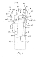
Fig. 2 bis 5 wird der Sortierförderer 22 genauer beschrieben. GemäßFig. 2 und3 umfasst der Sortierförderer 22 mehrere nebeneinander angeordnete Fördereinrichtungen, welche hier als Bandförderer 27 ausgebildet sind. Der Antrieb der Bandförderer 27 erfolgt über eine gemeinsame Antriebswelle 29. - Unter weiterer Bezugnahme auf
Fig. 4 und5 umfasst jeder Bandförderer 27 eine Tragstuktur in Form eines Wippentisches 31, an welchem eine Umlenkrolle 33 drehbar gelagert ist. Ein Förderband 34 läuft um die Umlenkrolle 33 sowie um die Antriebswelle 29 um. Der Wippentisch 31 trägt nicht nur die Umlenkrolle 33, sondern dient auch zum Führen und/oder Stützen des Förderbands 34. Anstelle des Förderbands 34 könnte auch eine Anordnung von mehreren parallel umlaufenden Förderriemen vorgesehen sein. - In einem bestimmten Abstand von der Antriebswelle 29 ist ein parallel zu dieser angeordneter starrer Stützstab 35 vorgesehen, welcher unverdrehbar an einem Gehäuse 39 des Sortierförderers 22 angebracht ist. Jeder Wippentisch 31 ist mittels einer Gelenkarmanordnung 37 verschwenkbar an dem Stützstab 35 gelagert. Zwischen den Wippentischen 31 und der Antriebswelle 29 besteht hingegen keine mechanische Stützverbindung, sondern lediglich die antriebswirksame Verbindung über das umlaufende Förderband 34.
- Jede Gelenkarmanordnung 37 umfasst eine Parallelkinematik mit zwei Parallelhebeln 43, die an voneinander beabstandeten Anlenkpunkten 42 gelenkig mit dem Wippentisch 31 verbunden sind. An den den Anlenkpunkten 42 entgegengesetzten Hebelenden sind die Parallelhebel 43 an einem Koppelhebel 45 angelenkt. Der Koppelhebel 45 erstreckt sich parallel zu der Verbindungslinie der Anlenkpunkte 42 und ist um eine Schwenkachse A2 verschwenkbar in dem Gehäuse 39 gelagert. Weiterhin ist ein Versatzhebel 47 vorgesehen, welcher einerseits an einem der Parallelhebel 43 angelenkt ist und andererseits um eine Schwenkachse A1 verschwenkbar an dem Stützstab 35 gelagert ist. Die Länge des Versatzhebels 47 entspricht dabei der Länge des über den hinteren Anlenkpunkt des Parallelhebels 43 hinausragenden Abschnitts des Koppelhebels 45, so dass die Drehachse R der Antriebswelle 29, die Schwenkachse A2 des Koppelhebels 45 sowie die Schwenkachse A1 des Versatzhebels 27, welche mit der Längsachse L des Stützstabs 35 zusammenfällt, in einer gemeinsamen Ebene E liegen.
- Ein Bewegen der Gelenkarmanordnung 37, beispielsweise durch Verschwenken des Koppelhebels 45, durch Verschwenken des Versatzhebels 47 oder durch lineares Verschieben einer der beiden Parallelhebel 43, bewirkt ein Verschwenken des Wippentischs 31 um die Rotationsachse R der Antriebswelle 29, welche somit eine virtuelle Schwenkachse des Wippentischs 31 bildet. Durch Verschwenken der Wippentische 31 können die Produktportionen 19 einem von mehreren Ausgabebereichen 24A, 24B, 24C der Puffereinrichtung 23 zugeführt werden, welche in
Fig. 4 und5 vereinfacht als übereinander angeordnete Bandförderer dargestellt sind. Ein Antrieb zum Bewegen der Gelenkarmanordnung 37 kann dabei an beliebiger Stelle der sich zwischen dem Stützstab 35 und dem Wippentisch 31 erstreckenden kinematischen Kette erfolgen. Vorzugsweise ist jeder Gelenkarmanordnung 37 ein eigener Antrieb zugeordnet, wobei die Antriebe unabhängig voneinander betreibbar sind, um so während des Förderns der Produktportionen 19 bei jedem der Bandförderer ein individuelles Wechseln des Ausgabebereichs 24A, 24B, 24C vornehmen zu können. Je nach Ausgabebereich 24A, 24B, 24C werden die Produktportionen 19 entweder der Verpackungseinrichtung 25 (Fig. 1 ) oder z.B. einem nicht dargestellten Sammelbehälter für fehlgewichtige Portionen zugeführt. - Da die einzige mechanische Verbindung zwischen dem Wippentisch 31 und der Antriebswelle 29 das umlaufende Förderband 34 ist, kann die Antriebswelle 29 relativ einfach gestaltet sein. Insbesondere kann auf aufwendige Wälzlager und Dichtungen verzichtet werden, welche zum Abstützen der Wippentische 31 an der mit relativ hoher Drehzahl rotierenden Antriebswelle 29 erforderlich wären. Die Schwenkverbindung zwischen dem Versatzhebel 47 und dem starren Stützstab 35 kann mittels einfacher und robuster Gleitlager bewerkstelligt werden. Somit kann eine Produktfördervorrichtung mit mehreren nebeneinander angeordneten und unabhängig voneinander verkippbaren Wippentischen 31 auf einfache Weise hergestellt werden, ohne das Konzept der gemeinsamen Antriebswelle 29 aufgeben zu müssen. Weiterhin ist die Reinigung des Sortierförderers 22 erleichtert. Aufgrund der fehlenden Wälzlager einschließlich der zugehörigen Lagersitze und Dichtungen ist zudem eine effektivere Montage und ein leichterer Service möglich.
-
- 11
- Produktionslinie
- 13
- Hochleistungsslicer
- 14
- Produktzuführung
- 15
- Förderlinie
- 17
- Produkt
- 18
- Produktscheibe
- 19
- Produktportion
- 21
- Eingangsförderer
- 22
- Sortierförderer
- 23
- Puffereinrichtung
- 24A, 24B, 24C
- Ausgabebereich
- 25
- Verpackungseinrichtung
- 27
- Bandförderer
- 29
- Antriebswelle
- 31
- Wippentisch
- 33
- Umlenkrolle
- 34
- Förderband
- 35
- Stützstab
- 37
- Gelenkarmanordnung
- 39
- Gehäuse
- 42
- Anlenkpunkt
- 43
- Parallelhebel
- 45
- Koppelhebel
- 47
- Versatzhebel
- S
- Schneidebene
- P
- Produktförderrichtung
- R
- Drehachse der Antriebswelle
- A1
- Schwenkachse des Versatzhebels
- A2
- Schwenkachse des Koppelhebels
- L
- Längsachse
- E
- gemeinsame Ebene
Claims (15)
- Vorrichtung (22) zum Fördern von Produkten (19), insbesondere Lebensmittelprodukten, mit
wenigstens einer Fördereinrichtung (27), die durch eine Antriebswelle (29) antreibbar ist, um die Produkte (19) jeweils einem von mehreren Ausgabebereichen (24A, 24B, 24C) zuzuführen,
wobei die Fördereinrichtung (27) eine Tragstruktur (31) aufweist, welche zum individuellen Wechseln des Ausgabebereichs (24A, 24B, 24C) um eine Drehachse (R) der Antriebswelle (29) verschwenkbar ist,
dadurchgekennzeichnet, dass
die Tragstruktur (31) derart mittels einer Gelenkarmanordnung (37) an einem von der Antriebswelle (29) beabstandeten Stützelement (35) beweglich gelagert ist, dass durch Bewegen der Gelenkarmanordnung (37) die Tragstruktur (31) um die Drehachse (R) der Antriebswelle (29) verschwenkbar ist. - Vorrichtung nach Anspruch 1,
dadurch gekennzeichnet, dass
zwischen der Tragstruktur (31) und der Antriebswelle (29) keine Stützverbindung besteht. - Vorrichtung nach Anspruch 1 oder 2,
dadurch gekennzeichnet, dass
das Stützelement (35) parallel zu der Antriebswelle (29) verläuft. - Vorrichtung nach zumindest einem der vorstehenden Ansprüche, dadurch gekennzeichnet, dass
mehrere nebeneinander angeordnete Fördereinrichtungen (27) vorgesehen sind, welche durch eine gemeinsame Antriebswelle (29) antreibbar sind und welche jeweilige Tragstrukturen (31) aufweisen, die unabhängig voneinander um die Drehachse (R) der Antriebswelle (29) verschwenkbar sind, wobei jede Tragstruktur (31) mittels einer eigenen Gelenkarmanordnung (37) an dem Stützelement (35) gelagert ist. - Vorrichtung nach Anspruch 4,
dadurch gekennzeichnet, dass
jeder Gelenkarmanordnung (37) ein Antrieb zugeordnet ist, wobei die Antriebe unabhängig voneinander betreibbar sind. - Vorrichtung nach zumindest einem der vorstehenden Ansprüche, dadurch gekennzeichnet, dass
die oder jede Fördereinrichtung (27) als Band- oder Riemenförderer ausgebildet ist, wobei insbesondere ein Förderband (34) oder eine Förderriemenanordnung um die Antriebswelle (29) und um eine an der jeweiligen Tragstruktur (31) gelagerte Umlenkrolle (33) umläuft. - Vorrichtung nach zumindest einem der vorstehenden Ansprüche, dadurch gekennzeichnet, dass
die oder jede Tragstruktur (31) einen Schwenktisch mit einer oder mehreren Führungs- oder Stützflächen für das Förderband (34) oder die Förderriemenanordnung umfasst. - Vorrichtung nach zumindest einem der vorstehenden Ansprüche, dadurch gekennzeichnet, dass
die oder jede Gelenkarmanordnung (37) ein Viergelenk umfasst, wobei das Stützelement (35) einen Fixpunkt des Viergelenks bildet. - Vorrichtung nach zumindest einem der vorstehenden Ansprüche, dadurch gekennzeichnet, dass
die oder jede Gelenkarmanordnung (37) eine Parallelkinematik mit zwei an voneinander beabstandeten Anlenkpunkten (42) mit der Tragstruktur (31) gelenkig verbundenen, vorzugsweise gleich langen, Parallelhebeln (43) umfasst. - Vorrichtung nach Anspruch 9,
dadurch gekennzeichnet, dass
einer der Parallelhebel (43) über einen Versatzhebel (47) beweglich an dem Stützelement (35) gelagert ist. - Vorrichtung nach Anspruch 9 oder 10,
dadurch gekennzeichnet, dass
die beiden Parallelhebel (43) mit einem zu einer Verbindungslinie der Tragstruktur-Anlenkpunkte (42) parallelen Koppelhebel (45) gelenkig verbunden sind. - Vorrichtung nach Anspruch 11,
dadurch gekennzeichnet, dass
die Drehachse (R) der Antriebswelle (29), eine Schwenkachse (A1) des Versatzhebels (47) und eine Schwenkachse (A2) des Koppelhebels (45) in einer gemeinsamen Ebene (E) liegen. - Förderlinie (15), die umfasst:wenigstens einen Eingangsförderer (21),zumindest eine Vorrichtung (22) zum Fördern von Produkten (19) gemäß einem der vorstehenden Ansprüche, undwenigstens eine Aufnahme- oder Puffereinrichtung (23) mit mehreren Ausgabebereichen (24A, 24B, 24C) zum Empfangen der geförderten Produkte (19).
- Produktionslinie (11), die umfasst:wenigstens eine Schneidvorrichtung (13) zum Aufschneiden von Produkten (17), insbesondere Hochleistungs-Slicer, undzumindest eine Förderlinie (15) nach Anspruch 13.
- Produktionslinie nach Anspruch 14,
dadurch gekennzeichnet, dass
der Förderlinie (15) eine Verpackungseinrichtung (25) nachgeordnet ist, welche insbesondere eine Robotereinheit und/oder eine Verpackungsmaschine umfasst.
Applications Claiming Priority (1)
| Application Number | Priority Date | Filing Date | Title |
|---|---|---|---|
| DE102011017420A DE102011017420A1 (de) | 2011-04-18 | 2011-04-18 | Vorrichtung zum Fördern von Produkten |
Publications (2)
| Publication Number | Publication Date |
|---|---|
| EP2514695A1 true EP2514695A1 (de) | 2012-10-24 |
| EP2514695B1 EP2514695B1 (de) | 2016-05-18 |
Family
ID=46022094
Family Applications (1)
| Application Number | Title | Priority Date | Filing Date |
|---|---|---|---|
| EP12164270.6A Not-in-force EP2514695B1 (de) | 2011-04-18 | 2012-04-16 | Vorrichtung zum fördern von produkten, Förderlinie und Produktionslinie mit solcher Vorrichtung |
Country Status (3)
| Country | Link |
|---|---|
| US (1) | US8770378B2 (de) |
| EP (1) | EP2514695B1 (de) |
| DE (1) | DE102011017420A1 (de) |
Cited By (1)
| Publication number | Priority date | Publication date | Assignee | Title |
|---|---|---|---|---|
| DE102016107776A1 (de) * | 2016-04-27 | 2017-11-02 | Weber Maschinenbau Gmbh Breidenbach | Vorrichtung und Verfahren zum Bilden von Portionen |
Families Citing this family (14)
| Publication number | Priority date | Publication date | Assignee | Title |
|---|---|---|---|---|
| DE102013206510A1 (de) | 2012-12-03 | 2014-06-05 | Textor Maschinenbau GmbH | Hochleistungsaufschnittschneidemaschine mit zumindest einer entnehmbaren Bandkassette |
| DE102014202087A1 (de) * | 2014-02-05 | 2015-08-06 | Loesch Verpackungstechnik Gmbh | Vorrichtung und Verfahren zum Aufteilen eines Stroms stückiger Produkte |
| US9770840B2 (en) * | 2015-05-07 | 2017-09-26 | Eric J Wangler | Washable stacker apparatus with self-tensioning feature for use with a food slicing machine |
| US9962849B2 (en) | 2015-05-07 | 2018-05-08 | Eric J Wangler | Washable stacker apparatus with self-tensioning feature for use with a food slicing machine |
| DE102019127189B4 (de) * | 2019-10-09 | 2021-10-14 | Wipotec Gmbh | Sortiervorrichtung |
| CN110686253B (zh) * | 2019-10-10 | 2023-11-28 | 中城绿建科技有限公司 | 裂解气化炉进料装置及其进料方法 |
| DE102020131570A1 (de) | 2020-11-27 | 2022-06-02 | Wipotec Gmbh | Sortierer |
| CN112811141B (zh) * | 2021-01-13 | 2022-11-04 | 合肥中递科技有限公司 | 一种人工智能用多功能物流分拣设备 |
| DE102021105104A1 (de) | 2021-03-03 | 2022-09-08 | Provisur Technologies, Inc. | Bandförderer zum Fördern von Nahrungsmittelprodukten |
| DE102021105105A1 (de) * | 2021-03-03 | 2022-09-08 | Provisur Technologies, Inc. | Förderanlage zum Fördern von Fördergut |
| DE102021105098A1 (de) | 2021-03-03 | 2022-09-08 | Provisur Technologies, Inc. | Nahrungsmittelverarbeitungsanlage |
| US20230126530A1 (en) * | 2021-10-25 | 2023-04-27 | Provisur Technologies, Inc. | Food product gripping assembly for a food product slicing apparatus |
| CN115947117B (zh) * | 2022-12-15 | 2024-01-30 | 宿迁市通用玻璃有限公司 | 一种弧形玻璃加工用的车间运输设备 |
| WO2025061425A1 (de) * | 2023-09-20 | 2025-03-27 | Gea Food Solutions Germany Gmbh | Vorrichtung zum fördern von produkten |
Citations (7)
| Publication number | Priority date | Publication date | Assignee | Title |
|---|---|---|---|---|
| GB820731A (en) * | 1955-11-18 | 1959-09-23 | T & T Vicars Ltd | Improvements in or relating to conveyor systems |
| EP0030653A2 (de) * | 1979-12-03 | 1981-06-24 | Curt George Joa | Apparat zum Wechseln der gefalteten und offenen Kanten einer Folge gefalteter Kissen |
| GB2320235A (en) * | 1996-12-13 | 1998-06-17 | Vanderlande Ind Nederland | Conveying plant |
| EP0879774A1 (de) * | 1997-05-22 | 1998-11-25 | Hogenkamp Verpackungstechnik Wilhelm | Übergabevorrichtung für auf einem umlaufenden endlosen Zuführband in Querreihen ankommende Gegenstände |
| US20020166752A1 (en) * | 2001-05-11 | 2002-11-14 | Ishida Co., Ltd. | Product sorter with transport conveyor |
| EP1666390A1 (de) * | 2004-12-06 | 2006-06-07 | ALPMA Alpenland Maschinenbau GmbH | Zwischenspeicher |
| DE102009039826A1 (de) * | 2009-09-02 | 2011-03-03 | Dipl.-Ing. Schindler & Wagner Gmbh & Co. Kg | Verfahren zum Sortieren von aus Produktlaiben erzeugten Produkten, Sortiervorrichtung hierfür und Schneidmaschine |
Family Cites Families (4)
| Publication number | Priority date | Publication date | Assignee | Title |
|---|---|---|---|---|
| US4809842A (en) * | 1985-09-04 | 1989-03-07 | Nabisco Brands, Inc. | Selective ejection conveyor |
| IT1276144B1 (it) * | 1995-11-16 | 1997-10-27 | Cml Handling Technology S P A | Apparecchio e metodo per caricare oggetti su una smistatrice con piani di trasporto su due livelli |
| EP1261538A1 (de) * | 2000-03-09 | 2002-12-04 | Siemens Production and Logistics Systems AG | Fördereinrichtung zum transport und ausschleusen von fördergut |
| DK1360127T3 (da) * | 2001-02-02 | 2004-11-01 | Siemens Ag | Vertikalomledeindretning |
-
2011
- 2011-04-18 DE DE102011017420A patent/DE102011017420A1/de not_active Withdrawn
-
2012
- 2012-04-16 EP EP12164270.6A patent/EP2514695B1/de not_active Not-in-force
- 2012-04-17 US US13/448,824 patent/US8770378B2/en not_active Expired - Fee Related
Patent Citations (7)
| Publication number | Priority date | Publication date | Assignee | Title |
|---|---|---|---|---|
| GB820731A (en) * | 1955-11-18 | 1959-09-23 | T & T Vicars Ltd | Improvements in or relating to conveyor systems |
| EP0030653A2 (de) * | 1979-12-03 | 1981-06-24 | Curt George Joa | Apparat zum Wechseln der gefalteten und offenen Kanten einer Folge gefalteter Kissen |
| GB2320235A (en) * | 1996-12-13 | 1998-06-17 | Vanderlande Ind Nederland | Conveying plant |
| EP0879774A1 (de) * | 1997-05-22 | 1998-11-25 | Hogenkamp Verpackungstechnik Wilhelm | Übergabevorrichtung für auf einem umlaufenden endlosen Zuführband in Querreihen ankommende Gegenstände |
| US20020166752A1 (en) * | 2001-05-11 | 2002-11-14 | Ishida Co., Ltd. | Product sorter with transport conveyor |
| EP1666390A1 (de) * | 2004-12-06 | 2006-06-07 | ALPMA Alpenland Maschinenbau GmbH | Zwischenspeicher |
| DE102009039826A1 (de) * | 2009-09-02 | 2011-03-03 | Dipl.-Ing. Schindler & Wagner Gmbh & Co. Kg | Verfahren zum Sortieren von aus Produktlaiben erzeugten Produkten, Sortiervorrichtung hierfür und Schneidmaschine |
Cited By (1)
| Publication number | Priority date | Publication date | Assignee | Title |
|---|---|---|---|---|
| DE102016107776A1 (de) * | 2016-04-27 | 2017-11-02 | Weber Maschinenbau Gmbh Breidenbach | Vorrichtung und Verfahren zum Bilden von Portionen |
Also Published As
| Publication number | Publication date |
|---|---|
| EP2514695B1 (de) | 2016-05-18 |
| US20130153364A1 (en) | 2013-06-20 |
| US8770378B2 (en) | 2014-07-08 |
| DE102011017420A1 (de) | 2012-10-18 |
Similar Documents
| Publication | Publication Date | Title |
|---|---|---|
| EP2514695B1 (de) | Vorrichtung zum fördern von produkten, Förderlinie und Produktionslinie mit solcher Vorrichtung | |
| EP3406129B1 (de) | Schneidwerk | |
| EP2364936B1 (de) | Vorrichtung und Verfahren zum Verteilen von Artikeln innerhalb eines Artikelstroms | |
| EP2796255B1 (de) | Vorrichtung zum Fördern von Lebensmittelprodukten | |
| EP2522474B1 (de) | Schneidemaschine | |
| EP2792622B1 (de) | Verfahren und Vorrichtung zum Umorientieren einer Scheibe oder einer Portion eines aufgeschnittenen Lebensmittelprodukts | |
| DE102014117392A1 (de) | Fördervorrichtung | |
| DE102019100631B3 (de) | Sortierer | |
| DE102016107776A1 (de) | Vorrichtung und Verfahren zum Bilden von Portionen | |
| DE102013207401A1 (de) | Vorrichtung und Verfahren zum Aufschneiden von Lebensmittelprodukten | |
| EP4112509A1 (de) | Bandförderer für portionierte lebensmittelprodukte | |
| EP0739834A2 (de) | Vorrichtung zum Verdrehen von in einem Förderprozess befindlichen Produkten | |
| DE102013100806B4 (de) | Mehrspurige Fördervorrichtung | |
| EP3805133B1 (de) | Sortiervorrichtung | |
| EP3722057B1 (de) | Aufschneiden von lebensmittelprodukten | |
| EP3380419B1 (de) | Verfahren und vorrichtung zum portionieren von lebensmittelscheiben mit formveränderung, insbesondere faltung, der portion | |
| EP2583922B1 (de) | Bandanleger mit abklappbarer Vereinzelungsanordnung | |
| DE102016003938B4 (de) | Vorrichtung zum Aufschneiden von Lebensmittelprodukten | |
| EP0899197A2 (de) | Verfahren und Vorrichtung zum Verteilen des Produktstromes | |
| DE102020129751A1 (de) | Aufschneide-Maschine | |
| DE102022113919A1 (de) | Nadelgelagerte Umlenkwalze sowie damit ausgestattete Aufschneide-Maschine | |
| DE102012005598A1 (de) | Vorrichtung zum Fördern von Produkten | |
| DE102021100897A1 (de) | Aufschneide-Maschine | |
| DE3910524A1 (de) | Vorrichtung zum sortieren von stueckgut | |
| DE102006015346A1 (de) | Vorrichtung zum Schneiden von Lebensmittelprodukten |
Legal Events
| Date | Code | Title | Description |
|---|---|---|---|
| PUAI | Public reference made under article 153(3) epc to a published international application that has entered the european phase |
Free format text: ORIGINAL CODE: 0009012 |
|
| AK | Designated contracting states |
Kind code of ref document: A1 Designated state(s): AL AT BE BG CH CY CZ DE DK EE ES FI FR GB GR HR HU IE IS IT LI LT LU LV MC MK MT NL NO PL PT RO RS SE SI SK SM TR |
|
| AX | Request for extension of the european patent |
Extension state: BA ME |
|
| 17P | Request for examination filed |
Effective date: 20130415 |
|
| GRAP | Despatch of communication of intention to grant a patent |
Free format text: ORIGINAL CODE: EPIDOSNIGR1 |
|
| INTG | Intention to grant announced |
Effective date: 20151207 |
|
| GRAS | Grant fee paid |
Free format text: ORIGINAL CODE: EPIDOSNIGR3 |
|
| GRAA | (expected) grant |
Free format text: ORIGINAL CODE: 0009210 |
|
| AK | Designated contracting states |
Kind code of ref document: B1 Designated state(s): AL AT BE BG CH CY CZ DE DK EE ES FI FR GB GR HR HU IE IS IT LI LT LU LV MC MK MT NL NO PL PT RO RS SE SI SK SM TR |
|
| REG | Reference to a national code |
Ref country code: GB Ref legal event code: FG4D Free format text: NOT ENGLISH |
|
| REG | Reference to a national code |
Ref country code: CH Ref legal event code: EP |
|
| REG | Reference to a national code |
Ref country code: IE Ref legal event code: FG4D Free format text: LANGUAGE OF EP DOCUMENT: GERMAN Ref country code: AT Ref legal event code: REF Ref document number: 800248 Country of ref document: AT Kind code of ref document: T Effective date: 20160615 |
|
| REG | Reference to a national code |
Ref country code: DE Ref legal event code: R096 Ref document number: 502012007107 Country of ref document: DE |
|
| REG | Reference to a national code |
Ref country code: NL Ref legal event code: MP Effective date: 20160518 |
|
| REG | Reference to a national code |
Ref country code: LT Ref legal event code: MG4D |
|
| PG25 | Lapsed in a contracting state [announced via postgrant information from national office to epo] |
Ref country code: FI Free format text: LAPSE BECAUSE OF FAILURE TO SUBMIT A TRANSLATION OF THE DESCRIPTION OR TO PAY THE FEE WITHIN THE PRESCRIBED TIME-LIMIT Effective date: 20160518 Ref country code: NO Free format text: LAPSE BECAUSE OF FAILURE TO SUBMIT A TRANSLATION OF THE DESCRIPTION OR TO PAY THE FEE WITHIN THE PRESCRIBED TIME-LIMIT Effective date: 20160818 Ref country code: NL Free format text: LAPSE BECAUSE OF FAILURE TO SUBMIT A TRANSLATION OF THE DESCRIPTION OR TO PAY THE FEE WITHIN THE PRESCRIBED TIME-LIMIT Effective date: 20160518 Ref country code: LT Free format text: LAPSE BECAUSE OF FAILURE TO SUBMIT A TRANSLATION OF THE DESCRIPTION OR TO PAY THE FEE WITHIN THE PRESCRIBED TIME-LIMIT Effective date: 20160518 |
|
| PG25 | Lapsed in a contracting state [announced via postgrant information from national office to epo] |
Ref country code: PT Free format text: LAPSE BECAUSE OF FAILURE TO SUBMIT A TRANSLATION OF THE DESCRIPTION OR TO PAY THE FEE WITHIN THE PRESCRIBED TIME-LIMIT Effective date: 20160919 Ref country code: LV Free format text: LAPSE BECAUSE OF FAILURE TO SUBMIT A TRANSLATION OF THE DESCRIPTION OR TO PAY THE FEE WITHIN THE PRESCRIBED TIME-LIMIT Effective date: 20160518 Ref country code: SE Free format text: LAPSE BECAUSE OF FAILURE TO SUBMIT A TRANSLATION OF THE DESCRIPTION OR TO PAY THE FEE WITHIN THE PRESCRIBED TIME-LIMIT Effective date: 20160518 Ref country code: HR Free format text: LAPSE BECAUSE OF FAILURE TO SUBMIT A TRANSLATION OF THE DESCRIPTION OR TO PAY THE FEE WITHIN THE PRESCRIBED TIME-LIMIT Effective date: 20160518 Ref country code: RS Free format text: LAPSE BECAUSE OF FAILURE TO SUBMIT A TRANSLATION OF THE DESCRIPTION OR TO PAY THE FEE WITHIN THE PRESCRIBED TIME-LIMIT Effective date: 20160518 Ref country code: ES Free format text: LAPSE BECAUSE OF FAILURE TO SUBMIT A TRANSLATION OF THE DESCRIPTION OR TO PAY THE FEE WITHIN THE PRESCRIBED TIME-LIMIT Effective date: 20160518 |
|
| PG25 | Lapsed in a contracting state [announced via postgrant information from national office to epo] |
Ref country code: IT Free format text: LAPSE BECAUSE OF FAILURE TO SUBMIT A TRANSLATION OF THE DESCRIPTION OR TO PAY THE FEE WITHIN THE PRESCRIBED TIME-LIMIT Effective date: 20160518 |
|
| PG25 | Lapsed in a contracting state [announced via postgrant information from national office to epo] |
Ref country code: RO Free format text: LAPSE BECAUSE OF FAILURE TO SUBMIT A TRANSLATION OF THE DESCRIPTION OR TO PAY THE FEE WITHIN THE PRESCRIBED TIME-LIMIT Effective date: 20160518 Ref country code: CZ Free format text: LAPSE BECAUSE OF FAILURE TO SUBMIT A TRANSLATION OF THE DESCRIPTION OR TO PAY THE FEE WITHIN THE PRESCRIBED TIME-LIMIT Effective date: 20160518 Ref country code: SK Free format text: LAPSE BECAUSE OF FAILURE TO SUBMIT A TRANSLATION OF THE DESCRIPTION OR TO PAY THE FEE WITHIN THE PRESCRIBED TIME-LIMIT Effective date: 20160518 Ref country code: DK Free format text: LAPSE BECAUSE OF FAILURE TO SUBMIT A TRANSLATION OF THE DESCRIPTION OR TO PAY THE FEE WITHIN THE PRESCRIBED TIME-LIMIT Effective date: 20160518 Ref country code: EE Free format text: LAPSE BECAUSE OF FAILURE TO SUBMIT A TRANSLATION OF THE DESCRIPTION OR TO PAY THE FEE WITHIN THE PRESCRIBED TIME-LIMIT Effective date: 20160518 |
|
| REG | Reference to a national code |
Ref country code: DE Ref legal event code: R097 Ref document number: 502012007107 Country of ref document: DE |
|
| PG25 | Lapsed in a contracting state [announced via postgrant information from national office to epo] |
Ref country code: PL Free format text: LAPSE BECAUSE OF FAILURE TO SUBMIT A TRANSLATION OF THE DESCRIPTION OR TO PAY THE FEE WITHIN THE PRESCRIBED TIME-LIMIT Effective date: 20160518 Ref country code: SM Free format text: LAPSE BECAUSE OF FAILURE TO SUBMIT A TRANSLATION OF THE DESCRIPTION OR TO PAY THE FEE WITHIN THE PRESCRIBED TIME-LIMIT Effective date: 20160518 |
|
| PLBE | No opposition filed within time limit |
Free format text: ORIGINAL CODE: 0009261 |
|
| STAA | Information on the status of an ep patent application or granted ep patent |
Free format text: STATUS: NO OPPOSITION FILED WITHIN TIME LIMIT |
|
| 26N | No opposition filed |
Effective date: 20170221 |
|
| PG25 | Lapsed in a contracting state [announced via postgrant information from national office to epo] |
Ref country code: SI Free format text: LAPSE BECAUSE OF FAILURE TO SUBMIT A TRANSLATION OF THE DESCRIPTION OR TO PAY THE FEE WITHIN THE PRESCRIBED TIME-LIMIT Effective date: 20160518 |
|
| PG25 | Lapsed in a contracting state [announced via postgrant information from national office to epo] |
Ref country code: MC Free format text: LAPSE BECAUSE OF FAILURE TO SUBMIT A TRANSLATION OF THE DESCRIPTION OR TO PAY THE FEE WITHIN THE PRESCRIBED TIME-LIMIT Effective date: 20160518 |
|
| REG | Reference to a national code |
Ref country code: CH Ref legal event code: PL |
|
| REG | Reference to a national code |
Ref country code: IE Ref legal event code: MM4A |
|
| REG | Reference to a national code |
Ref country code: FR Ref legal event code: ST Effective date: 20171229 |
|
| PG25 | Lapsed in a contracting state [announced via postgrant information from national office to epo] |
Ref country code: FR Free format text: LAPSE BECAUSE OF NON-PAYMENT OF DUE FEES Effective date: 20170502 |
|
| PG25 | Lapsed in a contracting state [announced via postgrant information from national office to epo] |
Ref country code: LI Free format text: LAPSE BECAUSE OF NON-PAYMENT OF DUE FEES Effective date: 20170430 Ref country code: LU Free format text: LAPSE BECAUSE OF NON-PAYMENT OF DUE FEES Effective date: 20170416 Ref country code: CH Free format text: LAPSE BECAUSE OF NON-PAYMENT OF DUE FEES Effective date: 20170430 |
|
| REG | Reference to a national code |
Ref country code: BE Ref legal event code: MM Effective date: 20170430 |
|
| PG25 | Lapsed in a contracting state [announced via postgrant information from national office to epo] |
Ref country code: IE Free format text: LAPSE BECAUSE OF NON-PAYMENT OF DUE FEES Effective date: 20170416 |
|
| PG25 | Lapsed in a contracting state [announced via postgrant information from national office to epo] |
Ref country code: BE Free format text: LAPSE BECAUSE OF NON-PAYMENT OF DUE FEES Effective date: 20170430 |
|
| REG | Reference to a national code |
Ref country code: AT Ref legal event code: MM01 Ref document number: 800248 Country of ref document: AT Kind code of ref document: T Effective date: 20170416 |
|
| PG25 | Lapsed in a contracting state [announced via postgrant information from national office to epo] |
Ref country code: AT Free format text: LAPSE BECAUSE OF NON-PAYMENT OF DUE FEES Effective date: 20170416 |
|
| PG25 | Lapsed in a contracting state [announced via postgrant information from national office to epo] |
Ref country code: MT Free format text: LAPSE BECAUSE OF FAILURE TO SUBMIT A TRANSLATION OF THE DESCRIPTION OR TO PAY THE FEE WITHIN THE PRESCRIBED TIME-LIMIT Effective date: 20160518 |
|
| PG25 | Lapsed in a contracting state [announced via postgrant information from national office to epo] |
Ref country code: AL Free format text: LAPSE BECAUSE OF FAILURE TO SUBMIT A TRANSLATION OF THE DESCRIPTION OR TO PAY THE FEE WITHIN THE PRESCRIBED TIME-LIMIT Effective date: 20160518 |
|
| PG25 | Lapsed in a contracting state [announced via postgrant information from national office to epo] |
Ref country code: HU Free format text: LAPSE BECAUSE OF FAILURE TO SUBMIT A TRANSLATION OF THE DESCRIPTION OR TO PAY THE FEE WITHIN THE PRESCRIBED TIME-LIMIT; INVALID AB INITIO Effective date: 20120416 |
|
| PG25 | Lapsed in a contracting state [announced via postgrant information from national office to epo] |
Ref country code: BG Free format text: LAPSE BECAUSE OF FAILURE TO SUBMIT A TRANSLATION OF THE DESCRIPTION OR TO PAY THE FEE WITHIN THE PRESCRIBED TIME-LIMIT Effective date: 20160518 |
|
| PG25 | Lapsed in a contracting state [announced via postgrant information from national office to epo] |
Ref country code: CY Free format text: LAPSE BECAUSE OF NON-PAYMENT OF DUE FEES Effective date: 20160518 |
|
| PG25 | Lapsed in a contracting state [announced via postgrant information from national office to epo] |
Ref country code: MK Free format text: LAPSE BECAUSE OF FAILURE TO SUBMIT A TRANSLATION OF THE DESCRIPTION OR TO PAY THE FEE WITHIN THE PRESCRIBED TIME-LIMIT Effective date: 20160518 |
|
| PG25 | Lapsed in a contracting state [announced via postgrant information from national office to epo] |
Ref country code: TR Free format text: LAPSE BECAUSE OF FAILURE TO SUBMIT A TRANSLATION OF THE DESCRIPTION OR TO PAY THE FEE WITHIN THE PRESCRIBED TIME-LIMIT Effective date: 20160518 |
|
| PG25 | Lapsed in a contracting state [announced via postgrant information from national office to epo] |
Ref country code: GR Free format text: LAPSE BECAUSE OF FAILURE TO SUBMIT A TRANSLATION OF THE DESCRIPTION OR TO PAY THE FEE WITHIN THE PRESCRIBED TIME-LIMIT Effective date: 20160518 |
|
| PG25 | Lapsed in a contracting state [announced via postgrant information from national office to epo] |
Ref country code: IS Free format text: LAPSE BECAUSE OF FAILURE TO SUBMIT A TRANSLATION OF THE DESCRIPTION OR TO PAY THE FEE WITHIN THE PRESCRIBED TIME-LIMIT Effective date: 20160918 |
|
| PGFP | Annual fee paid to national office [announced via postgrant information from national office to epo] |
Ref country code: GB Payment date: 20200423 Year of fee payment: 9 |
|
| GBPC | Gb: european patent ceased through non-payment of renewal fee |
Effective date: 20210416 |
|
| PG25 | Lapsed in a contracting state [announced via postgrant information from national office to epo] |
Ref country code: GB Free format text: LAPSE BECAUSE OF NON-PAYMENT OF DUE FEES Effective date: 20210416 |
|
| P01 | Opt-out of the competence of the unified patent court (upc) registered |
Effective date: 20230522 |
|
| PGFP | Annual fee paid to national office [announced via postgrant information from national office to epo] |
Ref country code: DE Payment date: 20230418 Year of fee payment: 12 |
|
| REG | Reference to a national code |
Ref country code: DE Ref legal event code: R081 Ref document number: 502012007107 Country of ref document: DE Owner name: WEBER FOOD TECHNOLOGY GMBH, DE Free format text: FORMER OWNER: WEBER MASCHINENBAU GMBH BREIDENBACH, 35236 BREIDENBACH, DE |
|
| REG | Reference to a national code |
Ref country code: DE Ref legal event code: R119 Ref document number: 502012007107 Country of ref document: DE |
|
| PG25 | Lapsed in a contracting state [announced via postgrant information from national office to epo] |
Ref country code: DE Free format text: LAPSE BECAUSE OF NON-PAYMENT OF DUE FEES Effective date: 20241105 |
|
| PG25 | Lapsed in a contracting state [announced via postgrant information from national office to epo] |
Ref country code: DE Free format text: LAPSE BECAUSE OF NON-PAYMENT OF DUE FEES Effective date: 20241105 |