EP2513502B1 - Lagerungseinrichtung für einen antriebsstrang eines kraftwagens - Google Patents
Lagerungseinrichtung für einen antriebsstrang eines kraftwagens Download PDFInfo
- Publication number
- EP2513502B1 EP2513502B1 EP20100754878 EP10754878A EP2513502B1 EP 2513502 B1 EP2513502 B1 EP 2513502B1 EP 20100754878 EP20100754878 EP 20100754878 EP 10754878 A EP10754878 A EP 10754878A EP 2513502 B1 EP2513502 B1 EP 2513502B1
- Authority
- EP
- European Patent Office
- Prior art keywords
- shaft
- bearing
- bearing ring
- mounting device
- inner ring
- Prior art date
- Legal status (The legal status is an assumption and is not a legal conclusion. Google has not performed a legal analysis and makes no representation as to the accuracy of the status listed.)
- Not-in-force
Links
- 238000005096 rolling process Methods 0.000 claims description 10
- 230000036316 preload Effects 0.000 description 22
- 230000008878 coupling Effects 0.000 description 19
- 238000010168 coupling process Methods 0.000 description 19
- 238000005859 coupling reaction Methods 0.000 description 19
- 230000001419 dependent effect Effects 0.000 description 7
- 230000008859 change Effects 0.000 description 4
- 238000006073 displacement reaction Methods 0.000 description 4
- 230000009467 reduction Effects 0.000 description 4
- 230000008901 benefit Effects 0.000 description 3
- 230000005540 biological transmission Effects 0.000 description 3
- 238000002485 combustion reaction Methods 0.000 description 3
- 230000009471 action Effects 0.000 description 2
- 230000015572 biosynthetic process Effects 0.000 description 1
- 230000006835 compression Effects 0.000 description 1
- 238000007906 compression Methods 0.000 description 1
- 238000011161 development Methods 0.000 description 1
- 230000018109 developmental process Effects 0.000 description 1
- 230000000694 effects Effects 0.000 description 1
- 238000005265 energy consumption Methods 0.000 description 1
- 239000000446 fuel Substances 0.000 description 1
- 238000002955 isolation Methods 0.000 description 1
- 230000008092 positive effect Effects 0.000 description 1
- 230000004044 response Effects 0.000 description 1
- 238000009420 retrofitting Methods 0.000 description 1
- 125000006850 spacer group Chemical group 0.000 description 1
Images


Classifications
-
- F—MECHANICAL ENGINEERING; LIGHTING; HEATING; WEAPONS; BLASTING
- F16—ENGINEERING ELEMENTS AND UNITS; GENERAL MEASURES FOR PRODUCING AND MAINTAINING EFFECTIVE FUNCTIONING OF MACHINES OR INSTALLATIONS; THERMAL INSULATION IN GENERAL
- F16C—SHAFTS; FLEXIBLE SHAFTS; ELEMENTS OR CRANKSHAFT MECHANISMS; ROTARY BODIES OTHER THAN GEARING ELEMENTS; BEARINGS
- F16C35/00—Rigid support of bearing units; Housings, e.g. caps, covers
- F16C35/04—Rigid support of bearing units; Housings, e.g. caps, covers in the case of ball or roller bearings
- F16C35/06—Mounting or dismounting of ball or roller bearings; Fixing them onto shaft or in housing
- F16C35/063—Fixing them on the shaft
-
- F—MECHANICAL ENGINEERING; LIGHTING; HEATING; WEAPONS; BLASTING
- F16—ENGINEERING ELEMENTS AND UNITS; GENERAL MEASURES FOR PRODUCING AND MAINTAINING EFFECTIVE FUNCTIONING OF MACHINES OR INSTALLATIONS; THERMAL INSULATION IN GENERAL
- F16C—SHAFTS; FLEXIBLE SHAFTS; ELEMENTS OR CRANKSHAFT MECHANISMS; ROTARY BODIES OTHER THAN GEARING ELEMENTS; BEARINGS
- F16C19/00—Bearings with rolling contact, for exclusively rotary movement
- F16C19/54—Systems consisting of a plurality of bearings with rolling friction
- F16C19/546—Systems with spaced apart rolling bearings including at least one angular contact bearing
- F16C19/547—Systems with spaced apart rolling bearings including at least one angular contact bearing with two angular contact rolling bearings
- F16C19/548—Systems with spaced apart rolling bearings including at least one angular contact bearing with two angular contact rolling bearings in O-arrangement
-
- F—MECHANICAL ENGINEERING; LIGHTING; HEATING; WEAPONS; BLASTING
- F16—ENGINEERING ELEMENTS AND UNITS; GENERAL MEASURES FOR PRODUCING AND MAINTAINING EFFECTIVE FUNCTIONING OF MACHINES OR INSTALLATIONS; THERMAL INSULATION IN GENERAL
- F16C—SHAFTS; FLEXIBLE SHAFTS; ELEMENTS OR CRANKSHAFT MECHANISMS; ROTARY BODIES OTHER THAN GEARING ELEMENTS; BEARINGS
- F16C19/00—Bearings with rolling contact, for exclusively rotary movement
- F16C19/54—Systems consisting of a plurality of bearings with rolling friction
- F16C19/56—Systems consisting of a plurality of bearings with rolling friction in which the rolling bodies of one bearing differ in diameter from those of another
-
- F—MECHANICAL ENGINEERING; LIGHTING; HEATING; WEAPONS; BLASTING
- F16—ENGINEERING ELEMENTS AND UNITS; GENERAL MEASURES FOR PRODUCING AND MAINTAINING EFFECTIVE FUNCTIONING OF MACHINES OR INSTALLATIONS; THERMAL INSULATION IN GENERAL
- F16C—SHAFTS; FLEXIBLE SHAFTS; ELEMENTS OR CRANKSHAFT MECHANISMS; ROTARY BODIES OTHER THAN GEARING ELEMENTS; BEARINGS
- F16C25/00—Bearings for exclusively rotary movement adjustable for wear or play
- F16C25/06—Ball or roller bearings
- F16C25/08—Ball or roller bearings self-adjusting
-
- F—MECHANICAL ENGINEERING; LIGHTING; HEATING; WEAPONS; BLASTING
- F16—ENGINEERING ELEMENTS AND UNITS; GENERAL MEASURES FOR PRODUCING AND MAINTAINING EFFECTIVE FUNCTIONING OF MACHINES OR INSTALLATIONS; THERMAL INSULATION IN GENERAL
- F16H—GEARING
- F16H57/00—General details of gearing
- F16H57/02—Gearboxes; Mounting gearing therein
- F16H57/021—Shaft support structures, e.g. partition walls, bearing eyes, casing walls or covers with bearings
-
- F—MECHANICAL ENGINEERING; LIGHTING; HEATING; WEAPONS; BLASTING
- F16—ENGINEERING ELEMENTS AND UNITS; GENERAL MEASURES FOR PRODUCING AND MAINTAINING EFFECTIVE FUNCTIONING OF MACHINES OR INSTALLATIONS; THERMAL INSULATION IN GENERAL
- F16C—SHAFTS; FLEXIBLE SHAFTS; ELEMENTS OR CRANKSHAFT MECHANISMS; ROTARY BODIES OTHER THAN GEARING ELEMENTS; BEARINGS
- F16C19/00—Bearings with rolling contact, for exclusively rotary movement
- F16C19/22—Bearings with rolling contact, for exclusively rotary movement with bearing rollers essentially of the same size in one or more circular rows, e.g. needle bearings
- F16C19/34—Bearings with rolling contact, for exclusively rotary movement with bearing rollers essentially of the same size in one or more circular rows, e.g. needle bearings for both radial and axial load
- F16C19/36—Bearings with rolling contact, for exclusively rotary movement with bearing rollers essentially of the same size in one or more circular rows, e.g. needle bearings for both radial and axial load with a single row of rollers
- F16C19/364—Bearings with rolling contact, for exclusively rotary movement with bearing rollers essentially of the same size in one or more circular rows, e.g. needle bearings for both radial and axial load with a single row of rollers with tapered rollers, i.e. rollers having essentially the shape of a truncated cone
-
- F—MECHANICAL ENGINEERING; LIGHTING; HEATING; WEAPONS; BLASTING
- F16—ENGINEERING ELEMENTS AND UNITS; GENERAL MEASURES FOR PRODUCING AND MAINTAINING EFFECTIVE FUNCTIONING OF MACHINES OR INSTALLATIONS; THERMAL INSULATION IN GENERAL
- F16C—SHAFTS; FLEXIBLE SHAFTS; ELEMENTS OR CRANKSHAFT MECHANISMS; ROTARY BODIES OTHER THAN GEARING ELEMENTS; BEARINGS
- F16C2361/00—Apparatus or articles in engineering in general
- F16C2361/61—Toothed gear systems, e.g. support of pinion shafts
Definitions
- the invention relates to a storage device for a drive train of a motor vehicle, in particular of a utility vehicle, specified in the preamble of claim 1.
- the DE 10 2005 027 082 A1 discloses a bearing device for motor vehicles, with two rolling bearings whose outer rings are arranged in a housing and whose inner rings on a shaft and a clamping device for axially clamping the outer rings relative to the inner rings.
- the clamping device comprises an intermediate element which allows a change in the axial preload of the rolling bearing by load-dependent change in its thickness dimension.
- the intermediate element is designed, for example, as an electrically controllable piezoelectric element.
- Such actuators and other, for example, mechanical or hydraulic actuators require a control and auxiliary energy, which increases the complexity and thus the cost undesirably.
- An inventive storage device for a drive train of a motor vehicle with at least one shaft, with a rotatably connected to the shaft Drive part, with at least one bearing ring of the shaft and with a clamping device for acting on the bearing ring in the axial direction of the shaft with a force, characterized in that the bearing ring of the shaft by means of the tensioning device as a result of relative rotation of the drive member to the bearing ring with the Force in the axial direction of the shaft can be acted upon, wherein the bearing ring at least partially disposed on the shaft and rotatably connected thereto.
- the shaft of the storage device is driven by the drive part.
- a rotation of a region of the shaft via which this torque is introduced into the shaft takes place relative to a region of the shaft arranged downstream in the direction of this torque flow, in which the bearing ring of the shaft, for example is rotatably connected to the shaft is arranged.
- the bearing ring can now be loaded with the force in the axial direction as a result of this relative rotation of the drive part to the bearing ring, whereby an axial preload of a bearing, which comprises said bearing ring, depending on the amount of applied and introduced into the shaft Torque is enabled.
- the said bearing comprises, for example, not only said bearing ring, which is designed, for example, as rotatably connected to the shaft bearing inner ring, but also a corresponding bearing outer ring, the bearing inner ring and the bearing outer ring are supported by the intermediary of bearing bodies, in particular rolling elements such as tapered rollers against each other , As a result of the action of the bearing ring in the form of the bearing inner ring of the bearing inner ring is thus clamped relative to the bearing outer ring, whereby an axial preload of the bearing is realized in dependence on the amount of the introduced torque.
- the bracing device of the storage device according to the invention thus shown thus requires no to be controlled and energy consuming actuators. Therefore, the storage device according to the invention not only has a low complexity, a low number of parts and the associated low cost but also a low weight, which is the energy consumption of the motor vehicle for operation benefits same. Furthermore, the probability of failure of the storage device according to the invention is classified as extremely low due to the low complexity.
- This torque-dependent bearing preload reduces the power loss of the bearing, especially in low and medium torque ranges, resulting in a further reduction of the energy requirement for the operation of the motor vehicle. For example, if a drive unit designed to drive the motor vehicle as an internal combustion engine, this means a significant fuel reduction and a reduction of CO 2 emissions. In comparison to known storage devices, a reduction of storage losses by up to 30% is possible, which improves the efficiency of the storage device.
- the storage device according to the invention has the advantage that it has only a small space requirement and requires only a minimal change of existing components and thus virtually in existing components almost without time and costly change effort can be integrated. Furthermore, a retrofitting of existing systems with the storage device according to the invention is possible.
- the bracing device at least one control part associated with the drive part and at least partially substantially ramp-shaped and at least one corresponding, the bearing element associated and at least partially substantially ramp-shaped operating part, wherein the control part and the actuating part mediation at least one switching part, in particular a rolling element, act together.
- the drive part with the control part and the bearing ring with the actuating part is integrally formed, which keeps the number of parts and thus the cost of the storage device in a small frame.
- the respective ramp shape is formed, for example, at least substantially parallel to the radial direction.
- the shaft is supported for example by means of at least two bearings, both of which comprise a described, non-rotatably connected to the shaft bearing inner ring and a corresponding bearing outer ring, wherein the bearing outer ring is fixed for example in a housing.
- bearings are, for example, tapered roller bearings, which are arranged in a known X or O arrangement or in any other arrangement.
- the storage device according to the invention is applicable to any type of rolling bearings, which should advantageously transfer backlash axial and radial forces.
- a bearing preload is usually required, which, as described, is achieved by the storage device according to the invention in a simple manner.
- Such a bearing preload causes optimal utilization of the bearing capacity in all operating conditions, avoidance of bearing clearance and a tilting of the shaft and a compensation of thermal expansion.
- the required or desired bearing preload that is to say the magnitude of the force acting in the axial direction of the shaft, is determined experimentally, for example, and is set precisely by spacers.
- the amount of bearing preload is based on the highest occurring load. This causes an additional bearing load and increases the torque-dependent bearing power loss over the entire range of applications.
- control part on a bearing ring facing the end face of the drive part and the actuating part are arranged on a drive part facing the end face of the bearing ring. This allows a targeted and direct power transmission and a low space requirement of the storage device according to the invention.
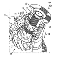
- the Fig. 1 shows a storage device 10 for a drive train of a commercial vehicle with a drive pinion 12 having a shaft 14 which is rotatably connected to a drive member in the form of a coupling flange 16.
- the rotationally fixed connection of the shaft 14 with the coupling flange 16 is realized via a toothing 18, via which a torque of the coupling flange 16 can be transmitted to the shaft 14 during the drive of the utility vehicle of an internal combustion engine, which in turn drives a Schuachsdifferentialgetriebe via its drive pinion 12 ,
- the shaft 14 is mounted in a partially illustrated housing 20 via a first tapered roller bearing 22 and a second tapered roller bearing 24, wherein the Tapered roller bearings 22 and 24 are arranged in an O-arrangement.
- the coupling flange 16 and the tapered roller bearings 22 and 24 are encompassed by a bearing device 10.
- the tapered roller bearing 22 comprises a bearing outer ring 28 which is fixed in rotation in the housing 20, and a rotatably connected to the shaft 14 bearing inner ring 30.
- the bearing outer ring 28 and the bearing inner ring 30 are supported by the intermediary of rolling elements in the form of tapered rollers.
- the tapered roller bearing 22 further includes a cage 32 which holds the tapered rollers in position.
- tapered roller bearing 24 which also includes a bearing outer ring 34 fixed in rotation in the housing 20 and a bearing inner ring 36 rotatably connected to the shaft 14 and rolling elements in the form of tapered rollers and a cage 38.
- the rotationally fixed connection of the bearing inner ring 36 of the tapered roller bearing 24 is realized with the shaft 14 via a toothing 40.
- the toothing 40 is a toothing of the shaft 14 into engagement with a corresponding toothing of a toothed sleeve 42, which rotatably connected to the bearing inner ring 36, for example welded, is. This allows a relative displacement of the bearing inner ring 36 to the shaft 14 in the axial direction of the shaft 14 according to a directional arrow 44.
- a sliding bush 46 is arranged, which reduces the friction in the relative displacement of Bearing inner ring 36 to the shaft 14 is reduced to a minimum and allows the transmission of radial forces of the bearing inner ring 36 on the shaft 14.
- a compression sleeve 48 is also arranged, which is supported on the one hand on the bearing inner ring 30 and on the other hand on the bearing inner ring 36 via corresponding stops.
- a clamping device 50 is provided by means of which due to a relative rotation of the coupling flange 16 to the bearing inner ring 36 of this bearing inner ring 36 in the axial direction of the shaft 14 the directional arrow 44 can be acted upon by force and thus relative to the bearing outer ring 34 is clamped, whereby said bearing preload can be displayed.
- the control part 52 is arranged on a bearing inner ring 36 facing the end face of the coupling flange 16, while the actuating member 54 is disposed on a coupling flange 16 associated end face of the bearing inner ring 36.
- the cylindrical roller 56 relatively ramps on ramped edges of the control member 52 and the actuating member 54 along and thus the control member 52 and the Actuator 54 moves apart.
- control part 52 is supported via the coupling flange 16 in the axial direction of the shaft 14, and also the bearing inner ring 36 is supported via the tapered rollers and the bearing outer ring 34 on a corresponding shoulder 58 of the housing 20 in the axial direction of the shaft 14, it comes to a force in the axial direction of the shaft 14, which results from this tension.
- the amount of this tension and thus the amount of this axial force, which represents the bearing preload, depends on how far the cylindrical roller 56 moves along the corresponding flanks of the ramp-shaped control part 52 and the actuating part 54, which in turn depends on the amount of relative rotation of the Coupling flange 16 to the bearing inner ring 36 depends. This in turn depends on the amount of torque introduced. The higher the torque, the higher the relative movement of the cylindrical roller 56 to the ramped flanks and the higher the bearing preload. This means that very high torques result in very high bearing preloads. Reduces the torque, so also reduces the relative rotation between the coupling flange and the bearing inner ring 36 and thus also the bearing preload.
- the Fig. 2 illustrates this situation again schematically.
- the cylindrical roller 56 extends as well as the respective ramp shape of the control part 52 and the operating part 54 at least substantially parallel to the radial direction of the shaft 14 according to a direction arrow 62.
- a plurality of cylindrical rollers 56 may be provided or provided which held by a corresponding cage in position and in the circumferential direction of the Shaft 14 are arranged distributed.
- Each such cylindrical roller 56 is assigned a corresponding control part 52 or actuating part 54.
- the slope of the flanks of the respective ramp shape determines the amount of force in the axial direction, ie the bearing preload in dependence on the amount of relative rotation of the coupling flange 16 to the bearing inner ring 36.
- a directional arrow 66 in the Fig. 2 indicates the rotation of the shaft 14 and the introduction of said torque via the coupling flange 16 in the shaft 14.
Landscapes
- Engineering & Computer Science (AREA)
- General Engineering & Computer Science (AREA)
- Mechanical Engineering (AREA)
- Support Of The Bearing (AREA)
- Rolling Contact Bearings (AREA)
- Sliding-Contact Bearings (AREA)
- Mounting Of Bearings Or Others (AREA)
- Friction Gearing (AREA)
Applications Claiming Priority (2)
| Application Number | Priority Date | Filing Date | Title |
|---|---|---|---|
| DE102009058560A DE102009058560A1 (de) | 2009-12-17 | 2009-12-17 | Lagerungseinrichtung für einen Antriebsstrang eines Kraftwagens |
| PCT/EP2010/005637 WO2011072760A1 (de) | 2009-12-17 | 2010-09-14 | Lagerungseinrichtung für einen antriebsstrang eines kraftwagens |
Publications (2)
| Publication Number | Publication Date |
|---|---|
| EP2513502A1 EP2513502A1 (de) | 2012-10-24 |
| EP2513502B1 true EP2513502B1 (de) | 2014-04-30 |
Family
ID=43304836
Family Applications (1)
| Application Number | Title | Priority Date | Filing Date |
|---|---|---|---|
| EP20100754878 Not-in-force EP2513502B1 (de) | 2009-12-17 | 2010-09-14 | Lagerungseinrichtung für einen antriebsstrang eines kraftwagens |
Country Status (7)
| Country | Link |
|---|---|
| US (1) | US8888377B2 (https=) |
| EP (1) | EP2513502B1 (https=) |
| JP (1) | JP5592955B2 (https=) |
| CN (1) | CN102656378B (https=) |
| DE (1) | DE102009058560A1 (https=) |
| RU (1) | RU2529112C2 (https=) |
| WO (1) | WO2011072760A1 (https=) |
Families Citing this family (16)
| Publication number | Priority date | Publication date | Assignee | Title |
|---|---|---|---|---|
| DE102013218434B4 (de) * | 2013-08-08 | 2021-03-04 | Magna powertrain gmbh & co kg | Lagerung |
| US9703250B2 (en) * | 2014-03-26 | 2017-07-11 | Kyocera Document Solutions Inc. | Rotating force transmitting mechanism and image forming apparatus |
| JP6394670B2 (ja) * | 2016-10-06 | 2018-09-26 | トヨタ自動車株式会社 | 車両用動力伝達装置 |
| WO2018081795A1 (en) | 2016-10-31 | 2018-05-03 | Zipline Medical, Inc. | Systems and methods for monitoring physical therapy of the knee and other joints |
| CN108374833B (zh) * | 2018-03-05 | 2023-10-03 | 广东工业大学 | 一种刚柔耦合旋转轴承 |
| GB2574074B (en) | 2018-07-27 | 2020-05-20 | Mclaren Applied Tech Ltd | Time synchronisation |
| CN110053357B (zh) * | 2019-05-26 | 2024-04-30 | 上海瑞源印刷设备有限公司 | 一种网纹辊安装结构 |
| GB2588236B (en) | 2019-10-18 | 2024-03-20 | Mclaren Applied Ltd | Gyroscope bias estimation |
| CN111412222B (zh) * | 2020-03-28 | 2022-01-11 | 山东凯美瑞轴承科技有限公司 | 一种新型内外齿轴承以及免于空转的轴承轴 |
| CN111412223A (zh) * | 2020-03-28 | 2020-07-14 | 梅国强 | 一种新型离合器和基于双轴承的动力联动方法 |
| CN111379796B (zh) * | 2020-03-28 | 2022-02-22 | 上海拓泓机械科技有限公司 | 轴承式联轴器和直接电驱动以及发电的轴承和驱动系统 |
| USD1110333S1 (en) | 2021-11-05 | 2026-01-27 | Howmedica Osteonics Corp. | Display screen or portion thereof with animated graphical user interface |
| USD1084008S1 (en) | 2021-11-05 | 2025-07-15 | Howmedica Osteonics Corp. | Display screen or portion thereof with graphical user interface |
| USD1120934S1 (en) | 2021-11-05 | 2026-03-31 | Howmedica Osteonics Corp. | Display screen or portion thereof with graphical user interface |
| USD1053901S1 (en) | 2021-11-05 | 2024-12-10 | Howmedica Osteonics Corp. | Display screen or portion thereof with graphical user interface |
| USD1067239S1 (en) | 2021-11-05 | 2025-03-18 | Howmedica Osteonics Corp. | Display screen or portion thereof with animated graphical user interface |
Family Cites Families (27)
| Publication number | Priority date | Publication date | Assignee | Title |
|---|---|---|---|---|
| US1880660A (en) * | 1927-11-19 | 1932-10-04 | Jeffrey Mfg Co | Journal bearing |
| US2019464A (en) * | 1935-03-28 | 1935-10-29 | Timken Roller Bearing Co | Pinion shaft bearing |
| US2118760A (en) * | 1936-07-03 | 1938-05-24 | Timken Roller Bearing Co | Roller bearing |
| US3066000A (en) * | 1960-08-01 | 1962-11-27 | Int Harvester Co | Bearing mounting |
| JPS462487Y1 (https=) * | 1966-03-05 | 1971-01-28 | ||
| US3516717A (en) * | 1968-11-15 | 1970-06-23 | Gen Motors Corp | Bearing |
| GB1481701A (en) * | 1973-11-02 | 1977-08-03 | Girling Ltd | Thrust devices |
| JPS5338847A (en) * | 1976-09-21 | 1978-04-10 | Ntn Toyo Bearing Co Ltd | Bearing pre-pressure regulating method |
| US4085984A (en) * | 1977-06-30 | 1978-04-25 | The Timken Company | Double row bearing assembly with tapered roller bearings |
| SU1318745A1 (ru) * | 1986-01-06 | 1987-06-23 | Минский Конструкторско-Технологический Экспериментальный Институт Автомобильной Промышленности | Способ создани предварительного нат га в радиально-упорных шариковых и конических роликовых подшипниках при сборке узлов редукторов |
| US4862681A (en) * | 1989-01-19 | 1989-09-05 | Ford New Holland, Inc. | Counterweight for reciprocating conditioning roll |
| US5009523A (en) * | 1989-07-20 | 1991-04-23 | The Timken Company | Double row bearing assembly |
| JP2555492B2 (ja) * | 1991-09-10 | 1996-11-20 | 三菱電機株式会社 | 中間歯車付始動電動機 |
| SE9301501D0 (sv) * | 1993-05-12 | 1993-05-03 | Connecting ring | |
| NL1006545C2 (nl) * | 1997-07-10 | 1999-01-12 | Skf Ind Trading & Dev | Gelijmde lagereenheid voor vrachtwagen. |
| JP2003056662A (ja) * | 2001-08-09 | 2003-02-26 | Nsk Ltd | トロイダル無段変速機 |
| US7086983B2 (en) * | 2001-10-25 | 2006-08-08 | Dana Corporation | Differential with pinion bearings supported on input yoke |
| JP2003172345A (ja) * | 2001-12-07 | 2003-06-20 | Koyo Seiko Co Ltd | 車軸ピニオン用軸受装置および車両用終減速装置 |
| JP2005321004A (ja) * | 2004-05-07 | 2005-11-17 | Nissan Motor Co Ltd | 歯車軸支持構造 |
| DE102004043351A1 (de) * | 2004-09-08 | 2006-03-09 | Fag Kugelfischer Ag & Co. Ohg | Wälzlageranordnung |
| JP2006312973A (ja) * | 2005-05-09 | 2006-11-16 | Nsk Ltd | ローディングカム装置、トロイダル型無段変速機及び摩擦変速機 |
| DE102005027082A1 (de) | 2005-06-11 | 2006-12-14 | Daimlerchrysler Ag | Lagerungsvorrichtung |
| US20080298732A1 (en) * | 2005-12-21 | 2008-12-04 | The Timken Company | Unitized Single Row Bearing with Reverse Thrust Capabilities |
| CN201177538Y (zh) * | 2008-02-22 | 2009-01-07 | 文鉴恒 | 兆瓦级风力发电变桨轴承摩擦力矩数控试验机 |
| US8136997B2 (en) * | 2009-03-24 | 2012-03-20 | American Axle & Manufacturing, Inc. | Multi-piece spacer for setting bearing preload |
| US8439637B2 (en) * | 2009-11-20 | 2013-05-14 | United Technologies Corporation | Bellows preload and centering spring for a fan drive gear system |
| US20120070110A1 (en) * | 2010-09-21 | 2012-03-22 | Owens Steven J | Gearbox assembly component and method |
-
2009
- 2009-12-17 DE DE102009058560A patent/DE102009058560A1/de not_active Withdrawn
-
2010
- 2010-09-14 CN CN201080057067.9A patent/CN102656378B/zh not_active Expired - Fee Related
- 2010-09-14 EP EP20100754878 patent/EP2513502B1/de not_active Not-in-force
- 2010-09-14 RU RU2012129828/11A patent/RU2529112C2/ru not_active IP Right Cessation
- 2010-09-14 JP JP2012543487A patent/JP5592955B2/ja not_active Expired - Fee Related
- 2010-09-14 WO PCT/EP2010/005637 patent/WO2011072760A1/de not_active Ceased
-
2012
- 2012-06-05 US US13/489,104 patent/US8888377B2/en not_active Expired - Fee Related
Also Published As
| Publication number | Publication date |
|---|---|
| JP5592955B2 (ja) | 2014-09-17 |
| RU2012129828A (ru) | 2014-01-27 |
| US8888377B2 (en) | 2014-11-18 |
| RU2529112C2 (ru) | 2014-09-27 |
| CN102656378A (zh) | 2012-09-05 |
| CN102656378B (zh) | 2015-05-13 |
| DE102009058560A1 (de) | 2011-06-22 |
| WO2011072760A1 (de) | 2011-06-23 |
| JP2013514501A (ja) | 2013-04-25 |
| US20120321236A1 (en) | 2012-12-20 |
| EP2513502A1 (de) | 2012-10-24 |
Similar Documents
| Publication | Publication Date | Title |
|---|---|---|
| EP2513502B1 (de) | Lagerungseinrichtung für einen antriebsstrang eines kraftwagens | |
| EP2326853B1 (de) | Betätigungseinrichtung für doppelkupplung | |
| EP2694355B1 (de) | Elektromechanische servolenkung mit spielausgleich für das schneckenradgetriebe | |
| EP2350442B1 (de) | Verstellsystem für nockenwellen einer brennkraftmaschine | |
| DE10161715A1 (de) | Elektrische Hilfskraftlenkung für Kraftfahrzeuge | |
| WO2011104217A1 (de) | Schraubradgetriebe für eine lenkung eines kraftfahrzeugs | |
| DE102012103147A1 (de) | Loslager für ein lenkgetriebe | |
| WO2014170125A1 (de) | Doppelwellfeder mit dämpfender zwischenschicht | |
| DE102013213708A1 (de) | Schneckengetriebe für eine Lenkhilfevorrichtung eines Kraftfahrzeuges mit Spielausgleich | |
| EP2882974B1 (de) | Verschleissausgleichendes betätigungselement für eine kupplung | |
| DE102017128705A1 (de) | Planetenwälzgewindetrieb, Verfahren zur Herstellung eines Planetenwälzgewindetriebes, Aktuator und Ausrücksystem | |
| DE102021213456A1 (de) | Spindelantrieb sowie Verfahren zum Betreiben eines solchen | |
| WO2008068122A1 (de) | Schalttrennkupplung für ein schaltgetriebe | |
| DE102009050121A1 (de) | Untersetzungsgetriebe mit Schnecke und Schneckenrad | |
| DE102019210891A1 (de) | Drehbeschlag mit einer Exzenterbaugruppe | |
| WO2019214835A1 (de) | Kolben-zylinder-system mit getrenntem lager- und dichtbereich | |
| DE102011085489A1 (de) | Spielkompensationseinrichtung sowie spielkompensierendes Axiallager, Motor und elektromotorischer Hilfsantrieb | |
| WO2014009428A1 (de) | Vorrichtung zum andrücken einer zahnstange an ein ritzel | |
| WO2021089218A1 (de) | Kegelreibungskupplung mit einem stellglied und einem hebel zum auskuppeln der kupplung | |
| DE102010050706A1 (de) | Lageranordnung zur Lagerung einer Welle | |
| EP3880499B1 (de) | Kupplungseinrichtung für einen fahrwerksaktuator und fahrwerksaktuator | |
| DE102024117937A1 (de) | Rampenaktor | |
| DE102010026739A1 (de) | Wälzlager mit Montagering und Montage von Wälzlagern | |
| DE102020200827A1 (de) | Lageranordnung in einem Getriebe | |
| DE102022115460A1 (de) | Linearaktuator und Lenksystem |
Legal Events
| Date | Code | Title | Description |
|---|---|---|---|
| PUAI | Public reference made under article 153(3) epc to a published international application that has entered the european phase |
Free format text: ORIGINAL CODE: 0009012 |
|
| 17P | Request for examination filed |
Effective date: 20120523 |
|
| AK | Designated contracting states |
Kind code of ref document: A1 Designated state(s): AL AT BE BG CH CY CZ DE DK EE ES FI FR GB GR HR HU IE IS IT LI LT LU LV MC MK MT NL NO PL PT RO SE SI SK SM TR |
|
| 17Q | First examination report despatched |
Effective date: 20130220 |
|
| DAX | Request for extension of the european patent (deleted) | ||
| GRAP | Despatch of communication of intention to grant a patent |
Free format text: ORIGINAL CODE: EPIDOSNIGR1 |
|
| INTG | Intention to grant announced |
Effective date: 20130913 |
|
| GRAS | Grant fee paid |
Free format text: ORIGINAL CODE: EPIDOSNIGR3 |
|
| GRAA | (expected) grant |
Free format text: ORIGINAL CODE: 0009210 |
|
| AK | Designated contracting states |
Kind code of ref document: B1 Designated state(s): AL AT BE BG CH CY CZ DE DK EE ES FI FR GB GR HR HU IE IS IT LI LT LU LV MC MK MT NL NO PL PT RO SE SI SK SM TR |
|
| REG | Reference to a national code |
Ref country code: GB Ref legal event code: FG4D Free format text: NOT ENGLISH Ref country code: CH Ref legal event code: EP |
|
| REG | Reference to a national code |
Ref country code: AT Ref legal event code: REF Ref document number: 665348 Country of ref document: AT Kind code of ref document: T Effective date: 20140515 |
|
| REG | Reference to a national code |
Ref country code: IE Ref legal event code: FG4D Free format text: LANGUAGE OF EP DOCUMENT: GERMAN |
|
| REG | Reference to a national code |
Ref country code: DE Ref legal event code: R096 Ref document number: 502010006819 Country of ref document: DE Effective date: 20140612 |
|
| REG | Reference to a national code |
Ref country code: SE Ref legal event code: TRGR |
|
| REG | Reference to a national code |
Ref country code: LT Ref legal event code: MG4D |
|
| REG | Reference to a national code |
Ref country code: NL Ref legal event code: VDEP Effective date: 20140430 |
|
| PG25 | Lapsed in a contracting state [announced via postgrant information from national office to epo] |
Ref country code: NO Free format text: LAPSE BECAUSE OF FAILURE TO SUBMIT A TRANSLATION OF THE DESCRIPTION OR TO PAY THE FEE WITHIN THE PRESCRIBED TIME-LIMIT Effective date: 20140730 Ref country code: FI Free format text: LAPSE BECAUSE OF FAILURE TO SUBMIT A TRANSLATION OF THE DESCRIPTION OR TO PAY THE FEE WITHIN THE PRESCRIBED TIME-LIMIT Effective date: 20140430 Ref country code: IS Free format text: LAPSE BECAUSE OF FAILURE TO SUBMIT A TRANSLATION OF THE DESCRIPTION OR TO PAY THE FEE WITHIN THE PRESCRIBED TIME-LIMIT Effective date: 20140830 Ref country code: GR Free format text: LAPSE BECAUSE OF FAILURE TO SUBMIT A TRANSLATION OF THE DESCRIPTION OR TO PAY THE FEE WITHIN THE PRESCRIBED TIME-LIMIT Effective date: 20140731 Ref country code: NL Free format text: LAPSE BECAUSE OF FAILURE TO SUBMIT A TRANSLATION OF THE DESCRIPTION OR TO PAY THE FEE WITHIN THE PRESCRIBED TIME-LIMIT Effective date: 20140430 Ref country code: BG Free format text: LAPSE BECAUSE OF FAILURE TO SUBMIT A TRANSLATION OF THE DESCRIPTION OR TO PAY THE FEE WITHIN THE PRESCRIBED TIME-LIMIT Effective date: 20140730 Ref country code: CY Free format text: LAPSE BECAUSE OF FAILURE TO SUBMIT A TRANSLATION OF THE DESCRIPTION OR TO PAY THE FEE WITHIN THE PRESCRIBED TIME-LIMIT Effective date: 20140430 Ref country code: LT Free format text: LAPSE BECAUSE OF FAILURE TO SUBMIT A TRANSLATION OF THE DESCRIPTION OR TO PAY THE FEE WITHIN THE PRESCRIBED TIME-LIMIT Effective date: 20140430 |
|
| PG25 | Lapsed in a contracting state [announced via postgrant information from national office to epo] |
Ref country code: ES Free format text: LAPSE BECAUSE OF FAILURE TO SUBMIT A TRANSLATION OF THE DESCRIPTION OR TO PAY THE FEE WITHIN THE PRESCRIBED TIME-LIMIT Effective date: 20140430 Ref country code: PL Free format text: LAPSE BECAUSE OF FAILURE TO SUBMIT A TRANSLATION OF THE DESCRIPTION OR TO PAY THE FEE WITHIN THE PRESCRIBED TIME-LIMIT Effective date: 20140430 Ref country code: HR Free format text: LAPSE BECAUSE OF FAILURE TO SUBMIT A TRANSLATION OF THE DESCRIPTION OR TO PAY THE FEE WITHIN THE PRESCRIBED TIME-LIMIT Effective date: 20140430 Ref country code: LV Free format text: LAPSE BECAUSE OF FAILURE TO SUBMIT A TRANSLATION OF THE DESCRIPTION OR TO PAY THE FEE WITHIN THE PRESCRIBED TIME-LIMIT Effective date: 20140430 |
|
| PG25 | Lapsed in a contracting state [announced via postgrant information from national office to epo] |
Ref country code: PT Free format text: LAPSE BECAUSE OF FAILURE TO SUBMIT A TRANSLATION OF THE DESCRIPTION OR TO PAY THE FEE WITHIN THE PRESCRIBED TIME-LIMIT Effective date: 20140901 |
|
| PG25 | Lapsed in a contracting state [announced via postgrant information from national office to epo] |
Ref country code: EE Free format text: LAPSE BECAUSE OF FAILURE TO SUBMIT A TRANSLATION OF THE DESCRIPTION OR TO PAY THE FEE WITHIN THE PRESCRIBED TIME-LIMIT Effective date: 20140430 Ref country code: DK Free format text: LAPSE BECAUSE OF FAILURE TO SUBMIT A TRANSLATION OF THE DESCRIPTION OR TO PAY THE FEE WITHIN THE PRESCRIBED TIME-LIMIT Effective date: 20140430 Ref country code: CZ Free format text: LAPSE BECAUSE OF FAILURE TO SUBMIT A TRANSLATION OF THE DESCRIPTION OR TO PAY THE FEE WITHIN THE PRESCRIBED TIME-LIMIT Effective date: 20140430 Ref country code: RO Free format text: LAPSE BECAUSE OF FAILURE TO SUBMIT A TRANSLATION OF THE DESCRIPTION OR TO PAY THE FEE WITHIN THE PRESCRIBED TIME-LIMIT Effective date: 20140430 Ref country code: SK Free format text: LAPSE BECAUSE OF FAILURE TO SUBMIT A TRANSLATION OF THE DESCRIPTION OR TO PAY THE FEE WITHIN THE PRESCRIBED TIME-LIMIT Effective date: 20140430 |
|
| REG | Reference to a national code |
Ref country code: DE Ref legal event code: R097 Ref document number: 502010006819 Country of ref document: DE |
|
| PLBE | No opposition filed within time limit |
Free format text: ORIGINAL CODE: 0009261 |
|
| STAA | Information on the status of an ep patent application or granted ep patent |
Free format text: STATUS: NO OPPOSITION FILED WITHIN TIME LIMIT |
|
| PG25 | Lapsed in a contracting state [announced via postgrant information from national office to epo] |
Ref country code: IT Free format text: LAPSE BECAUSE OF FAILURE TO SUBMIT A TRANSLATION OF THE DESCRIPTION OR TO PAY THE FEE WITHIN THE PRESCRIBED TIME-LIMIT Effective date: 20140430 |
|
| 26N | No opposition filed |
Effective date: 20150202 |
|
| PG25 | Lapsed in a contracting state [announced via postgrant information from national office to epo] |
Ref country code: MC Free format text: LAPSE BECAUSE OF FAILURE TO SUBMIT A TRANSLATION OF THE DESCRIPTION OR TO PAY THE FEE WITHIN THE PRESCRIBED TIME-LIMIT Effective date: 20140430 Ref country code: LU Free format text: LAPSE BECAUSE OF FAILURE TO SUBMIT A TRANSLATION OF THE DESCRIPTION OR TO PAY THE FEE WITHIN THE PRESCRIBED TIME-LIMIT Effective date: 20140914 |
|
| REG | Reference to a national code |
Ref country code: CH Ref legal event code: PL |
|
| REG | Reference to a national code |
Ref country code: DE Ref legal event code: R097 Ref document number: 502010006819 Country of ref document: DE Effective date: 20150202 |
|
| REG | Reference to a national code |
Ref country code: IE Ref legal event code: MM4A |
|
| PG25 | Lapsed in a contracting state [announced via postgrant information from national office to epo] |
Ref country code: BE Free format text: LAPSE BECAUSE OF NON-PAYMENT OF DUE FEES Effective date: 20140930 |
|
| PG25 | Lapsed in a contracting state [announced via postgrant information from national office to epo] |
Ref country code: CH Free format text: LAPSE BECAUSE OF NON-PAYMENT OF DUE FEES Effective date: 20140930 Ref country code: LI Free format text: LAPSE BECAUSE OF NON-PAYMENT OF DUE FEES Effective date: 20140930 Ref country code: SI Free format text: LAPSE BECAUSE OF FAILURE TO SUBMIT A TRANSLATION OF THE DESCRIPTION OR TO PAY THE FEE WITHIN THE PRESCRIBED TIME-LIMIT Effective date: 20140430 |
|
| PG25 | Lapsed in a contracting state [announced via postgrant information from national office to epo] |
Ref country code: IE Free format text: LAPSE BECAUSE OF NON-PAYMENT OF DUE FEES Effective date: 20140914 |
|
| REG | Reference to a national code |
Ref country code: FR Ref legal event code: PLFP Year of fee payment: 6 |
|
| PG25 | Lapsed in a contracting state [announced via postgrant information from national office to epo] |
Ref country code: SM Free format text: LAPSE BECAUSE OF FAILURE TO SUBMIT A TRANSLATION OF THE DESCRIPTION OR TO PAY THE FEE WITHIN THE PRESCRIBED TIME-LIMIT Effective date: 20140430 |
|
| PG25 | Lapsed in a contracting state [announced via postgrant information from national office to epo] |
Ref country code: MT Free format text: LAPSE BECAUSE OF FAILURE TO SUBMIT A TRANSLATION OF THE DESCRIPTION OR TO PAY THE FEE WITHIN THE PRESCRIBED TIME-LIMIT Effective date: 20140430 |
|
| PG25 | Lapsed in a contracting state [announced via postgrant information from national office to epo] |
Ref country code: HU Free format text: LAPSE BECAUSE OF FAILURE TO SUBMIT A TRANSLATION OF THE DESCRIPTION OR TO PAY THE FEE WITHIN THE PRESCRIBED TIME-LIMIT; INVALID AB INITIO Effective date: 20100914 Ref country code: TR Free format text: LAPSE BECAUSE OF FAILURE TO SUBMIT A TRANSLATION OF THE DESCRIPTION OR TO PAY THE FEE WITHIN THE PRESCRIBED TIME-LIMIT Effective date: 20140430 |
|
| REG | Reference to a national code |
Ref country code: FR Ref legal event code: PLFP Year of fee payment: 7 |
|
| PGFP | Annual fee paid to national office [announced via postgrant information from national office to epo] |
Ref country code: GB Payment date: 20160930 Year of fee payment: 7 |
|
| REG | Reference to a national code |
Ref country code: AT Ref legal event code: MM01 Ref document number: 665348 Country of ref document: AT Kind code of ref document: T Effective date: 20150914 |
|
| PGFP | Annual fee paid to national office [announced via postgrant information from national office to epo] |
Ref country code: FR Payment date: 20160928 Year of fee payment: 7 Ref country code: SE Payment date: 20160926 Year of fee payment: 7 |
|
| PGFP | Annual fee paid to national office [announced via postgrant information from national office to epo] |
Ref country code: DE Payment date: 20161130 Year of fee payment: 7 |
|
| PG25 | Lapsed in a contracting state [announced via postgrant information from national office to epo] |
Ref country code: AT Free format text: LAPSE BECAUSE OF NON-PAYMENT OF DUE FEES Effective date: 20150914 |
|
| REG | Reference to a national code |
Ref country code: DE Ref legal event code: R119 Ref document number: 502010006819 Country of ref document: DE |
|
| REG | Reference to a national code |
Ref country code: SE Ref legal event code: EUG |
|
| GBPC | Gb: european patent ceased through non-payment of renewal fee |
Effective date: 20170914 |
|
| PG25 | Lapsed in a contracting state [announced via postgrant information from national office to epo] |
Ref country code: MK Free format text: LAPSE BECAUSE OF FAILURE TO SUBMIT A TRANSLATION OF THE DESCRIPTION OR TO PAY THE FEE WITHIN THE PRESCRIBED TIME-LIMIT Effective date: 20140430 |
|
| REG | Reference to a national code |
Ref country code: FR Ref legal event code: ST Effective date: 20180531 |
|
| PG25 | Lapsed in a contracting state [announced via postgrant information from national office to epo] |
Ref country code: GB Free format text: LAPSE BECAUSE OF NON-PAYMENT OF DUE FEES Effective date: 20170914 Ref country code: DE Free format text: LAPSE BECAUSE OF NON-PAYMENT OF DUE FEES Effective date: 20180404 |
|
| PG25 | Lapsed in a contracting state [announced via postgrant information from national office to epo] |
Ref country code: FR Free format text: LAPSE BECAUSE OF NON-PAYMENT OF DUE FEES Effective date: 20171002 |
|
| PG25 | Lapsed in a contracting state [announced via postgrant information from national office to epo] |
Ref country code: AL Free format text: LAPSE BECAUSE OF FAILURE TO SUBMIT A TRANSLATION OF THE DESCRIPTION OR TO PAY THE FEE WITHIN THE PRESCRIBED TIME-LIMIT Effective date: 20140430 |
|
| PG25 | Lapsed in a contracting state [announced via postgrant information from national office to epo] |
Ref country code: SE Free format text: LAPSE BECAUSE OF NON-PAYMENT OF DUE FEES Effective date: 20170915 |