EP2513502B1 - Mounting device for a drive train of a motor vehicle - Google Patents
Mounting device for a drive train of a motor vehicle Download PDFInfo
- Publication number
- EP2513502B1 EP2513502B1 EP20100754878 EP10754878A EP2513502B1 EP 2513502 B1 EP2513502 B1 EP 2513502B1 EP 20100754878 EP20100754878 EP 20100754878 EP 10754878 A EP10754878 A EP 10754878A EP 2513502 B1 EP2513502 B1 EP 2513502B1
- Authority
- EP
- European Patent Office
- Prior art keywords
- shaft
- bearing
- bearing ring
- mounting device
- inner ring
- Prior art date
- Legal status (The legal status is an assumption and is not a legal conclusion. Google has not performed a legal analysis and makes no representation as to the accuracy of the status listed.)
- Not-in-force
Links
Images


Classifications
-
- F—MECHANICAL ENGINEERING; LIGHTING; HEATING; WEAPONS; BLASTING
- F16—ENGINEERING ELEMENTS AND UNITS; GENERAL MEASURES FOR PRODUCING AND MAINTAINING EFFECTIVE FUNCTIONING OF MACHINES OR INSTALLATIONS; THERMAL INSULATION IN GENERAL
- F16C—SHAFTS; FLEXIBLE SHAFTS; ELEMENTS OR CRANKSHAFT MECHANISMS; ROTARY BODIES OTHER THAN GEARING ELEMENTS; BEARINGS
- F16C35/00—Rigid support of bearing units; Housings, e.g. caps, covers
- F16C35/04—Rigid support of bearing units; Housings, e.g. caps, covers in the case of ball or roller bearings
- F16C35/06—Mounting or dismounting of ball or roller bearings; Fixing them onto shaft or in housing
- F16C35/063—Fixing them on the shaft
-
- F—MECHANICAL ENGINEERING; LIGHTING; HEATING; WEAPONS; BLASTING
- F16—ENGINEERING ELEMENTS AND UNITS; GENERAL MEASURES FOR PRODUCING AND MAINTAINING EFFECTIVE FUNCTIONING OF MACHINES OR INSTALLATIONS; THERMAL INSULATION IN GENERAL
- F16C—SHAFTS; FLEXIBLE SHAFTS; ELEMENTS OR CRANKSHAFT MECHANISMS; ROTARY BODIES OTHER THAN GEARING ELEMENTS; BEARINGS
- F16C19/00—Bearings with rolling contact, for exclusively rotary movement
- F16C19/54—Systems consisting of a plurality of bearings with rolling friction
- F16C19/546—Systems with spaced apart rolling bearings including at least one angular contact bearing
- F16C19/547—Systems with spaced apart rolling bearings including at least one angular contact bearing with two angular contact rolling bearings
- F16C19/548—Systems with spaced apart rolling bearings including at least one angular contact bearing with two angular contact rolling bearings in O-arrangement
-
- F—MECHANICAL ENGINEERING; LIGHTING; HEATING; WEAPONS; BLASTING
- F16—ENGINEERING ELEMENTS AND UNITS; GENERAL MEASURES FOR PRODUCING AND MAINTAINING EFFECTIVE FUNCTIONING OF MACHINES OR INSTALLATIONS; THERMAL INSULATION IN GENERAL
- F16C—SHAFTS; FLEXIBLE SHAFTS; ELEMENTS OR CRANKSHAFT MECHANISMS; ROTARY BODIES OTHER THAN GEARING ELEMENTS; BEARINGS
- F16C19/00—Bearings with rolling contact, for exclusively rotary movement
- F16C19/54—Systems consisting of a plurality of bearings with rolling friction
- F16C19/56—Systems consisting of a plurality of bearings with rolling friction in which the rolling bodies of one bearing differ in diameter from those of another
-
- F—MECHANICAL ENGINEERING; LIGHTING; HEATING; WEAPONS; BLASTING
- F16—ENGINEERING ELEMENTS AND UNITS; GENERAL MEASURES FOR PRODUCING AND MAINTAINING EFFECTIVE FUNCTIONING OF MACHINES OR INSTALLATIONS; THERMAL INSULATION IN GENERAL
- F16C—SHAFTS; FLEXIBLE SHAFTS; ELEMENTS OR CRANKSHAFT MECHANISMS; ROTARY BODIES OTHER THAN GEARING ELEMENTS; BEARINGS
- F16C25/00—Bearings for exclusively rotary movement adjustable for wear or play
- F16C25/06—Ball or roller bearings
- F16C25/08—Ball or roller bearings self-adjusting
-
- F—MECHANICAL ENGINEERING; LIGHTING; HEATING; WEAPONS; BLASTING
- F16—ENGINEERING ELEMENTS AND UNITS; GENERAL MEASURES FOR PRODUCING AND MAINTAINING EFFECTIVE FUNCTIONING OF MACHINES OR INSTALLATIONS; THERMAL INSULATION IN GENERAL
- F16H—GEARING
- F16H57/00—General details of gearing
- F16H57/02—Gearboxes; Mounting gearing therein
- F16H57/021—Shaft support structures, e.g. partition walls, bearing eyes, casing walls or covers with bearings
-
- F—MECHANICAL ENGINEERING; LIGHTING; HEATING; WEAPONS; BLASTING
- F16—ENGINEERING ELEMENTS AND UNITS; GENERAL MEASURES FOR PRODUCING AND MAINTAINING EFFECTIVE FUNCTIONING OF MACHINES OR INSTALLATIONS; THERMAL INSULATION IN GENERAL
- F16C—SHAFTS; FLEXIBLE SHAFTS; ELEMENTS OR CRANKSHAFT MECHANISMS; ROTARY BODIES OTHER THAN GEARING ELEMENTS; BEARINGS
- F16C19/00—Bearings with rolling contact, for exclusively rotary movement
- F16C19/22—Bearings with rolling contact, for exclusively rotary movement with bearing rollers essentially of the same size in one or more circular rows, e.g. needle bearings
- F16C19/34—Bearings with rolling contact, for exclusively rotary movement with bearing rollers essentially of the same size in one or more circular rows, e.g. needle bearings for both radial and axial load
- F16C19/36—Bearings with rolling contact, for exclusively rotary movement with bearing rollers essentially of the same size in one or more circular rows, e.g. needle bearings for both radial and axial load with a single row of rollers
- F16C19/364—Bearings with rolling contact, for exclusively rotary movement with bearing rollers essentially of the same size in one or more circular rows, e.g. needle bearings for both radial and axial load with a single row of rollers with tapered rollers, i.e. rollers having essentially the shape of a truncated cone
-
- F—MECHANICAL ENGINEERING; LIGHTING; HEATING; WEAPONS; BLASTING
- F16—ENGINEERING ELEMENTS AND UNITS; GENERAL MEASURES FOR PRODUCING AND MAINTAINING EFFECTIVE FUNCTIONING OF MACHINES OR INSTALLATIONS; THERMAL INSULATION IN GENERAL
- F16C—SHAFTS; FLEXIBLE SHAFTS; ELEMENTS OR CRANKSHAFT MECHANISMS; ROTARY BODIES OTHER THAN GEARING ELEMENTS; BEARINGS
- F16C2361/00—Apparatus or articles in engineering in general
- F16C2361/61—Toothed gear systems, e.g. support of pinion shafts
Definitions
- the invention relates to a storage device for a drive train of a motor vehicle, in particular of a utility vehicle, specified in the preamble of claim 1.
- the DE 10 2005 027 082 A1 discloses a bearing device for motor vehicles, with two rolling bearings whose outer rings are arranged in a housing and whose inner rings on a shaft and a clamping device for axially clamping the outer rings relative to the inner rings.
- the clamping device comprises an intermediate element which allows a change in the axial preload of the rolling bearing by load-dependent change in its thickness dimension.
- the intermediate element is designed, for example, as an electrically controllable piezoelectric element.
- Such actuators and other, for example, mechanical or hydraulic actuators require a control and auxiliary energy, which increases the complexity and thus the cost undesirably.
- An inventive storage device for a drive train of a motor vehicle with at least one shaft, with a rotatably connected to the shaft Drive part, with at least one bearing ring of the shaft and with a clamping device for acting on the bearing ring in the axial direction of the shaft with a force, characterized in that the bearing ring of the shaft by means of the tensioning device as a result of relative rotation of the drive member to the bearing ring with the Force in the axial direction of the shaft can be acted upon, wherein the bearing ring at least partially disposed on the shaft and rotatably connected thereto.
- the shaft of the storage device is driven by the drive part.
- a rotation of a region of the shaft via which this torque is introduced into the shaft takes place relative to a region of the shaft arranged downstream in the direction of this torque flow, in which the bearing ring of the shaft, for example is rotatably connected to the shaft is arranged.
- the bearing ring can now be loaded with the force in the axial direction as a result of this relative rotation of the drive part to the bearing ring, whereby an axial preload of a bearing, which comprises said bearing ring, depending on the amount of applied and introduced into the shaft Torque is enabled.
- the said bearing comprises, for example, not only said bearing ring, which is designed, for example, as rotatably connected to the shaft bearing inner ring, but also a corresponding bearing outer ring, the bearing inner ring and the bearing outer ring are supported by the intermediary of bearing bodies, in particular rolling elements such as tapered rollers against each other , As a result of the action of the bearing ring in the form of the bearing inner ring of the bearing inner ring is thus clamped relative to the bearing outer ring, whereby an axial preload of the bearing is realized in dependence on the amount of the introduced torque.
- the bracing device of the storage device according to the invention thus shown thus requires no to be controlled and energy consuming actuators. Therefore, the storage device according to the invention not only has a low complexity, a low number of parts and the associated low cost but also a low weight, which is the energy consumption of the motor vehicle for operation benefits same. Furthermore, the probability of failure of the storage device according to the invention is classified as extremely low due to the low complexity.
- This torque-dependent bearing preload reduces the power loss of the bearing, especially in low and medium torque ranges, resulting in a further reduction of the energy requirement for the operation of the motor vehicle. For example, if a drive unit designed to drive the motor vehicle as an internal combustion engine, this means a significant fuel reduction and a reduction of CO 2 emissions. In comparison to known storage devices, a reduction of storage losses by up to 30% is possible, which improves the efficiency of the storage device.
- the storage device according to the invention has the advantage that it has only a small space requirement and requires only a minimal change of existing components and thus virtually in existing components almost without time and costly change effort can be integrated. Furthermore, a retrofitting of existing systems with the storage device according to the invention is possible.
- the bracing device at least one control part associated with the drive part and at least partially substantially ramp-shaped and at least one corresponding, the bearing element associated and at least partially substantially ramp-shaped operating part, wherein the control part and the actuating part mediation at least one switching part, in particular a rolling element, act together.
- the drive part with the control part and the bearing ring with the actuating part is integrally formed, which keeps the number of parts and thus the cost of the storage device in a small frame.
- the respective ramp shape is formed, for example, at least substantially parallel to the radial direction.
- the shaft is supported for example by means of at least two bearings, both of which comprise a described, non-rotatably connected to the shaft bearing inner ring and a corresponding bearing outer ring, wherein the bearing outer ring is fixed for example in a housing.
- bearings are, for example, tapered roller bearings, which are arranged in a known X or O arrangement or in any other arrangement.
- the storage device according to the invention is applicable to any type of rolling bearings, which should advantageously transfer backlash axial and radial forces.
- a bearing preload is usually required, which, as described, is achieved by the storage device according to the invention in a simple manner.
- Such a bearing preload causes optimal utilization of the bearing capacity in all operating conditions, avoidance of bearing clearance and a tilting of the shaft and a compensation of thermal expansion.
- the required or desired bearing preload that is to say the magnitude of the force acting in the axial direction of the shaft, is determined experimentally, for example, and is set precisely by spacers.
- the amount of bearing preload is based on the highest occurring load. This causes an additional bearing load and increases the torque-dependent bearing power loss over the entire range of applications.
- control part on a bearing ring facing the end face of the drive part and the actuating part are arranged on a drive part facing the end face of the bearing ring. This allows a targeted and direct power transmission and a low space requirement of the storage device according to the invention.
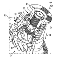
- the Fig. 1 shows a storage device 10 for a drive train of a commercial vehicle with a drive pinion 12 having a shaft 14 which is rotatably connected to a drive member in the form of a coupling flange 16.
- the rotationally fixed connection of the shaft 14 with the coupling flange 16 is realized via a toothing 18, via which a torque of the coupling flange 16 can be transmitted to the shaft 14 during the drive of the utility vehicle of an internal combustion engine, which in turn drives a Schuachsdifferentialgetriebe via its drive pinion 12 ,
- the shaft 14 is mounted in a partially illustrated housing 20 via a first tapered roller bearing 22 and a second tapered roller bearing 24, wherein the Tapered roller bearings 22 and 24 are arranged in an O-arrangement.
- the coupling flange 16 and the tapered roller bearings 22 and 24 are encompassed by a bearing device 10.
- the tapered roller bearing 22 comprises a bearing outer ring 28 which is fixed in rotation in the housing 20, and a rotatably connected to the shaft 14 bearing inner ring 30.
- the bearing outer ring 28 and the bearing inner ring 30 are supported by the intermediary of rolling elements in the form of tapered rollers.
- the tapered roller bearing 22 further includes a cage 32 which holds the tapered rollers in position.
- tapered roller bearing 24 which also includes a bearing outer ring 34 fixed in rotation in the housing 20 and a bearing inner ring 36 rotatably connected to the shaft 14 and rolling elements in the form of tapered rollers and a cage 38.
- the rotationally fixed connection of the bearing inner ring 36 of the tapered roller bearing 24 is realized with the shaft 14 via a toothing 40.
- the toothing 40 is a toothing of the shaft 14 into engagement with a corresponding toothing of a toothed sleeve 42, which rotatably connected to the bearing inner ring 36, for example welded, is. This allows a relative displacement of the bearing inner ring 36 to the shaft 14 in the axial direction of the shaft 14 according to a directional arrow 44.
- a sliding bush 46 is arranged, which reduces the friction in the relative displacement of Bearing inner ring 36 to the shaft 14 is reduced to a minimum and allows the transmission of radial forces of the bearing inner ring 36 on the shaft 14.
- a compression sleeve 48 is also arranged, which is supported on the one hand on the bearing inner ring 30 and on the other hand on the bearing inner ring 36 via corresponding stops.
- a clamping device 50 is provided by means of which due to a relative rotation of the coupling flange 16 to the bearing inner ring 36 of this bearing inner ring 36 in the axial direction of the shaft 14 the directional arrow 44 can be acted upon by force and thus relative to the bearing outer ring 34 is clamped, whereby said bearing preload can be displayed.
- the control part 52 is arranged on a bearing inner ring 36 facing the end face of the coupling flange 16, while the actuating member 54 is disposed on a coupling flange 16 associated end face of the bearing inner ring 36.
- the cylindrical roller 56 relatively ramps on ramped edges of the control member 52 and the actuating member 54 along and thus the control member 52 and the Actuator 54 moves apart.
- control part 52 is supported via the coupling flange 16 in the axial direction of the shaft 14, and also the bearing inner ring 36 is supported via the tapered rollers and the bearing outer ring 34 on a corresponding shoulder 58 of the housing 20 in the axial direction of the shaft 14, it comes to a force in the axial direction of the shaft 14, which results from this tension.
- the amount of this tension and thus the amount of this axial force, which represents the bearing preload, depends on how far the cylindrical roller 56 moves along the corresponding flanks of the ramp-shaped control part 52 and the actuating part 54, which in turn depends on the amount of relative rotation of the Coupling flange 16 to the bearing inner ring 36 depends. This in turn depends on the amount of torque introduced. The higher the torque, the higher the relative movement of the cylindrical roller 56 to the ramped flanks and the higher the bearing preload. This means that very high torques result in very high bearing preloads. Reduces the torque, so also reduces the relative rotation between the coupling flange and the bearing inner ring 36 and thus also the bearing preload.
- the Fig. 2 illustrates this situation again schematically.
- the cylindrical roller 56 extends as well as the respective ramp shape of the control part 52 and the operating part 54 at least substantially parallel to the radial direction of the shaft 14 according to a direction arrow 62.
- a plurality of cylindrical rollers 56 may be provided or provided which held by a corresponding cage in position and in the circumferential direction of the Shaft 14 are arranged distributed.
- Each such cylindrical roller 56 is assigned a corresponding control part 52 or actuating part 54.
- the slope of the flanks of the respective ramp shape determines the amount of force in the axial direction, ie the bearing preload in dependence on the amount of relative rotation of the coupling flange 16 to the bearing inner ring 36.
- a directional arrow 66 in the Fig. 2 indicates the rotation of the shaft 14 and the introduction of said torque via the coupling flange 16 in the shaft 14.
Description
Die Erfindung betrifft eine Lagerungseinrichtung für einen Antriebsstrang eines Kraftwagens, insbesondere eines Nutzkraftwagens, der im Oberbegriff des Patentanspruchs 1 angegebenen Art.The invention relates to a storage device for a drive train of a motor vehicle, in particular of a utility vehicle, specified in the preamble of
Die
Derartige Aktuatoren sowie anderweitige, beispielsweise mechanische oder hydraulische Stellglieder, benötigen eine Regelung sowie Hilfsenergien, was die Komplexität und damit die Kosten unerwünschterweise ansteigen lässt.Such actuators and other, for example, mechanical or hydraulic actuators require a control and auxiliary energy, which increases the complexity and thus the cost undesirably.
Es ist daher Aufgabe der vorliegenden Erfindung, eine Lagerungseinrichtung der eingangs genannten Art bereitzustellen, welche eine geringe Komplexität und geringe Kosten aufweist.It is therefore an object of the present invention to provide a storage device of the type mentioned, which has a low complexity and low cost.
Diese Aufgabe wird durch eine Lagerungseinrichtung für einen Antriebsstrang eines Kraftwagens, insbesondere eines Nutzkraftwagens, mit den Merkmalen des Patentanspruchs 1 gelöst. Vorteilhafte Ausgestaltungen mit zweckmäßigen und nichttrivialen Weiterbildungen der Erfindung sind in den abhängigen Ansprüchen angegeben.This object is achieved by a storage device for a drive train of a motor vehicle, in particular a commercial vehicle, with the features of
Eine erfindungsgemäße Lagerungseinrichtung für einen Antriebsstrang eines Kraftwagens, mit zumindest einer Welle, mit einem mit der Welle drehfest verbundenen Antriebsteil, mit zumindest einem Lagerring der Welle und mit einer Verspanneinrichtung zur Beaufschlagung des Lagerrings in axialer Richtung der Welle mit einer Kraft, zeichnet sich dadurch aus, dass der Lagerring der Welle mittels der Verspanneinrichtung in Folge einer relativen Verdrehung des Antriebsteils zu dem Lagerring mit der Kraft in axialer Richtung der Welle beaufschlagbar ist, wobei der Lagerring zumindest bereichsweise auf der Welle angeordnet und drehfest mit dieser verbunden ist.An inventive storage device for a drive train of a motor vehicle, with at least one shaft, with a rotatably connected to the shaft Drive part, with at least one bearing ring of the shaft and with a clamping device for acting on the bearing ring in the axial direction of the shaft with a force, characterized in that the bearing ring of the shaft by means of the tensioning device as a result of relative rotation of the drive member to the bearing ring with the Force in the axial direction of the shaft can be acted upon, wherein the bearing ring at least partially disposed on the shaft and rotatably connected thereto.
Die Welle der erfindungsgemäßen Lagerungseinrichtung ist dabei von dem Antriebsteil antreibbar. In Abhängigkeit eines von dem Antriebsteil auf die Welle eingeleiteten Drehmoments erfolgt eine Verdrehung eines Bereichs der Welle, über welchen dieses Drehmoment in die Welle eingeleitet wird relativ zu einem in Richtung dieses Momentenflusses stromab angeordneten Bereichs der Welle, in welchem der Lagerring der Welle, der beispielsweise mit der Welle drehfest verbunden ist, angeordnet ist. Mit anderen Worten bedeutet dies, dass sich ein Schaft der Welle in Abhängigkeit von dem Betrag des über das Antriebsteil in die Welle eingeleiteten Drehmoments verdreht, also tordiert. Weiterhin bedeutet dies, dass daraus eine relative Verdrehung des Antriebsteils zu dem Lagerring der Welle resultiert, und zwar ebenso in Abhängigkeit von dem Betrag des eingeleiteten Drehmoments. Mittels der Verspanneinrichtung ist nun in Folge dieser relativen Verdrehung des Antriebsteils zu dem Lagerring der Lagerring mit der Kraft in axialer Richtung beaufschlagbar, wodurch eine axiale Vorspannung eines Lagers, welches den besagten Lagerring umfasst, in Abhängigkeit von dem Betrag des anliegenden und in die Welle eingeleiteten Drehmoments ermöglicht ist.The shaft of the storage device according to the invention is driven by the drive part. As a function of a torque introduced by the drive part onto the shaft, a rotation of a region of the shaft via which this torque is introduced into the shaft takes place relative to a region of the shaft arranged downstream in the direction of this torque flow, in which the bearing ring of the shaft, for example is rotatably connected to the shaft is arranged. In other words, this means that a shaft of the shaft rotates in response to the amount of torque introduced into the shaft via the drive part, that is to say twisted. Furthermore, this means that it results in a relative rotation of the drive member to the bearing ring of the shaft, and also as a function of the amount of torque introduced. By means of the tensioning device, the bearing ring can now be loaded with the force in the axial direction as a result of this relative rotation of the drive part to the bearing ring, whereby an axial preload of a bearing, which comprises said bearing ring, depending on the amount of applied and introduced into the shaft Torque is enabled.
Das besagte Lager umfasst zum Beispiel nicht nur den besagten Lagerring, der beispielsweise als drehfest mit der Welle verbundener Lagerinnenring ausgebildet ist, sondern auch einen korrespondierenden Lageraußenring, wobei der Lagerinnenring und der Lageraußenring unter Vermittlung von Lagerkörpern, insbesondere Wälzkörpern wie beispielsweise Kegelrollen, gegeneinander abgestützt sind. In Folge der Beaufschlagung des Lagerrings in Form des Lagerinnenrings ist somit der Lagerinnenring gegenüber dem Lageraußenring verspannbar, wodurch eine axiale Vorspannung des Lagers in Abhängigkeit von dem Betrag des eingeleiteten Drehmoments realisiert ist.The said bearing comprises, for example, not only said bearing ring, which is designed, for example, as rotatably connected to the shaft bearing inner ring, but also a corresponding bearing outer ring, the bearing inner ring and the bearing outer ring are supported by the intermediary of bearing bodies, in particular rolling elements such as tapered rollers against each other , As a result of the action of the bearing ring in the form of the bearing inner ring of the bearing inner ring is thus clamped relative to the bearing outer ring, whereby an axial preload of the bearing is realized in dependence on the amount of the introduced torque.
Die so dargestellte Verspanneinrichtung der erfindungsgemäßen Lagerungseinrichtung benötigt somit keine zu regelnden und Energie verbrauchenden Stellglieder. Daher weist die erfindungsgemäße Lagerungseinrichtung nicht nur eine geringe Komplexität, eine geringe Teileanzahl und damit einhergehende, niedrige Kosten sondern auch ein niedriges Gewicht auf, was dem Energieverbrauch des Kraftwagens zum Betrieb desselbigen zugute kommt. Des Weiteren ist die Ausfallwahrscheinlichkeit der erfindungsgemäße Lagerungseinrichtung als äußerst niedrig einzustufen aufgrund der geringen Komplexität.The bracing device of the storage device according to the invention thus shown thus requires no to be controlled and energy consuming actuators. Therefore, the storage device according to the invention not only has a low complexity, a low number of parts and the associated low cost but also a low weight, which is the energy consumption of the motor vehicle for operation benefits same. Furthermore, the probability of failure of the storage device according to the invention is classified as extremely low due to the low complexity.
Die beschriebene, relative Verdrehung der Bereiche der Welle erfolgt dabei infolge von Elastizitäten der Welle beziehungsweise ihres Wellenschafts, wobei dieser Effekt zur Darstellung der vorteilhaften axialen Vorspannung des Lagers genutzt wird.The described, relative rotation of the regions of the shaft takes place as a result of elasticities of the shaft or its shaft shaft, this effect being used to illustrate the advantageous axial preload of the bearing.
Diese drehmomentabhängige Lagervorspannung reduziert die Verlustleistung des Lagers insbesondere in niedrigen und mittleren Drehmomentbereichen, woraus eine weitere Reduzierung des Energiebedarfs zum Betrieb des Kraftwagens resultiert. Ist beispielsweise ein Antriebsaggregat zum Antreiben des Kraftwagens als Verbrennungskraftmaschine ausgebildet, so bedeutet dies eine deutliche Kraftstoffreduzierung sowie eine Reduzierung der CO2-Emissionen. Im Vergleich zu bekannten Lagerungseinrichtungen ist dabei eine Reduzierung von Lagerverlustleistungen um bis zu 30% möglich, was den Wirkungsgrad der Lagerungseinrichtung verbessert.This torque-dependent bearing preload reduces the power loss of the bearing, especially in low and medium torque ranges, resulting in a further reduction of the energy requirement for the operation of the motor vehicle. For example, if a drive unit designed to drive the motor vehicle as an internal combustion engine, this means a significant fuel reduction and a reduction of CO 2 emissions. In comparison to known storage devices, a reduction of storage losses by up to 30% is possible, which improves the efficiency of the storage device.
Neben der Tatsache, dass keine zusätzliche Sensoren und/oder Steuergeräte notwendig sind, birgt die erfindungsgemäße Lagerungseinrichtung den Vorteil, dass sie einen nur geringen Bauraumbedarf aufweist sowie eine nur minimale Änderung bereits vorhandener Bauteile erfordert und somit quasi in bereits vorhandene Bauteile nahezu ohne zeit- und kostenaufwändigen Änderungsaufwand integriert werden kann. Des Weiteren ist eine Nachrüstung bereits vorhandener Systeme mit der erfindungsgemäßen Lagerungseinrichtung möglich.In addition to the fact that no additional sensors and / or control units are necessary, the storage device according to the invention has the advantage that it has only a small space requirement and requires only a minimal change of existing components and thus virtually in existing components almost without time and costly change effort can be integrated. Furthermore, a retrofitting of existing systems with the storage device according to the invention is possible.
Bei einer vorteilhaften Ausführungsform der Erfindung weist die Verspanneinrichtung wenigstens ein dem Antriebsteil zugeordnetes und zumindest bereichsweise im Wesentlichen rampenförmiges Steuerteil sowie wenigstens ein korrespondierendes, dem Lagerelement zugeordnetes und zumindest bereichsweise im Wesentlichen rampenförmiges Betätigungsteil auf, wobei das Steuerteil und das Betätigungsteil unter Vermittlung zumindest eines Vermittlungsteils, insbesondere eines Wälzkörpers, zusammen wirken. Vorteilhafterweise ist das Antriebsteil mit dem Steuerteil sowie der Lagerring mit dem Betätigungsteil einstückig ausgebildet, was die Teileanzahl und damit die Kosten der Lagerungseinrichtung in einem geringen Rahmen hält. Die jeweilige Rampenform ist dabei beispielsweise zumindest im Wesentlichen parallel zur radialen Richtung ausgebildet. In jeglicher Hinsicht ist somit die relative Verdrehung der Welle beziehungsweise der Bereiche der Welle und damit die relative Verdrehung des Antriebsteils zu dem Lagerring durch das Steuerteil und das Betätigungsteil umsetzbar in eine axiale Kraftbeaufschlagung des Lagerrings der Welle und damit in eine axiale Bewegung desselbigen, wodurch die drehmomentabhängige und damit bedarfsgerechte Lagervorspannung realisiert ist. Der Wälzkörper, unter dessen Vermittlung das Steuerteil sowie das Betätigungsteil zusammenwirken, ist beispielsweise als Zylinderrolle ausgebildet, wodurch hohe, axiale Kräfte übertragbar sind.In an advantageous embodiment of the invention, the bracing device at least one control part associated with the drive part and at least partially substantially ramp-shaped and at least one corresponding, the bearing element associated and at least partially substantially ramp-shaped operating part, wherein the control part and the actuating part mediation at least one switching part, in particular a rolling element, act together. Advantageously, the drive part with the control part and the bearing ring with the actuating part is integrally formed, which keeps the number of parts and thus the cost of the storage device in a small frame. The respective ramp shape is formed, for example, at least substantially parallel to the radial direction. In all respects, therefore, is the relative rotation of the shaft or the areas of the shaft and thus the relative rotation of the drive member to the bearing ring by the control part and the actuating member implemented in an axial force loading of the bearing ring of the shaft and thus in an axial movement desselbigen, whereby the torque-dependent and thus needs bearing preload is realized. The rolling elements, under the mediation of the control part and the actuating part cooperate, for example, is designed as a cylindrical roller, whereby high, axial forces can be transmitted.
An dieser Stelle sei angemerkt, dass die Welle beispielsweise mittels zumindest zweier Lager gelagert ist, die beide einen beschriebenen, drehfest mit der Welle verbundenen Lagerinnenring sowie einen korrespondierenden Lageraußenring umfassen, wobei der Lageraußenring beispielsweise in einem Gehäuse festgelegt ist. Bei diesen Lagern handelt es sich beispielsweise um Kegelrollenlager, die in einer bekannten X- oder O-Anordnung oder in einer anderweitigen Anordnung angeordnet sind. Die erfindungsgemäße Lagerungseinrichtung ist aber bei jedweder Art von Wälzlagern anwendbar, die vorteilhafterweise spielfrei Axial- und Radialkräfte übertragen sollen. Dazu ist in der Regel eine Lagervorspannung nötig, die, wie beschrieben, durch die erfindungsgemäße Lagerungseinrichtung auf einfache Art und Weise gelöst ist.At this point it should be noted that the shaft is supported for example by means of at least two bearings, both of which comprise a described, non-rotatably connected to the shaft bearing inner ring and a corresponding bearing outer ring, wherein the bearing outer ring is fixed for example in a housing. These bearings are, for example, tapered roller bearings, which are arranged in a known X or O arrangement or in any other arrangement. However, the storage device according to the invention is applicable to any type of rolling bearings, which should advantageously transfer backlash axial and radial forces. For this purpose, a bearing preload is usually required, which, as described, is achieved by the storage device according to the invention in a simple manner.
Eine solche Lagervorspannung bewirkt eine optimale Ausnutzung der Lagertragfähigkeit in allen Betriebszuständen, eine Vermeidung von Lagerspiel und eines Verkippens der Welle sowie eine Kompensation von Wärmeausdehnungen.Such a bearing preload causes optimal utilization of the bearing capacity in all operating conditions, avoidance of bearing clearance and a tilting of the shaft and a compensation of thermal expansion.
Die nötige beziehungsweise gewünschte Lagervorspannung, also der Betrag der in axialer Richtung der Welle wirkenden Kraft, wird beispielsweise experimentell ermittelt und herkömmlich durch Distanzscheiben exakt eingestellt. Dabei orientiert sich der Betrag der Lagervorspannung an der höchsten, auftretenden Belastung. Dies verursacht eine zusätzliche Lagerbelastung und erhöht die drehmomentabhängige Lagerverlustleistung über dem gesamten Einsatzspektrum. Der Einsatz eines Stellglieds, beispielsweise in Form eines Aktuators, zur gezielten, drehmomentabhängigen Lagervorspannung reduziert im Teillastbereich die Vorspannung und verbessert den Wirkungsgrad, weist aber die bereits beschriebenen Nachteile auf.The required or desired bearing preload, that is to say the magnitude of the force acting in the axial direction of the shaft, is determined experimentally, for example, and is set precisely by spacers. The amount of bearing preload is based on the highest occurring load. This causes an additional bearing load and increases the torque-dependent bearing power loss over the entire range of applications. The use of an actuator, for example in the form of an actuator, for targeted, torque-dependent bearing preload reduced in the partial load range, the bias and improves the efficiency, but has the disadvantages already described.
Diese verbleibenden Nachteile eines solchen aktiven Stellglieds sowie die Nachteile der erhöhten Lagerverlustleistungen über dem gesamten Einsatzspektrum sind durch die erfindungsgemäße Lagerungseinrichtung überwunden.These remaining disadvantages of such an active actuator as well as the disadvantages of increased storage losses over the entire range of applications are overcome by the storage device according to the invention.
Vorteilhafterweise sind das Steuerteil auf einer dem Lagerring zugewandten Stirnseite des Antriebsteils und das Betätigungsteil auf einer dem Antriebsteil zugewandten Stirnseite des Lagerrings angeordnet. Dies erlaubt eine gezielte und direkte Kraftübertragung sowie einen geringen Bauraumbedarf der erfindungsgemäßen Lagerungseinrichtung.Advantageously, the control part on a bearing ring facing the end face of the drive part and the actuating part are arranged on a drive part facing the end face of the bearing ring. This allows a targeted and direct power transmission and a low space requirement of the storage device according to the invention.
Weitere Vorteile, Merkmale und Einzelheiten der Erfindung ergeben sich aus der nachfolgenden Beschreibung eines bevorzugten Ausführungsbeispiels sowie anhand der Zeichnungen. Die vorstehend in der Beschreibung genannten Merkmale und Merkmalskombinationen sowie die nachfolgend in der Figurenbeschreibung genannten und/oder in der Figur alleine gezeigten Merkmale und Merkmalskombinationen sind nicht nur in der jeweils angegebenen Kombination, sondern auch in anderen Kombinationen oder in Alleinstellung verwendbar, ohne den Rahmen der Erfindung zu verlassen.Further advantages, features and details of the invention will become apparent from the following description of a preferred embodiment and from the drawings. The features and feature combinations mentioned above in the description as well as the features and feature combinations mentioned below in the figure description and / or shown alone in the figure can be used not only in the respectively specified combination, but also in other combinations or in isolation, without the scope of To leave invention.
Die Zeichnungen zeigen in:
- Fig. 1
- eine perspektivische Ansicht einer Ausführungsform der erfindungsgemäßen Lagerungseinrichtung;
- Fig. 2
- eine schematische Längsschnittansicht der Lagerungseinrichtung gemäß
Fig. 1 ; und - Fig. 3
- zwei schematische Ansichten zur Verdeutlichung des Wirkprinzips der Lagerungseinrichtung gemäß den vorhergehenden Figuren.
- Fig. 1
- a perspective view of an embodiment of the storage device according to the invention;
- Fig. 2
- a schematic longitudinal sectional view of the storage device according to
Fig. 1 ; and - Fig. 3
- two schematic views to illustrate the principle of action of the storage device according to the preceding figures.
Die
Die Welle 14 ist in einem ausschnittsweise dargestellten Gehäuse 20 über ein erstes Kegelrollenlager 22 sowie über ein zweites Kegelrollenlager 24 gelagert, wobei die Kegelrollenlager 22 und 24 in einer O-Anordnung angeordnet sind. Der Kupplungsflansch 16 sowie die Kegelrollenlager 22 und 24 sind dabei von einer Lagerungseinrichtung 10 umfasst.The
Das Kegelrollenlager 22 umfasst einen Lageraußenring 28, der drehfest in dem Gehäuse 20 festgelegt ist, sowie einen mit der Welle 14 drehfest verbundenen Lagerinnenring 30. Der Lageraußenring 28 und der Lagerinnenring 30 sind unter Vermittlung von Wälzkörpern in Form von Kegelrollen aneinander abgestützt. Das Kegelrollenlager 22 umfasst weiterhin einen Käfig 32, der die Kegelrollen in Position hält.The tapered roller bearing 22 comprises a bearing
Analog verhält es sich mit dem Kegelrollenlager 24, welches ebenso einen drehfest in dem Gehäuse 20 festgelegten Lageraußenring 34 sowie einen drehfest mit der Welle 14 verbundenen Lagerinnenring 36 und Wälzkörper in Form von Kegelrollen sowie einen Käfig 38 umfasst.The situation is analogous to the tapered roller bearing 24, which also includes a bearing
Ist der Lagerinnenring 30 des Kegelrollenlagers 22 beispielsweise durch einen Presssitz mit der Welle 14 drehfest verbunden, so ist die drehfeste Verbindung des Lagerinnenrings 36 des Kegelrollenlagers 24 mit der Welle 14 über eine Verzahnung 40 realisiert. Bei der Verzahnung 40 steht eine Verzahnung der Welle 14 in Eingriff mit einer korrespondierenden Verzahnung einer Zahnhülse 42, welche mit dem Lagerinnenring 36 drehfest verbunden, beispielsweise verschweißt, ist. Dies ermöglicht eine relative Verschiebung des Lagerinnenrings 36 zur Welle 14 in axialer Richtung der Welle 14 gemäß einem Richtungspfeil 44. In radialer Richtung der Welle 14 ist zwischen dem Lagerinnenring 36 und der Welle 14 eine Gleitbuchse 46 angeordnet, die die Reibung bei der relativen Verschiebung des Lagerinnenrings 36 zur Welle 14 auf ein Minimum reduziert und die Übertragung von Radialkräften des Lagerinnenrings 36 auf die Welle 14 ermöglicht.Is the bearing
In axialer Richtung der Welle 14 gemäß dem Richtungspfeil 44 zwischen dem Lagerinnenring 30 und dem Lagerinnenring 36 ist außerdem eine Stauchhülse 48 angeordnet, die einerseits an dem Lagerinnenring 30 und andererseits an dem Lagerinnenring 36 über entsprechende Anschläge abgestützt ist.In the axial direction of the
Bei der Lagerungseinrichtung 10 ist eine spielfreie Übertragung von Axialkräften, also von in axialer Richtung der Welle 14 gemäß dem Richtungspfeil 44 wirkenden Kräften, erwünscht, was eine Lagervorspannung der Lagerungseinrichtung 10 beziehungsweise der Kegelrollenlager 22 und 24 in axialer Richtung erfordert.In the
Dabei ist es wünschenswert, bei hohen, von der Verbrennungskraftmaschine zur Verfügung gestellten und über dem Kupplungsflansch 16 in die Welle 14 eingeleiteten Drehmomenten eine hohe Lagervorspannung, also einen hohen Betrag an axialer Kraft, bereitzustellen, während bei niedrigen und mittleren Drehmomenten eine reduzierte Lagervorspannung wünschenswert ist und sich positiv auf den Wirkungsgrad der Lagerungseinrichtung 10 auswirkt.It is desirable at high, provided by the internal combustion engine and introduced over the
Zur Darstellung einer solchen, drehmomentabhängigen Lagervorspannung, also einer Verspannung des Lagerinnenrings 36 zum Lageraußenring 34 des Kegelrollenlagers 24, ist eine Verspanneinrichtung 50 vorgesehen, mittels welcher infolge einer relativen Verdrehung des Kupplungsflansches 16 zu dem Lagerinnenring 36 dieser Lagerinnenring 36 in axialer Richtung der Welle 14 gemäß dem Richtungspfeil 44 mit Kraft beaufschlagbar ist und somit relativ zu dem Lageraußenring 34 verspannbar ist, wodurch die besagte Lagervorspannung darstellbar ist.To illustrate such, torque-dependent bearing preload, so a strain of the bearing
Die relative Verdrehung des drehfest mit der Welle 14 verbundenen Kupplungsflansches 16 zu dem ebenfalls drehfest mit der Welle 14 verbundenen Lagerinnenring 36 erfolgt dabei dadurch, dass sich ein Bereich der Welle 14, in welche das Drehmoment über den Kupplungsflansch 16 eingeleitet wird aufgrund von Elastizitäten der Welle 14 relativ zu einem in Richtung des Momentenflusses stromab angeordneten Bereich der Welle 14 verdreht. Das bedeutet also, dass sich der Bereich der Welle 14, in welchem der Kupplungsflansch 16 mit der Welle verbunden ist, relativ zu dem Bereich, in welchem der Lagerring 36 angeordnet ist, verdreht, wobei diese relative Verdrehung in Abhängigkeit des Betrags des eingeleiteten Drehmoments erfolgt. Bei hohen Drehmomenten erfolgt somit eine hohe relative Verdrehung. Bei niedrigen Drehmomenten erfolgt eine weniger starke bis gar keine relative Verdrehung.The relative rotation of the non-rotatably connected to the
Diese relative Verdrehung um die Drehachse der Welle 14 ist nun derart in eine Bewegung des Lagerinnenrings 36 beziehungsweise in eine Beaufschlagung dieses mit einer Kraft in axialer Richtung der Welle 14 dargestellt, dass die Verspanneinrichtung 50 ein dem Kupplungsflansch 16 zugeordnetes, mit diesem einstückig ausgebildetes und im Wesentlichen rampenförmiges Steuerteil 52 sowie ein korrespondierendes, dem Lagerinnenring 36 zugeordnetes, mit diesem einstückig ausgebildetes sowie ebenfalls im Wesentlichen rampenförmiges Betätigungsteil 54 aufweist, welche unter Vermittlung von jeweiligen Zylinderrollen 56 zusammenwirken.This relative rotation about the axis of rotation of the
Das Steuerteil 52 ist dabei auf einer dem Lagerinnenring 36 zugewandten Stirnseite des Kupplungsflansches 16 angeordnet, während das Betätigungsteil 54 auf einer dem Kupplungsflansch 16 zugeordneten Stirnseite des Lagerinnenrings 36 angeordnet ist. In Zusammenschau mit
Der Betrag dieser Verspannung und damit der Betrag dieser axialen Kraft, welche die Lagervorspannung darstellt, hängt dabei davon ab, wie weit die Zylinderrolle 56 an den entsprechenden Flanken des rampenförmigen Steuerteils 52 beziehungsweise Betätigungsteils 54 entlang wandert, was wiederum von dem Betrag der relativen Verdrehung des Kupplungsflansches 16 zu dem Lagerinnenring 36 abhängt. Dies wiederum hängt ab von dem Betrag des eingeleiteten Drehmoments. Je höher das Drehmoment, desto höher ist die relative Bewegung der Zylinderrolle 56 zu den rampenförmigen Flanken und desto höher ist die Lagervorspannung. Das bedeutet, dass aus sehr hohen Drehmomenten sehr hohe Lagervorspannungen resultieren. Reduziert sich das Drehmoment, so reduziert sich auch die relative Verdrehung zwischen dem Kupplungsflansch und dem Lagerinnenring 36 und somit auch die Lagervorspannung.The amount of this tension and thus the amount of this axial force, which represents the bearing preload, depends on how far the
Die Ausbildung der axialen Kraft, welche durch einen Richtungspfeil 59 angedeutet ist, wobei die relative Verdrehung des Kupplungsflansches 16 zu dem Lagerinnenring 36 durch einen Richtungspfeil 60 angedeutet ist, wird dadurch begünstigt, dass die axiale Verschiebung des Lagerinnenrings 36 relativ zur Welle durch die beschriebene Gleitbuchse 46 begünstigt ist, wodurch die auf den Lagerinnenring 36 aufgebrachte Kraft zumindest nahezu vollständig in die Lagervorspannung fließen kann. Wie erwähnt erlaubt auch die Verzahnung 40 diese relative Verschiebung des Lagerinnenrings 36 zur Welle 14.The formation of the axial force, which is indicated by a directional arrow 59, wherein the relative rotation of the
Die
Claims (9)
- Mounting device (10) for a drive train of a motor vehicle, having at least one shaft (14), a drive part (16) connected to the shaft (14) for rotation therewith, at least one bearing ring (36) of the shaft (14) and a tensioning means (50) for applying a force to the bearing ring (36) in the axial direction (44) of the shaft,
characterised in that
the force can be applied to the bearing ring (36) in the axial direction (44) of the shaft (14) by means of the tensioning means (50) due to a relative rotation of the drive part (16) with respect to the bearing ring (36), wherein the bearing ring (36) is arranged at least partially on the shaft (14) and connected to rotate therewith. - Mounting device (10) according to claim 1,
characterised in that
the tensioning means (50) has at least one control part (52) assigned to the drive part (16) and at least partially at least substantially in the form of a ramp, and at least one corresponding actuating part (54) assigned to the bearing ring (36) and at least partially at least substantially in the form of a ramp, said parts cooperating through the intermediary of an intermediate part (56), in particular a rolling body (56). - Mounting device (10) according to claim 2,
characterised in that
the rolling body (56) is formed as a cylinder roller (56). - Mounting device (10) according to one of the claims 2 or 3,
characterised in that
the control part (52) is arranged on an end face of the drive part (16) facing the bearing ring (36). - Mounting device (10) according to one of the claims 2 to 4,
characterised in that
the actuating part (54) is arranged on an end face of the bearing ring (36) facing the drive part (16). - Mounting device (10) according to one of the claims 2 to 5,
characterised in that
the respective ramp form is configured at least substantially parallel to the radial direction (62) of the shaft (14). - Mounting device (10) according to one of the preceding claims,
characterised in that
the bearing ring (36) is rotatably connected by means of a toothed area (40) to the shaft (14). - Mounting device (10) according to one of the preceding claims,
characterised in that
the bearing ring (36) can be displaced in the axial direction (44) of the shaft (14) relative thereto. - Mounting device (10) according to one of the preceding claims,
characterised in that
a slide element (46), in particular a slide bushing (46), is arranged in the radial direction (62) of the shaft (14) between said shaft (14) and the bearing ring (36).
Applications Claiming Priority (2)
| Application Number | Priority Date | Filing Date | Title |
|---|---|---|---|
| DE102009058560A DE102009058560A1 (en) | 2009-12-17 | 2009-12-17 | Storage device for a drive train of a motor vehicle |
| PCT/EP2010/005637 WO2011072760A1 (en) | 2009-12-17 | 2010-09-14 | Mounting device for a drive train of a motor vehicle |
Publications (2)
| Publication Number | Publication Date |
|---|---|
| EP2513502A1 EP2513502A1 (en) | 2012-10-24 |
| EP2513502B1 true EP2513502B1 (en) | 2014-04-30 |
Family
ID=43304836
Family Applications (1)
| Application Number | Title | Priority Date | Filing Date |
|---|---|---|---|
| EP20100754878 Not-in-force EP2513502B1 (en) | 2009-12-17 | 2010-09-14 | Mounting device for a drive train of a motor vehicle |
Country Status (7)
| Country | Link |
|---|---|
| US (1) | US8888377B2 (en) |
| EP (1) | EP2513502B1 (en) |
| JP (1) | JP5592955B2 (en) |
| CN (1) | CN102656378B (en) |
| DE (1) | DE102009058560A1 (en) |
| RU (1) | RU2529112C2 (en) |
| WO (1) | WO2011072760A1 (en) |
Families Citing this family (10)
| Publication number | Priority date | Publication date | Assignee | Title |
|---|---|---|---|---|
| DE102013218434B4 (en) * | 2013-08-08 | 2021-03-04 | Magna powertrain gmbh & co kg | storage |
| WO2015146271A1 (en) * | 2014-03-26 | 2015-10-01 | 京セラドキュメントソリューションズ株式会社 | Rotational force transmission mechanism and image formation device |
| JP6394670B2 (en) * | 2016-10-06 | 2018-09-26 | トヨタ自動車株式会社 | Power transmission device for vehicle |
| WO2018081795A1 (en) | 2016-10-31 | 2018-05-03 | Zipline Medical, Inc. | Systems and methods for monitoring physical therapy of the knee and other joints |
| CN108374833B (en) * | 2018-03-05 | 2023-10-03 | 广东工业大学 | Rigid-flexible coupling rotary bearing |
| GB2574074B (en) | 2018-07-27 | 2020-05-20 | Mclaren Applied Tech Ltd | Time synchronisation |
| GB2588236B (en) | 2019-10-18 | 2024-03-20 | Mclaren Applied Ltd | Gyroscope bias estimation |
| CN111379796B (en) * | 2020-03-28 | 2022-02-22 | 上海拓泓机械科技有限公司 | Bearing coupling and directly electrically driven and power generating bearing and drive system |
| CN111412222B (en) * | 2020-03-28 | 2022-01-11 | 山东凯美瑞轴承科技有限公司 | Novel interior external tooth bearing and avoid idle running bearing axle |
| CN111412223A (en) * | 2020-03-28 | 2020-07-14 | 梅国强 | Novel clutch and dynamic linkage method based on double bearings |
Family Cites Families (27)
| Publication number | Priority date | Publication date | Assignee | Title |
|---|---|---|---|---|
| US1880660A (en) * | 1927-11-19 | 1932-10-04 | Jeffrey Mfg Co | Journal bearing |
| US2019464A (en) * | 1935-03-28 | 1935-10-29 | Timken Roller Bearing Co | Pinion shaft bearing |
| US2118760A (en) * | 1936-07-03 | 1938-05-24 | Timken Roller Bearing Co | Roller bearing |
| US3066000A (en) * | 1960-08-01 | 1962-11-27 | Int Harvester Co | Bearing mounting |
| JPS462487Y1 (en) * | 1966-03-05 | 1971-01-28 | ||
| US3516717A (en) * | 1968-11-15 | 1970-06-23 | Gen Motors Corp | Bearing |
| GB1481701A (en) * | 1973-11-02 | 1977-08-03 | Girling Ltd | Thrust devices |
| JPS5338847A (en) * | 1976-09-21 | 1978-04-10 | Ntn Toyo Bearing Co Ltd | Bearing pre-pressure regulating method |
| US4085984A (en) * | 1977-06-30 | 1978-04-25 | The Timken Company | Double row bearing assembly with tapered roller bearings |
| SU1318745A1 (en) * | 1986-01-06 | 1987-06-23 | Минский Конструкторско-Технологический Экспериментальный Институт Автомобильной Промышленности | Method for preloading radial thrust ball and tapered roller bearing during assembly of reduction gear units |
| US4862681A (en) * | 1989-01-19 | 1989-09-05 | Ford New Holland, Inc. | Counterweight for reciprocating conditioning roll |
| US5009523A (en) * | 1989-07-20 | 1991-04-23 | The Timken Company | Double row bearing assembly |
| JP2555492B2 (en) * | 1991-09-10 | 1996-11-20 | 三菱電機株式会社 | Starter motor with intermediate gear |
| SE9301501D0 (en) * | 1993-05-12 | 1993-05-03 | CONNECTING RING | |
| NL1006545C2 (en) * | 1997-07-10 | 1999-01-12 | Skf Ind Trading & Dev | Glued bearing unit for truck. |
| JP2003056662A (en) * | 2001-08-09 | 2003-02-26 | Nsk Ltd | Toroidal continuously variable transmission |
| US7086983B2 (en) * | 2001-10-25 | 2006-08-08 | Dana Corporation | Differential with pinion bearings supported on input yoke |
| JP2003172345A (en) * | 2001-12-07 | 2003-06-20 | Koyo Seiko Co Ltd | Axle pinion bearing device and vehicular final reduction gear |
| JP2005321004A (en) * | 2004-05-07 | 2005-11-17 | Nissan Motor Co Ltd | Gear shaft support structure |
| DE102004043351A1 (en) * | 2004-09-08 | 2006-03-09 | Fag Kugelfischer Ag & Co. Ohg | roller bearing assembly |
| JP2006312973A (en) * | 2005-05-09 | 2006-11-16 | Nsk Ltd | Loading cam apparatus, toroidal-type continuously variable transmission and friction transmission |
| DE102005027082A1 (en) | 2005-06-11 | 2006-12-14 | Daimlerchrysler Ag | Bearing device for e.g. differential gear in motor vehicle, has fastening device with intermediate unit, which enables change of axial pre-stressing of roller bearings through load-sensitive change of its thickness measurement |
| US20080298732A1 (en) * | 2005-12-21 | 2008-12-04 | The Timken Company | Unitized Single Row Bearing with Reverse Thrust Capabilities |
| CN201177538Y (en) * | 2008-02-22 | 2009-01-07 | 文鉴恒 | Megawatt grade wind power generation bearing friction torque numerical control test machine |
| US8136997B2 (en) * | 2009-03-24 | 2012-03-20 | American Axle & Manufacturing, Inc. | Multi-piece spacer for setting bearing preload |
| US8439637B2 (en) * | 2009-11-20 | 2013-05-14 | United Technologies Corporation | Bellows preload and centering spring for a fan drive gear system |
| US20120070110A1 (en) * | 2010-09-21 | 2012-03-22 | Owens Steven J | Gearbox assembly component and method |
-
2009
- 2009-12-17 DE DE102009058560A patent/DE102009058560A1/en not_active Withdrawn
-
2010
- 2010-09-14 JP JP2012543487A patent/JP5592955B2/en not_active Expired - Fee Related
- 2010-09-14 RU RU2012129828/11A patent/RU2529112C2/en not_active IP Right Cessation
- 2010-09-14 CN CN201080057067.9A patent/CN102656378B/en not_active Expired - Fee Related
- 2010-09-14 EP EP20100754878 patent/EP2513502B1/en not_active Not-in-force
- 2010-09-14 WO PCT/EP2010/005637 patent/WO2011072760A1/en active Application Filing
-
2012
- 2012-06-05 US US13/489,104 patent/US8888377B2/en not_active Expired - Fee Related
Also Published As
| Publication number | Publication date |
|---|---|
| RU2529112C2 (en) | 2014-09-27 |
| US8888377B2 (en) | 2014-11-18 |
| DE102009058560A1 (en) | 2011-06-22 |
| CN102656378B (en) | 2015-05-13 |
| RU2012129828A (en) | 2014-01-27 |
| US20120321236A1 (en) | 2012-12-20 |
| JP5592955B2 (en) | 2014-09-17 |
| JP2013514501A (en) | 2013-04-25 |
| EP2513502A1 (en) | 2012-10-24 |
| CN102656378A (en) | 2012-09-05 |
| WO2011072760A1 (en) | 2011-06-23 |
Similar Documents
| Publication | Publication Date | Title |
|---|---|---|
| EP2513502B1 (en) | Mounting device for a drive train of a motor vehicle | |
| EP2694355B1 (en) | Electromechanical power steering system with play compensation for the worm gear mechanism | |
| EP2326853B1 (en) | Actuator for a dual clutch | |
| EP2350442B1 (en) | Adjusting system for camshafts of an internal combustion engine | |
| DE10161715A1 (en) | Electrical power steering for motor vehicle has hydraulic pressure biasing device, coupling for connecting drive shaft to worm and pivotable bearing in coupling region | |
| WO2011104217A1 (en) | Helical gear mechanism for a steering system of a motor vehicle | |
| DE102012103147A1 (en) | LOS BEARING FOR A STEERING GEAR | |
| EP2986485A1 (en) | Double wave spring with insulating intermediate layer | |
| DE102013213708A1 (en) | Worm gear for a power steering device of a motor vehicle with clearance compensation | |
| EP2768717A1 (en) | Electromechanical motor vehicle steering system | |
| EP2882974B1 (en) | Wear-compensating actuation element for a clutch | |
| WO2008068122A1 (en) | Shift-type separating clutch for a shift transmission | |
| DE102019210891A1 (en) | Swivel fitting with an eccentric assembly | |
| DE102009050121A1 (en) | Reduction gear with worm and worm wheel | |
| WO2019214835A1 (en) | Piston-cylinder system having separate bearing and sealing region | |
| WO2014009428A1 (en) | Device for pressing a gear rack against a pinion | |
| DE102011085489A1 (en) | Axial play compensating device for e.g. electromotive auxiliary drive for motor car, has bevel attached to device, and play compensating element designed such that element is slidably guided along bevel for compensating arising axial play | |
| WO2021089218A1 (en) | Cone friction clutch having an actuator and a lever for disengaging the clutch | |
| DE102010050706A1 (en) | Bearing arrangement for supporting shaft in bearing bore of housing and for adjusting axial angular contact roller bearing, has outer rings, inner rings and rolling body, where actuators are actuated depending on load | |
| DE102017128705A1 (en) | Planetenwälzgewindetrieb, method for producing a Planetenwälzgewindetriebes, actuator and release system | |
| EP3880499B1 (en) | Clutch device for a chassis actuator, and chassis actuator | |
| DE102020200827A1 (en) | Bearing arrangement in a transmission | |
| DE102010026739A1 (en) | Roller bearing for camshaft, comprises inner ring, outer ring and rolling bodies that are arranged between inner ring and outer ring, where plate spring is provided as mounting ring | |
| DE102021213456A1 (en) | Spindle drive and method for operating such | |
| WO2022038027A1 (en) | Steering system having three housing parts and having transmission components mounted therein |
Legal Events
| Date | Code | Title | Description |
|---|---|---|---|
| PUAI | Public reference made under article 153(3) epc to a published international application that has entered the european phase |
Free format text: ORIGINAL CODE: 0009012 |
|
| 17P | Request for examination filed |
Effective date: 20120523 |
|
| AK | Designated contracting states |
Kind code of ref document: A1 Designated state(s): AL AT BE BG CH CY CZ DE DK EE ES FI FR GB GR HR HU IE IS IT LI LT LU LV MC MK MT NL NO PL PT RO SE SI SK SM TR |
|
| 17Q | First examination report despatched |
Effective date: 20130220 |
|
| DAX | Request for extension of the european patent (deleted) | ||
| GRAP | Despatch of communication of intention to grant a patent |
Free format text: ORIGINAL CODE: EPIDOSNIGR1 |
|
| INTG | Intention to grant announced |
Effective date: 20130913 |
|
| GRAS | Grant fee paid |
Free format text: ORIGINAL CODE: EPIDOSNIGR3 |
|
| GRAA | (expected) grant |
Free format text: ORIGINAL CODE: 0009210 |
|
| AK | Designated contracting states |
Kind code of ref document: B1 Designated state(s): AL AT BE BG CH CY CZ DE DK EE ES FI FR GB GR HR HU IE IS IT LI LT LU LV MC MK MT NL NO PL PT RO SE SI SK SM TR |
|
| REG | Reference to a national code |
Ref country code: GB Ref legal event code: FG4D Free format text: NOT ENGLISH Ref country code: CH Ref legal event code: EP |
|
| REG | Reference to a national code |
Ref country code: AT Ref legal event code: REF Ref document number: 665348 Country of ref document: AT Kind code of ref document: T Effective date: 20140515 |
|
| REG | Reference to a national code |
Ref country code: IE Ref legal event code: FG4D Free format text: LANGUAGE OF EP DOCUMENT: GERMAN |
|
| REG | Reference to a national code |
Ref country code: DE Ref legal event code: R096 Ref document number: 502010006819 Country of ref document: DE Effective date: 20140612 |
|
| REG | Reference to a national code |
Ref country code: SE Ref legal event code: TRGR |
|
| REG | Reference to a national code |
Ref country code: LT Ref legal event code: MG4D |
|
| REG | Reference to a national code |
Ref country code: NL Ref legal event code: VDEP Effective date: 20140430 |
|
| PG25 | Lapsed in a contracting state [announced via postgrant information from national office to epo] |
Ref country code: NO Free format text: LAPSE BECAUSE OF FAILURE TO SUBMIT A TRANSLATION OF THE DESCRIPTION OR TO PAY THE FEE WITHIN THE PRESCRIBED TIME-LIMIT Effective date: 20140730 Ref country code: FI Free format text: LAPSE BECAUSE OF FAILURE TO SUBMIT A TRANSLATION OF THE DESCRIPTION OR TO PAY THE FEE WITHIN THE PRESCRIBED TIME-LIMIT Effective date: 20140430 Ref country code: IS Free format text: LAPSE BECAUSE OF FAILURE TO SUBMIT A TRANSLATION OF THE DESCRIPTION OR TO PAY THE FEE WITHIN THE PRESCRIBED TIME-LIMIT Effective date: 20140830 Ref country code: GR Free format text: LAPSE BECAUSE OF FAILURE TO SUBMIT A TRANSLATION OF THE DESCRIPTION OR TO PAY THE FEE WITHIN THE PRESCRIBED TIME-LIMIT Effective date: 20140731 Ref country code: NL Free format text: LAPSE BECAUSE OF FAILURE TO SUBMIT A TRANSLATION OF THE DESCRIPTION OR TO PAY THE FEE WITHIN THE PRESCRIBED TIME-LIMIT Effective date: 20140430 Ref country code: BG Free format text: LAPSE BECAUSE OF FAILURE TO SUBMIT A TRANSLATION OF THE DESCRIPTION OR TO PAY THE FEE WITHIN THE PRESCRIBED TIME-LIMIT Effective date: 20140730 Ref country code: CY Free format text: LAPSE BECAUSE OF FAILURE TO SUBMIT A TRANSLATION OF THE DESCRIPTION OR TO PAY THE FEE WITHIN THE PRESCRIBED TIME-LIMIT Effective date: 20140430 Ref country code: LT Free format text: LAPSE BECAUSE OF FAILURE TO SUBMIT A TRANSLATION OF THE DESCRIPTION OR TO PAY THE FEE WITHIN THE PRESCRIBED TIME-LIMIT Effective date: 20140430 |
|
| PG25 | Lapsed in a contracting state [announced via postgrant information from national office to epo] |
Ref country code: ES Free format text: LAPSE BECAUSE OF FAILURE TO SUBMIT A TRANSLATION OF THE DESCRIPTION OR TO PAY THE FEE WITHIN THE PRESCRIBED TIME-LIMIT Effective date: 20140430 Ref country code: PL Free format text: LAPSE BECAUSE OF FAILURE TO SUBMIT A TRANSLATION OF THE DESCRIPTION OR TO PAY THE FEE WITHIN THE PRESCRIBED TIME-LIMIT Effective date: 20140430 Ref country code: HR Free format text: LAPSE BECAUSE OF FAILURE TO SUBMIT A TRANSLATION OF THE DESCRIPTION OR TO PAY THE FEE WITHIN THE PRESCRIBED TIME-LIMIT Effective date: 20140430 Ref country code: LV Free format text: LAPSE BECAUSE OF FAILURE TO SUBMIT A TRANSLATION OF THE DESCRIPTION OR TO PAY THE FEE WITHIN THE PRESCRIBED TIME-LIMIT Effective date: 20140430 |
|
| PG25 | Lapsed in a contracting state [announced via postgrant information from national office to epo] |
Ref country code: PT Free format text: LAPSE BECAUSE OF FAILURE TO SUBMIT A TRANSLATION OF THE DESCRIPTION OR TO PAY THE FEE WITHIN THE PRESCRIBED TIME-LIMIT Effective date: 20140901 |
|
| PG25 | Lapsed in a contracting state [announced via postgrant information from national office to epo] |
Ref country code: EE Free format text: LAPSE BECAUSE OF FAILURE TO SUBMIT A TRANSLATION OF THE DESCRIPTION OR TO PAY THE FEE WITHIN THE PRESCRIBED TIME-LIMIT Effective date: 20140430 Ref country code: DK Free format text: LAPSE BECAUSE OF FAILURE TO SUBMIT A TRANSLATION OF THE DESCRIPTION OR TO PAY THE FEE WITHIN THE PRESCRIBED TIME-LIMIT Effective date: 20140430 Ref country code: CZ Free format text: LAPSE BECAUSE OF FAILURE TO SUBMIT A TRANSLATION OF THE DESCRIPTION OR TO PAY THE FEE WITHIN THE PRESCRIBED TIME-LIMIT Effective date: 20140430 Ref country code: RO Free format text: LAPSE BECAUSE OF FAILURE TO SUBMIT A TRANSLATION OF THE DESCRIPTION OR TO PAY THE FEE WITHIN THE PRESCRIBED TIME-LIMIT Effective date: 20140430 Ref country code: SK Free format text: LAPSE BECAUSE OF FAILURE TO SUBMIT A TRANSLATION OF THE DESCRIPTION OR TO PAY THE FEE WITHIN THE PRESCRIBED TIME-LIMIT Effective date: 20140430 |
|
| REG | Reference to a national code |
Ref country code: DE Ref legal event code: R097 Ref document number: 502010006819 Country of ref document: DE |
|
| PLBE | No opposition filed within time limit |
Free format text: ORIGINAL CODE: 0009261 |
|
| STAA | Information on the status of an ep patent application or granted ep patent |
Free format text: STATUS: NO OPPOSITION FILED WITHIN TIME LIMIT |
|
| PG25 | Lapsed in a contracting state [announced via postgrant information from national office to epo] |
Ref country code: IT Free format text: LAPSE BECAUSE OF FAILURE TO SUBMIT A TRANSLATION OF THE DESCRIPTION OR TO PAY THE FEE WITHIN THE PRESCRIBED TIME-LIMIT Effective date: 20140430 |
|
| 26N | No opposition filed |
Effective date: 20150202 |
|
| PG25 | Lapsed in a contracting state [announced via postgrant information from national office to epo] |
Ref country code: MC Free format text: LAPSE BECAUSE OF FAILURE TO SUBMIT A TRANSLATION OF THE DESCRIPTION OR TO PAY THE FEE WITHIN THE PRESCRIBED TIME-LIMIT Effective date: 20140430 Ref country code: LU Free format text: LAPSE BECAUSE OF FAILURE TO SUBMIT A TRANSLATION OF THE DESCRIPTION OR TO PAY THE FEE WITHIN THE PRESCRIBED TIME-LIMIT Effective date: 20140914 |
|
| REG | Reference to a national code |
Ref country code: CH Ref legal event code: PL |
|
| REG | Reference to a national code |
Ref country code: DE Ref legal event code: R097 Ref document number: 502010006819 Country of ref document: DE Effective date: 20150202 |
|
| REG | Reference to a national code |
Ref country code: IE Ref legal event code: MM4A |
|
| PG25 | Lapsed in a contracting state [announced via postgrant information from national office to epo] |
Ref country code: BE Free format text: LAPSE BECAUSE OF NON-PAYMENT OF DUE FEES Effective date: 20140930 |
|
| PG25 | Lapsed in a contracting state [announced via postgrant information from national office to epo] |
Ref country code: CH Free format text: LAPSE BECAUSE OF NON-PAYMENT OF DUE FEES Effective date: 20140930 Ref country code: LI Free format text: LAPSE BECAUSE OF NON-PAYMENT OF DUE FEES Effective date: 20140930 Ref country code: SI Free format text: LAPSE BECAUSE OF FAILURE TO SUBMIT A TRANSLATION OF THE DESCRIPTION OR TO PAY THE FEE WITHIN THE PRESCRIBED TIME-LIMIT Effective date: 20140430 |
|
| PG25 | Lapsed in a contracting state [announced via postgrant information from national office to epo] |
Ref country code: IE Free format text: LAPSE BECAUSE OF NON-PAYMENT OF DUE FEES Effective date: 20140914 |
|
| REG | Reference to a national code |
Ref country code: FR Ref legal event code: PLFP Year of fee payment: 6 |
|
| PG25 | Lapsed in a contracting state [announced via postgrant information from national office to epo] |
Ref country code: SM Free format text: LAPSE BECAUSE OF FAILURE TO SUBMIT A TRANSLATION OF THE DESCRIPTION OR TO PAY THE FEE WITHIN THE PRESCRIBED TIME-LIMIT Effective date: 20140430 |
|
| PG25 | Lapsed in a contracting state [announced via postgrant information from national office to epo] |
Ref country code: MT Free format text: LAPSE BECAUSE OF FAILURE TO SUBMIT A TRANSLATION OF THE DESCRIPTION OR TO PAY THE FEE WITHIN THE PRESCRIBED TIME-LIMIT Effective date: 20140430 |
|
| PG25 | Lapsed in a contracting state [announced via postgrant information from national office to epo] |
Ref country code: HU Free format text: LAPSE BECAUSE OF FAILURE TO SUBMIT A TRANSLATION OF THE DESCRIPTION OR TO PAY THE FEE WITHIN THE PRESCRIBED TIME-LIMIT; INVALID AB INITIO Effective date: 20100914 Ref country code: TR Free format text: LAPSE BECAUSE OF FAILURE TO SUBMIT A TRANSLATION OF THE DESCRIPTION OR TO PAY THE FEE WITHIN THE PRESCRIBED TIME-LIMIT Effective date: 20140430 |
|
| REG | Reference to a national code |
Ref country code: FR Ref legal event code: PLFP Year of fee payment: 7 |
|
| PGFP | Annual fee paid to national office [announced via postgrant information from national office to epo] |
Ref country code: GB Payment date: 20160930 Year of fee payment: 7 |
|
| REG | Reference to a national code |
Ref country code: AT Ref legal event code: MM01 Ref document number: 665348 Country of ref document: AT Kind code of ref document: T Effective date: 20150914 |
|
| PGFP | Annual fee paid to national office [announced via postgrant information from national office to epo] |
Ref country code: FR Payment date: 20160928 Year of fee payment: 7 Ref country code: SE Payment date: 20160926 Year of fee payment: 7 |
|
| PGFP | Annual fee paid to national office [announced via postgrant information from national office to epo] |
Ref country code: DE Payment date: 20161130 Year of fee payment: 7 |
|
| PG25 | Lapsed in a contracting state [announced via postgrant information from national office to epo] |
Ref country code: AT Free format text: LAPSE BECAUSE OF NON-PAYMENT OF DUE FEES Effective date: 20150914 |
|
| REG | Reference to a national code |
Ref country code: DE Ref legal event code: R119 Ref document number: 502010006819 Country of ref document: DE |
|
| REG | Reference to a national code |
Ref country code: SE Ref legal event code: EUG |
|
| GBPC | Gb: european patent ceased through non-payment of renewal fee |
Effective date: 20170914 |
|
| PG25 | Lapsed in a contracting state [announced via postgrant information from national office to epo] |
Ref country code: MK Free format text: LAPSE BECAUSE OF FAILURE TO SUBMIT A TRANSLATION OF THE DESCRIPTION OR TO PAY THE FEE WITHIN THE PRESCRIBED TIME-LIMIT Effective date: 20140430 |
|
| REG | Reference to a national code |
Ref country code: FR Ref legal event code: ST Effective date: 20180531 |
|
| PG25 | Lapsed in a contracting state [announced via postgrant information from national office to epo] |
Ref country code: GB Free format text: LAPSE BECAUSE OF NON-PAYMENT OF DUE FEES Effective date: 20170914 Ref country code: DE Free format text: LAPSE BECAUSE OF NON-PAYMENT OF DUE FEES Effective date: 20180404 |
|
| PG25 | Lapsed in a contracting state [announced via postgrant information from national office to epo] |
Ref country code: FR Free format text: LAPSE BECAUSE OF NON-PAYMENT OF DUE FEES Effective date: 20171002 |
|
| PG25 | Lapsed in a contracting state [announced via postgrant information from national office to epo] |
Ref country code: AL Free format text: LAPSE BECAUSE OF FAILURE TO SUBMIT A TRANSLATION OF THE DESCRIPTION OR TO PAY THE FEE WITHIN THE PRESCRIBED TIME-LIMIT Effective date: 20140430 |
|
| PG25 | Lapsed in a contracting state [announced via postgrant information from national office to epo] |
Ref country code: SE Free format text: LAPSE BECAUSE OF NON-PAYMENT OF DUE FEES Effective date: 20170915 |