EP2511905A1 - Encoding method, apparatus and device and decoding method - Google Patents
Encoding method, apparatus and device and decoding method Download PDFInfo
- Publication number
- EP2511905A1 EP2511905A1 EP12175501A EP12175501A EP2511905A1 EP 2511905 A1 EP2511905 A1 EP 2511905A1 EP 12175501 A EP12175501 A EP 12175501A EP 12175501 A EP12175501 A EP 12175501A EP 2511905 A1 EP2511905 A1 EP 2511905A1
- Authority
- EP
- European Patent Office
- Prior art keywords
- encoding
- signal
- encoding mode
- mode
- input frame
- Prior art date
- Legal status (The legal status is an assumption and is not a legal conclusion. Google has not performed a legal analysis and makes no representation as to the accuracy of the status listed.)
- Withdrawn
Links
- 238000000034 method Methods 0.000 title claims abstract description 85
- 238000004458 analytical method Methods 0.000 claims abstract description 95
- 238000005516 engineering process Methods 0.000 abstract description 2
- 238000012913 prioritisation Methods 0.000 abstract 1
- 230000006835 compression Effects 0.000 description 29
- 238000007906 compression Methods 0.000 description 29
- 238000010586 diagram Methods 0.000 description 5
- 241000209094 Oryza Species 0.000 description 4
- 235000007164 Oryza sativa Nutrition 0.000 description 4
- 235000009566 rice Nutrition 0.000 description 4
- 230000006978 adaptation Effects 0.000 description 1
- 238000013459 approach Methods 0.000 description 1
- 230000005540 biological transmission Effects 0.000 description 1
- 238000004364 calculation method Methods 0.000 description 1
- 238000004590 computer program Methods 0.000 description 1
- 230000006837 decompression Effects 0.000 description 1
- 230000001419 dependent effect Effects 0.000 description 1
- 238000012986 modification Methods 0.000 description 1
- 230000004048 modification Effects 0.000 description 1
- 230000003287 optical effect Effects 0.000 description 1
Images


Classifications
-
- G—PHYSICS
- G10—MUSICAL INSTRUMENTS; ACOUSTICS
- G10L—SPEECH ANALYSIS OR SYNTHESIS; SPEECH RECOGNITION; SPEECH OR VOICE PROCESSING; SPEECH OR AUDIO CODING OR DECODING
- G10L19/00—Speech or audio signals analysis-synthesis techniques for redundancy reduction, e.g. in vocoders; Coding or decoding of speech or audio signals, using source filter models or psychoacoustic analysis
- G10L19/04—Speech or audio signals analysis-synthesis techniques for redundancy reduction, e.g. in vocoders; Coding or decoding of speech or audio signals, using source filter models or psychoacoustic analysis using predictive techniques
- G10L19/16—Vocoder architecture
- G10L19/18—Vocoders using multiple modes
- G10L19/22—Mode decision, i.e. based on audio signal content versus external parameters
-
- G—PHYSICS
- G10—MUSICAL INSTRUMENTS; ACOUSTICS
- G10L—SPEECH ANALYSIS OR SYNTHESIS; SPEECH RECOGNITION; SPEECH OR VOICE PROCESSING; SPEECH OR AUDIO CODING OR DECODING
- G10L19/00—Speech or audio signals analysis-synthesis techniques for redundancy reduction, e.g. in vocoders; Coding or decoding of speech or audio signals, using source filter models or psychoacoustic analysis
- G10L19/0017—Lossless audio signal coding; Perfect reconstruction of coded audio signal by transmission of coding error
Definitions
- the present invention relates to signal encoding and decoding field, and more specifically, to signal compressing technology, especially an encoding method, an encoding apparatus, an encoding device and a decoding method.
- Lossless compression technique may effectively enhance the coding efficiency since it saves the bandwidth and generates a lossless re-constructed signal.
- the compression efficiency for different signals varies significantly with different compression solutions, and there is a high requirement for complexity in real-time transmission. Therefore, it is generally hard to farthest realize the tradeoff between the coding efficiency and the complexity as well as the adaptation for different signals.
- the existing lossless compress technique is mainly applicable to audio storage so as to acquire a higher compression ratio.
- such application brings higher complexity.
- every sample of the signal is compressed and encoded so as to acquire a larger compression ratio.
- the signal characteristics are neglected and it is highly possible that the compression mode which is not suitable for the input signal is used to compress and encode the input signal.
- the compression efficiency is degraded severely. In a worse situation, the signal may even not be able to be compressed and encoded.
- the present invention is directed to an encoding method, an encoding apparatus, a decoding method and a decoding device.
- an audio encoding method is provided according to an embodiment of the present invention.
- the method includes:
- a device, method and apparatus are introduced to accommodate different encoding modes.
- a generic encoding method By using a generic encoding method, a generic encoding apparatus and a generic encoding device, effective switching is performed among different encoding modes based on the input signal frame and different encoding policy when a signal is compressed and encoded. Accordingly, different requirements for complexity and compression efficiency can be met. Therefore, the compression efficiency is effectively enhanced by sacrificing less complexity.
- the second encoding mode for encoding the input frame signal may be selected based on the analysis on the characteristics of the input frame signal in accordance with a signal analysis policy, wherein the signal analysis policy may comprise:
- Said method of the first advantageous aspect may advantageously be characterized in that , analyzing various signal characteristics of the input frame signal and selecting an encoding mode corresponding to the signal characteristics of the input frame signal optionally comprising:
- the method of the further advantageous embodiment may be characterized in that the second encoding mode for encoding the input frame signal is selected based on the analysis on the characteristics of the input frame signal in accordance with a signal analysis policy, wherein the signal analysis policy may comprise:
- the second encoding mode for encoding the input frame signal may be selected based on the analysis on the characteristics of the input frame signal in accordance with a signal analysis policy, wherein the signal analysis policy may comprise:
- the second encoding mode for encoding the input frame signal may be selected based on the analysis on the characteristics of the input frame signal in accordance with a signal analysis policy, wherein the signal analysis policy may comprise:
- the method of the further advantageous embodiment may be characterized in that , after selecting, based on the characteristic of the input frame signal, the second encoding mode for encoding the input frame signal, the method may further comprise:
- the encoding mode for encoding the input frame signal may be determined based on the coding demand values in accordance with a mode selection policy, wherein the mode selection policy may comprise:
- the coding demand value may comprise the number of bits and/or the number of bytes required for encoding the input frame signal.
- the coding demand value may comprise the number of bits and/or the number of bytes required for encoding the input frame signal.
- the first encoding mode may be a dynamic range encoding mode.
- the first encoding mode may be a dynamic range encoding mode.
- the apparatus of the further advantageous embodiment may be characterized in that the signal analysis unit analyses the signal characteristics of the input frame signal and selects the second encoding mode for encoding the input frame signal in accordance with a signal analysis policy, wherein the signal analysis policy may comprise:
- the apparatus of the further advantageous embodiment may be characterized in that , the signal analysis unit analyses the signal characteristics of the input frame signal and selects the second encoding mode for encoding the input frame signal in accordance with a signal analysis policy, wherein the signal analysis policy may comprise:
- the apparatus of the further advantageous embodiment may be characterized in that , the signal analysis unit analyses the signal characteristics of the input frame signal and selects the second encoding mode for encoding the input frame signal in accordance with a signal analysis policy, wherein the signal analysis policy may comprise:
- the signal analysis unit may analyze the signal characteristics of the input frame signal and may select the second encoding mode for encoding the input frame signal in accordance with a signal analysis policy, wherein the signal analysis policy may comprise:
- the mode determination unit may be configured to determine, from the above encoding modes based on the coding demand values in accordance with a mode selection policy, an encoding mode for encoding the input frame signal, wherein the mode selection policy may comprise:
- the coding demand value may comprise the number of bits and/or the number of bytes required for encoding the input frame signal.
- the first encoding mode may be a dynamic range encoding mode.
- FIG. 1 is a block diagram of an encoding apparatus according to an embodiment of the present invention.
- the encoding apparatus may include a coding demand estimation unit 11, a mode determination unit 12, an encoding unit 13.
- the coding demand estimation unit 11 is configured to estimate coding demand values for a first encoding mode and at least one of the other encoding modes which are used to encode an input frame signal.
- the mode determination unit 12 is configured to determine, from the above encoding modes based on the coding demand value obtained by the coding demand estimation unit 11, an encoding mode used to encode the input frame signal in accordance with a mode selection policy.
- the encoding unit 13 is configured to encode the input frame signal using the encoding mode determined by the mode determination unit 12.
- an encoding apparatus is introduced to accommodate different encoding modes.
- a generic encoding apparatus and determining the coding demand value for the first encoding mode and at least one of the other encoding modes, effective switching is performed among different encoding modes based on the input signal frame and different encoding policies when a signal is compressed and encoded. Accordingly, different requirements for complexity and compression efficiency can be met. Therefore, the compression efficiency is effectively enhanced by sacrificing less complexity.
- FIG. 2 is a block diagram of an encoding apparatus according to an embodiment of the present invention.
- the encoding apparatus may include a coding demand estimation unit 11, a mode determination unit 12, and an encoding unit 13.
- the coding demand estimation unit 11 is configured to estimate coding demand values for a first encoding mode and at least one of the other encoding modes which are used to encode an input frame signal.
- the mode determination unit 12 is configured to determine, from the above encoding modes based on the coding demand value obtained by the coding demand estimation unit 11, the encoding mode used to encode the input frame signal in accordance with a mode selection policy.
- the encoding unit 13 is configured to encode the input signal frame using the encoding mode determined by the mode determination unit 12.
- the input signal frame enters the coding demand estimation unit 11 frame by frame.
- the coding demand estimation unit 11 receives the input signal frame and estimates coding demand values for at least two encoding modes used to encode the input signal frame.
- the first encoding mode may be a dynamic range encoding mode.
- the at least one of the other encoding modes includes an encoding mode which differs from the dynamic range encoding mode.
- the other encoding mode may be a prediction encoding mode.
- the at least one of the other encoding modes may include, but not limited to, a prediction encoding mode, a constant encoding mode, a run-length encoding mode or a pulse encoding mode.
- the coding demand value includes the number of bits required by different encoding modes to encode the input frame signal and/or the number of bytes required to encode the input frame signal.
- the coding demand value may be obtained by using different encoding mode to perform encoding or by making estimation based on the parameter information of the input signal frame in combination with the characteristic of the encoding mode. Accordingly, if the coding demand value is obtained by using different encoding mode to encode the input signal frame, the encoding unit 13 may be disposed within the coding demand estimation unit 11 or may be in a logic entity together with the coding demand estimation unit 11 or may be a separate logic entity. If the coding demand value is estimated based on the parameter information of the input signal frame, the encoding unit 13 receives the output of the mode determination unit 12 and performs encoding according to the determined mode.
- the encoding apparatus may further include a signal analysis unit 14.
- the signal analysis unit 14 is configured to select, before the input signal frame enters the coding demand estimation unit 11, a second encoding mode from the other encoding modes other than the first encoding mode based on the signal characteristic of the input frame signal in accordance with a signal analysis policy, wherein the second encoding mode serves as the at least one of the other encoding modes input to the coding demand estimation unit 11.
- the coding demand estimation unit 11 obtains the coding demand values for the first encoding mode and the second encoding mode separately which are used to encode the input frame signal.
- the coding demand estimation unit 11 outputs coding demand values required by different encoding modes to encode the input signal frame.
- the mode determination unit 12 determines the mode for encoding the input signal frame according to a mode selection policy.
- the mode selection policy includes determining, from the obtained coding demand values, a minimum coding demand value; determining, from the obtained coding demand values , the coding demand value closest to the threshold; or adopting preferably one of the first encoding mode and at least one of the other encoding modes for performing encoding; generating an encoding mode identifier corresponding to the encoding mode and corresponding parameters required for encoding and sending the encoding mode identifier and the parameters to the encoding unit 13.
- the encoding unit 13 encodes the input frame signal using the encoding mode determined by the mode determination unit 12.
- the coding demand estimation unit 11 may encode the input frame signal in the process of obtaining coding demand values based on different encoding modes, the said encoded input frame signal may reused by the encoding unit 13.
- the encoded signal includes encoded input frame signal, an encoding mode identifier and parameters required by the encoding.
- the encoded signal may further include other signal or information.
- an encoding apparatus is introduced to accommodate different encoding modes.
- a generic encoding apparatus and determining the coding demand values for the first encoding mode and at least one of the other encoding modes, effective switching is performed among different encoding modes based on the input signal frame and different encoding policies when a signal is compressed and encoded. Accordingly, different requirements for complexity and compression efficiency can be met. Therefore, the compression efficiency is effectively enhanced with less complexity.
- the encoding apparatus includes a signal analysis unit 14, a coding demand estimation unit 11, a mode determination unit 12 and an encoding unit 13.
- the signal analysis unit 14 is configured to analyze the signal characteristic of the input frame signal and select a second encoding mode to encode the input frame signal.
- the coding demand estimation unit 12 is configured to estimate coding demand values for a first encoding mode and the second encoding mode which are used to encode an input frame signal.
- the mode determination unit 13 is configured to determine, from the encoding modes based on the coding demand values, an encoding mode for encoding the input frame signal.
- the encoding unit 13 is configured to encode the input frame signal using the determined encoding mode.
- the signal analysis unit 14 is configured to analyze the input frame signal and select a second encoding mode from various encoding modes to encode the input frame signal. Different signal characteristics of the input signal frame may correspond to different encoding modes.
- the signal characteristic includes, but not limited to, a constant signal, a special constant signal, a pulse signal or a multi-valued signal with at least two values.
- the signal analysis unit may select the second encoding mode in accordance with a signal analysis policy.
- the signal analysis policy includes analyzing various signal characteristics of the input frame signal, selecting an encoding mode corresponding to the characteristic of the input frame signal. Take G711 code stream signal as an example. If the input signal frame is determined to be a constant signal, a constant encoding mode is selected as a second encoding mode.
- a pulse encoding mode may be selected as a second encoding mode.
- the signal analysis policy may further include employing a prediction encoding mode for the input frame signal whose signal characteristic does not match any preset characteristics. When the analysis shows that no characteristic matches, for example, the input signal frame is neither a normal constant nor a special constant, and the input signal frame does not match a preset pulse number or the input signal frame is not a multi-valued signal, the prediction encoding mode is selected as a second encoding mode after analysis.
- the coding demand estimation unit and the mode determination unit in the present embodiment differ from those in the first embodiment of the encoding apparatus in the estimation of the coding demand value for the first encoding mode and the second encoding mode and in the determination on selecting an encoding mode between the first encoding mode and the second encoding mode.
- the encoding unit in the present embodiment is identical with that in the first embodiment of the encoding apparatus.
- the encoding apparatus of the present embodiment further includes a prediction mode identifying unit 15 for identifying whether the second encoding mode output from the signal analysis unit 14 is a prediction mode.
- the prediction mode identifying unit 15 identifies that the second encoding mode is not the prediction mode, the identified result is sent to the encoding unit 13.
- the encoding unit 13 employs the second encoding mode to encode the input frame signal. If the prediction mode identifying unit 15 identifies that the second encoding mode is a prediction mode, the identified result is sent to the coding demand estimation unit 11.
- the mode selection policy and the signal analysis policy in the first and second embodiments of the encoding apparatus may be stored in the encoding apparatus via a storage unit 16 or may be read out.
- the storage unit may be a logic entity in the encoding apparatus or may be separate from the encoding apparatus such that the data information is read externally.
- an encoding apparatus is introduced to accommodate different encoding modes.
- a second encoding mode for encoding the frame signal is selected based on an analysis on the signal characteristic. If the selected second encoding mode is not a prediction mode, the signal is encoded and output immediately. If the selected second encoding mode is a prediction mode, an optimal encoding mode will be selected based on the coding demand values for the first encoding mode and the second encoding mode which are used to encode the input frame signal.
- effective switching is performed among different encoding modes based on the input signal frame and different encoding policies when a signal is compressed and encoded. Accordingly, different requirements for complexity and compression efficiency can be met. Therefore, the compression efficiency is effectively enhanced by sacrificing less complexity.
- FIG. 3 is a flowchart of an encoding method according to an embodiment of the present invention. The method includes the following steps.
- Step 201 Analysis is made on the signal characteristic of the input frame signal and a second encoding mode is selected to encode the input frame signal.
- the input signal frame to be encoded has various signal characteristics. Analysis is made on the characteristic of the input signal frame. Based on the analysis result, a second encoding mode is selected from various encoding modes for encoding the input signal frame.
- the input signal frame may be a PCM signal, or like a signal encoded point by point in accordance with G. 711 standard or other signals.
- Step 202 The coding demand values for a preset first encoding mode and the second encoding mode which are used to encode an input frame signal are obtained.
- the first encoding mode for encoding the input signal frame is preset.
- the first encoding mode may be in a dynamic range encoding mode.
- the coding demand values for the first encoding mode and the second encoding mode obtained at step 201 which are used to encode the input signal frame are estimated.
- the coding demand value is the number of bits or the number of bytes required to encode the input frame signal.
- Step 203 An encoding mode for encoding the input frame signal is selected from the encoding modes based on the various coding demand values.
- the calculated coding demand values under different encoding modes are compared in accordance with a certain policy.
- the encoding mode for encoding the input frame signal is selected thereof.
- Step 204 Information of the determined encoding mode and the encoded data which are encoded according to the determined encoding mode are encoded and multiplexed.
- some encoding parameters for conducting the encoding are also multiplexed so that the decoder is able to decode successfully.
- an encoding method is introduced to accommodate different encoding modes.
- a second encoding mode for encoding the frame signal is selected based on an analysis on the signal characteristic.
- An optimal encoding mode will be selected based on the coding demand value for the first encoding mode and the second encoding mode which are used to encode the input frame signal.
- effective switching is performed among different encoding modes based on the input signal frame and different coding policy when a signal is compressed and encoded. Accordingly, different requirements for complexity and compression efficiency can be met. Therefore, the compression efficiency is effectively enhanced by sacrificing less complexity.
- FIG. 4 is a flowchart of an encoding method according to an embodiment of the present invention. The method includes the following steps.
- Step 401 Analysis is made on the input signal frame based on signal characteristics.
- the input signal frame has various signal characteristics.
- the signal characteristic of the input signal frame is analyzed.
- the signal characteristic of the input signal frame includes whether the whole input frame signal is a constant signal. If the signal is a constant signal, it is further determined whether the constant is a special constant.
- the signal characteristic of the input signal frame may also include whether the whole input frame signal has two or more values, or the number of pulses of the input signal frame.
- the signal characteristics of the input signal frame are not limited to the above types.
- the signal characteristics of the input signal frame includes all the signal characteristics which can reflect the signal characteristic.
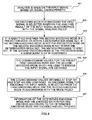
- Step 402 An encoding mode for encoding the input signal frame is selected based on the analysis result of the input signal frame in accordance with the signal analysis policy. Such encoding mode is referred to as a second encoding mode. Different signal characteristics correspond to different encoding modes.
- the encoding mode for the input signal frame may be determined in accordance with a preset signal analysis policy.
- the signal analysis policy may include analyzing various signal characteristics to select a second encoding mode; taking priority to conduct the selection based on the analysis result. For instance, it is first determined if the signal is a constant signal. Then it is determined if the signal is a multi-value signal. Lastly, it is determined if the signal is a pulse signal.
- the determination process may be as follows. Based on the analysis result obtained at step 401, it is first determined whether the input signal frame is a constant signal. When the whole input frame signal is a constant signal, a corresponding constant encoding mode is selected as the second encoding mode. Alternatively, it is further determined whether the frame signal is a special constant frame signal. If it is a special constant frame signal, a special constant encoding mode is selected; otherwise, a normal constant encoding mode is selected. If the signal is not a constant signal, it is determined if the signal is a multi-valued signal. If the whole input signal frame includes two values, a multi-valued encoding mode is selected as the second encoding mode.
- the rest may be deduced by analogy until the determination of the signal characteristic is completed.
- the above sequence for determination may also be adjusted according to real situation.
- the signal analysis policy includes the priority of determination of different signal characteristic and determination on which signal characteristic needs to be analyzed.
- the corresponding encoding modes includes, but not limited to, a constant encoding mode, a pulse encoding mode, a multi-valued encoding mode or a run-length encoding mode.
- a prediction encoding mode is used as the second encoding mode.
- FIG. 5 illustrates a determination process based on the signal analysis policy.
- Step 402 may also be performed concurrently to step 401. After an analysis to one signal characteristic, it may be determined based on the signal analysis policy whether the encoding mode corresponding to the signal characteristic can be selected as the second encoding mode. Step 402 may also be performed on the basis of the completion of step 401 to select the second encoding mode in accordance with the signal analysis policy. The above steps may allow for effectively selecting an encoding mode based on the signal characteristics so that the compressing efficiency is further guaranteed.
- Step 403 It is identified whether the second encoding mode is a prediction mode. If the second encoding mode is not the prediction mode, the method proceeds to step 407. If the second encoding mode is the prediction mode, a subsequent step is performed.
- Step 404 The coding demand value for the preset first encoding mode which is used to encode the input signal frame is obtained.
- Step 404 may be implemented in at least two ways.
- the first way is to encode the input frame signal frame by frame with the first encoding mode and calculate the coding demand value required for encoding.
- the second way is to estimate the coding demand value required for encoding the input frame signal frame by frame with the first encoding mode and obtain an estimate for the coding demand value.
- the first encoding mode may be a dynamic range encoding mode.
- the coding demand value for the dynamic range encoding mode may include the number of bits or the number of bytes required for encoding.
- the number of bits or the number of bytes is used to represent the characteristic information of the complexity for encoding the input signal frame.
- the present embodiment is described in an example of the number of bits.
- the number of bits required for encoding each sample point is calculated based on the minimum sample point value and the maximum sample point value of the signal to be encoded.
- determination may be performed prior to step 404 to obtain the dynamic range of the signal to be encoded.
- the dynamic range is compared with a predetermined threshold. When the dynamic range of the signal to be encoded is smaller than or equal to the preset threshold, step 404 is performed. Or, the dynamic range is below a threshold, or above a threshold, or below threshold 1 and above threshold 2, or the number of bits for the second encoding mode is higher than a threshold.
- Step 405 The coding demand value for the second encoding mode which is used to encode the input signal frame is obtained.
- the step may be performed prior to step 404, after step 404 and/or performed concurrently to step 404. Similar to the method in step 404, the coding demand value for the second encoding mode which is used to encode the input signal frame is obtained in accordance with the method for calculating the number of bits or the number of bytes required for encoding the input signal frame using the second encoding mode. Alternatively, determination may be carried out prior to step 405. If the number of bits for the second encoding mode is larger than a threshold, step 406 is performed.
- Step 406 The coding demand values obtained at step 404 and step 405 are compared. An encoding mode for encoding the input signal frame is selected from the first encoding mode and the second encoding mode in accordance with a mode selection policy.
- the mode selection policy includes determining a minimum coding demand value from the obtained coding demand values. According to this mode selection policy, the first mode for encoding the input signal frame is selected if the coding demand value required for the first mode is less than the coding demand value required for the second mode. If the coding demand value required for the first mode is no less than the coding demand value required for the second mode, a second encoding mode is selected for encoding the input signal frame.
- the mode selection policy further includes determining, from the obtained coding demand values, a coding demand value which is closest to the threshold. According to this mode selection policy, the code demand values for theses two modes are compared with a preset threshold.
- the encoding mode corresponding to the coding demand value having a smaller absolute value of the difference between the coding demand value and the threshold is selected for encoding the input signal frame.
- the encoding mode corresponding to the coding demand value smaller than the threshold is selected for encoding the input signal frame.
- the mode selection policy further includes adopting preferably one of the first encoding mode and at least one of the other encoding modes used to perform encoding. In different environment, sometimes, there is a need to perform encoding in a preset encoding mode. Therefore, the mode which is employed first still exists.
- the mode policy for selecting, from the first encoding mode and the second encoding mode, an encoding mode for the input signal frame is not limited to the above types.
- the mode selection policy covers all the solutions which can be conceived by those skilled in the art.
- Step 407 Information of the determined encoding mode and the encoded data which are encoded according to the determined encoding mode are encoded and multiplexed.
- the information of the first encoding mode and the encoding result at step 404 are multiplexed and encoded with the parameters required for the first encoding mode.
- the multiplexed data are then output to the decoder.
- the information of the second encoding mode and the encoding result at step 405 are multiplexed and encoded with the parameters required for the second encoding mode.
- the multiplexed data are then output to the decoder.
- the input signal frame is encoded frame by frame using the encoding mode determined at step 406 to obtain the encoded data.
- the input signal frame is encoded and multiplexed based on the identified result.
- the encoded input signal frame, the encoding mode identifier and the parameters required for encoding are multiplexed.
- the parameters required for encoding includes the number of sample points, a minimum value of the sample points, and the number of bits for encoding each sample point.
- the parameters may include a prediction coefficient, a prediction order, entropy coding parameters, etc, which are dependent on the selected encoding mode.
- the selected encoding mode is used to compress and encode the input signal frame.
- an encoding mode identifier corresponding to the second encoding mode is generated and sent.
- the input signal frame is encoded using the second encoding mode via the second encoding module.
- the input signal frame is encoded by a dynamic range encoding module (taking the dynamic range encoding module as an example).
- the frame header information of the signal to be encoded, the information of the sample point value of the signal to be encoded and the encoding mode identifier corresponding to the dynamic range encoding mode are sent.
- the frame header information is the minimum value of the sample point of the signal to be encoded and the number of bits for encoding each sample point.
- the information of the sample point value of the signal to be encoded is the sample point value of the signal to be encoded.
- the frame header information of the signal to be encoded is encoded based on the encoding mode identifier corresponding to the dynamic range encoding mode.
- the information of the sample point of the signal to be encoded is encoded bit by bit based on the number of bits required for encoding each sample point.
- step 403 may include the following steps.
- Step 403 It is identified whether the second encoding mode is one of the encoding modes in a determination mode set.
- the determination mode set is preset.
- the determination mode set may include at least one encoding mode.
- the at least one encoding mode may be a prediction mode or other mode which differs from the first encoding mode.
- the second encoding mode is determined first. If the second encoding mode is not within the determination mode set, step 407 is performed to encode the input frame signal using the second encoding mode, and the information of the second encoding mode and the encoded data which are encoded using the second encoding mode multiplexed; otherwise, a subsequent step is performed.
- an encoding method is introduced to accommodate different encoding modes.
- a second encoding mode for encoding the frame signal is selected based on an analysis on the signal characteristic. If the selected second encoding mode does not belong to the determination mode set, the signal is encoded and output immediately. If the selected second encoding mode is within the determination mode set, an optimal encoding mode will be selected based on the coding demand values for the first encoding mode and the second encoding mode which are used to encode the input frame signal.
- effective switching is performed among different encoding modes based on the input signal frame and different coding policy when a signal is compressed and encoded. Accordingly, different requirements for complexity and compression efficiency can be met. Therefore, the compression efficiency is effectively enhanced by sacrificing less complexity.
- FIG. 6 is a flowchart according to an embodiment of the present invention. The flowchart includes the following steps.
- Step 601 The coding demand values for the first encoding mode and one of the other encoding modes which are used to encode an input frame signal are obtained.
- the first encoding mode may be a dynamic range encoding mode.
- the at least one of the other encoding modes is other encoding mode differing from the dynamic range encoding mode.
- this mode can be a prediction mode.
- other encoding mode shall not be excluded.
- Step 602 An encoding mode for encoding the input frame signal is selected from the encoding modes based on the coding demand values in accordance with the mode selection policy.
- Step 603 Information of the determined encoding mode and the encoded data which are encoded according to the determined encoding mode are multiplexed.
- coding demand values for different encoding modes are estimated directly.
- the encoding mode for encoding the input signal frame is selected therefrom, thereby reducing implementation complexity.
- an encoding method is introduced to accommodate different encoding modes.
- a generic encoding method and determining the coding demand values for the first encoding mode and the second encoding mode effective switching is performed among different encoding modes based on the input signal frame and different coding policy when a signal is compressed and encoded. Accordingly, different requirements for complexity and compression efficiency can be met. Therefore, the compression efficiency is effectively enhanced by sacrificing less complexity.
- FIG. 7 is a flowchart according to an embodiment of the present invention. The flowchart includes the following steps.
- Step 801 The coding demand value for the first encoding mode which is used to encode the input frame signal is obtained.
- Step 801 may be implemented in at least two ways.
- the first way is to encode the input frame signal by frame using the first encoding mode and calculate the coding demand value required for encoding.
- the second way is to estimate the coding demand value for the first encoding mode which is used to encode the input frame signal by frame and obtain an estimate for the coding demand value.
- the first encoding mode may be a dynamic range encoding mode.
- the coding demand value for the dynamic range encoding mode may include the number of bits or the number of bytes required for encoding.
- the number of bits or the number of bytes is used to represent the characteristic information of the complexity for coding the input signal frame.
- the present embodiment is described in an example of the number of bits.
- the number of bits required for encoding each sample point is calculated based on the minimum sample point value and the maximum sample point value of the signal to be encoded.
- code_bits log 2 [(max(x) - min(x) +1)].
- Step 802 The coding demand value for the at least one of the other encoding modes which is used to encode the input frame signal is obtained.
- a coding demand value for an encoding mode differing from the dynamic range encoding mode which is used to encode the input signal frame is obtained. Similar to the method in step 801, the coding demand value for the second encoding mode which is used to encode the input signal frame is obtained in accordance with the method for calculating the number of bits or the number of bytes required by the other encoding mode.
- the coding demand value may include the number of bits or the number of bytes required for encoding. Take the prediction encoding mode as an example. If the at least one of the other encoding modes is the prediction encoding mode, the process of obtaining the coding demand value for the prediction encoding mode may include the following steps.
- the number of bits for encoding the prediction encoding mode of the signal to be encoded is the sum of the number of bits required for encoding the residual signal of the signal to be encoded and the number of bits of the frame edge information of the signal to be encoded.
- the entropy coding is performed on the residual signal so as to obtain the number of bits required for encoding the residual signal.
- the residual signal is obtained based on the prediction order and the prediction coefficient.
- entropy coding is performed on the residual signal based on the entropy coding parameters.
- the characteristic of the entropy coding can be utilized to simplify the calculation of the number of bits required for encoding the residual signal. Take Rice coding as an example.
- the input value is m.
- the Rice parameter is s.
- the required number of bits can be estimated according to the characteristic. Consequently, the complexity of the solution is reduced.
- the frame edge information includes a frame length parameter, a prediction parameter and an entropy coding parameter.
- the frame length parameter is used to identify the number of sample points contained in the current frame.
- the prediction parameter indicates information required for linear prediction, such as prediction order and prediction coefficient.
- For the entropy coding parameters take Rice coding as an example. In the Rice coding, to optimize the encoding efficiency, the corresponding parameters may vary as the signal varies.
- the coding demand value can be estimated according to the characteristics of the input signal frame.
- the foregoing is based on the prediction encoding mode by way of example only.
- the coding demand values for various encoding modes can be obtained.
- the obtaining method is applicable to the encoding method different than the encoding mode itself.
- the demand encoding value can be obtained regardless of the encoding modes.
- one or more encoding modes can be selected from various encoding modes to serve as the at least one of the other encoding modes so that the complexity in computing the coding demand value can be reduced.
- step 801 and step 802 can be switched, or step 801 and step 802 can be performed concurrently.
- Step 803 The coding demand values for at least two encoding modes obtained at step 801 and step 802 are compared. An encoding mode for encoding the input signal frame is selected from the above encoding modes in accordance with the mode selection policy.
- various coding demand values obtained at step 802 may be compared in accordance with the mode selection policy first and further compared with the various coding demand values obtained at step 801 in accordance with the mode selection policy.
- various coding demand values obtained at step 801 and step 802 are compared together directly.
- the difference between the two approaches is that the two step comparison may adopt a different mode selection policy in each step of the comparison, whereas one step comparison simply adopts one mode selection policy.
- the mode selection policy includes determining the minimum coding demand value from the obtained coding demand values. According to this mode selection policy, the first mode is selected as the encoding mode for encoding the input signal frame if the coding demand value required for the first mode is less than the coding demand value required for the second mode. A second encoding mode is selected as the encoding mode for encoding the input signal frame if the coding demand value required for the first mode is no less than the coding demand value required for the second mode.
- the mode selection policy further includes determining, from the obtained coding demand values, a coding demand value which is closest to the threshold. According to this mode selection policy, the coding demand values for theses two modes are compared with a preset threshold.
- the encoding mode corresponding to the coding demand value having a smaller absolute value of the difference between the coding demand value and the threshold is selected for encoding the input signal frame.
- the encoding mode corresponding to the coding demand value smaller than the threshold is selected for encoding the input signal frame.
- the mode selection policy further includes adopting preferably one of the first encoding mode and at least one of the other encoding modes for performing encoding. In different environments, sometimes, there is a need to implement encoding in a preset encoding mode. Therefore, the mode which is employed first still exists.
- the mode policy for selecting, from the first encoding mode and the second encoding mode, an encoding mode for the input signal frame is not limited to the above types.
- the mode selection policy covers all the solutions which can be conceived by those skilled in the art. Take the two step comparison as an example.
- the encoding modes corresponding to one or more coding demand values may be obtained based on step 802 where the encoding modes corresponding to the coding demand value smaller than a threshold serves as the encoding mode for the input signal frame.
- the method for determining the minimum coding demand value is employed to determine the encoding mode for encoding the input signal frame.
- Step 804 Information of the determined encoding mode and the encoded data which are encoded according to the determined encoding mode are encoded and multiplexed.
- the information of the encoded mode and the encoding result obtained at step 801 or 802 are encoded and multiplexed, according to the encoding mode determined at step 803, with the parameters required for encoding in accordance with the encoding mode.
- the multiplexed result is output to the decoder. If the coding demand value is obtained by the estimation method employed at step 801 and step 802, then, at step 804, the input signal frame is encoded frame by frame using the encoding mode determined at step 803 to obtain the encoded data.
- the encoded input signal frame, the encoding mode identifier and the parameters required for encoding are multiplexed.
- the parameters required for encoding includes the number of sample points, minimum value of the sample points, the number of bits required for encoding each sample point. Also, the parameters may include a prediction coefficient, a prediction order, and an entropy coding parameter, etc.
- the selected encoding mode is used to compress and encode the input signal frame.
- the input signal frame is encoded by a dynamic range encoding module (taking the dynamic range encoding module as an example).
- the frame header information of the signal to be encoded, the information of the sample point value of the signal to be encoded and the encoding mode identifier corresponding to the dynamic range encoding mode are sent.
- the frame header information is the minimum value of the sample points of the signal to be encoded and the number of bits for encoding each sample point.
- the information of the sample value of the signal to be encoded is the sample value of the signal to be encoded.
- the frame header information of the signal to be encoded is encoded based on the encoding mode identifier corresponding to the dynamic range encoding mode.
- the information of the sample of the signal to be encoded is encoded bit by bit based on the number of bits required for encoding each sample.
- an encoding method is introduced to accommodate different encoding modes.
- a generic encoding method effective switching is performed among different encoding modes based on the input signal frame and different coding policy when a signal is compressed and encoded. Accordingly, different requirements for complexity and compression efficiency can be met. Therefore, the compression efficiency is effectively enhanced by sacrificing less complexity.
- FIG. 8 is a flowchart of a decoding method according to an embodiment of the present invention. The method includes the following steps.
- Step 901 A multiplexed signal which is encoded and transmitted is demultiplexed so as to obtain the information of an encoding mode for encoding a frame signal and encoded data which are encoded according to the encoding mode.
- Step 902 The encoded data which has been demultiplexed is decoded based on the information of the encoding mode so as to obtain the frame signal.
- the encoding mode is obtained at the encoding end in accordance with the following steps.
- the coding demand value for the first encoding mode and one of the other encoding modes which are used to encode an input frame signal are obtained.
- An encoding mode for encoding the input frame signal is determined, from the encoding modes based on the coding demand values in accordance with the mode selection policy.
- the multiplexed signal is demultiplexed and the signal to be decoded and the encoding mode identifier are sent to a decoding unit.
- a decoding mode for decoding the signal to be decoded is determined based on the demultiplexed encoding mode identifier. If the encoding mode corresponding to the encoding mode identifier is a dynamic range encoding mode, the decoding mode for the signal to be decoded is a dynamic range decoding mode.
- the decoding mode for decoding the signal to be decoded is a decoding mode corresponding to the other decoding mode, such as a prediction decoding mode.
- the prediction decoding mode Take the prediction decoding mode as an example.
- Residual signals are obtained by performing an entropy decoding on the signal to be decoded according to the entropy encoding parameters. The residual signals are combined based on the demultiplexed prediction coefficient and the prediction order so that a signal is reconstructed losslessly.
- a decoding method is introduced to accommodate different decoding modes.
- a generic decoding method and decoding the signal using a reverse process of the encoding process effective switching is performed among different encoding modes based on the input signal frame and different coding policy when a signal is compressed and encoded. Accordingly, different requirements for complexity and compression efficiency can be met. Therefore, the compression/decompression efficiency is effectively enhanced by sacrificing less complexity.
- FIG. 9 illustrates a diagram of an encoding system according to an embodiment of the present invention.
- the system includes a signal receiving apparatus 01, an encoding mode determination apparatus 02, an encoding apparatus 03 and a multiplexing and output apparatus 04.
- the signal input apparatus 01 is configured to receive an input signal frame.
- the output signal is a signal to be encoded.
- the encoding mode determination apparatus 02 is configured to analyze signal characteristic of the input frame signal, select a second encoding mode for encoding the input frame signal, obtain coding demand values for a preset first encoding mode and the second encoding mode which are used to encode the input frame signal; determine, from the above encoding modes based on the coding demand values, an encoding mode for encoding the input frame signal.
- the encoding apparatus 03 is configured to encode the input frame signal using the determined encoding mode.
- the multiplexing and output apparatus 04 is configured to multiplex information of the determined encoding mode and encoded data which are encoded according to the determined encoding mode.
- the encoding apparatus 03 is comprised of encoders which perform with different encoding modes.
- the encoding mode determination apparatus 02 may be coupled to the encoding apparatus 03, or may be coupled to the multiplexing and output apparatus 04.
- the encoding mode determination apparatus 02 obtains an estimate of the coding demand value by way of an estimation method.
- the determined encoding mode is sent to the encoding apparatus 03 which then encodes the input signal frame with the encoding mode and sends the encoding result to the multiplexing and output apparatus 04.
- the multiplexing and output apparatus 04 sends the multiplexed data to the decoder for decoding.
- the encoding apparatus 03 and the encoding mode determination apparatus 02 may be in a logic entity or may be located within the encoding mode determination apparatus 02, or may be separate logic entities.
- the process that the encoding mode determination apparatus 02 obtains the coding demand value includes using the encoding apparatus 03 to obtain the coding demand value required for encoding by employing an encoding mode to perform the encoding.
- the data encoded with the encoding mode, the mode identifier and the encoding parameters are sent to the multiplexing and output apparatus.
- the multiplexing and output apparatus multiplexes the received data and outputs the multiplexed result to the decoder for decoding.
- an encoding system is introduced to accommodate different encoding modes.
- a generic encoding system effective switching is performed among different encoding modes based on the input signal frame and different coding policy when a signal is compressed and encoded. Accordingly, different requirements for complexity and compression efficiency can be met. Therefore, the compression efficiency is effectively enhanced by sacrificing less complexity.
- the encoding operation under different encoding modes is performed by different encoder, including a dynamic range encoder, a constant encoder, a prediction encoder, etc.
- the input signal frame may be a PCM signal, like a signal encoded point by point under G. 711 standard, or other signal which is applicable to the above operations in the embodiments, or signals which can be unambiguously conceived from the above embodiments by those skilled in the art.
- the program may be stored in a computer readable storage media. During execution, the program may include the procedures of the methods according to various embodiments as mentioned above.
- the storage media may be a magnetic disc, an optical disc, a Read-Only Memory (ROM) or a Random Access Memory (RAM), etc.
Applications Claiming Priority (2)
| Application Number | Priority Date | Filing Date | Title |
|---|---|---|---|
| CN200910107564.4A CN101615910B (zh) | 2009-05-31 | 2009-05-31 | 压缩编码的方法、装置和设备以及压缩解码方法 |
| EP10005248.9A EP2256723B1 (en) | 2009-05-31 | 2010-05-19 | Encoding method and apparatus |
Related Parent Applications (1)
| Application Number | Title | Priority Date | Filing Date |
|---|---|---|---|
| EP10005248.9A Division EP2256723B1 (en) | 2009-05-31 | 2010-05-19 | Encoding method and apparatus |
Publications (1)
| Publication Number | Publication Date |
|---|---|
| EP2511905A1 true EP2511905A1 (en) | 2012-10-17 |
Family
ID=41495371
Family Applications (2)
| Application Number | Title | Priority Date | Filing Date |
|---|---|---|---|
| EP12175501A Withdrawn EP2511905A1 (en) | 2009-05-31 | 2010-05-19 | Encoding method, apparatus and device and decoding method |
| EP10005248.9A Active EP2256723B1 (en) | 2009-05-31 | 2010-05-19 | Encoding method and apparatus |
Family Applications After (1)
| Application Number | Title | Priority Date | Filing Date |
|---|---|---|---|
| EP10005248.9A Active EP2256723B1 (en) | 2009-05-31 | 2010-05-19 | Encoding method and apparatus |
Country Status (5)
| Country | Link |
|---|---|
| US (1) | US7835906B1 (zh) |
| EP (2) | EP2511905A1 (zh) |
| JP (2) | JP5017418B2 (zh) |
| KR (1) | KR101162193B1 (zh) |
| CN (1) | CN101615910B (zh) |
Families Citing this family (12)
| Publication number | Priority date | Publication date | Assignee | Title |
|---|---|---|---|---|
| WO2010087157A1 (ja) * | 2009-01-29 | 2010-08-05 | パナソニック株式会社 | 画像符号化方法及び画像復号方法 |
| CN101615910B (zh) * | 2009-05-31 | 2010-12-22 | 华为技术有限公司 | 压缩编码的方法、装置和设备以及压缩解码方法 |
| WO2014030938A1 (ko) * | 2012-08-22 | 2014-02-27 | 한국전자통신연구원 | 오디오 부호화 장치 및 방법, 오디오 복호화 장치 및 방법 |
| US9711150B2 (en) | 2012-08-22 | 2017-07-18 | Electronics And Telecommunications Research Institute | Audio encoding apparatus and method, and audio decoding apparatus and method |
| US10468033B2 (en) | 2013-09-13 | 2019-11-05 | Samsung Electronics Co., Ltd. | Energy lossless coding method and apparatus, signal coding method and apparatus, energy lossless decoding method and apparatus, and signal decoding method and apparatus |
| JP6302071B2 (ja) * | 2013-09-13 | 2018-03-28 | サムスン エレクトロニクス カンパニー リミテッド | 無損失符号化方法及び無損失復号化方法 |
| JP6196117B2 (ja) * | 2013-10-08 | 2017-09-13 | 株式会社東芝 | 画像符号化装置及び画像復号装置 |
| CN107424621B (zh) * | 2014-06-24 | 2021-10-26 | 华为技术有限公司 | 音频编码方法和装置 |
| CN111968656B (zh) * | 2014-07-28 | 2023-11-10 | 三星电子株式会社 | 信号编码方法和装置以及信号解码方法和装置 |
| CN104811722B (zh) * | 2015-04-16 | 2019-05-07 | 华为技术有限公司 | 一种视频数据的编解码方法及装置 |
| CN112955800B (zh) | 2018-10-25 | 2023-03-10 | 富士胶片株式会社 | 透镜镜筒 |
| EP4318954A1 (en) * | 2021-03-23 | 2024-02-07 | Panasonic Intellectual Property Corporation of America | Encoding device, decoding device, encoding method, and decoding method |
Citations (2)
| Publication number | Priority date | Publication date | Assignee | Title |
|---|---|---|---|---|
| US7054809B1 (en) * | 1999-09-22 | 2006-05-30 | Mindspeed Technologies, Inc. | Rate selection method for selectable mode vocoder |
| EP2256723A1 (en) * | 2009-05-31 | 2010-12-01 | Huawei Technologies Co., Ltd. | Encoding method, apparatus and device and decoding method |
Family Cites Families (31)
| Publication number | Priority date | Publication date | Assignee | Title |
|---|---|---|---|---|
| JPH02144599A (ja) * | 1988-11-28 | 1990-06-04 | Hitachi Ltd | 音声分析合成方式 |
| JPH02288739A (ja) * | 1989-04-28 | 1990-11-28 | Fujitsu Ltd | 音声符号復号化伝送方式 |
| JPH07287600A (ja) * | 1994-04-19 | 1995-10-31 | Matsushita Electric Ind Co Ltd | 音声蓄積装置 |
| TW271524B (zh) * | 1994-08-05 | 1996-03-01 | Qualcomm Inc | |
| JP3339335B2 (ja) * | 1996-12-12 | 2002-10-28 | ヤマハ株式会社 | 圧縮符号化復号方式 |
| JPH10187199A (ja) * | 1996-12-24 | 1998-07-14 | Oki Electric Ind Co Ltd | 半導体記憶媒体記録装置及び半導体記憶媒体再生装置 |
| US7072832B1 (en) | 1998-08-24 | 2006-07-04 | Mindspeed Technologies, Inc. | System for speech encoding having an adaptive encoding arrangement |
| US6691084B2 (en) * | 1998-12-21 | 2004-02-10 | Qualcomm Incorporated | Multiple mode variable rate speech coding |
| US6574593B1 (en) * | 1999-09-22 | 2003-06-03 | Conexant Systems, Inc. | Codebook tables for encoding and decoding |
| US6959274B1 (en) * | 1999-09-22 | 2005-10-25 | Mindspeed Technologies, Inc. | Fixed rate speech compression system and method |
| JP2001142499A (ja) * | 1999-11-10 | 2001-05-25 | Nec Corp | 音声符号化装置ならびに音声復号化装置 |
| US6625226B1 (en) * | 1999-12-03 | 2003-09-23 | Allen Gersho | Variable bit rate coder, and associated method, for a communication station operable in a communication system |
| AU2547201A (en) | 2000-01-11 | 2001-07-24 | Matsushita Electric Industrial Co., Ltd. | Multi-mode voice encoding device and decoding device |
| AU2001241672A1 (en) | 2000-02-25 | 2001-09-03 | Physical Optics Corporation | Method and apparatus for optimized lossless compression using a plurality of coders |
| JP2002247137A (ja) * | 2000-04-25 | 2002-08-30 | Canon Inc | 通信装置及び通信方法 |
| JP2002290973A (ja) * | 2001-03-28 | 2002-10-04 | Mitsubishi Electric Corp | マルチメディア通信装置 |
| JP2002351495A (ja) * | 2001-05-22 | 2002-12-06 | Hitachi Kokusai Electric Inc | 音声符号化及び復号装置 |
| US7536305B2 (en) | 2002-09-04 | 2009-05-19 | Microsoft Corporation | Mixed lossless audio compression |
| JP4728568B2 (ja) * | 2002-09-04 | 2011-07-20 | マイクロソフト コーポレーション | レベル・モードとラン・レングス/レベル・モードの間での符号化を適応させるエントロピー符号化 |
| US7613606B2 (en) * | 2003-10-02 | 2009-11-03 | Nokia Corporation | Speech codecs |
| GB0326262D0 (en) * | 2003-11-11 | 2003-12-17 | Nokia Corp | Speech codecs |
| FI118835B (fi) * | 2004-02-23 | 2008-03-31 | Nokia Corp | Koodausmallin valinta |
| GB0408856D0 (en) * | 2004-04-21 | 2004-05-26 | Nokia Corp | Signal encoding |
| US7739120B2 (en) | 2004-05-17 | 2010-06-15 | Nokia Corporation | Selection of coding models for encoding an audio signal |
| JP2006154350A (ja) * | 2004-11-30 | 2006-06-15 | Matsushita Electric Ind Co Ltd | 符号化データ変換装置 |
| KR100707174B1 (ko) * | 2004-12-31 | 2007-04-13 | 삼성전자주식회사 | 광대역 음성 부호화 및 복호화 시스템에서 고대역 음성부호화 및 복호화 장치와 그 방법 |
| US7599840B2 (en) * | 2005-07-15 | 2009-10-06 | Microsoft Corporation | Selectively using multiple entropy models in adaptive coding and decoding |
| EP1770915A1 (en) | 2005-09-29 | 2007-04-04 | Matsushita Electric Industrial Co., Ltd. | Policy control in the evolved system architecture |
| US8060363B2 (en) | 2007-02-13 | 2011-11-15 | Nokia Corporation | Audio signal encoding |
| CN100524462C (zh) * | 2007-09-15 | 2009-08-05 | 华为技术有限公司 | 对高带信号进行帧错误隐藏的方法及装置 |
| JP4918108B2 (ja) * | 2009-02-18 | 2012-04-18 | 日本電信電話株式会社 | 符号化方法、符号化装置、復号方法、復号装置、プログラム及び記録媒体 |
-
2009
- 2009-05-31 CN CN200910107564.4A patent/CN101615910B/zh active Active
-
2010
- 2010-05-19 EP EP12175501A patent/EP2511905A1/en not_active Withdrawn
- 2010-05-19 EP EP10005248.9A patent/EP2256723B1/en active Active
- 2010-05-19 KR KR1020100046858A patent/KR101162193B1/ko active IP Right Grant
- 2010-05-21 JP JP2010117289A patent/JP5017418B2/ja active Active
- 2010-05-28 US US12/790,345 patent/US7835906B1/en active Active
-
2012
- 2012-06-11 JP JP2012131683A patent/JP5456097B2/ja active Active
Patent Citations (2)
| Publication number | Priority date | Publication date | Assignee | Title |
|---|---|---|---|---|
| US7054809B1 (en) * | 1999-09-22 | 2006-05-30 | Mindspeed Technologies, Inc. | Rate selection method for selectable mode vocoder |
| EP2256723A1 (en) * | 2009-05-31 | 2010-12-01 | Huawei Technologies Co., Ltd. | Encoding method, apparatus and device and decoding method |
Non-Patent Citations (4)
| Title |
|---|
| "Pulse code modulation (PCM) of voice frequencies; G.711 (11/88)", ITU-T STANDARD, INTERNATIONAL TELECOMMUNICATION UNION, GENEVA ; CH, no. G.711 (11/88), 25 November 1988 (1988-11-25), pages 1 - 12, XP017460946 * |
| INTERNATIONAL TELECOMMUNICATION UNION: "Lossless compression of G.711 pulse code modulation", 1 September 2009 (2009-09-01), pages I - 66, XP002598950, Retrieved from the Internet <URL:http://mirror.itu.int/dms/pages/itu-t/rec/g/T-REC-G.711.0-200909-I.html> [retrieved on 20100902] * |
| MICHAEL A RAMALHO CISCO SYSTEMS ET AL: "A G711 Lossless Compression Algorithm Proposal;AC-0710-Q10-08", ITU-T DRAFTS ; STUDY PERIOD 2005-2008, INTERNATIONAL TELECOMMUNICATION UNION, GENEVA ; CH, vol. Study Group 16 ; 10/16, 28 September 2007 (2007-09-28), pages 1 - 21, XP017543474 * |
| MICHAEL A RAMALHO CISCO SYSTEMS ET AL: "Recommendation for G.711-LLC Terms of Reference Parameters", ITU-T DRAFTS ; STUDY PERIOD 2005-2008, INTERNATIONAL TELECOMMUNICATION UNION, GENEVA ; CH, vol. Study Group 16 ; 10/16, 4 April 2008 (2008-04-04), pages 1 - 5, XP017542009 * |
Also Published As
| Publication number | Publication date |
|---|---|
| EP2256723B1 (en) | 2013-10-16 |
| CN101615910A (zh) | 2009-12-30 |
| JP5456097B2 (ja) | 2014-03-26 |
| CN101615910B (zh) | 2010-12-22 |
| JP2011043795A (ja) | 2011-03-03 |
| US7835906B1 (en) | 2010-11-16 |
| JP2012194574A (ja) | 2012-10-11 |
| EP2256723A1 (en) | 2010-12-01 |
| KR101162193B1 (ko) | 2012-07-05 |
| KR20100129683A (ko) | 2010-12-09 |
| US20100305955A1 (en) | 2010-12-02 |
| JP5017418B2 (ja) | 2012-09-05 |
Similar Documents
| Publication | Publication Date | Title |
|---|---|---|
| US7835906B1 (en) | Encoding method, apparatus and device and decoding method | |
| US6647366B2 (en) | Rate control strategies for speech and music coding | |
| US9269366B2 (en) | Hybrid instantaneous/differential pitch period coding | |
| KR101395174B1 (ko) | 압축 코딩 및 디코딩 방법, 코더, 디코더, 및 코딩 장치 | |
| US8909521B2 (en) | Coding method, coding apparatus, coding program, and recording medium therefor | |
| US20140257824A1 (en) | Apparatus and a method for encoding an input signal | |
| US20030215013A1 (en) | Audio encoder with adaptive short window grouping | |
| KR20030014752A (ko) | 오디오 코딩 | |
| US20140006036A1 (en) | Method and apparatus for coding and decoding | |
| US20030093266A1 (en) | Speech coding apparatus, speech decoding apparatus and speech coding/decoding method | |
| KR102380642B1 (ko) | 스테레오 신호 인코딩 방법 및 인코딩 장치 | |
| US9094662B2 (en) | Encoder and decoder to encode signal into a scalable codec and to decode scalable codec, and encoding and decoding methods of encoding signal into scalable codec and decoding the scalable codec | |
| JP4022111B2 (ja) | 信号符号化装置及び信号符号化方法 | |
| KR101330209B1 (ko) | 스케일러블 데이터 산술 복호화 방법 | |
| JP2003216188A (ja) | オーディオ信号符号化方法、符号化装置、及び記憶媒体 | |
| KR101166650B1 (ko) | 배경 잡음 정보를 디코딩하기 위한 방법 및 수단 | |
| CN107077856B (zh) | 音频参数量化 | |
| KR20200038297A (ko) | 스테레오 신호 인코딩에서의 신호 재구성 방법 및 디바이스 | |
| EP1420401A1 (en) | Method and apparatus for converting a compressed audio data stream with fixed frame length including a bit reservoir feature into a different-format data stream | |
| JP5466618B2 (ja) | 符号化装置、復号装置、符号化方法、復号方法及びそのプログラム | |
| CN112400203A (zh) | 编码设备、编码方法、解码设备、解码方法、以及程序 | |
| Clüver et al. | Multiple-description coding of logarithmic PCM | |
| JP2004170494A (ja) | 音声符号化装置,音声符号化方法 | |
| JPH0356999A (ja) | 符号化装置 | |
| JP2003345394A (ja) | 音響信号符号化装置および音響信号符号化方法 |
Legal Events
| Date | Code | Title | Description |
|---|---|---|---|
| PUAI | Public reference made under article 153(3) epc to a published international application that has entered the european phase |
Free format text: ORIGINAL CODE: 0009012 |
|
| 17P | Request for examination filed |
Effective date: 20120709 |
|
| AC | Divisional application: reference to earlier application |
Ref document number: 2256723 Country of ref document: EP Kind code of ref document: P |
|
| AK | Designated contracting states |
Kind code of ref document: A1 Designated state(s): AL AT BE BG CH CY CZ DE DK EE ES FI FR GB GR HR HU IE IS IT LI LT LU LV MC MK MT NL NO PL PT RO SE SI SK SM TR |
|
| 17Q | First examination report despatched |
Effective date: 20140303 |
|
| STAA | Information on the status of an ep patent application or granted ep patent |
Free format text: STATUS: THE APPLICATION IS DEEMED TO BE WITHDRAWN |
|
| 18D | Application deemed to be withdrawn |
Effective date: 20140715 |
|
| REG | Reference to a national code |
Ref country code: DE Ref legal event code: R079 Free format text: PREVIOUS MAIN CLASS: G10L0019140000 Ipc: G10L0019040000 |
|
| REG | Reference to a national code |
Ref country code: DE Ref legal event code: R079 Free format text: PREVIOUS MAIN CLASS: G10L0019140000 Ipc: G10L0019040000 Effective date: 20150112 |