EP2511580A1 - Passage destiné à l'intégration dans un élément de paroi ou de sol - Google Patents
Passage destiné à l'intégration dans un élément de paroi ou de sol Download PDFInfo
- Publication number
- EP2511580A1 EP2511580A1 EP11002284A EP11002284A EP2511580A1 EP 2511580 A1 EP2511580 A1 EP 2511580A1 EP 11002284 A EP11002284 A EP 11002284A EP 11002284 A EP11002284 A EP 11002284A EP 2511580 A1 EP2511580 A1 EP 2511580A1
- Authority
- EP
- European Patent Office
- Prior art keywords
- pipe
- bushing
- web
- wall
- seal
- Prior art date
- Legal status (The legal status is an assumption and is not a legal conclusion. Google has not performed a legal analysis and makes no representation as to the accuracy of the status listed.)
- Granted
Links
- 238000009434 installation Methods 0.000 title claims description 17
- 238000004519 manufacturing process Methods 0.000 claims abstract description 4
- 239000000463 material Substances 0.000 claims description 28
- 230000009969 flowable effect Effects 0.000 claims description 9
- 238000005520 cutting process Methods 0.000 claims description 7
- 230000000295 complement effect Effects 0.000 claims description 6
- 239000004567 concrete Substances 0.000 claims description 5
- 239000004570 mortar (masonry) Substances 0.000 claims description 3
- 230000000630 rising effect Effects 0.000 claims description 3
- 238000000034 method Methods 0.000 abstract description 4
- 238000005192 partition Methods 0.000 description 14
- 230000001681 protective effect Effects 0.000 description 14
- 239000004568 cement Substances 0.000 description 5
- 238000009415 formwork Methods 0.000 description 5
- 239000004033 plastic Substances 0.000 description 5
- 229920003023 plastic Polymers 0.000 description 5
- 239000000835 fiber Substances 0.000 description 3
- 238000007789 sealing Methods 0.000 description 3
- PPBRXRYQALVLMV-UHFFFAOYSA-N Styrene Chemical compound C=CC1=CC=CC=C1 PPBRXRYQALVLMV-UHFFFAOYSA-N 0.000 description 2
- 238000005266 casting Methods 0.000 description 2
- 238000006243 chemical reaction Methods 0.000 description 2
- 239000002184 metal Substances 0.000 description 2
- 238000007711 solidification Methods 0.000 description 2
- 230000008023 solidification Effects 0.000 description 2
- XLYOFNOQVPJJNP-UHFFFAOYSA-N water Substances O XLYOFNOQVPJJNP-UHFFFAOYSA-N 0.000 description 2
- 239000004793 Polystyrene Substances 0.000 description 1
- 229920005830 Polyurethane Foam Polymers 0.000 description 1
- 229920006328 Styrofoam Polymers 0.000 description 1
- 208000021017 Weight Gain Diseases 0.000 description 1
- NIXOWILDQLNWCW-UHFFFAOYSA-N acrylic acid group Chemical group C(C=C)(=O)O NIXOWILDQLNWCW-UHFFFAOYSA-N 0.000 description 1
- 230000000903 blocking effect Effects 0.000 description 1
- 230000008859 change Effects 0.000 description 1
- 239000002131 composite material Substances 0.000 description 1
- 238000010276 construction Methods 0.000 description 1
- 238000001816 cooling Methods 0.000 description 1
- 230000001419 dependent effect Effects 0.000 description 1
- 238000006073 displacement reaction Methods 0.000 description 1
- 230000009977 dual effect Effects 0.000 description 1
- 239000013013 elastic material Substances 0.000 description 1
- 229920001971 elastomer Polymers 0.000 description 1
- 239000000806 elastomer Substances 0.000 description 1
- 230000007613 environmental effect Effects 0.000 description 1
- 239000006260 foam Substances 0.000 description 1
- 238000005187 foaming Methods 0.000 description 1
- 238000007373 indentation Methods 0.000 description 1
- 238000003780 insertion Methods 0.000 description 1
- 230000037431 insertion Effects 0.000 description 1
- 230000007246 mechanism Effects 0.000 description 1
- 238000000465 moulding Methods 0.000 description 1
- 230000003287 optical effect Effects 0.000 description 1
- 238000004806 packaging method and process Methods 0.000 description 1
- 230000035515 penetration Effects 0.000 description 1
- 230000002093 peripheral effect Effects 0.000 description 1
- 229920002223 polystyrene Polymers 0.000 description 1
- 238000002360 preparation method Methods 0.000 description 1
- 238000000926 separation method Methods 0.000 description 1
- 238000003892 spreading Methods 0.000 description 1
- 230000007480 spreading Effects 0.000 description 1
- 239000008261 styrofoam Substances 0.000 description 1
- 239000000725 suspension Substances 0.000 description 1
- 230000007704 transition Effects 0.000 description 1
- 230000004584 weight gain Effects 0.000 description 1
- 235000019786 weight gain Nutrition 0.000 description 1
Images


Classifications
-
- F—MECHANICAL ENGINEERING; LIGHTING; HEATING; WEAPONS; BLASTING
- F16—ENGINEERING ELEMENTS AND UNITS; GENERAL MEASURES FOR PRODUCING AND MAINTAINING EFFECTIVE FUNCTIONING OF MACHINES OR INSTALLATIONS; THERMAL INSULATION IN GENERAL
- F16L—PIPES; JOINTS OR FITTINGS FOR PIPES; SUPPORTS FOR PIPES, CABLES OR PROTECTIVE TUBING; MEANS FOR THERMAL INSULATION IN GENERAL
- F16L3/00—Supports for pipes, cables or protective tubing, e.g. hangers, holders, clamps, cleats, clips, brackets
- F16L3/22—Supports for pipes, cables or protective tubing, e.g. hangers, holders, clamps, cleats, clips, brackets specially adapted for supporting a number of parallel pipes at intervals
- F16L3/222—Supports for pipes, cables or protective tubing, e.g. hangers, holders, clamps, cleats, clips, brackets specially adapted for supporting a number of parallel pipes at intervals having single supports directly connected together
-
- E—FIXED CONSTRUCTIONS
- E04—BUILDING
- E04G—SCAFFOLDING; FORMS; SHUTTERING; BUILDING IMPLEMENTS OR AIDS, OR THEIR USE; HANDLING BUILDING MATERIALS ON THE SITE; REPAIRING, BREAKING-UP OR OTHER WORK ON EXISTING BUILDINGS
- E04G15/00—Forms or shutterings for making openings, cavities, slits, or channels
- E04G15/06—Forms or shutterings for making openings, cavities, slits, or channels for cavities or channels in walls of floors, e.g. for making chimneys
- E04G15/061—Non-reusable forms
-
- F—MECHANICAL ENGINEERING; LIGHTING; HEATING; WEAPONS; BLASTING
- F16—ENGINEERING ELEMENTS AND UNITS; GENERAL MEASURES FOR PRODUCING AND MAINTAINING EFFECTIVE FUNCTIONING OF MACHINES OR INSTALLATIONS; THERMAL INSULATION IN GENERAL
- F16L—PIPES; JOINTS OR FITTINGS FOR PIPES; SUPPORTS FOR PIPES, CABLES OR PROTECTIVE TUBING; MEANS FOR THERMAL INSULATION IN GENERAL
- F16L5/00—Devices for use where pipes, cables or protective tubing pass through walls or partitions
- F16L5/02—Sealing
- F16L5/08—Sealing by means of axial screws compressing a ring or sleeve
-
- F—MECHANICAL ENGINEERING; LIGHTING; HEATING; WEAPONS; BLASTING
- F16—ENGINEERING ELEMENTS AND UNITS; GENERAL MEASURES FOR PRODUCING AND MAINTAINING EFFECTIVE FUNCTIONING OF MACHINES OR INSTALLATIONS; THERMAL INSULATION IN GENERAL
- F16L—PIPES; JOINTS OR FITTINGS FOR PIPES; SUPPORTS FOR PIPES, CABLES OR PROTECTIVE TUBING; MEANS FOR THERMAL INSULATION IN GENERAL
- F16L5/00—Devices for use where pipes, cables or protective tubing pass through walls or partitions
- F16L5/02—Sealing
- F16L5/14—Sealing for double-walled or multi-channel pipes
-
- H—ELECTRICITY
- H02—GENERATION; CONVERSION OR DISTRIBUTION OF ELECTRIC POWER
- H02G—INSTALLATION OF ELECTRIC CABLES OR LINES, OR OF COMBINED OPTICAL AND ELECTRIC CABLES OR LINES
- H02G3/00—Installations of electric cables or lines or protective tubing therefor in or on buildings, equivalent structures or vehicles
- H02G3/22—Installations of cables or lines through walls, floors or ceilings, e.g. into buildings
Definitions
- the present invention relates to a provided for installation in a wall or floor element implementation with a tubular element through which a line can be passed.
- Such known as shaft feedthroughs are performed according to the prior art with a tube element made of fiber cement, which keeps a through opening after installation of the implementation between two sides of the wall or floor element. Through this, a line can then be performed, which is then sealed, for example, with an inserted sealing body against the pipe element.
- the object of the present invention is to provide a bushing with improved functional and functional properties.
- this object solves a performance with a tubular element, on the outside of which is provided away from the tube member web is provided whose vertical projection is spaced on the tube member to its ends, wherein the web has a connecting element, via which the implementation with a second implementation is connectable.
- a plurality (ie, at least two) bushings can be assembled to form a module having a plurality of pipe elements extending approximately parallel, for example, and then also installed together in the wall or floor element, for example, by pouring described in more detail below flowable and then solidifying material.
- Hierbel can vorortlichweiseweise either the module as a whole or initially a single implementation are positioned and aligned in a formwork, in the latter case, web and connecting element already predetermine the position of another implementation; in contrast to the prior art, therefore, not necessarily each implementation must be aligned individually, which helps reduce the effort during installation.
- the connectivity of the feedthroughs relates to at least one pair, preferably an arbitrary one-dimensional row and more preferably a two-dimensional arrangement.
- the web with the connecting element according to the invention is spaced apart from the ends of the tubular element, that is arranged after installation within the wall or floor element.
- the web and preferably also the connecting element are ideally not visible on either side of the wall or floor element - the arrangement also provides protection within, for example, later acting on an outside weather or moisture.
- the vertical projection of the web onto the pipe element according to the invention is spaced apart from the pipe ends, preferably in relation to the length of the pipe element measured in the pipe direction, more preferably at least 5, 10, 15, 20, 25, 30, 35 in this order % of the pipe length.
- the projection is perpendicular to a (parallel to the tube direction) center axis of the tubular element, so approximately in the case of a tubular element with a circular cross-section also perpendicular to the (approximately assumed to be smooth) outer wall of the tubular element.
- a tubular element with a circular cross-section is preferred, although a different cross-sectional shape is possible, such as a rectangular.
- the tube elements of a module then not in an end, lying near the tube ends area, but related to the tube direction rather centrally connected to each other. Apart from this, they preferably extend apart from one another, apart from devices which may be used for installation in wall or floor elements. This ensures a certain stability of the feedthrough module, such as when pouring into a. Wall or floor element that hits a pipe element material causes a force transfer. By an approximately central arrangement of the connecting elements and a correspondingly approximately "suspension" of the tubular element can then be achieved at least approximately a compensation of the lever forces occurring.
- the line may also be a gas, water or heat line, wherein a power, telecommunications, signal or data line is preferred.
- the connecting element is provided in duplicate as a first and a second positive locking element complementary thereto. If further preferably both a first and a second positive locking element are provided on a single web, a feedthrough module can advantageously also be constructed from only one single bushing type.
- the handling can be simplified by the form-fitting interlocking fasteners, which hold together about a plug-in or clamping mechanism, for example because no screw on or nut must be placed.
- the number of individual parts and thus the risk of loss for example after removal from packaging and prior to installation in the wall element, can be reduced.
- a plastic material is preferred for the pipe element, the web and the connecting element, which also offers cost advantages over other materials, such as metal or fiber cement. Furthermore, compared to the shaft liners made of fiber cement mentioned at the outset, weight gains can also be achieved in relation to bushings made of metal, which, for example, can simplify handling and reduce transport costs.
- the web is formed as a circumferential web seal, so this advantageously fulfills a dual function on the one hand as connection of passages to a module and on the other hand to block or extend creepage along the outside of the tubular element.
- the web or the web seal according to the invention are arranged within the wall element, because so in the case of a not adhering to the pipe element and web seal wall element material and a corresponding gap therebetween, the "height" of the web seal, so the Distance of a free edge of the web seal to the pipe element, is used twice for Kriechwegsverinrung; Otherwise, if the web seal were to adjoin one side of the wall element, moisture could penetrate the free edge of the web seal and the creepage distance would accordingly only be increased by about the simple height of the web seal.
- the web seal seen in the pipe direction has a polygonal outer shape and with complementary polygonal web seals further bushings can be assembled in addition to surface.
- the preferably continuous surface formed by the web seals and apart from the pipe elements is then arranged inside the wall element, for example substantially parallel to two mutually opposite side surfaces thereof.
- a web seal with a rectangular, particularly preferably square, outer shape, seen in the tube direction, is preferred, the connecting element being arranged on a side line of the rectangle, specifically in a preferred embodiment closer to one of the two corners on the sideline than the other, so in a corner area.
- the connecting element is arranged on a side line of the rectangle, specifically in a preferred embodiment closer to one of the two corners on the sideline than the other, so in a corner area.
- a second section extending away from the tubular element, the first section of the web seal, a second, along the tube direction of the first portion extending away portion is provided;
- the second portion extends T-shaped in two directions (each in the tube direction) away from the first portion.
- a corresponding second, extending in the tube direction portion of the web seal in particular with an installation with flowable and solidification shrinking material can have advantages, because in a lifting of the wall element material of the tubular element between the opposite side of the pipe element second portion and the wall element material still can remain in contact; the Wandelementmateriel may optionally be "pulled” by the shrinkage even against the second section.
- the web seal can for example be made of a hard, so on an application of force substantially low-deformation reacting material, such as a plastic material with acrylic Buthadlen styrene.
- tubular element and web seal are made of the same hard material in a preferred embodiment, the pipe element holds on the one hand a certain pressure during the casting stand and accordingly a through hole free. and extended or blocked the web seal on the other hand, with appropriate design geometrie employment creepage distances - despite a hard and therefore in the case of a shrinking wall element material essentially not nachfedernden web seal. It can therefore be dispensed, for example, on additional externally arranged sealing elements made of elastic material, which may also be advantageous in terms of cost.
- a the tube element occlusive, integrally formed with the tubular element partition wall is provided. This serves as a blind closure, so that the implementation can also be provided for later, so initially optional, passing a line, which multiplies the application possibilities of a single type wall element especially in the case of a feedthrough module with a plurality of pipe elements and therefore especially for prefabricated elements especially is advantageous.
- a pipe element without partition ie without blind closure
- an additional sealing element for example inserted into the pipe element, serving as blind plug press seal, causing additional costs and the Vorhalt or handling additional components necessary.
- a forming method is preferred for producing the implementation, in which a cavity formed by a mold then the shape of the cavity-accepting plastic material is supplied and the mold, the implementation, for example, after solidification of a previously flowable at elevated temperature plastic material or after cooling a reaction of the plastic material releases.
- the implementation can thus be injection-molded, for example, which is preferred; nevertheless, provided that in the following "injection-molded implementation", also forming methods in the just described generality be detected.
- a dividing wall extending transversely to the pipe direction can for example also be arranged in a plane with the web or the web seal, so that, for example, an injection-molded bushing can be removed from the plane by a movement of the molding tools.
- the partition can be knocked out, for example, with a hammer or separated with a cutting tool depending on the material condition.
- a breaking point facilitating the separation of the partition wall is provided, for example in a transition region from partition to pipe element.
- a locally measured in the tube direction thickness of the partition wall reduced, so be formed a notch; this can be approximately parallel to an inner wall of the tubular element running, also directly adjacent to this bordering, and preferably designed to be completely circumferential.
- Another embodiment relates to a tubular element with a stop provided therein, to which an additional tube can be inserted.
- cables in the outdoor area are often brought to a wall element in so-called protective tubes. so that the stop can give a preferred position for a protective tube to be inserted and thus ensure its adequate seating.
- the protective tube can also be additionally sealed against the pipe element, such as with an inserted into the pipe element, then arranged between the inner wall and the protective tube elastomer body;
- a transversely extending to the tube direction stop can also be provided, to which the elastomeric body can be inserted and which can then abut an end face of the tubular element or on a wall surface.
- the pipe element over its length in the pipe direction does not necessarily have a constant cross-sectional shape, in the case of a tubular element with a circular cross-section so for example, a diameter change, for example, to compensate for the wall thickness of a protective tube.
- one end of the bushing may be designed to receive a protective tube with a certain wall thickness and the diameter may be reduced by twice the wall thickness, so that (if the tube element sections of different diameter are coaxially arranged) no diameter exists between the tube element section of smaller diameter and the inner wall of the protective tube Diameter jump takes place and accordingly the risk is reduced that a cable caught during the passage.
- the diameter jump between the two tube element sections preferably takes place abruptly, so they are connected by a section extending essentially perpendicular to the tube direction, which ideally can simultaneously serve as a stop.
- This styrofoam plug for example, has a first outer surface extending along the tube direction and then at least partially against a tube inner wall surface, and preferably a second outer surface extending transversely to the tube direction (without the second outer surface, the plug could be a tubular body, which is possible but not preferred).
- the distance between the second outer surface and a pipe end and thus the portion of the first outer surface lying outside the pipe element can be varied, preferably by a displacement of the plug in the pipe direction.
- the plug which can be adjusted in the passage opening can then keep a through opening free even when pouring with flowable material beyond the tube end, so that the length of the passage (if necessary) has a minimum wall thickness pretends and in a thicker wall then the tube element together with the appropriately positioned plug a passage opening free.
- the second outer surface of the plug is spaced from the pipe end, after casting adjacent to a side surface of the wall element, so for example initially provided on a formwork, provided so that the first outer surface of the plug in the then solidified material a through hole from the pipe end to the Side surface of the wall element free.
- both pipe ends can be extended accordingly, so two plugs are provided.
- a plurality of wall element thicknesses can thus be realized with a single feedthrough type, ie the flexibility is increased; This is also advantageous in terms of cost, because it is not necessary to produce feedthroughs of different lengths, ie, in the case of an injection-molded feedthrough, the number of forming tools can be reduced.
- An embodiment further increasing the flexibility with regard to the possible wall thicknesses relates to a cutting of the pipe element in order to adapt to a wall element thickness, because such a minimum wall thickness is no longer limited by the original pipe element length.
- markings may be provided on the outside of the tubular element, which may correspond to approximately standardized wall thicknesses.
- a predetermined breaking point is provided for the cutting to the tube element, particularly preferably is an outside, ideally circumferential notch.
- the invention also relates to the use of a bushing with a tubular element, on the outside of which a web rising away from the pipe element is provided with a connecting element, specifically for installation in a wall or floor element.
- a bushing with a tubular element, on the outside of which a web rising away from the pipe element is provided with a connecting element, specifically for installation in a wall or floor element.
- the vertical projection of the web is spaced on the tubular element to its two ends, so that the web according to the invention arranged within the wall element, so as a whole can be positively enclosed by the solidified material. It is then based on the pipe direction solidified material on both sides of the web, ie on both sides of a plane which intersects the web and is perpendicular to the pipe direction.
- the flowable and then solidifying material is particularly preferably concrete or mortar, both of which contain cement as cement, which solidifies after being stirred with water as a result of chemical reactions.
- the invention also relates to the production of a prefabricated wall or floor element which is made of a flowable and then solidifying material.
- a prefabricated wall or floor element which is made of a flowable and then solidifying material.
- an implementation of the invention in a for the production of the wall. or floor element provided, optionally after cutting to length or in combination with (an) extending plug. and keeps in the then solidified material a through hole.
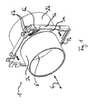
- FIG. 1 shows a passage 1 according to the invention with a tubular element 2, which is constructed in one piece from a front in the figure first portion 2a of smaller diameter and a rear portion 2b in the figure larger diameter.
- a web 3 formed here as a peripheral web seal rises on the outside perpendicular to the pipe direction 4 away from the pipe element 2.
- a second section 3b which extends in a T-shaped manner in the pipe direction 4 away from the first section 3a, adjoins, with reference to FIGS FIG. 3 Creepage distances explained in detail are lengthened along the outside of the tubular element 2 facing the wall element.
- connecting elements 5 are provided on a free edge of the web seal 3 facing away from the tube element 2, namely by a first, elongated pin-shaped type 5a and a second, for clamping of the first intended type 5b.
- a partition wall 6 closing off the tubular element 2 is provided.
- the partition 6 is as well as the diameter jump in FIG. 2 to recognize in a sectional view; the section plane is oriented parallel to the pipe direction 4 and includes a center axis of the pipe element 2.
- the diameter jump occurs abruptly, so that the pipe element sections 2a and b are connected by a section 7 extending perpendicular to the pipe direction 4. This results in a stop, up to which a protective tube (not shown) can be pushed into the end of the tubular element 2 facing away from the observer.
- the partition wall 6 closes the passage opening, thus blocking, for example, a passage of moisture, without the need for an additional, serving as a blind plug seal must be used.
- FIG. 3 is perpendicular to the pipe direction 4 looking a sectional view shown, wherein between the partition wall 6 and the inner wall of the tubular element section 2b indentations 31 can be seen, which represent a removal of the partition wall 6 facilitating predetermined breaking point. If a line is then passed through, the partition 6 can be knocked out.
- a line 41 are passed through the bushing 1.
- the line 41 is typically from a building exterior side area, ie in FIG. 4 from the left, introduced and outside the building in a protective tube 42 is guided, which can be inserted up to the stop 7 in the tubular element section 2b.
- the inner diameter of the tubular element section 2a is adapted to the inner diameter of the protective tube, there is no edge on the stop 7, at which the line 41, which is passed after the insertion of the protective tube 42, could get caught.
- FIG. 5 illustrates the installation of a passage according to the invention in a wall element, wherein for an end extension of the tubular element 2 plugs 51 are provided, because the wall to be produced is thicker than the tube element 2 long.
- the plugs 51 each have a first, parallel to the respective pipe element portion 2a, b extending and surface on the respective inner wall 52a, b adjacent outer surface 53a, b and a second, perpendicular to the first extending outer surface 54a, b.
- the plugs 51a, b of solidified foam are then pulled out of the respective tube element section 2a, b, so that they respectively engage with the second outer surface 54a, b on a formwork 55 intended for pouring concrete issue.
- the formwork 55 is filled with the passage 1 in a form-fittingly enclosing concrete, the portions of the plugs 51a lying outside the tubular element 2 in each case hold. b the tube element 2 on both sides extending through openings free.
- the bushing is arranged approximately in the center of the wall element and the plugs 51a, b are accordingly pulled out of the respective pipe element section 2a, b substantially equidistant.
- FIG. 5 It is also illustrated above how a possible creepage path 56 along the outside of the tubular element 2 is extended by the first section 3a of the web seal and the second section 3b extending away from it in a T-shaped manner.
- FIG. 6 shows a composed of four bushings 1 bushing module 61.
- the bushings 1 are connected to each other via the provided on their web seals 3 form-fitting elements 5a, b, so only via the web seals 3; otherwise the pipe elements 2 extend independently of each other, so in particular share no side walls.
- FIG. 7 a bushing 1 with web seal 3 and form-locking elements 5 is shown looking in a plan view in the pipe direction 4.
- the web seal 3 has a square outer shape, wherein each of the four side lines two positive locking elements 5a, b are provided, in each case adjacent to the corners of the square.
- the peg-shaped form-fitting elements 5a are thickened toward a free end 71a (cf. FIG. 8 ), wherein in a composite module 61, the thickened end 71 a in a complementary recess 72b of the brackets 5b comes to rest.
- FIG. 9 shown in a side view perpendicular to the pipe direction 4 looking.
Landscapes
- Engineering & Computer Science (AREA)
- General Engineering & Computer Science (AREA)
- Mechanical Engineering (AREA)
- Architecture (AREA)
- Civil Engineering (AREA)
- Structural Engineering (AREA)
- Installation Of Indoor Wiring (AREA)
Priority Applications (2)
| Application Number | Priority Date | Filing Date | Title |
|---|---|---|---|
| PL11002284T PL2511580T5 (pl) | 2011-03-21 | 2011-03-21 | Przepust izolowany do osadzenia w elemencie ściany albo podłogi |
| EP11002284.5A EP2511580B2 (fr) | 2011-03-21 | 2011-03-21 | Passage destiné à l'intégration dans un élément de paroi ou de sol |
Applications Claiming Priority (1)
| Application Number | Priority Date | Filing Date | Title |
|---|---|---|---|
| EP11002284.5A EP2511580B2 (fr) | 2011-03-21 | 2011-03-21 | Passage destiné à l'intégration dans un élément de paroi ou de sol |
Publications (3)
| Publication Number | Publication Date |
|---|---|
| EP2511580A1 true EP2511580A1 (fr) | 2012-10-17 |
| EP2511580B1 EP2511580B1 (fr) | 2013-05-29 |
| EP2511580B2 EP2511580B2 (fr) | 2020-11-25 |
Family
ID=44504333
Family Applications (1)
| Application Number | Title | Priority Date | Filing Date |
|---|---|---|---|
| EP11002284.5A Active EP2511580B2 (fr) | 2011-03-21 | 2011-03-21 | Passage destiné à l'intégration dans un élément de paroi ou de sol |
Country Status (2)
| Country | Link |
|---|---|
| EP (1) | EP2511580B2 (fr) |
| PL (1) | PL2511580T5 (fr) |
Cited By (5)
| Publication number | Priority date | Publication date | Assignee | Title |
|---|---|---|---|---|
| EP2728232A1 (fr) * | 2012-10-30 | 2014-05-07 | Hauff-Technik GmbH & Co. KG | Passage destiné à l'intégration dans un élément de paroi ou de sol |
| EP2851488A1 (fr) * | 2013-09-19 | 2015-03-25 | Hauff-Technik GmbH & Co. KG | Élément de pose à intégrer avec une conduite dans un élément de sol ou de paroi |
| EP2907927A1 (fr) | 2014-02-18 | 2015-08-19 | Ain Corporation | Dispositif de réservation de passages de canalisations |
| CN108277927A (zh) * | 2018-02-01 | 2018-07-13 | 华洲建设温州有限公司 | 现浇混凝土抗浮结构 |
| EP3404170B1 (fr) * | 2017-05-18 | 2021-05-05 | Hauff-Technik GmbH & Co. KG | Utilisation d'un passage encastrable dans un élément de mur ou de sol |
Citations (4)
| Publication number | Priority date | Publication date | Assignee | Title |
|---|---|---|---|---|
| DE958671C (de) * | 1952-10-06 | 1957-02-21 | Nils Brattberg Dipl Ing | Dichte Durchfuehrung fuer Leitungsbuendel durch eine Wand |
| GB2171139A (en) * | 1983-05-20 | 1986-08-20 | Werner Hauff | Apparatus for making a soffit for a feed-through ducting arrangement in a concrete wall |
| DE8700714U1 (fr) * | 1987-01-16 | 1987-03-05 | Betonbau Gmbh, 6833 Waghaeusel, De | |
| US6386550B1 (en) * | 2000-02-02 | 2002-05-14 | Stepcon Industries Inc. | Subterranean coupler |
Family Cites Families (10)
| Publication number | Priority date | Publication date | Assignee | Title |
|---|---|---|---|---|
| DE2411521A1 (de) † | 1974-03-11 | 1975-10-23 | Hauff Technik Kg | Dichte wanddurchfuehrung fuer kabel, leitungen o.dgl. |
| US4342462A (en) † | 1978-05-10 | 1982-08-03 | John Carlesimo | Adjustable seal member for conduit to manhole junction |
| DE3527220A1 (de) † | 1985-07-30 | 1987-02-12 | Wolfgang Von Dahmen | Rohrdurchfuehrung fuer waende von bauwerken |
| US5309688A (en) † | 1989-03-03 | 1994-05-10 | Paul Robertson | Concrete slab penetration unit for pipes |
| US5043536A (en) † | 1990-04-06 | 1991-08-27 | Hubbell Incorporated | Rotation-limiting knockout configuration |
| US5711536A (en) † | 1994-05-11 | 1998-01-27 | Tuf-Tite, Inc. | Seal component for use in on-site poured concrete or plastic tank or box components of fluid distribution systems |
| DE4427603C1 (de) † | 1994-08-04 | 1995-07-27 | Norbert Heinker | Vorrichtung zur Abdichtung von Rohrleitungen, Kabelkanälen od.dgl. |
| JP3860083B2 (ja) † | 2002-07-03 | 2006-12-20 | 株式会社三金 | コンクリート構造物の貫通孔形成用伸縮スリーブ |
| SE523975E (sv) † | 2002-10-10 | 2008-11-05 | Roxtec Ab | Ram |
| DE202006009182U1 (de) † | 2006-06-08 | 2006-10-12 | Roxtec Ab | Kabelaufnahmesystem |
-
2011
- 2011-03-21 EP EP11002284.5A patent/EP2511580B2/fr active Active
- 2011-03-21 PL PL11002284T patent/PL2511580T5/pl unknown
Patent Citations (4)
| Publication number | Priority date | Publication date | Assignee | Title |
|---|---|---|---|---|
| DE958671C (de) * | 1952-10-06 | 1957-02-21 | Nils Brattberg Dipl Ing | Dichte Durchfuehrung fuer Leitungsbuendel durch eine Wand |
| GB2171139A (en) * | 1983-05-20 | 1986-08-20 | Werner Hauff | Apparatus for making a soffit for a feed-through ducting arrangement in a concrete wall |
| DE8700714U1 (fr) * | 1987-01-16 | 1987-03-05 | Betonbau Gmbh, 6833 Waghaeusel, De | |
| US6386550B1 (en) * | 2000-02-02 | 2002-05-14 | Stepcon Industries Inc. | Subterranean coupler |
Cited By (6)
| Publication number | Priority date | Publication date | Assignee | Title |
|---|---|---|---|---|
| EP2728232A1 (fr) * | 2012-10-30 | 2014-05-07 | Hauff-Technik GmbH & Co. KG | Passage destiné à l'intégration dans un élément de paroi ou de sol |
| EP2728232B1 (fr) | 2012-10-30 | 2015-08-26 | Hauff-Technik GmbH & Co. KG | Passage destiné à l'intégration dans un élément de paroi ou de sol |
| EP2851488A1 (fr) * | 2013-09-19 | 2015-03-25 | Hauff-Technik GmbH & Co. KG | Élément de pose à intégrer avec une conduite dans un élément de sol ou de paroi |
| EP2907927A1 (fr) | 2014-02-18 | 2015-08-19 | Ain Corporation | Dispositif de réservation de passages de canalisations |
| EP3404170B1 (fr) * | 2017-05-18 | 2021-05-05 | Hauff-Technik GmbH & Co. KG | Utilisation d'un passage encastrable dans un élément de mur ou de sol |
| CN108277927A (zh) * | 2018-02-01 | 2018-07-13 | 华洲建设温州有限公司 | 现浇混凝土抗浮结构 |
Also Published As
| Publication number | Publication date |
|---|---|
| PL2511580T5 (pl) | 2021-08-30 |
| EP2511580B2 (fr) | 2020-11-25 |
| PL2511580T3 (pl) | 2013-10-31 |
| EP2511580B1 (fr) | 2013-05-29 |
Similar Documents
| Publication | Publication Date | Title |
|---|---|---|
| EP2678571B1 (fr) | Dispositif d'assemblage d'angle pour profilés creux | |
| DE202019005535U1 (de) | Vollständige Momentverbindungskragensysteme | |
| EP2511580B1 (fr) | Passage destiné à l'intégration dans un élément de paroi ou de sol | |
| EP2492565B1 (fr) | Passage de ligne avec empilement | |
| DE102010035792A1 (de) | Rahmenschenkel für ein Schaltschrankgestell | |
| EP3091624B1 (fr) | Boitier d'installation pour appareils electriques | |
| DE202011004235U1 (de) | Durchführung zum Einbau in ein Wand- oder Bodenelement | |
| EP2453544A2 (fr) | Cabine souterraine | |
| DE102006057134A1 (de) | Seilschlaufenkasten | |
| DE102015016450A1 (de) | Vorrichtung zum Anschließen eines auskragenden Bauteils, insbesondere eines Balkons oder eines Vordachs, sowie ein diese Vorrichtung verwendendes Bauteil | |
| DE19912917A1 (de) | Elektrischer Rauschabsorber und Verfahren zu seiner Montage an einem Kabel | |
| EP2022909B1 (fr) | Boite d'attente | |
| DE2657106A1 (de) | Wand und verfahren zur herstellung einer wand | |
| DE102011009090B4 (de) | Verbinder für Abstandshalter einer Isolierglaseinheit und Abstandshalteranordnung mit Verbinder für eine Isolierglaseinheit und Werkzeug für einen Verbinder | |
| EP3582351B1 (fr) | Utilisation d'une entrée de mur de bâtiment destinée à être installée dans un mur de bâtiment | |
| EP3315844A1 (fr) | Joint de compression doté d'un corps élastomère et boulon de serrage | |
| DE202015008660U1 (de) | Vorrichtung zum Anschließen eines auskragenden Bauteils, insbesondere eines Balkons oder eines Vordachs, sowie ein diese Vorrichtung verwendendes Bauteils | |
| DE202011050167U1 (de) | Eckverbinder für Hohlprofilrahmen | |
| EP2937493B1 (fr) | Passage encastrable dans un élément de mur ou de sol | |
| EP2933397B1 (fr) | Profil de liaison et panneau de construction préfabriqué à utiliser dans les cloisons sèches | |
| DE2412087C3 (de) | Elastische Einlage zur Abdichtung von Fugen und Verfahren zur Durchführung der Abdichtung | |
| DE102018126524B3 (de) | Querträger für den Kraftfahrzeugbau | |
| EP3246613A1 (fr) | Panneau coupe-feu et caisson modulaire | |
| DE102013208572A1 (de) | Vorrichtung zur Herstellung von Bauteilen aus Beton | |
| EP3363953B1 (fr) | Support pour une tige d'écartement et plaque pour un coffrage et/ou isolation d'une semelle continue comprenant un tel support |
Legal Events
| Date | Code | Title | Description |
|---|---|---|---|
| PUAI | Public reference made under article 153(3) epc to a published international application that has entered the european phase |
Free format text: ORIGINAL CODE: 0009012 |
|
| 17P | Request for examination filed |
Effective date: 20120711 |
|
| AK | Designated contracting states |
Kind code of ref document: A1 Designated state(s): AL AT BE BG CH CY CZ DE DK EE ES FI FR GB GR HR HU IE IS IT LI LT LU LV MC MK MT NL NO PL PT RO RS SE SI SK SM TR |
|
| AX | Request for extension of the european patent |
Extension state: BA ME |
|
| RIC1 | Information provided on ipc code assigned before grant |
Ipc: E04G 15/06 20060101ALI20120928BHEP Ipc: F16L 5/10 20060101AFI20120928BHEP |
|
| GRAP | Despatch of communication of intention to grant a patent |
Free format text: ORIGINAL CODE: EPIDOSNIGR1 |
|
| GRAS | Grant fee paid |
Free format text: ORIGINAL CODE: EPIDOSNIGR3 |
|
| GRAA | (expected) grant |
Free format text: ORIGINAL CODE: 0009210 |
|
| AK | Designated contracting states |
Kind code of ref document: B1 Designated state(s): AL AT BE BG CH CY CZ DE DK EE ES FI FR GB GR HR HU IE IS IT LI LT LU LV MC MK MT NL NO PL PT RO RS SE SI SK SM TR |
|
| REG | Reference to a national code |
Ref country code: GB Ref legal event code: FG4D Free format text: NOT ENGLISH |
|
| REG | Reference to a national code |
Ref country code: CH Ref legal event code: EP |
|
| REG | Reference to a national code |
Ref country code: AT Ref legal event code: REF Ref document number: 614631 Country of ref document: AT Kind code of ref document: T Effective date: 20130615 |
|
| REG | Reference to a national code |
Ref country code: IE Ref legal event code: FG4D Free format text: LANGUAGE OF EP DOCUMENT: GERMAN |
|
| REG | Reference to a national code |
Ref country code: DE Ref legal event code: R096 Ref document number: 502011000778 Country of ref document: DE Effective date: 20130725 |
|
| REG | Reference to a national code |
Ref country code: CH Ref legal event code: NV Representative=s name: BOVARD AG, CH |
|
| REG | Reference to a national code |
Ref country code: NL Ref legal event code: T3 |
|
| REG | Reference to a national code |
Ref country code: LT Ref legal event code: MG4D |
|
| PG25 | Lapsed in a contracting state [announced via postgrant information from national office to epo] |
Ref country code: PT Free format text: LAPSE BECAUSE OF FAILURE TO SUBMIT A TRANSLATION OF THE DESCRIPTION OR TO PAY THE FEE WITHIN THE PRESCRIBED TIME-LIMIT Effective date: 20130930 Ref country code: GR Free format text: LAPSE BECAUSE OF FAILURE TO SUBMIT A TRANSLATION OF THE DESCRIPTION OR TO PAY THE FEE WITHIN THE PRESCRIBED TIME-LIMIT Effective date: 20130830 Ref country code: LT Free format text: LAPSE BECAUSE OF FAILURE TO SUBMIT A TRANSLATION OF THE DESCRIPTION OR TO PAY THE FEE WITHIN THE PRESCRIBED TIME-LIMIT Effective date: 20130529 Ref country code: SI Free format text: LAPSE BECAUSE OF FAILURE TO SUBMIT A TRANSLATION OF THE DESCRIPTION OR TO PAY THE FEE WITHIN THE PRESCRIBED TIME-LIMIT Effective date: 20130529 Ref country code: ES Free format text: LAPSE BECAUSE OF FAILURE TO SUBMIT A TRANSLATION OF THE DESCRIPTION OR TO PAY THE FEE WITHIN THE PRESCRIBED TIME-LIMIT Effective date: 20130909 Ref country code: IS Free format text: LAPSE BECAUSE OF FAILURE TO SUBMIT A TRANSLATION OF THE DESCRIPTION OR TO PAY THE FEE WITHIN THE PRESCRIBED TIME-LIMIT Effective date: 20130929 Ref country code: NO Free format text: LAPSE BECAUSE OF FAILURE TO SUBMIT A TRANSLATION OF THE DESCRIPTION OR TO PAY THE FEE WITHIN THE PRESCRIBED TIME-LIMIT Effective date: 20130829 Ref country code: FI Free format text: LAPSE BECAUSE OF FAILURE TO SUBMIT A TRANSLATION OF THE DESCRIPTION OR TO PAY THE FEE WITHIN THE PRESCRIBED TIME-LIMIT Effective date: 20130529 Ref country code: SE Free format text: LAPSE BECAUSE OF FAILURE TO SUBMIT A TRANSLATION OF THE DESCRIPTION OR TO PAY THE FEE WITHIN THE PRESCRIBED TIME-LIMIT Effective date: 20130529 |
|
| REG | Reference to a national code |
Ref country code: PL Ref legal event code: T3 |
|
| PG25 | Lapsed in a contracting state [announced via postgrant information from national office to epo] |
Ref country code: RS Free format text: LAPSE BECAUSE OF FAILURE TO SUBMIT A TRANSLATION OF THE DESCRIPTION OR TO PAY THE FEE WITHIN THE PRESCRIBED TIME-LIMIT Effective date: 20130529 Ref country code: HR Free format text: LAPSE BECAUSE OF FAILURE TO SUBMIT A TRANSLATION OF THE DESCRIPTION OR TO PAY THE FEE WITHIN THE PRESCRIBED TIME-LIMIT Effective date: 20130529 Ref country code: BG Free format text: LAPSE BECAUSE OF FAILURE TO SUBMIT A TRANSLATION OF THE DESCRIPTION OR TO PAY THE FEE WITHIN THE PRESCRIBED TIME-LIMIT Effective date: 20130829 |
|
| PG25 | Lapsed in a contracting state [announced via postgrant information from national office to epo] |
Ref country code: LV Free format text: LAPSE BECAUSE OF FAILURE TO SUBMIT A TRANSLATION OF THE DESCRIPTION OR TO PAY THE FEE WITHIN THE PRESCRIBED TIME-LIMIT Effective date: 20130529 |
|
| PG25 | Lapsed in a contracting state [announced via postgrant information from national office to epo] |
Ref country code: DK Free format text: LAPSE BECAUSE OF FAILURE TO SUBMIT A TRANSLATION OF THE DESCRIPTION OR TO PAY THE FEE WITHIN THE PRESCRIBED TIME-LIMIT Effective date: 20130529 Ref country code: SK Free format text: LAPSE BECAUSE OF FAILURE TO SUBMIT A TRANSLATION OF THE DESCRIPTION OR TO PAY THE FEE WITHIN THE PRESCRIBED TIME-LIMIT Effective date: 20130529 Ref country code: EE Free format text: LAPSE BECAUSE OF FAILURE TO SUBMIT A TRANSLATION OF THE DESCRIPTION OR TO PAY THE FEE WITHIN THE PRESCRIBED TIME-LIMIT Effective date: 20130529 |
|
| PG25 | Lapsed in a contracting state [announced via postgrant information from national office to epo] |
Ref country code: RO Free format text: LAPSE BECAUSE OF FAILURE TO SUBMIT A TRANSLATION OF THE DESCRIPTION OR TO PAY THE FEE WITHIN THE PRESCRIBED TIME-LIMIT Effective date: 20130529 |
|
| PLBI | Opposition filed |
Free format text: ORIGINAL CODE: 0009260 |
|
| PLAX | Notice of opposition and request to file observation + time limit sent |
Free format text: ORIGINAL CODE: EPIDOSNOBS2 |
|
| 26 | Opposition filed |
Opponent name: ROXTEC AB Effective date: 20140228 |
|
| REG | Reference to a national code |
Ref country code: DE Ref legal event code: R026 Ref document number: 502011000778 Country of ref document: DE Effective date: 20140228 |
|
| RAP2 | Party data changed (patent owner data changed or rights of a patent transferred) |
Owner name: HAUFF-TECHNIK GMBH & CO. KG |
|
| PLAF | Information modified related to communication of a notice of opposition and request to file observations + time limit |
Free format text: ORIGINAL CODE: EPIDOSCOBS2 |
|
| PLBB | Reply of patent proprietor to notice(s) of opposition received |
Free format text: ORIGINAL CODE: EPIDOSNOBS3 |
|
| REG | Reference to a national code |
Ref country code: IE Ref legal event code: MM4A |
|
| PG25 | Lapsed in a contracting state [announced via postgrant information from national office to epo] |
Ref country code: IE Free format text: LAPSE BECAUSE OF NON-PAYMENT OF DUE FEES Effective date: 20140321 |
|
| REG | Reference to a national code |
Ref country code: DE Ref legal event code: R082 Ref document number: 502011000778 Country of ref document: DE Representative=s name: KOENIG SZYNKA TILMANN VON RENESSE PATENTANWAEL, DE |
|
| REG | Reference to a national code |
Ref country code: DE Ref legal event code: R082 Ref document number: 502011000778 Country of ref document: DE Representative=s name: KOENIG SZYNKA TILMANN VON RENESSE PATENTANWAEL, DE Effective date: 20150430 Ref country code: DE Ref legal event code: R081 Ref document number: 502011000778 Country of ref document: DE Owner name: HAUFF-TECHNIK GMBH & CO. KG, DE Free format text: FORMER OWNER: HAUFF-TECHNIK GMBH & CO. KG, 89542 HERBRECHTINGEN, DE Effective date: 20150430 |
|
| GBPC | Gb: european patent ceased through non-payment of renewal fee |
Effective date: 20150321 |
|
| PG25 | Lapsed in a contracting state [announced via postgrant information from national office to epo] |
Ref country code: GB Free format text: LAPSE BECAUSE OF NON-PAYMENT OF DUE FEES Effective date: 20150321 |
|
| PG25 | Lapsed in a contracting state [announced via postgrant information from national office to epo] |
Ref country code: MT Free format text: LAPSE BECAUSE OF FAILURE TO SUBMIT A TRANSLATION OF THE DESCRIPTION OR TO PAY THE FEE WITHIN THE PRESCRIBED TIME-LIMIT Effective date: 20130529 |
|
| APBM | Appeal reference recorded |
Free format text: ORIGINAL CODE: EPIDOSNREFNO |
|
| APBP | Date of receipt of notice of appeal recorded |
Free format text: ORIGINAL CODE: EPIDOSNNOA2O |
|
| REG | Reference to a national code |
Ref country code: FR Ref legal event code: PLFP Year of fee payment: 6 |
|
| APAH | Appeal reference modified |
Free format text: ORIGINAL CODE: EPIDOSCREFNO |
|
| APAJ | Date of receipt of notice of appeal modified |
Free format text: ORIGINAL CODE: EPIDOSCNOA2O |
|
| PG25 | Lapsed in a contracting state [announced via postgrant information from national office to epo] |
Ref country code: SM Free format text: LAPSE BECAUSE OF FAILURE TO SUBMIT A TRANSLATION OF THE DESCRIPTION OR TO PAY THE FEE WITHIN THE PRESCRIBED TIME-LIMIT Effective date: 20130529 |
|
| APBQ | Date of receipt of statement of grounds of appeal recorded |
Free format text: ORIGINAL CODE: EPIDOSNNOA3O |
|
| PG25 | Lapsed in a contracting state [announced via postgrant information from national office to epo] |
Ref country code: MC Free format text: LAPSE BECAUSE OF FAILURE TO SUBMIT A TRANSLATION OF THE DESCRIPTION OR TO PAY THE FEE WITHIN THE PRESCRIBED TIME-LIMIT Effective date: 20130529 |
|
| PG25 | Lapsed in a contracting state [announced via postgrant information from national office to epo] |
Ref country code: CY Free format text: LAPSE BECAUSE OF FAILURE TO SUBMIT A TRANSLATION OF THE DESCRIPTION OR TO PAY THE FEE WITHIN THE PRESCRIBED TIME-LIMIT Effective date: 20130529 |
|
| PG25 | Lapsed in a contracting state [announced via postgrant information from national office to epo] |
Ref country code: TR Free format text: LAPSE BECAUSE OF FAILURE TO SUBMIT A TRANSLATION OF THE DESCRIPTION OR TO PAY THE FEE WITHIN THE PRESCRIBED TIME-LIMIT Effective date: 20130529 Ref country code: HU Free format text: LAPSE BECAUSE OF FAILURE TO SUBMIT A TRANSLATION OF THE DESCRIPTION OR TO PAY THE FEE WITHIN THE PRESCRIBED TIME-LIMIT; INVALID AB INITIO Effective date: 20110321 |
|
| REG | Reference to a national code |
Ref country code: FR Ref legal event code: PLFP Year of fee payment: 7 |
|
| PG25 | Lapsed in a contracting state [announced via postgrant information from national office to epo] |
Ref country code: BE Free format text: LAPSE BECAUSE OF NON-PAYMENT OF DUE FEES Effective date: 20140331 |
|
| REG | Reference to a national code |
Ref country code: FR Ref legal event code: PLFP Year of fee payment: 8 |
|
| PG25 | Lapsed in a contracting state [announced via postgrant information from national office to epo] |
Ref country code: MK Free format text: LAPSE BECAUSE OF FAILURE TO SUBMIT A TRANSLATION OF THE DESCRIPTION OR TO PAY THE FEE WITHIN THE PRESCRIBED TIME-LIMIT Effective date: 20130529 |
|
| PG25 | Lapsed in a contracting state [announced via postgrant information from national office to epo] |
Ref country code: AL Free format text: LAPSE BECAUSE OF FAILURE TO SUBMIT A TRANSLATION OF THE DESCRIPTION OR TO PAY THE FEE WITHIN THE PRESCRIBED TIME-LIMIT Effective date: 20130529 |
|
| APBU | Appeal procedure closed |
Free format text: ORIGINAL CODE: EPIDOSNNOA9O |
|
| PUAH | Patent maintained in amended form |
Free format text: ORIGINAL CODE: 0009272 |
|
| STAA | Information on the status of an ep patent application or granted ep patent |
Free format text: STATUS: PATENT MAINTAINED AS AMENDED |
|
| REG | Reference to a national code |
Ref country code: CH Ref legal event code: AELC |
|
| 27A | Patent maintained in amended form |
Effective date: 20201125 |
|
| AK | Designated contracting states |
Kind code of ref document: B2 Designated state(s): AL AT BE BG CH CY CZ DE DK EE ES FI FR GB GR HR HU IE IS IT LI LT LU LV MC MK MT NL NO PL PT RO RS SE SI SK SM TR |
|
| REG | Reference to a national code |
Ref country code: DE Ref legal event code: R102 Ref document number: 502011000778 Country of ref document: DE |
|
| REG | Reference to a national code |
Ref country code: NL Ref legal event code: FP |
|
| PG25 | Lapsed in a contracting state [announced via postgrant information from national office to epo] |
Ref country code: CZ Free format text: LAPSE BECAUSE OF FAILURE TO SUBMIT A TRANSLATION OF THE DESCRIPTION OR TO PAY THE FEE WITHIN THE PRESCRIBED TIME-LIMIT Effective date: 20130529 |
|
| PGFP | Annual fee paid to national office [announced via postgrant information from national office to epo] |
Ref country code: CZ Payment date: 20210310 Year of fee payment: 11 |
|
| PGFP | Annual fee paid to national office [announced via postgrant information from national office to epo] |
Ref country code: FR Payment date: 20230320 Year of fee payment: 13 |
|
| PGFP | Annual fee paid to national office [announced via postgrant information from national office to epo] |
Ref country code: PL Payment date: 20230308 Year of fee payment: 13 |
|
| P01 | Opt-out of the competence of the unified patent court (upc) registered |
Effective date: 20230505 |
|
| PGFP | Annual fee paid to national office [announced via postgrant information from national office to epo] |
Ref country code: IT Payment date: 20230331 Year of fee payment: 13 Ref country code: CH Payment date: 20230402 Year of fee payment: 13 |
|
| PGFP | Annual fee paid to national office [announced via postgrant information from national office to epo] |
Ref country code: LU Payment date: 20240319 Year of fee payment: 14 Ref country code: NL Payment date: 20240319 Year of fee payment: 14 |
|
| PGFP | Annual fee paid to national office [announced via postgrant information from national office to epo] |
Ref country code: AT Payment date: 20240320 Year of fee payment: 14 |
|
| PGFP | Annual fee paid to national office [announced via postgrant information from national office to epo] |
Ref country code: DE Payment date: 20240321 Year of fee payment: 14 |