EP2510254B1 - Wet disc brake system - Google Patents
Wet disc brake system Download PDFInfo
- Publication number
- EP2510254B1 EP2510254B1 EP10835294.9A EP10835294A EP2510254B1 EP 2510254 B1 EP2510254 B1 EP 2510254B1 EP 10835294 A EP10835294 A EP 10835294A EP 2510254 B1 EP2510254 B1 EP 2510254B1
- Authority
- EP
- European Patent Office
- Prior art keywords
- brake
- brake system
- plate
- housing
- callipers
- Prior art date
- Legal status (The legal status is an assumption and is not a legal conclusion. Google has not performed a legal analysis and makes no representation as to the accuracy of the status listed.)
- Active
Links
Images


Classifications
-
- F—MECHANICAL ENGINEERING; LIGHTING; HEATING; WEAPONS; BLASTING
- F16—ENGINEERING ELEMENTS AND UNITS; GENERAL MEASURES FOR PRODUCING AND MAINTAINING EFFECTIVE FUNCTIONING OF MACHINES OR INSTALLATIONS; THERMAL INSULATION IN GENERAL
- F16D—COUPLINGS FOR TRANSMITTING ROTATION; CLUTCHES; BRAKES
- F16D65/00—Parts or details
- F16D65/14—Actuating mechanisms for brakes; Means for initiating operation at a predetermined position
- F16D65/16—Actuating mechanisms for brakes; Means for initiating operation at a predetermined position arranged in or on the brake
- F16D65/18—Actuating mechanisms for brakes; Means for initiating operation at a predetermined position arranged in or on the brake adapted for drawing members together, e.g. for disc brakes
- F16D65/186—Actuating mechanisms for brakes; Means for initiating operation at a predetermined position arranged in or on the brake adapted for drawing members together, e.g. for disc brakes with full-face force-applying member, e.g. annular
-
- F—MECHANICAL ENGINEERING; LIGHTING; HEATING; WEAPONS; BLASTING
- F16—ENGINEERING ELEMENTS AND UNITS; GENERAL MEASURES FOR PRODUCING AND MAINTAINING EFFECTIVE FUNCTIONING OF MACHINES OR INSTALLATIONS; THERMAL INSULATION IN GENERAL
- F16D—COUPLINGS FOR TRANSMITTING ROTATION; CLUTCHES; BRAKES
- F16D65/00—Parts or details
- F16D65/005—Components of axially engaging brakes not otherwise provided for
- F16D65/0081—Brake covers
-
- F—MECHANICAL ENGINEERING; LIGHTING; HEATING; WEAPONS; BLASTING
- F16—ENGINEERING ELEMENTS AND UNITS; GENERAL MEASURES FOR PRODUCING AND MAINTAINING EFFECTIVE FUNCTIONING OF MACHINES OR INSTALLATIONS; THERMAL INSULATION IN GENERAL
- F16D—COUPLINGS FOR TRANSMITTING ROTATION; CLUTCHES; BRAKES
- F16D55/00—Brakes with substantially-radial braking surfaces pressed together in axial direction, e.g. disc brakes
- F16D55/24—Brakes with substantially-radial braking surfaces pressed together in axial direction, e.g. disc brakes with a plurality of axially-movable discs, lamellae, or pads, pressed from one side towards an axially-located member
- F16D55/26—Brakes with substantially-radial braking surfaces pressed together in axial direction, e.g. disc brakes with a plurality of axially-movable discs, lamellae, or pads, pressed from one side towards an axially-located member without self-tightening action
- F16D55/28—Brakes with only one rotating disc
- F16D55/32—Brakes with only one rotating disc actuated by a fluid-pressure device arranged in or on the brake
-
- F—MECHANICAL ENGINEERING; LIGHTING; HEATING; WEAPONS; BLASTING
- F16—ENGINEERING ELEMENTS AND UNITS; GENERAL MEASURES FOR PRODUCING AND MAINTAINING EFFECTIVE FUNCTIONING OF MACHINES OR INSTALLATIONS; THERMAL INSULATION IN GENERAL
- F16D—COUPLINGS FOR TRANSMITTING ROTATION; CLUTCHES; BRAKES
- F16D65/00—Parts or details
- F16D65/78—Features relating to cooling
- F16D65/84—Features relating to cooling for disc brakes
- F16D65/853—Features relating to cooling for disc brakes with closed cooling system
-
- F—MECHANICAL ENGINEERING; LIGHTING; HEATING; WEAPONS; BLASTING
- F16—ENGINEERING ELEMENTS AND UNITS; GENERAL MEASURES FOR PRODUCING AND MAINTAINING EFFECTIVE FUNCTIONING OF MACHINES OR INSTALLATIONS; THERMAL INSULATION IN GENERAL
- F16D—COUPLINGS FOR TRANSMITTING ROTATION; CLUTCHES; BRAKES
- F16D55/00—Brakes with substantially-radial braking surfaces pressed together in axial direction, e.g. disc brakes
- F16D2055/0004—Parts or details of disc brakes
- F16D2055/0008—Brake supports
-
- F—MECHANICAL ENGINEERING; LIGHTING; HEATING; WEAPONS; BLASTING
- F16—ENGINEERING ELEMENTS AND UNITS; GENERAL MEASURES FOR PRODUCING AND MAINTAINING EFFECTIVE FUNCTIONING OF MACHINES OR INSTALLATIONS; THERMAL INSULATION IN GENERAL
- F16D—COUPLINGS FOR TRANSMITTING ROTATION; CLUTCHES; BRAKES
- F16D55/00—Brakes with substantially-radial braking surfaces pressed together in axial direction, e.g. disc brakes
- F16D2055/0004—Parts or details of disc brakes
- F16D2055/0016—Brake calipers
- F16D2055/002—Brake calipers assembled from a plurality of parts
-
- F—MECHANICAL ENGINEERING; LIGHTING; HEATING; WEAPONS; BLASTING
- F16—ENGINEERING ELEMENTS AND UNITS; GENERAL MEASURES FOR PRODUCING AND MAINTAINING EFFECTIVE FUNCTIONING OF MACHINES OR INSTALLATIONS; THERMAL INSULATION IN GENERAL
- F16D—COUPLINGS FOR TRANSMITTING ROTATION; CLUTCHES; BRAKES
- F16D55/00—Brakes with substantially-radial braking surfaces pressed together in axial direction, e.g. disc brakes
- F16D2055/0004—Parts or details of disc brakes
- F16D2055/0033—Fully-enclosing housings
-
- F—MECHANICAL ENGINEERING; LIGHTING; HEATING; WEAPONS; BLASTING
- F16—ENGINEERING ELEMENTS AND UNITS; GENERAL MEASURES FOR PRODUCING AND MAINTAINING EFFECTIVE FUNCTIONING OF MACHINES OR INSTALLATIONS; THERMAL INSULATION IN GENERAL
- F16D—COUPLINGS FOR TRANSMITTING ROTATION; CLUTCHES; BRAKES
- F16D55/00—Brakes with substantially-radial braking surfaces pressed together in axial direction, e.g. disc brakes
- F16D2055/0004—Parts or details of disc brakes
- F16D2055/0062—Partly lined, i.e. braking surface extending over only a part of the disc circumference
-
- F—MECHANICAL ENGINEERING; LIGHTING; HEATING; WEAPONS; BLASTING
- F16—ENGINEERING ELEMENTS AND UNITS; GENERAL MEASURES FOR PRODUCING AND MAINTAINING EFFECTIVE FUNCTIONING OF MACHINES OR INSTALLATIONS; THERMAL INSULATION IN GENERAL
- F16D—COUPLINGS FOR TRANSMITTING ROTATION; CLUTCHES; BRAKES
- F16D2121/00—Type of actuator operation force
- F16D2121/02—Fluid pressure
- F16D2121/04—Fluid pressure acting on a piston-type actuator, e.g. for liquid pressure
-
- F—MECHANICAL ENGINEERING; LIGHTING; HEATING; WEAPONS; BLASTING
- F16—ENGINEERING ELEMENTS AND UNITS; GENERAL MEASURES FOR PRODUCING AND MAINTAINING EFFECTIVE FUNCTIONING OF MACHINES OR INSTALLATIONS; THERMAL INSULATION IN GENERAL
- F16D—COUPLINGS FOR TRANSMITTING ROTATION; CLUTCHES; BRAKES
- F16D2121/00—Type of actuator operation force
- F16D2121/02—Fluid pressure
- F16D2121/08—Fluid pressure acting on a membrane-type actuator, e.g. for gas pressure
- F16D2121/10—Fluid pressure acting on a membrane-type actuator, e.g. for gas pressure for releasing a normally applied brake
-
- F—MECHANICAL ENGINEERING; LIGHTING; HEATING; WEAPONS; BLASTING
- F16—ENGINEERING ELEMENTS AND UNITS; GENERAL MEASURES FOR PRODUCING AND MAINTAINING EFFECTIVE FUNCTIONING OF MACHINES OR INSTALLATIONS; THERMAL INSULATION IN GENERAL
- F16D—COUPLINGS FOR TRANSMITTING ROTATION; CLUTCHES; BRAKES
- F16D2125/00—Components of actuators
- F16D2125/02—Fluid-pressure mechanisms
- F16D2125/06—Pistons
-
- F—MECHANICAL ENGINEERING; LIGHTING; HEATING; WEAPONS; BLASTING
- F16—ENGINEERING ELEMENTS AND UNITS; GENERAL MEASURES FOR PRODUCING AND MAINTAINING EFFECTIVE FUNCTIONING OF MACHINES OR INSTALLATIONS; THERMAL INSULATION IN GENERAL
- F16D—COUPLINGS FOR TRANSMITTING ROTATION; CLUTCHES; BRAKES
- F16D2125/00—Components of actuators
- F16D2125/02—Fluid-pressure mechanisms
- F16D2125/14—Fluid-filled flexible members, e.g. enclosed air bladders
-
- F—MECHANICAL ENGINEERING; LIGHTING; HEATING; WEAPONS; BLASTING
- F16—ENGINEERING ELEMENTS AND UNITS; GENERAL MEASURES FOR PRODUCING AND MAINTAINING EFFECTIVE FUNCTIONING OF MACHINES OR INSTALLATIONS; THERMAL INSULATION IN GENERAL
- F16D—COUPLINGS FOR TRANSMITTING ROTATION; CLUTCHES; BRAKES
- F16D65/00—Parts or details
- F16D65/005—Components of axially engaging brakes not otherwise provided for
- F16D65/0068—Brake calipers
- F16D65/0075—Brake calipers assembled from a plurality of parts
Definitions
- the present invention relates to a disc brake system, and in particular, but not exclusively, to a wet disc brake system that is suitable for heavy vehicles which undergo a large number of braking events.
- the present invention was developed to provide a solution to the high cost in servicing and maintaining the braking system of a garbage truck.
- a typical single front axle, tandem rear axle, garbage truck having a tare weight of over 11,500kg, with 419 mm x 152mm (6") S-cam brake drums on the front axle, and 419mm x 178mm (7") S-cam brake drums on the rear axle requires a rear brake overhaul every six months, and a front brake overhaul every 12 months.
- This maintenance schedule incurs an annual cost in the order of US$6,000 - US$8,700.
- Embodiments of the invention may be applied to other vehicles including other types of truck or heavy vehicle such as buses irrespective of whether a braking profile for the truck comprises a relatively large number of braking events.
- GB 2 013 804 A discloses a disc brake casing, having a disc brake comprising a shaft, rotation of which is to be braked, a disc splined on the shaft to rotate therewith.
- a fixed housing encases substantially the entire periphery of the disc, and the brake members mounted in the housing in retaining means and disposed opposite one another one on each side of the disc, one of the brake members being movable towards the other brake member to engage the disc and move it axially of the shaft into engagement with said other brake member so that the disc is clamped between the brake members to retard rotation of the disc.
- the housing has an opening through which the brake members can be inserted into and withdrawn from the housing, such opening is normally closed by a cover which is disposed radially beyond the rim of the disc and which can be removed to give access to the brake members for inspecting and/or changing them when they become worn.
- FR 2 820 794 A1 is related to a multi-rotor disc braking system contained within the housing.
- the housing has opposite annular end rolls, i.e. the outer peripheral wall and the inner peripheral wall.
- the annular end wall is coupled by conventional connecting means to the chassis of a vehicle.
- WO 2007/038693 A2 is related to a disc brake assembly.
- the disc brake assembly is for a vehicle having a calliper mounted to a non-rotating structure of the vehicle and a housing mounted to a rotating structure of the vehicle is fixedly connected to a rotor within the housing.
- a pressure plate and a pair of annular brake discs on each side of the rotor and extending parallel to the rotor are disposed within the housing and mounted to the calliper for axial movement into the pressure plate.
- At least one annular brake disc is axially moveable by a hydraulically or pneumatically urged annular piston disposed in the calliper.
- US 2004/231931 A1 discloses a brake actuator.
- the brake actuator includes an annular housing having first and second opposite radial faces A and B, respectively. Cavities are formed in the housing, some opening onto face A and some onto radial face B.
- Two pistons are disposed in each of the cavities and are movable under the influence of fluid pressure exerted from within the respective cavities to a braking position where the pistons extend axially away from the cavity.
- the pistons bear against a backing plate of respective brake pads forcing the brake pads against brake discs.
- an actuator can simultaneously apply brake pads to two spaced apart rotating discs.
- a plurality of actuators can be coupled together to act on a plurality of axially spaced apart brake discs to form a multi-pad multi-brake system.
- One aspect of the invention provides a wet disc brake system as defined by the features of claim 1.
- the wet disc brake system may comprise a respective seal located between each cylinder and forming a seal between that cylinder and a corresponding opening in which that cylinder is seated.
- the outer casing has opposite first and second axial ends and a lip projection radially inward extending about the second axial end.
- the housing may comprise a second plate demountably attached to the lip of the outer casing, the second plate provided with an opening for recovering a hub which extends into the housing.
- the second plate may be formed with an outer diameter greater than an inner diameter of the lip and wherein the second plate is disposed on a side of the lip inside of the outer casing.
- the second plate may comprise an axially extending boss which defines the opening in the second plate for receiving the hub, the boss having a circumferential seat, and a seal on the seat which forms a liquid seal about the hub.
- Each calliper may comprise first and second shells demountably coupled together, the first shell provided with the plurality of cylinders, the first and second shells being relatively shaped to form a cavity therebetween and through which the body rotates, the cavity opening onto an outer surface of the calliper to form a gap between the shells.
- Each calliper may comprise at least one strap extending across the gap and coupled to each of the first and second shells.
- each strap may seat in respective recesses formed in the first and second shells.
- a further aspect of the invention may provide a heavy vehicle as defined in claim 9.
- the braking system may comprise at least one brake calliper configured to provide both service brake and park brake.
- the brake system may comprise service brakes on at least one axle of the heavy vehicle, and a combination of service and park brakes on at least one rear axle.
- the heavy vehicle may have a tare weight of at least 6 tonnes. In alternate embodiments the heavy vehicle may have a tare weight of at least 10 tonnes, or at least 12 tonnes. In a further embodiment the heavy vehicle may have a tare weight of at least 16, 24 or 30 tonnes.
- the heavy vehicle is a garbage truck and the receptacle is arranged to hold and compress waste matter.
- the braking system for the heavy vehicle may comprise the wet brake system according to the first aspect of the invention.
- a further aspect of the invention may comprise a method of overhauling an air operated drum brake system on a heavy vehicle having an air compressor and a drum brake assembly and a hub on one or more axles, the method comprising:
- the method may comprise preassembling the brake system together with the corresponding hub remote from the heavy vehicle and subsequently fitting the preassembled brake system and hub onto a corresponding axle.
- Fitting the preassembled brake system and hub onto a corresponding axle may comprise using mechanical fasteners to attach the callipers in the brake system to a housing of the axle wherein load applied to the callipers during a braking operation is transferred by the fasteners to the axle housing.
- the method may comprise configuring at least one of the callipers to provide a service brake and coupling an air over hydraulic actuator between the air compressor and the at least one of the callipers to enable hydraulic actuation of the service brake.
- the method may comprise configuring at least one of the callipers which provide a service brake to also provide a park brake.
- the method may comprise operating the park brake as a spring applied air release park brake.
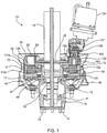
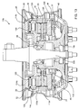
- an embodiment of the present invention comprises a number of interacting components and assemblies including a housing assembly 12 and brake callipers 14.
- the housing assembly 12 forms a liquid tight seal between an axle housing 16 and a wheel hub 18 to enclose and retain a volume of lubricant (not shown) for the wet disc brake system 10.
- a rotor 20 is splined onto and thus rotates with the hub 18.
- the rotor 20 is lubricated by the lubricant as it rotates within the housing 12 and brake callipers 14.
- a portion of the brake callipers 14, and in particular cylinders 22 of the brake callipers 14, extend into and are seated in openings 24 formed in the housing assembly 12.
- O rings 26 are provided in the opening 24 to form a seal between the housing assembly 12 and the cylinders 22.
- Seating the cylinders 22 in the openings 24 enables coupling to mechanical, hydraulic or pneumatic actuators for operating the callipers 14.
- the callipers 14 are coupled to a structural component in the form of flange 28 extending about the axle housing 16. Accordingly reactive forces created during a braking operation are transmitted via the callipers 14 to the flange 28 and axle housing 16 rather than being born by the housing assembly 12. This enables the housing assembly 12 to be made of a relatively light weight construction and/or materials such as aluminium because housing assembly 12 that bears minimal load.
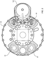
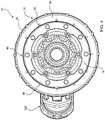
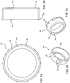
- the housing assembly 12 comprises an outer casing 30 shown in Figures 1 and 5a - 5d which extends circumferentially about the callipers 14; an inner plate 32 shown in Figures 6a - 6d and a seal carrier in the form of a second plate 34 shown in Figures 1 , 7a and 7b .
- the outer casing 30 comprises a circumferential wall 36 of constant inner diameter and provided, on an outside surface near one end 38, with a plurality of axially extending spaced apart and integrally formed ribs 40.
- the ribs 40 provide additional strength and thickness to the wall 36 for forming tapped holes to enable fastening of the inner plate 34.
- An opposite end 42 of the outer casing 30 is formed with a inwardly directed circumferential lip 44.
- the second plate 32 is fastened to the outer casing 30 by screws 46 ( Figs 1 , 3 , 4 ) that pass through the lip 44.
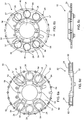
- the inner plate 32 is provided with a central opening 48 through which an axle housing 16 extends and which aids to centralise the brake housing relative to the hole 18.
- a fixing ring 52 Surrounding the opening 48 is a fixing ring 52 by which the inner plate 32 and indeed the housing assembly 12 is coupled to the flange 28 on the axle housing 16.
- the fixing ring is provided with a plurality of holes 54 that register with holes formed in the brake callipers 14 as well as holes in the flange 28 enabling attachment of the callipers 14 to the flange 28.
- Further holes 56 are provided in the fixing ring 52 to couple the inner plate 32 to the flange 28.
- Additional smaller diameter holes 57 are formed in the fixing ring 52 to attach the inner plate 32 to the callipers 14.
- the inner plate 32 is formed with a portion 58 radially outward of the fixing ring 52 in which is formed the openings 24 for the calliper cylinders 22.
- the openings 24 are, in this embodiment, arranged in two banks 62 each comprising three openings 24.
- the banks 62 are raised in relation to the portion 58 of the inner plate 32.
- the centres of the two end openings 24 in each bank 62 are separated by approximately 66°.
- a plurality of bosses 64 is formed about the outer circumferential surface of the inner plate 32 which align with the ribs 40 on the outer casing 30.
- the bosses 64 are formed with holes for receiving screws to fasten the inner plate 32 to the outer casing 30.
- the second plate 34 is in the general form of an annular plate having: a central opening 68 through which fits the hub 18; and, an outer circumferential edge 70.
- the outer edge 70 has a diameter greater than the diameter of the lip 44 on the outer casing 30.
- annular band 78 Radially inward of the seat 74 there is a right angle circumferential shoulder 76 which forms one edge of annular band 78.
- the band 78 is provided with a plurality of blind holes 80 for threadingly engage the screws 46 which fasten the plate 34 to the lip 44 of the outer casing 30.
- a radial inner edge of the band 78 is delimited by an annular shoulder 82 that projects in the axial direction from the face 72.
- the lip 44 sits inside of and abuts the shoulder 82.
- Radially inward from the shoulder 82 the face 72 is provided with an inner circumferential band 84 having blind holes 86 to facilitate the attachment of a flange seal support 88 (shown in Figure 1 ).
- the plate 34 also comprises an axially projecting boss 89 having an inner circumferential surface 90 adjacent the inner band 84 which comprises a first portion 92 of constant diameter, a contiguous second portion 94 of progressively decreasing diameter, and a contiguous third portion 96 of constant diameter. Extending radially inward from the portion 94 is a circumferential lip 98. The inner diameter of the lip 98 defines the opening 68.
- a cassette seal 100 (see Figure 1 ) is seated in the third portion 96 to form a rotary seal between the housing assembly 12 and an outer surface of the hub 18.
- a gasket seal 102 ( Fig 1 ) is disposed between the cassette seal 100 and the lip 98.
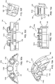
- Embodiments of the wet brake system 10 incorporate three similar but different brake callipers. These comprise a service/park brake calliper 14a shown in Figures 8a - 8f ; a two piston brake calliper 14b shown in Figures 9a - 9f ; and a three piston calliper 14c shown in Figures 10a - 10f .
- the park/service brake calliper 14a comprises an inner shell 104 and outer shell 106 which are coupled together to define a cavity 108 in which the rotor 20 rotates and which houses opposing brake pads 110a and 110b (shown in Figure 1 ).
- the cavity 108 opens onto an outer circumferential surface 109 of the calliper 14a forming a central gap 111 between the shells 104 and 106.
- the brake pad 110a is seated in a recess 112 formed on an inside of the outer shell 106.
- the inner shell 104 is formed with three cylinders 114a, 114b and 114c (hereinafter referred to in general as "cylinders 114"). Each of the cylinders 114a and 114c is provided with holes 118 to allow connection to hoses providing hydraulic fluid to respective service brake pistons 120 retained in the cylinders 114a and 114c. Extending transversely between the holes 118 on each cylinder 114a and 114c is a land 122 to facilitate connection of a spring canister 124 (shown in Figure 1 ). The spring canister is pneumatically operated to provide the park brake aspect of the service/park brake calliper 114a.
- reaction plate 126 Seated on the inside of the outer shell 104 is a reaction plate 126 (shown in Fig 1 ) which is in the form of a steel plate of a shape and configuration similar to the brake pad 110a.
- the reaction plate 126 extends across each of the pistons 120 held in the cylinders 114a and 114c as well as a park brake piston 128 (shown in Figures 1 and 12a - 12e ) disposed within the cylinder 114b.
- the inner and outer shells 104 and 106 are coupled together by sets of bolts 130 that extend from the shell 104 to the shell 106 and from the.shell 106 into the shell 102.
- the bolts 130 are located near the ends of the shells 104 and 106 on the side of the service brake cylinders 114a and 114c distant the cylinder 114b.
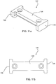
- metal straps 132 bridge the cavity 108 and are coupled to both of the shells 104 and 106 to provide bracing to the calliper 14a.
- the straps 132 are provided one on each side of the cylinder 114b.
- Each strap 132 is in the general shape of a "I" having a central column 134 and cross members 136 at opposite ends.
- the cross members 136 locate in complimentary shaped recesses formed in the inner and outer shells 104 and 106 with the cross members 136 sitting flush with outer axial faces of the shells 104 and 106.
- Bolts 140 fix the straps 132 to the shells 104 and 106.
- a mounting flange 142 is formed integrally with the inner shell 104 to facilitate attachment of the calliper 14a to the flange 28 on the axle housing 16. To this end the mounting flange 142 is provided with holes 144 and 145 that register with the holes 54 and 57 respectively in the fixing ring 52 of the inner plate 32.
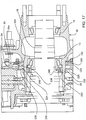
- the park brake piston 128 (see Figures 1 , 8a, 8c, 8d and 12a - 12e ) is housed within the cylinder 114b and is acted upon by the spring canister 124 via a wear compensating mechanism 146 which includes a rod 147 (see Figure 1 ).
- One end 148 of the piston 128 is formed with an axially projecting ring 150.
- the piston 128 is provided with a radial face 152 which is formed with a central raised land 154.
- a slot 156 extends axially on the piston 128 from the ring 150 to a distance approximately one third of the way toward an opposite end 158 of the park piston 128.
- a circumferential groove 160 is formed about the park piston 128 between the slot 156 and the end 158 for seating an O-ring 162 (shown in Figure 1 ).
- the slot 156 accommodates a pin 163 which extends from a face 164 of the rod 147.
- the face 164 abuts the raised land 154 and is located within the ring 150 of the piston 128.
- the land 154 provides a pivot between the rod 147 and the interface piston 128. This provides a means of self-alignment between the rod 147 and the piston 128, allowing lateral movement or rocking at the face due to: the length of the rod 147; and, the mechanism 146 which multiplies the force of the canister 124 comprising a pivoted lever arrangement.
- Wear of the brake pads 110a and 110b is compensated for in relation to application of the park brake by the mechanism 146 which causes a housing of the rod 147 to rotate about a longitudinal axis of the rod 147 as the rod 147 is advanced linearly by application of force by the spring canister 124. This rotation maintains the rod 147 in a linearly advanced position relative to its position prior to application of force by the spring canister 124 to provide wear compensation.
- the two piston calliper 14b is shown in Figures 9a - 9f .
- Each feature of the calliper 14b which is identical to corresponding features of the calliper 14a is denoted with the same reference number.
- the calliper 14b differs from the calliper 14a in the following two aspects. Firstly, the central cylinder 114b in the calliper 14b is closed and does not house any piston. Thus, braking force is applied only via the pistons 120 in the cylinders 114a and 114c. Secondly, as the calliper 14b does not have a park brake function, it does not require and therefore does not have the lands 122 depicted on the calliper 14a for mounting of the spring canister 124. In the embodiment of the braking system 10 shown in Figures 1 - 4 , one piston calliper 14b is used together with a service/park brake calliper 14a to form a rear brake assembly for braking a wheel coupled to the hub 18.
- Figures 10a - 10f depict the three piston calliper 14c.
- the three piston calliper 14c differs from the calliper 14b by the provision of a service piston 120 in the central cylinder 114b and the provision of holes 118 in the cylinder 116 to allow the application of hydraulic pressure to the piston 120.
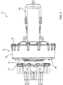
- Figure 13 depicts an embodiment of the wet disc brake system 10b comprising a housing assembly 12 and two of the three piston callipers 14c held within the housing assembly 12 to brake a rotor 20 mounted on a wheel hub 18b.
- the wheel hub 18b mounted on a stub axle 50b. the callipers 14c and thus the wet disc brake system 10b provides service brakes only with no park (or emergency) braking facility.
- Figure 14 depicts a garbage truck 170 having a receptacle 172 for holding and transporting waste matter, and mounted on a chassis having a single front axle and a tandem rear axle.
- the truck 170 in its original form is provided with drum brakes on each of the hubs on each of the axles.
- the brakes are pneumatically operated.
- the truck 170 is provided with an air compressor (not shown) for activating the brakes.
- Embodiments of the wet disc brake system 10 may be retrofitted to the truck 170 by first removing the original equipment hubs and drum brakes and retrofitting embodiments of the wet disc brake system.
- a wet disc brake system 10b as shown in Figure 13 comprising two callipers 14b with a hub 18b may be fitted on the front axles of the truck 170.
- a wet disc brake system 10 shown in Figures 1 - 4 each provided with a service/park brake calliper 14a and a two piston service brake calliper 14b with a hub 18 can be fitted.
- one or more air over hydraulic actuators (not shown) is provided between the air compressor and the cylinders of callipers that house the service brake pistons 120.
- the parking brake facility provided by the service/park brake calliper 14a is a spring applied air release park brake.
- the supply of compressed air to the canister 124 operates against the spring within the canister to release the park brake.
- the spring within the canister 124 is released so that the bias of the spring is applied through the rod 146 to the park piston 144 to apply the park brake.
- FIG. 1 Due to the configuration of the wet brake system 10, complete brake and hub assemblies for any axle can be preassembled on a work bench and coupled as a single unit to the axle.
- This assembly comprises a service and park brake calliper 14a, a two piston service brake calliper 14b.
- the callipers 14a and 14b are first assembled with the spring canister 124 and associated wear compensating rod system 145 not being attached to the calliper 14a.
- the rotor 20 is then placed centrally between the callipers with a portion of the rotor extending between the brake pads 110a and 110b in each of the callipers 14a and 14b.
- the seals 102 and 100 are seated in the seal carrier / second plate 34.
- the second plate 34 is passed into the outer casing 30 from the end 38 so as to abut with the inside of the lip 44.
- the outer casing 30 and second plate 34 are connected together by screws that pass through the lip 44 into the holes 80 in the band 78 of the plate 34.
- the hub 18 is now inserted into the opening 68 of plate 34.
- the inner plate 32 is located over the callipers 14a and 14b so that the cylinders of the callipers pass through the openings 24. O-rings 26 seal the cylinder of each of the carriers 14a and 14b to the inner plate 32.
- Screws which extend through holes 57 into holes 157 connect the inner plate 32 to the callipers 14a and 14b, with the rotor 20 retained within and between the callipers 14a and 14b.
- the seals 102 and 100 are seated in the plate 34 and the callipers 14a and 14b which are attached to the plate 32 are now lowered into the outer casing 30 with the rotor 20 orientated to slide onto splines on the hub 18.
- the inner plate 32 is now fastened to the outer casing 30.
- the entire assembly comprising the callipers 14a and 14b held within the housing 12, and the hub 18 can now be fitted onto an axle assembly.
- the hub 18 is allowed to rotate on the axle housing 16 via two tapered roller bearings 11, 13 (see Figure 1 ) which are seated on the axle housing 16.
- Axle shaft 50 which extends through the axle housing is attended to the face of the hub 18 by axle studs 15.
- the wet disc brake assembly is attached to the flange 28 on the axle housing using bolts that pass through the holes 54 and threadingly engage with holes 144 in the mounting flange 142 of the callipers 14a and 14b.
- load applied during a braking operation on the callipers 14a and 14b is transferred via the fasteners to the flange 28 and axle housing 16 rather than being born by the housing assembly 12.
- hydraulic hoses can be coupled to the cylinders 22 of the callipers 14a and 14b and the canister 124 connected with the calliper 14a.
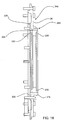
- Figures 15a-15d illustrate an inner plate 32a of a further embodiment of a wet brake system 10.
- the inner plate 32a differs from the inner plate 32 depicted in Figures 6a-6d by the provision of a finned sump 180 which protrudes in an axial direction away from the seal carrier or second plate 34.
- the purpose of the sump 180 is to increase the volume of lubricating oil inside the brake without increasing the level of the oil.
- the sump 180 lies substantially below the level of the O-ring seals 26 provided in the openings 24 which seat the calliper cylinders 22. Thus the positioning of the sump 180 reduces the likelihood of lubricant leakage about the seals.
- the sump 180 is also provided with a plurality of cooling fins 182 to an outside surface of the inner plate 32.
- the sump 180 and the fins 182 may be dimensioned to protrude beyond the wheel and rims associated with the braking system to increase heat rejection from the braking system 10.
- a sump fill the hole 184 and sump drainage hole 186 is formed on the outside of the inner plate 32a to allow filling and drainage of the sump 182.
- the holes 184 and 186 may be closed by conventional plugs.
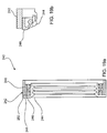
- the brake system 10 may also incorporate a cooling system 200 depicted in Figure 16 for cooling the lubricant sealed within housing assembly 12 used for lubricating the rotor 20.
- Cooling system 200 comprises a oil cooling circuit 202 comprising an oil filter 204, oil cooler 206, and pump 208, which are connected in series by a conduit 210 which provides a closed loop with housing 12.
- Conduit 210 is connected at an outlet 212 in a lower portion of housing 12 and returns via an inlet 214 at a spaced apart location in an upper region of housing 212.
- Air cooler 206 may be an air cooler similar to a radiator.
- each brake system 10 will include a separate fluid circuit although the conduit for each circuit may pass through a common oil cooler 206 in a manner where the fluid for each brake system 10 is kept separate.
- the order of the filter 204, oil cooler 206 and pump 208 in the circuit 202 is of no significance and may change or be varied to suit the chassis and structure of the vehicle to which the brake system 10 is fitted.
- the systems 10 and 10b illustrated and described each comprise two callipers disposed within the housing assembly 12.
- the braking system may comprise only a single calliper 14a, 14b or 14c.
- the braking system 10 incorporates two or more callipers; a different combination of callipers to those illustrated may be used.
- the braking system may comprise a service/park brake calliper 14a together with a three piston calliper 14c.
- An alternate braking system may comprise two two piston callipers 14b; in a further variation for larger or heavier vehicles, three or four callipers may be used in a braking system.
- callipers 14 are described as comprising two shells 104 and 106 which are coupled together. However, in alternate embodiments the callipers may be made as a single or unitary piece. Further, while Figure 14 illustrates an embodiment of the invention applied to a garbage truck, embodiments of the invention can be applied to other heavy vehicles such as buses and mining trucks.
- FIGS 17 to19b depict further modifications or variations to the system 10. These variations comprise a modified second plate 34a; the provision of a V-seal 230 about hub 18, and, the inclusion of a wheel bearing seal 240 which forms a seal between an inside of the hub 18 and the axle housing 16.
- a modified second plate 34a the provision of a V-seal 230 about hub 18, and, the inclusion of a wheel bearing seal 240 which forms a seal between an inside of the hub 18 and the axle housing 16.
- the second plate 34a which is also shown in Figure 18 , differs from the plate 34 of the first embodiment by the inclusion of an insert seal carrier 222. That is, plate 34a in essence comprises plate 34 with insert seal carrier 222 Insert seal carrier 222 is in the form of a ring having a cylindrical wall 224 which is coaxial with central opening 68 of plate 34 and flanges 226 and 228 at opposite axial ends of cylindrical wall 224. Flange 226 extends in a radial outward direction and overlies the circumferential band 84 while flange 228 extends in a radial inward direction toward an outer circumferential surface of hub 18. The outer diameter of cylindrical wall 224 is smaller than the inner diameter of boss 89 to provide a degree of play between plate 34 and carrier 222.
- Cassette seal 100 is seated within the inner circumferential surface of insert seal carrier 222.
- the degree of play between insert seal carrier 222 and plate 34 enables adjustment for any misalignment between cassette seal 100 and the outer surface of hub 18 during assembly. Minimising or eliminating misalignment extends the life of a seal substantially.
- holes in the flange 226 to enable coupling of the insert 222 to the plate 34 are slightly oversize for the fastener used.
- the fasteners used to attach insert 222 to plate 34 are initially loosened to enable adjustment for any misalignment. Once the seal cassette 100 and hub 18 have been properly aligned, the fastener may then be tightened.
- V-seal 230 is seated in a shallow circumferential groove 232 machined about the outer circumferential surface of hub 18 and located so that the V seal 230 bears against flange 228 of the insert seal carrier 222. V-seal 230 rotates with hub 18 and acts as a "flinger" for the lubricant within system 10 as well as preventing the lubricant from reaching the main housing seal.
- the double lip wheel bearing seal 240 creates a fluid seal to prevent communication between the lubricant used in wet brake system 10, and diff oil used for lubricating the hub wheel bearings 11 and 13.
- the seal 240 comprises an outer hub seal 242 which is pressed into a seat formed on an inner circumferential surface of hub 18, and an inner hub seal 244 that is pressed onto a seat formed on the axle housing 16.
- Two lip seals 246 are installed back to back between the outer hub seal 242 and inner hub seal 244.
- Inner hub seal 244 is provided with a radially extending flange 248 which extends across an axial end of the outer hub seal 242.
- a wear ring 250 which may be made for example from PTFE is located between the flange 248 and adjacent axial end of outer hub seal 242.
- the first plate 32 may be formed integrally with the outer casing 30.
- the openings 24 formed in housing assembly 12 and in particular plate 32 may be formed with axially extending circumferential walls about which seals such as boot seals may be attached to prevent the leakage of lubricant from within the system 10 and/or prevent ingress of foreign matter into system 10.
- Such boots if used will also be provided with sealed openings to allow hydraulic hoses to pass therethrough to supply the callipers with hydraulic fluid for operating the calliper pistons 120. In the event that the boots or other external seals are used, it may be possible to dispense with the O-rings 26.
Landscapes
- Engineering & Computer Science (AREA)
- General Engineering & Computer Science (AREA)
- Mechanical Engineering (AREA)
- Braking Arrangements (AREA)
Applications Claiming Priority (2)
| Application Number | Priority Date | Filing Date | Title |
|---|---|---|---|
| AU2009905982A AU2009905982A0 (en) | 2009-12-08 | Wet Disc Brake System | |
| PCT/AU2010/001653 WO2011069194A1 (en) | 2009-12-08 | 2010-12-08 | Wet disc brake system |
Publications (3)
| Publication Number | Publication Date |
|---|---|
| EP2510254A1 EP2510254A1 (en) | 2012-10-17 |
| EP2510254A4 EP2510254A4 (en) | 2018-02-28 |
| EP2510254B1 true EP2510254B1 (en) | 2021-03-10 |
Family
ID=42634685
Family Applications (1)
| Application Number | Title | Priority Date | Filing Date |
|---|---|---|---|
| EP10835294.9A Active EP2510254B1 (en) | 2009-12-08 | 2010-12-08 | Wet disc brake system |
Country Status (11)
| Country | Link |
|---|---|
| US (1) | US8800727B2 (enExample) |
| EP (1) | EP2510254B1 (enExample) |
| JP (1) | JP5819844B2 (enExample) |
| CN (1) | CN102782354B (enExample) |
| AU (2) | AU2010100626A4 (enExample) |
| BR (1) | BR112012013829B1 (enExample) |
| CA (1) | CA2783617C (enExample) |
| ES (1) | ES2874951T3 (enExample) |
| MX (1) | MX2012006632A (enExample) |
| PH (1) | PH12012501174A1 (enExample) |
| WO (1) | WO2011069194A1 (enExample) |
Cited By (1)
| Publication number | Priority date | Publication date | Assignee | Title |
|---|---|---|---|---|
| WO2024259254A1 (en) * | 2023-06-14 | 2024-12-19 | Husqvarna Ab | Parking brake for a lawn care vehicle |
Families Citing this family (14)
| Publication number | Priority date | Publication date | Assignee | Title |
|---|---|---|---|---|
| EP2878504A4 (en) * | 2012-07-24 | 2016-08-17 | Haisheng Qiang | BIDIRECTIONAL BRAKING METHOD FOR A DISC BRAKE AND BRAKE MECHANISM AND APPLICATIONS THEREOF |
| WO2014176629A1 (en) * | 2013-04-29 | 2014-11-06 | Advanced Braking Pty Ltd | Disc brake system |
| CN104847812B (zh) * | 2015-03-31 | 2017-08-08 | 中车戚墅堰机车车辆工艺研究所有限公司 | 一种全盘多片干式制动器 |
| CN105715702B (zh) * | 2016-04-01 | 2018-03-20 | 宁波彰星车辆有限公司 | 一种隐藏式双动碟刹 |
| CA3024763C (en) * | 2016-05-26 | 2024-05-28 | Advanced Braking Pty Ltd | Lightweight brake system |
| AU201612928S (en) * | 2016-05-31 | 2016-06-09 | Advanced Braking Pty Ltd | Brake cover plate |
| DE102018106297B4 (de) * | 2018-03-19 | 2021-05-27 | Saf-Holland Gmbh | Mehrteilige Bremstrommel |
| JP7229810B2 (ja) * | 2018-06-29 | 2023-02-28 | 株式会社アドヴィックス | ブレーキ装置 |
| CN109572634B (zh) * | 2018-12-20 | 2024-08-23 | 内蒙古北方重型汽车股份有限公司 | 机械传动矿用车干盘式后制动装置 |
| CN112572374B (zh) * | 2019-09-30 | 2022-12-30 | 新疆大道防务装备有限公司 | 一种轮边减速器总成及车轮总成 |
| CN113513549B (zh) * | 2020-04-09 | 2023-03-21 | 北京优加特福乐科技有限公司 | 一种内循环水冷制动器 |
| US12492729B2 (en) * | 2023-01-20 | 2025-12-09 | Dana Italia S.R.L. | Anti-vibration support for an external spring applied hydraulic release brake assembly |
| CN117823550B (zh) * | 2024-03-05 | 2024-05-24 | 山东欧劲工程机械有限公司 | 一种高扭矩工程车辆制动组 |
| WO2025194207A1 (en) * | 2024-03-18 | 2025-09-25 | Advanced Braking Pty Ltd | Brake calliper |
Family Cites Families (19)
| Publication number | Priority date | Publication date | Assignee | Title |
|---|---|---|---|---|
| US2981376A (en) * | 1958-01-27 | 1961-04-25 | Borg Warner | Disc brake |
| JPS604023B2 (ja) * | 1977-08-15 | 1985-02-01 | 新明和工業株式会社 | 車輌における空気圧制動装置 |
| DE2804209A1 (de) * | 1978-02-01 | 1979-08-02 | Kloeckner Humboldt Deutz Ag | Teilbelagscheibenbremse, insbesondere fuer eine getriebewelle und/oder die achsantriebswelle eines land- und/oder bauwirtschaftlich nutzbaren kraftfahrzeuges |
| US4429767A (en) * | 1980-08-25 | 1984-02-07 | Jenkins Robert L | Pelletized brake lining disc brake |
| JPH0520904Y2 (enExample) * | 1988-12-21 | 1993-05-28 | ||
| JPH0474746U (enExample) * | 1990-11-01 | 1992-06-30 | ||
| EP0607248B1 (en) * | 1991-10-11 | 1999-01-07 | PARSONS, Francis Edward | Wet disc brake |
| US5228543A (en) * | 1992-02-03 | 1993-07-20 | Power Transmission Technology, Inc. | Sealed wet disc brake for vehicles |
| JP3901329B2 (ja) * | 1998-02-10 | 2007-04-04 | 日清紡績株式会社 | ディスクブレーキ装置 |
| JP2000018290A (ja) * | 1998-06-30 | 2000-01-18 | Furukawa Co Ltd | ブレーキ装置 |
| FR2820794A1 (fr) | 2001-02-12 | 2002-08-16 | Messier Bugatti | Cinquieme frein de vehicule automobile |
| AUPR739301A0 (en) * | 2001-08-31 | 2001-09-20 | Safe Effect Pty Ltd | Brake actuator |
| JP3978084B2 (ja) * | 2002-05-29 | 2007-09-19 | 三菱重工業株式会社 | 車両用ブレーキ装置及びその組み換え方法 |
| US20060054426A1 (en) * | 2004-09-13 | 2006-03-16 | Fillmore Dale A | Braking apparatus and method of braking |
| US7493994B2 (en) * | 2004-12-16 | 2009-02-24 | Bendix Spicer Foundation Brake Llc | Spring brake actuator with mid-located spring |
| US7137488B2 (en) * | 2005-04-18 | 2006-11-21 | Warren Gilliland | Disk brake caliper having re-enforcing bridge |
| WO2007038693A2 (en) * | 2005-09-28 | 2007-04-05 | Baldwin Wilson Development Corporation | Disc brake assembly |
| JP4977141B2 (ja) * | 2005-10-05 | 2012-07-18 | フレニ・ブレンボ エス・ピー・エー | フットブレーキとパーキングブレーキを組み合せた車両用ディスク式制動装置 |
| EP1963701B1 (en) * | 2005-12-19 | 2010-05-19 | Freni Brembo S.P.A. | Disc brake caliper |
-
2010
- 2010-06-17 AU AU2010100626A patent/AU2010100626A4/en not_active Expired
- 2010-12-08 EP EP10835294.9A patent/EP2510254B1/en active Active
- 2010-12-08 BR BR112012013829-4A patent/BR112012013829B1/pt active IP Right Grant
- 2010-12-08 MX MX2012006632A patent/MX2012006632A/es not_active Application Discontinuation
- 2010-12-08 CN CN201080060576.7A patent/CN102782354B/zh active Active
- 2010-12-08 AU AU2010330682A patent/AU2010330682B2/en active Active
- 2010-12-08 CA CA2783617A patent/CA2783617C/en active Active
- 2010-12-08 WO PCT/AU2010/001653 patent/WO2011069194A1/en not_active Ceased
- 2010-12-08 ES ES10835294T patent/ES2874951T3/es active Active
- 2010-12-08 PH PH1/2012/501174A patent/PH12012501174A1/en unknown
- 2010-12-08 JP JP2012542316A patent/JP5819844B2/ja active Active
-
2012
- 2012-06-07 US US13/490,701 patent/US8800727B2/en active Active
Non-Patent Citations (1)
| Title |
|---|
| None * |
Cited By (1)
| Publication number | Priority date | Publication date | Assignee | Title |
|---|---|---|---|---|
| WO2024259254A1 (en) * | 2023-06-14 | 2024-12-19 | Husqvarna Ab | Parking brake for a lawn care vehicle |
Also Published As
| Publication number | Publication date |
|---|---|
| CN102782354A (zh) | 2012-11-14 |
| BR112012013829B1 (pt) | 2021-05-18 |
| JP5819844B2 (ja) | 2015-11-24 |
| WO2011069194A1 (en) | 2011-06-16 |
| AU2010100626A4 (en) | 2010-08-19 |
| PH12012501174A1 (en) | 2012-10-22 |
| US8800727B2 (en) | 2014-08-12 |
| JP2013513079A (ja) | 2013-04-18 |
| CA2783617A1 (en) | 2011-06-16 |
| EP2510254A4 (en) | 2018-02-28 |
| BR112012013829A2 (pt) | 2018-05-29 |
| EP2510254A1 (en) | 2012-10-17 |
| CN102782354B (zh) | 2016-01-20 |
| ES2874951T3 (es) | 2021-11-05 |
| AU2010330682B2 (en) | 2015-08-20 |
| CA2783617C (en) | 2017-12-05 |
| US20120318622A1 (en) | 2012-12-20 |
| AU2010330682A1 (en) | 2012-07-12 |
| MX2012006632A (es) | 2012-11-30 |
Similar Documents
| Publication | Publication Date | Title |
|---|---|---|
| EP2510254B1 (en) | Wet disc brake system | |
| EP1610025B1 (en) | Method of operating a disc brake assembly | |
| KR102936934B1 (ko) | 드럼 브레이크 | |
| US3081843A (en) | Improvement in caliper type disk brakes | |
| US3999635A (en) | Disc brake caliper and lining carrier supporting means | |
| US10746242B2 (en) | Disc brake | |
| EP1596092A1 (en) | Brake pad wear indicator | |
| EP1105658B1 (en) | Multiple disk brake system with integrated parking brake | |
| US3780834A (en) | Disc brake assembly | |
| US3478844A (en) | Fixed-yoke disk brake | |
| US6257378B1 (en) | Caliper for disc brake assembly | |
| US2915147A (en) | Disc brake for vehicles | |
| US6550588B2 (en) | Off highway truck brake assembly and wheel spindle having a spline joint | |
| US20090095581A1 (en) | Floating disc brake | |
| CA1059042A (en) | Disc brake | |
| EP0096498B1 (en) | A disc brake and disc brake pad | |
| US3289793A (en) | Sealed brake | |
| WO2014176629A1 (en) | Disc brake system | |
| JPS63306956A (ja) | パ−キングブレ−キ付流体式リタ−ダ |
Legal Events
| Date | Code | Title | Description |
|---|---|---|---|
| PUAI | Public reference made under article 153(3) epc to a published international application that has entered the european phase |
Free format text: ORIGINAL CODE: 0009012 |
|
| 17P | Request for examination filed |
Effective date: 20120704 |
|
| AK | Designated contracting states |
Kind code of ref document: A1 Designated state(s): AL AT BE BG CH CY CZ DE DK EE ES FI FR GB GR HR HU IE IS IT LI LT LU LV MC MK MT NL NO PL PT RO RS SE SI SK SM TR |
|
| DAX | Request for extension of the european patent (deleted) | ||
| REG | Reference to a national code |
Ref country code: DE Ref legal event code: R079 Ref document number: 602010066588 Country of ref document: DE Free format text: PREVIOUS MAIN CLASS: F16D0055226000 Ipc: F16D0055320000 |
|
| RA4 | Supplementary search report drawn up and despatched (corrected) |
Effective date: 20180125 |
|
| RIC1 | Information provided on ipc code assigned before grant |
Ipc: B60T 13/12 20060101ALI20180119BHEP Ipc: F16D 55/32 20060101AFI20180119BHEP Ipc: B60T 13/38 20060101ALI20180119BHEP Ipc: F16D 65/853 20060101ALI20180119BHEP |
|
| STAA | Information on the status of an ep patent application or granted ep patent |
Free format text: STATUS: EXAMINATION IS IN PROGRESS |
|
| 17Q | First examination report despatched |
Effective date: 20191121 |
|
| GRAP | Despatch of communication of intention to grant a patent |
Free format text: ORIGINAL CODE: EPIDOSNIGR1 |
|
| STAA | Information on the status of an ep patent application or granted ep patent |
Free format text: STATUS: GRANT OF PATENT IS INTENDED |
|
| INTG | Intention to grant announced |
Effective date: 20200924 |
|
| GRAS | Grant fee paid |
Free format text: ORIGINAL CODE: EPIDOSNIGR3 |
|
| GRAA | (expected) grant |
Free format text: ORIGINAL CODE: 0009210 |
|
| STAA | Information on the status of an ep patent application or granted ep patent |
Free format text: STATUS: THE PATENT HAS BEEN GRANTED |
|
| AK | Designated contracting states |
Kind code of ref document: B1 Designated state(s): AL AT BE BG CH CY CZ DE DK EE ES FI FR GB GR HR HU IE IS IT LI LT LU LV MC MK MT NL NO PL PT RO RS SE SI SK SM TR |
|
| REG | Reference to a national code |
Ref country code: GB Ref legal event code: FG4D |
|
| REG | Reference to a national code |
Ref country code: AT Ref legal event code: REF Ref document number: 1370130 Country of ref document: AT Kind code of ref document: T Effective date: 20210315 Ref country code: CH Ref legal event code: EP |
|
| REG | Reference to a national code |
Ref country code: DE Ref legal event code: R096 Ref document number: 602010066588 Country of ref document: DE |
|
| REG | Reference to a national code |
Ref country code: IE Ref legal event code: FG4D |
|
| REG | Reference to a national code |
Ref country code: LT Ref legal event code: MG9D |
|
| PG25 | Lapsed in a contracting state [announced via postgrant information from national office to epo] |
Ref country code: NO Free format text: LAPSE BECAUSE OF FAILURE TO SUBMIT A TRANSLATION OF THE DESCRIPTION OR TO PAY THE FEE WITHIN THE PRESCRIBED TIME-LIMIT Effective date: 20210610 Ref country code: BG Free format text: LAPSE BECAUSE OF FAILURE TO SUBMIT A TRANSLATION OF THE DESCRIPTION OR TO PAY THE FEE WITHIN THE PRESCRIBED TIME-LIMIT Effective date: 20210610 Ref country code: LT Free format text: LAPSE BECAUSE OF FAILURE TO SUBMIT A TRANSLATION OF THE DESCRIPTION OR TO PAY THE FEE WITHIN THE PRESCRIBED TIME-LIMIT Effective date: 20210310 Ref country code: FI Free format text: LAPSE BECAUSE OF FAILURE TO SUBMIT A TRANSLATION OF THE DESCRIPTION OR TO PAY THE FEE WITHIN THE PRESCRIBED TIME-LIMIT Effective date: 20210310 Ref country code: GR Free format text: LAPSE BECAUSE OF FAILURE TO SUBMIT A TRANSLATION OF THE DESCRIPTION OR TO PAY THE FEE WITHIN THE PRESCRIBED TIME-LIMIT Effective date: 20210611 Ref country code: HR Free format text: LAPSE BECAUSE OF FAILURE TO SUBMIT A TRANSLATION OF THE DESCRIPTION OR TO PAY THE FEE WITHIN THE PRESCRIBED TIME-LIMIT Effective date: 20210310 |
|
| REG | Reference to a national code |
Ref country code: AT Ref legal event code: MK05 Ref document number: 1370130 Country of ref document: AT Kind code of ref document: T Effective date: 20210310 |
|
| REG | Reference to a national code |
Ref country code: NL Ref legal event code: MP Effective date: 20210310 |
|
| REG | Reference to a national code |
Ref country code: DE Ref legal event code: R081 Ref document number: 602010066588 Country of ref document: DE Owner name: ADVANCED BRAKING PTY LTD, WANGARA, AU Free format text: FORMER OWNER: ADVANCED BRAKING PTY LTD, OSBORNE PARK, WA, AU |
|
| PG25 | Lapsed in a contracting state [announced via postgrant information from national office to epo] |
Ref country code: RS Free format text: LAPSE BECAUSE OF FAILURE TO SUBMIT A TRANSLATION OF THE DESCRIPTION OR TO PAY THE FEE WITHIN THE PRESCRIBED TIME-LIMIT Effective date: 20210310 Ref country code: LV Free format text: LAPSE BECAUSE OF FAILURE TO SUBMIT A TRANSLATION OF THE DESCRIPTION OR TO PAY THE FEE WITHIN THE PRESCRIBED TIME-LIMIT Effective date: 20210310 Ref country code: SE Free format text: LAPSE BECAUSE OF FAILURE TO SUBMIT A TRANSLATION OF THE DESCRIPTION OR TO PAY THE FEE WITHIN THE PRESCRIBED TIME-LIMIT Effective date: 20210310 |
|
| RAP4 | Party data changed (patent owner data changed or rights of a patent transferred) |
Owner name: ADVANCED BRAKING PTY LTD |
|
| PG25 | Lapsed in a contracting state [announced via postgrant information from national office to epo] |
Ref country code: NL Free format text: LAPSE BECAUSE OF FAILURE TO SUBMIT A TRANSLATION OF THE DESCRIPTION OR TO PAY THE FEE WITHIN THE PRESCRIBED TIME-LIMIT Effective date: 20210310 |
|
| PG25 | Lapsed in a contracting state [announced via postgrant information from national office to epo] |
Ref country code: EE Free format text: LAPSE BECAUSE OF FAILURE TO SUBMIT A TRANSLATION OF THE DESCRIPTION OR TO PAY THE FEE WITHIN THE PRESCRIBED TIME-LIMIT Effective date: 20210310 Ref country code: CZ Free format text: LAPSE BECAUSE OF FAILURE TO SUBMIT A TRANSLATION OF THE DESCRIPTION OR TO PAY THE FEE WITHIN THE PRESCRIBED TIME-LIMIT Effective date: 20210310 Ref country code: AT Free format text: LAPSE BECAUSE OF FAILURE TO SUBMIT A TRANSLATION OF THE DESCRIPTION OR TO PAY THE FEE WITHIN THE PRESCRIBED TIME-LIMIT Effective date: 20210310 Ref country code: SM Free format text: LAPSE BECAUSE OF FAILURE TO SUBMIT A TRANSLATION OF THE DESCRIPTION OR TO PAY THE FEE WITHIN THE PRESCRIBED TIME-LIMIT Effective date: 20210310 |
|
| REG | Reference to a national code |
Ref country code: ES Ref legal event code: FG2A Ref document number: 2874951 Country of ref document: ES Kind code of ref document: T3 Effective date: 20211105 |
|
| PG25 | Lapsed in a contracting state [announced via postgrant information from national office to epo] |
Ref country code: IS Free format text: LAPSE BECAUSE OF FAILURE TO SUBMIT A TRANSLATION OF THE DESCRIPTION OR TO PAY THE FEE WITHIN THE PRESCRIBED TIME-LIMIT Effective date: 20210710 Ref country code: RO Free format text: LAPSE BECAUSE OF FAILURE TO SUBMIT A TRANSLATION OF THE DESCRIPTION OR TO PAY THE FEE WITHIN THE PRESCRIBED TIME-LIMIT Effective date: 20210310 Ref country code: PL Free format text: LAPSE BECAUSE OF FAILURE TO SUBMIT A TRANSLATION OF THE DESCRIPTION OR TO PAY THE FEE WITHIN THE PRESCRIBED TIME-LIMIT Effective date: 20210310 Ref country code: PT Free format text: LAPSE BECAUSE OF FAILURE TO SUBMIT A TRANSLATION OF THE DESCRIPTION OR TO PAY THE FEE WITHIN THE PRESCRIBED TIME-LIMIT Effective date: 20210712 Ref country code: SK Free format text: LAPSE BECAUSE OF FAILURE TO SUBMIT A TRANSLATION OF THE DESCRIPTION OR TO PAY THE FEE WITHIN THE PRESCRIBED TIME-LIMIT Effective date: 20210310 |
|
| REG | Reference to a national code |
Ref country code: DE Ref legal event code: R097 Ref document number: 602010066588 Country of ref document: DE |
|
| PLBE | No opposition filed within time limit |
Free format text: ORIGINAL CODE: 0009261 |
|
| STAA | Information on the status of an ep patent application or granted ep patent |
Free format text: STATUS: NO OPPOSITION FILED WITHIN TIME LIMIT |
|
| PG25 | Lapsed in a contracting state [announced via postgrant information from national office to epo] |
Ref country code: DK Free format text: LAPSE BECAUSE OF FAILURE TO SUBMIT A TRANSLATION OF THE DESCRIPTION OR TO PAY THE FEE WITHIN THE PRESCRIBED TIME-LIMIT Effective date: 20210310 Ref country code: AL Free format text: LAPSE BECAUSE OF FAILURE TO SUBMIT A TRANSLATION OF THE DESCRIPTION OR TO PAY THE FEE WITHIN THE PRESCRIBED TIME-LIMIT Effective date: 20210310 |
|
| 26N | No opposition filed |
Effective date: 20211213 |
|
| PG25 | Lapsed in a contracting state [announced via postgrant information from national office to epo] |
Ref country code: SI Free format text: LAPSE BECAUSE OF FAILURE TO SUBMIT A TRANSLATION OF THE DESCRIPTION OR TO PAY THE FEE WITHIN THE PRESCRIBED TIME-LIMIT Effective date: 20210310 |
|
| PG25 | Lapsed in a contracting state [announced via postgrant information from national office to epo] |
Ref country code: IS Free format text: LAPSE BECAUSE OF FAILURE TO SUBMIT A TRANSLATION OF THE DESCRIPTION OR TO PAY THE FEE WITHIN THE PRESCRIBED TIME-LIMIT Effective date: 20210710 |
|
| PG25 | Lapsed in a contracting state [announced via postgrant information from national office to epo] |
Ref country code: MC Free format text: LAPSE BECAUSE OF FAILURE TO SUBMIT A TRANSLATION OF THE DESCRIPTION OR TO PAY THE FEE WITHIN THE PRESCRIBED TIME-LIMIT Effective date: 20210310 |
|
| REG | Reference to a national code |
Ref country code: BE Ref legal event code: MM Effective date: 20211231 |
|
| PG25 | Lapsed in a contracting state [announced via postgrant information from national office to epo] |
Ref country code: LU Free format text: LAPSE BECAUSE OF NON-PAYMENT OF DUE FEES Effective date: 20211208 Ref country code: IE Free format text: LAPSE BECAUSE OF NON-PAYMENT OF DUE FEES Effective date: 20211208 |
|
| PG25 | Lapsed in a contracting state [announced via postgrant information from national office to epo] |
Ref country code: BE Free format text: LAPSE BECAUSE OF NON-PAYMENT OF DUE FEES Effective date: 20211231 |
|
| PG25 | Lapsed in a contracting state [announced via postgrant information from national office to epo] |
Ref country code: HU Free format text: LAPSE BECAUSE OF FAILURE TO SUBMIT A TRANSLATION OF THE DESCRIPTION OR TO PAY THE FEE WITHIN THE PRESCRIBED TIME-LIMIT; INVALID AB INITIO Effective date: 20101208 Ref country code: CY Free format text: LAPSE BECAUSE OF FAILURE TO SUBMIT A TRANSLATION OF THE DESCRIPTION OR TO PAY THE FEE WITHIN THE PRESCRIBED TIME-LIMIT Effective date: 20210310 |
|
| PG25 | Lapsed in a contracting state [announced via postgrant information from national office to epo] |
Ref country code: MK Free format text: LAPSE BECAUSE OF FAILURE TO SUBMIT A TRANSLATION OF THE DESCRIPTION OR TO PAY THE FEE WITHIN THE PRESCRIBED TIME-LIMIT Effective date: 20210310 |
|
| PG25 | Lapsed in a contracting state [announced via postgrant information from national office to epo] |
Ref country code: MT Free format text: LAPSE BECAUSE OF FAILURE TO SUBMIT A TRANSLATION OF THE DESCRIPTION OR TO PAY THE FEE WITHIN THE PRESCRIBED TIME-LIMIT Effective date: 20210310 |
|
| PG25 | Lapsed in a contracting state [announced via postgrant information from national office to epo] |
Ref country code: TR Free format text: LAPSE BECAUSE OF FAILURE TO SUBMIT A TRANSLATION OF THE DESCRIPTION OR TO PAY THE FEE WITHIN THE PRESCRIBED TIME-LIMIT Effective date: 20210310 |
|
| REG | Reference to a national code |
Ref country code: CH Ref legal event code: U11 Free format text: ST27 STATUS EVENT CODE: U-0-0-U10-U11 (AS PROVIDED BY THE NATIONAL OFFICE) Effective date: 20260101 |
|
| PGFP | Annual fee paid to national office [announced via postgrant information from national office to epo] |
Ref country code: DE Payment date: 20251211 Year of fee payment: 16 |
|
| PGFP | Annual fee paid to national office [announced via postgrant information from national office to epo] |
Ref country code: GB Payment date: 20251219 Year of fee payment: 16 |
|
| PGFP | Annual fee paid to national office [announced via postgrant information from national office to epo] |
Ref country code: IT Payment date: 20251223 Year of fee payment: 16 |
|
| PGFP | Annual fee paid to national office [announced via postgrant information from national office to epo] |
Ref country code: FR Payment date: 20251222 Year of fee payment: 16 |
|
| PGFP | Annual fee paid to national office [announced via postgrant information from national office to epo] |
Ref country code: ES Payment date: 20260130 Year of fee payment: 16 |
|
| PGFP | Annual fee paid to national office [announced via postgrant information from national office to epo] |
Ref country code: CH Payment date: 20260101 Year of fee payment: 16 |