EP2509839B1 - Verfahren und vorrichtung zur steuerung eines fahrzeugs an ein objekt während eines einparkvorgangs - Google Patents
Verfahren und vorrichtung zur steuerung eines fahrzeugs an ein objekt während eines einparkvorgangs Download PDFInfo
- Publication number
- EP2509839B1 EP2509839B1 EP10779475.2A EP10779475A EP2509839B1 EP 2509839 B1 EP2509839 B1 EP 2509839B1 EP 10779475 A EP10779475 A EP 10779475A EP 2509839 B1 EP2509839 B1 EP 2509839B1
- Authority
- EP
- European Patent Office
- Prior art keywords
- vehicle
- distance
- speed
- parking
- clutch
- Prior art date
- Legal status (The legal status is an assumption and is not a legal conclusion. Google has not performed a legal analysis and makes no representation as to the accuracy of the status listed.)
- Active
Links
- 238000000034 method Methods 0.000 title claims description 18
- 230000008569 process Effects 0.000 claims description 10
- 230000005540 biological transmission Effects 0.000 description 23
- 238000013459 approach Methods 0.000 description 13
- 230000008859 change Effects 0.000 description 2
- 238000002485 combustion reaction Methods 0.000 description 2
- 230000001419 dependent effect Effects 0.000 description 2
- 230000003213 activating effect Effects 0.000 description 1
- 230000008901 benefit Effects 0.000 description 1
- 230000008878 coupling Effects 0.000 description 1
- 238000010168 coupling process Methods 0.000 description 1
- 238000005859 coupling reaction Methods 0.000 description 1
- 230000000881 depressing effect Effects 0.000 description 1
- 238000011156 evaluation Methods 0.000 description 1
- 230000006870 function Effects 0.000 description 1
- 230000000977 initiatory effect Effects 0.000 description 1
- 230000003287 optical effect Effects 0.000 description 1
Images

Classifications
-
- B—PERFORMING OPERATIONS; TRANSPORTING
- B60—VEHICLES IN GENERAL
- B60W—CONJOINT CONTROL OF VEHICLE SUB-UNITS OF DIFFERENT TYPE OR DIFFERENT FUNCTION; CONTROL SYSTEMS SPECIALLY ADAPTED FOR HYBRID VEHICLES; ROAD VEHICLE DRIVE CONTROL SYSTEMS FOR PURPOSES NOT RELATED TO THE CONTROL OF A PARTICULAR SUB-UNIT
- B60W10/00—Conjoint control of vehicle sub-units of different type or different function
- B60W10/04—Conjoint control of vehicle sub-units of different type or different function including control of propulsion units
- B60W10/06—Conjoint control of vehicle sub-units of different type or different function including control of propulsion units including control of combustion engines
-
- B—PERFORMING OPERATIONS; TRANSPORTING
- B60—VEHICLES IN GENERAL
- B60W—CONJOINT CONTROL OF VEHICLE SUB-UNITS OF DIFFERENT TYPE OR DIFFERENT FUNCTION; CONTROL SYSTEMS SPECIALLY ADAPTED FOR HYBRID VEHICLES; ROAD VEHICLE DRIVE CONTROL SYSTEMS FOR PURPOSES NOT RELATED TO THE CONTROL OF A PARTICULAR SUB-UNIT
- B60W10/00—Conjoint control of vehicle sub-units of different type or different function
- B60W10/02—Conjoint control of vehicle sub-units of different type or different function including control of driveline clutches
-
- B—PERFORMING OPERATIONS; TRANSPORTING
- B60—VEHICLES IN GENERAL
- B60W—CONJOINT CONTROL OF VEHICLE SUB-UNITS OF DIFFERENT TYPE OR DIFFERENT FUNCTION; CONTROL SYSTEMS SPECIALLY ADAPTED FOR HYBRID VEHICLES; ROAD VEHICLE DRIVE CONTROL SYSTEMS FOR PURPOSES NOT RELATED TO THE CONTROL OF A PARTICULAR SUB-UNIT
- B60W10/00—Conjoint control of vehicle sub-units of different type or different function
- B60W10/04—Conjoint control of vehicle sub-units of different type or different function including control of propulsion units
- B60W10/08—Conjoint control of vehicle sub-units of different type or different function including control of propulsion units including control of electric propulsion units, e.g. motors or generators
-
- B—PERFORMING OPERATIONS; TRANSPORTING
- B60—VEHICLES IN GENERAL
- B60W—CONJOINT CONTROL OF VEHICLE SUB-UNITS OF DIFFERENT TYPE OR DIFFERENT FUNCTION; CONTROL SYSTEMS SPECIALLY ADAPTED FOR HYBRID VEHICLES; ROAD VEHICLE DRIVE CONTROL SYSTEMS FOR PURPOSES NOT RELATED TO THE CONTROL OF A PARTICULAR SUB-UNIT
- B60W10/00—Conjoint control of vehicle sub-units of different type or different function
- B60W10/10—Conjoint control of vehicle sub-units of different type or different function including control of change-speed gearings
-
- B—PERFORMING OPERATIONS; TRANSPORTING
- B60—VEHICLES IN GENERAL
- B60W—CONJOINT CONTROL OF VEHICLE SUB-UNITS OF DIFFERENT TYPE OR DIFFERENT FUNCTION; CONTROL SYSTEMS SPECIALLY ADAPTED FOR HYBRID VEHICLES; ROAD VEHICLE DRIVE CONTROL SYSTEMS FOR PURPOSES NOT RELATED TO THE CONTROL OF A PARTICULAR SUB-UNIT
- B60W10/00—Conjoint control of vehicle sub-units of different type or different function
- B60W10/18—Conjoint control of vehicle sub-units of different type or different function including control of braking systems
- B60W10/184—Conjoint control of vehicle sub-units of different type or different function including control of braking systems with wheel brakes
-
- B—PERFORMING OPERATIONS; TRANSPORTING
- B60—VEHICLES IN GENERAL
- B60W—CONJOINT CONTROL OF VEHICLE SUB-UNITS OF DIFFERENT TYPE OR DIFFERENT FUNCTION; CONTROL SYSTEMS SPECIALLY ADAPTED FOR HYBRID VEHICLES; ROAD VEHICLE DRIVE CONTROL SYSTEMS FOR PURPOSES NOT RELATED TO THE CONTROL OF A PARTICULAR SUB-UNIT
- B60W30/00—Purposes of road vehicle drive control systems not related to the control of a particular sub-unit, e.g. of systems using conjoint control of vehicle sub-units
- B60W30/18—Propelling the vehicle
- B60W30/18009—Propelling the vehicle related to particular drive situations
- B60W30/18063—Creeping
-
- B—PERFORMING OPERATIONS; TRANSPORTING
- B62—LAND VEHICLES FOR TRAVELLING OTHERWISE THAN ON RAILS
- B62D—MOTOR VEHICLES; TRAILERS
- B62D15/00—Steering not otherwise provided for
- B62D15/02—Steering position indicators ; Steering position determination; Steering aids
- B62D15/027—Parking aids, e.g. instruction means
- B62D15/0285—Parking performed automatically
-
- B—PERFORMING OPERATIONS; TRANSPORTING
- B60—VEHICLES IN GENERAL
- B60W—CONJOINT CONTROL OF VEHICLE SUB-UNITS OF DIFFERENT TYPE OR DIFFERENT FUNCTION; CONTROL SYSTEMS SPECIALLY ADAPTED FOR HYBRID VEHICLES; ROAD VEHICLE DRIVE CONTROL SYSTEMS FOR PURPOSES NOT RELATED TO THE CONTROL OF A PARTICULAR SUB-UNIT
- B60W2552/00—Input parameters relating to infrastructure
- B60W2552/15—Road slope, i.e. the inclination of a road segment in the longitudinal direction
Definitions
- the invention relates to a method for controlling the approach of a vehicle to an object according to the preamble of claim 1.
- the invention relates to a device for controlling the approach of a vehicle to an object according to the preamble of claim 7.
- a parking operation of a vehicle in particular an automatic parking process in which the driver determines the parking and the vehicle takes the longitudinal and transverse control in the parking space, it is desirable that parking spaces can be used, the length estimated for a parking difficult by the driver can be.
- the length of the parking space is also determined by the system of the vehicle for parking. For this reason, when surveying and subsequent parking a relatively large distance to at least one obstacle is selected, making parking in tight parking spaces, or until just before an object for the current systems difficult or impossible to implement.
- the object of the invention is to optimize the prior art in order to introduce a vehicle even more precisely to an object.
- the vehicle when the vehicle approaches an object, the vehicle is operated at the idling speed of the drive device, for example an internal combustion engine.
- Objects may be vehicles or other obstacles such as pillars, curbs, trees, etc.
- the use of idle speed is particularly advantageous because it does not interfere with the engine control to move the vehicle.
- this invention is particularly advantageous because when the gear is engaged, the idle speed, the vehicle at low speed, without further interference by the driver moves.
- This inventive approach to an object occurs in a first distance range to the object, e.g. when reversing to the object.
- a sensor such as e.g. an ultrasonic sensor at the rear of a vehicle, the distance to the object.
- the idle speed is known to those skilled in the art (see Kraftfahr Technisches Taschenbuch, Bosch, 22nd edition) and is determined by the fact that sensors determine the engine speed, engine temperature and throttle position. Furthermore, load conditions of, for example, an automatic transmission, an air conditioner, a power steering and other disturbances can also be detected. These factors govern the idling speed. If a vehicle is in idle speed mode and a load is switched on, this results in almost no speed drop and can be intercepted with the idle speed.
- the transmission of the engine power to the wheels is interrupted until a first distance which is less than the second distance to the object and whose end has been determined by at least one sensor and at least one control device is reached.
- This achievement of the first distance from which the interruption of the power transmission takes place according to the invention also depends on the inclination angle of the vehicle and the direction of movement of the vehicle to or against a slope. These parameters are determined by known sensors, e.g. Wheel speed sensors and / or gear position and / or tilt sensors, etc. which are known in the art, transmitted to the control device.
- the controller determines based on the speed of the vehicle at idle and said environment and sensor information the distance to the obstacle upon approach, from which a braking operation is initiated and the power transmission of the engine is interrupted on the wheels.
- the clutch e.g. the transmission clutch for the first gear or the lowest gear ratio, e.g. for the reverse, not completely closed.
- the speed of the vehicle for approaching the object is further reduced to about 1 km / h to 5 km / h, preferably 3 km / h, which is very advantageous for the exact approach to an object.
- control device controls at least one brake actuator in order to achieve active braking to a standstill in front of an obstacle.
- This has the advantage that the standstill is controlled to an obstacle exactly, and on the other hand, that the vehicle is held at a standstill in this position, in particular by the function of the electric parking brake is automatically activated when it reaches standstill, or becomes.
- the further object is immediately recognized by at least one sensor, such as the ultrasonic sensor, for example, and transmitted to the computing device, which immediately activates the braking process.
- the stopping distance to the object up to which it is to be parked is e.g. depending on a previously measured by the vehicle while driving past parking space, if it is a longitudinal or transverse parking space. After passing the driver gets the signal that a parking operation is possible. By actuating a control element of the parking process is started in the parking space.
- a low speed is achieved which is very advantageous for accurate approach to the object. Due to the decoupling of the drive device and the beginning of the braking process, the speed is further reduced to a standstill in order to achieve an exact holding distance to the obstacle. At low speed, a more accurate evaluation of the sensor signals is possible and accurate braking to a standstill.
- the control of at least one brake of the vehicle for example, via an electronic Brake control done, such as the well-known ESP system (Electronic Stability Program).
- Idle operation means, for example for a vehicle with an automatic transmission, that the vehicle has an engaged gear selector, e.g. "R” for "reverse” or “D” for “driving” moves without the driver activating the brake and / or accelerator, i. does not affect the longitudinal guidance of the vehicle.
- An intervention in the engine control is inventive for the idling operation is not necessary.
- the idling operation is operated at idle speed of the engine, which is selected so that the engine does not go off and the vehicle is still moving.
- the idling speed is in the range of about 800 U / min to about 1500 U / min.
- idling speed means the range at which the vehicle with automatic transmission moves in the speed range of about 1km / h to 10km / h without the driver actively entering the longitudinal guide intervenes.
- the vehicle In a manual transmission vehicle, the vehicle is moved forward at idle speed in first gear, or reverse gear during reverse travel, without the vehicle driver actively depressing the brake pedal and / or accelerator pedal.
- an actuator which is controlled by the invention, the clutch is opened for power transmission when reaching a second distance to the obstacle.
- the driver instead of the control of the actuator, the driver receives information that is optical and / or audible, and signals him to actuate the clutch.
- the invention allows by utilizing the idle speed a particularly energy-efficient use of the vehicle and low speed, an exact approach to the obstacle to a standstill.
- the actuator can be designed so that a grinding of the clutch is also made possible here.
- the approach to an object is initiated by actuating a control element and / or voice control.
- Particularly inventive is the device for controlling a vehicle to an object, wherein a drive means moves the vehicle, a braking device decelerates the vehicle, at least one sensor detects the distance to the object and at least one control device receives the data, evaluates and outputs corresponding control signals.
- the inventive device brings the vehicle by means of the drive means to a speed which corresponds at most to the drive speed at idle speed.
- the drive device keeps the speed up to a first distance and the braking device brakes the vehicle to a second distance, which corresponds to the holding distance, to a standstill.
- FIG. 1 shows an exemplary parking operation according to the invention.
- the vehicle 1 takes the parking space between these two objects 2 and 3 by means of laterally directed ultrasonic sensors and signals to the driver of the vehicle 1 that a parking operation is possible.
- a parking trajectory was calculated on the basis of the determined data.
- the driver actuates the initiation of the parking operation with a control element. He is then prompted, for example via a display device, the reverse gear, in this example, the parking lever position "R" for reverse drive with automatic transmission, insert and release the brake.
- the vehicle moves up to a first distance to the object 3 along the calculated trajectory.
- the transverse guidance takes place automatically via a control of the electromechanical steering of the vehicle 1.
- the rear sensors which are also not shown here and can also be ultrasonic sensors of the vehicle 1 determine the distance to the object 3. From a distance calculated in the control unit to the obstacle (reaching the first distance), is inventively a signal transmits the actuator in the automatic transmission, which then opens the clutch and interrupts the torque transmission of the engine to the wheels.
- the control unit transmits at least one signal to the brake actuator, eg the ESP brake of at least one wheel, and initiates the braking process.
- the brake actuator eg the ESP brake of at least one wheel
- Fig. 2 is the speed of the vehicle over the way for the in Fig.1 exemplary parking process shown. From standstill, the vehicle is briefly accelerated after the driver has engaged the reverse gear in the automatic transmission and has opened the brake. The vehicle speed increases to the speed that allows the idle speed. For the purposes of the invention, the clutch grinds at idle speed, so that is driven at a low speed, for example, 3 km / h. The speed is maintained until reaching the first distance. When the first distance is reached, the clutch is opened and the vehicle speed is decelerated to a standstill until the second distance, which corresponds to the holding distance, is reached.
- Fig. 3 shows an example of the course of the engine power over the distance when the vehicle must be moved against a slope.
- the engine power is increased briefly to improve the start of the vehicle.
- the speed of the engine is in this case briefly higher than the idle speed.
- the engine power is withdrawn and the vehicle is operated at idle.
- the increase is dependent on the measured path to the obstacle and the determined inclination and vehicle characteristics, such as the weight, the tire, etc.
- the control device 6 is calculated from which distance to the object 3, the engine power is taken back around the vehicle then inventive To move idling speed.
- the clutch is opened.
- this distance can be corrected by continuous information to the control unit of the at least one rear sensor.
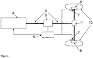
- FIG. 4 shows by way of example the inventive device with a motor 4 and with an engine control unit, which is not shown here.
- the engine is an internal combustion engine in this example.
- the power of the engine 4 is transmitted via an input shaft 9 to an automatic transmission 5 and the transmission outputs the correspondingly requested power via the differential 11 to the wheels 10 on.
- An advantageous control device 6 for the parking is connected to the engine control unit, the brake actuator to the controller 7 and the automatic transmission 5 and can receive and send signals.
- the inventive at least one sensor for determining the distance to a rear object is in FIG. 4 also not shown.
- the at least one sensor likewise supplies information to the control device 6, which is a computer, for example.
- the control device 6 receives a signal from the vehicle driver that the vehicle is to approach an object in an inventive manner.
- the vehicle starts to drive when the reverse gear is engaged and the brake is released, operating the engine 4 at idle speed.
- the control device sends a signal to the transmission control unit 5, so that at least one clutch in the transmission 5 is not fully closed and the vehicle is moving at idle speed at a speed of about 3 km / h. If the at least one sensor detects the object, it sends a corresponding signal and the control device 6 determines the first distance up to which the object is driven at idle speed. Upon reaching the first distance corresponding signals are sent to the brake actuator 7 to initiate the braking operation of at least one braking device 8. At the same time signals are sent to the automatic transmission 5 to open the clutch, so that no power transmission of the motor 4 to the wheels 10 more takes place. The braking is performed such that the stored in the control device 6 holding distance to the object is reached exactly. By the information of the at least one sensor to the control device 6, a calculation of the braking force to achieve the exact holding distance to the object is given advantageous.
Landscapes
- Engineering & Computer Science (AREA)
- Chemical & Material Sciences (AREA)
- Combustion & Propulsion (AREA)
- Transportation (AREA)
- Mechanical Engineering (AREA)
- Automation & Control Theory (AREA)
- Control Of Driving Devices And Active Controlling Of Vehicle (AREA)
- Control Of Vehicle Engines Or Engines For Specific Uses (AREA)
- Regulating Braking Force (AREA)
Description
- Die Erfindung betrifft ein Verfahren zur Steuerung der Annäherung eines Fahrzeuges an ein Objekt gemäß dem Oberbegriff des Anspruchs 1. Die Erfindung betrifft eine Vorrichtung zur Steuerung der Annäherung eines Fahrzeuges an ein Objekt gemäß dem Oberbegriff des Anspruchs 7.
- Bei einem Einparkvorgang eines Fahrzeuges, insbesondere eines automatischen Einparkvorganges bei dem der Fahrer den Einparkvorgang bestimmt und das Fahrzeug die Längs- und Querregelung in die Parklücke übernimmt, ist es wünschenswert, dass besonders Parklücken verwendet werden können, deren Länge für einen Einparkvorgang vom Fahrzeugführer schwer abgeschätzt werden kann. Die Länge der Parklücke wird jedoch auch von dem System des Fahrzeugs zum Einparken bestimmt. Aus diesem Grund wird beim Vermessen und anschließendem Einparken ein relativ großer Abstand an mindestens ein Hindernis gewählt, womit das Einparken in enge Parklücken, bzw. bis kurz vor ein Objekt für die aktuellen Systeme schwer bis gar nicht realisierbar ist.
- Aus dem Stand der Technik ist eine Steuerung der Annäherung an ein Hindernis bei Rückwärtsfahrt bekannt (
DE 196 07 788 B4 ), bei der in einem ersten Abstandsbereich zu einem Hindernis durch Beeinflussung der Motorleistung des Fahrzeugs die Geschwindigkeit des Fahrzeugs unter einen vorgegebenen Grenzwert gehalten wird und in einem zweiten Abstandsbereich die Fahrgeschwindigkeit auf einen zweiten Grenzwert begrenzt wird durch Aufbau von Bremskraft in den Radbremsen. Des Weiteren ist aus derDE 10 2004 059 131 A1 eine Fahrzeugsteuervorrichtung für das Bewegen eines Fahrzeugs um eine kleine Strecke bekannt, die eine Steuereinheit aufweist, die auf Grundlage einer berechneten Antriebskraft eine Antriebsvorrichtung und eine Bremsvorrichtung steuert. Ebenfalls bekannt ist aus derEP 1 327 553 A2 ein Steuerungssystem einer Einparkhilfe, die ein Modul zur Fahrgeschwindigkeitskontrolle basierend auf der Steuerung der Bremskraft aufweist. - Die Aufgabe der Erfindung besteht darin, den vorbekannten Stand der Technik zu optimieren um ein Fahrzeug noch exakter an ein Objekt heranzuführen.
- Die Lösung der Aufgabe wird durch die unabhängigen Patentansprüche 1 und 7 erreicht. Weitere vorteilhafte Ausführungen der Erfindung finden sich in den Unteransprüchen.
- Erfindungsgemäß wird bei einer Annäherung eines Fahrzeugs an ein Objekt das Fahrzeug mit der Leerlaufdrehzahl der Antriebseinrichtung, beispielsweise einem Verbrennungsmotor, betrieben. Objekte können Fahrzeuge oder aber auch andere Hindernisse, wie Pfeiler, Bordsteine, Bäume, usw. sein. Die Verwendung der Leerlaufdrehzahl ist besonders vorteilhaft, da nicht in die Motorsteuerung eingegriffen wird, um das Fahrzeug zu bewegen. Insbesondere für ein Fahrzeug mit Automatikgetriebe ist diese Erfindung besonders vorteilhaft, da bei eingelegtem Gang die Leerlaufdrehzahl das Fahrzeug mit niedriger Geschwindigkeit, ohne weitere Beeinflussung durch den Fahrer, bewegt. Dies erfinderische Annäherung an ein Objekt erfolgt in einem ersten Abstandsbereich zum Objekt, z.B. bei Rückwärtsfahrt an das Objekt. Erfindungsgemäß detektiert ein Sensor, wie z.B. ein Ultraschallsensor am Heckbereich eines Fahrzeugs, den Abstand zum Objekt.
- Die Leerlaufdrehzahl ist für den Fachmann bekannt (s. Kraftfahr Technisches Taschenbuch, Bosch, 22. Auflage) und wird dadurch bestimmt, dass Sensoren die Motordrehzahl, Motortemperatur und Drosselklappenstellung ermitteln. Weiterhin lassen sich auch Belastungszustände von beispielsweise einem Automatikgetriebe, einer Klimaanlage, einer Servolenkung und auch anderen Störgrößen erfassen. Mit diesen Faktoren wird die Leerlaufdrehzahl geregelt. Befindet sich ein Fahrzeug im Leerlaufdrehzahlbetrieb und ein Verbraucher wird hinzugeschaltet, hat dies nahezu keinen Drehzahleinbruch zur Folge und kann mit der Leerlaufdrehzahl abgefangen werden.
- Erfindungsgemäß wird bis zum Erreichen eines ersten Abstandes, der geringer als der zweite Abstand zum Objekt ist und dessen Ende von mindestens einem Sensor und mindestens einer Steuereinrichtung ermittelt wurde, die Übertragung der Motorleistung an die Räder unterbrochen. Dieses Erreichen des ersten Abstandes ab dem die Unterbrechung der Kraftübertragung erfolgt, ist erfindungsgemäß ebenfalls von dem Neigungswinkel des Fahrzeugs und der Bewegungsrichtung des Fahrzeugs zur oder entgegen einer Neigung abhängig. Diese Parameter werden durch bekannte Sensoren, wie z.B. Raddrehzahlsensoren und/ oder Gangposition und/oder Neigungssensoren etc. die dem Fachmann bekannt sind, an die Steuereinrichtung übermittelt. Die Steuereinrichtung ermittelt anhand der Geschwindigkeit des Fahrzeugs im Leerlauf und der genannten Umfeld- sowie Sensorinformationen den Abstand zum Hindernis bei Annäherung, ab dem ein Bremsvorgang eingeleitet und die Kraftübertragung des Motors auf die Räder unterbrochen wird.
- Es ist besonders erfinderisch, dass nach Erreichen des Abstandes bis zu einem zweiten Abstand, der dem Halteabstand entspricht, mit der Bremseinrichtung bis zum Stillstand abgebremst wird. Es ist weiterhin sehr vorteilhaft, dass bei Betätigung der Bremseinrichtung ein Steuersignal erzeugt wird, um mindestens eine Kupplung zur Kraftübertragung der Antriebseinrichtung an mindestens ein Rad mittels eines Aktuators zu öffnen.
- Es ist besonders erfinderisch, dass während des Leerlaufbetriebes des Fahrzeugs die Kupplung, z.B. die Getriebekupplung für den ersten Gang oder die niedrigste Übersetzung, z.B. für den Rückwärtsgang, nicht ganz geschlossen ist. Durch dieses Schleifen der Kupplung wird die Geschwindigkeit des Fahrzeugs zur Annäherung an das Objekt weiter verringert auf ca. 1 km/h bis 5 km/h, vorzugsweise 3 km/h, was für die genaue Annäherung an ein Objekt sehr vorteilhaft ist.
- Es ist im Sinne der Erfindung, dass die Steuereinrichtung mindestens einen Bremsaktuator steuert, um ein aktives Bremsen bis zum Stillstand vor einem Hindernis zu erreichen. Dies hat zum einen den Vorteil, dass der Stillstand an ein Hindernis exakt gesteuert wird, und zum anderen, dass das Fahrzeug bei Stillstand in dieser Position gehalten wird, insbesondere, indem die Funktion der elektrischen Parkbremse bei Erreichen des Stillstandes automatisch aktiviert ist, bzw. wird.
- Es ist vorteilhaft, dass beim Eintreten eines weiteren Objektes, wie z.B. einem Ball in die Annäherungstrajektorie zwischen dem einparkenden Fahrzeug und dem eigentlichen Objekt, ein aktives Bremsen sofort möglich ist, um bereits vor diesem weiteren Objekt zum Stehen zu kommen. Das weitere Objekt wird durch mindestens einen Sensor, wie beispielsweise dem Ultraschallsensor sofort erkannt und an die Recheneinrichtung übermittelt, die unmittelbar den Bremsvorgang aktiviert.
- Der Halteabstand zum Objekt bis zu dem eingeparkt werden soll, ist z.B. abhängig von einer vorher durch das Fahrzeug beim Vorbeifahren vermessenen Parklücke, wenn es sich um eine Längs- oder Querparklücke handelt. Nach der vorbeifahrt bekommt der Fahrzeugführer das Signal, dass ein Einparkvorgang möglich ist. Durch Betätigung eines Bedienelementes wird der Einparkvorgang in die Parklücke gestartet.
- Durch die Bewegung des Fahrzeugs an das Objekt mit Leerlaufdrehzahl bis zu einem ersten Abstand wird eine niedrige Geschwindigkeit erreicht, die für das genaue Heranfahren an das Objekt sehr vorteilhaft ist. Durch die Abkopplung der Antriebseinrichtung und dem beginn des Bremsvorganges wird die Geschwindigkeit bis zum Stillstand weiter reduziert, um einen exakten Halteabstand zum Hindernis zu erreichen. Bei niedriger Geschwindigkeit ist eine exaktere Auswertung der Sensorsignale möglich und ein genaues Bremsen bis zum Stillstand. Die Ansteuerung mindestens einer Bremse des Fahrzeugs, kann beispielsweise über eine elektronische Bremsensteuerung geschehen, wie z.B. dem bekannten ESP-System (Elektronisches Stabilitäts-Programm).
- Der Leerlaufbetrieb bedeutet beispielsweise für ein Fahrzeug mit Automatikgetriebe, dass das Fahrzeug mit einer eingelegten Gangwahlstufe, z.B. "R" für "Rückwärtsfahrt" oder "D" für "Fahren" sich bewegt, ohne dass der Fahrzeugführer die Bremse und/ oder das Gaspedal aktiviert, d.h. keinen Einfluss auf die Längsführung des Fahrzeugs nimmt. Ein Eingriff in die Motorsteuerung ist erfinderisch für den Leerlaufbetrieb nicht notwendig. Der Leerlaufbetrieb wir mit Leerlaufdrehzahl des Motors betrieben, die so gewählt ist, dass der Motor nicht aus geht und das Fahrzeug nach wie vor bewegt wird. Die Leerlaufdrehzahl liegt im Bereich von ca. 800 U/min bis ca. 1500 U/min. Wird das Fahrzeug mit einem Elektromotor für die Annäherung an ein Hindernis betrieben, ist mit Leerlaufdrehzahl der Bereich gemeint bei dem das Fahrzeug mit Automatikgetriebe sich im Geschwindigkeitsbereich von ca. 1km/h bis 10 km/h bewegt, ohne dass der Fahrzeugführer aktiv in die Längsführung eingreift.
- Es ist besonders vorteilhaft, dass bei einem Fahrzeug mit Automatikgetriebe bei erfindungsgemäßer Annäherung an ein Objekt, z.B. in eine Parklücke, die Gangwahl für den Richtungswechsel bei mehrzügigem Einparken über mindestens eine Steuereinrichtung und mindestens einem Aktuator veranlasst wird, so dass ein automatisches Einparken ohne Eingriff des Fahrers möglich ist. Mit anderen Worten erfolgt der Gangwechsel von alleine.
- Bei einem Fahrzeug mit Handschaltgetriebe wird das Fahrzeug bei Leerlaufdrehzahl im ersten Gang vorwärts, bzw. bei Rückwärtsfahrt im Rückwärtsgang bewegt, ohne dass der Fahrzeugführer das Bremspedal und/oder Gaspedal aktiv betätigt. Durch einen Aktuator, der erfinderisch gesteuert wird, wird die Kupplung zur Kraftübertragung bei Erreichen eines zweiten Abstandes zum Hindernis geöffnet. Es ist ebenfalls im Sinne der Erfindung, dass anstelle der Steuerung des Aktuators der Fahrzeugführer eine Information erhält, die optisch und/oder akustisch ist, und ihm signalisiert die Kupplung zu betätigen. Auch hier ermöglicht die Erfindung durch Ausnutzung der Leerlaufdrehzahl einen besonders energiesparenden Einsatz des Fahrzeugs und durch niedrige Geschwindigkeit ein exaktes Heranfahren an das Hindernis bis zum Stillstand. Alternativ kann der Aktuator so ausgestaltet sein, dass ein Schleifen der Kupplung auch hier ermöglicht wird.
- Es ist im Sinne der Erfindung, dass bei Annäherung an ein Objekt an einer Neigung, z.B. auf einer Bergstraße, wenn sich das Fahrzeug also zum Objekt gegen die Neigung bewegen muss, lediglich bei der Anfahrt aus dem Stillstand in die Motorsteuerung eingegriffen wird, um das Fahrzeug kurzzeitig vor dem erfinderischen Leerlaufbetrieb zu beschleunigen.
- Erfinderisch wird das heranfahren an ein Objekt durch Betätigen eines Bedienelementes und/oder einer Sprachbedienung eingeleitet.
- Besonders erfinderisch ist die Vorrichtung zur Steuerung eines Fahrzeugs bis an ein Objekt, wobei eine Antriebseinrichtung das Fahrzeug bewegt, eine Bremseinrichtung das Fahrzeug abbremst, mindestens ein Sensor den Abstand zum Objekt detektiert und mindestens eine Steuereinrichtung die Daten aufnimmt, auswertet und entsprechende Steuersignale ausgibt. Die erfinderische Vorrichtung bringt das Fahrzeug mittels der Antriebseinrichtung auf eine Geschwindigkeit, die maximal der Antriebsgeschwindigkeit mit Leerlaufdrehzahl entspricht. Die Antriebseinrichtung hält die Geschwindigkeit bis zu einem ersten Abstand und die Bremseinrichtung bremst das Fahrzeug bis zu einem zweiten Abstand, der dem Halteabstand entspricht, bis zum Stillstand.
- Es ist weiterhin sehr vorteilhaft, die Erfindung für Hybrid- und / oder Elektrofahrzeuge zu verwenden. Bei Betrieb mit Elektroantrieb ist es vorteilhaft, dass mit dem Elektromotor generatorisch gebremst und die gewonnene Energie rekuperiert, d.h. der Batterie zurückgeführt wird. In dieser vorteilhaften Ausgestaltung der Erfindung würde keine Öffnung der Kupplung erfolgen.
- Bevorzugte Ausführungsformen der Erfindung werden nachfolgend anhand der Zeichnungen erläutert.
- Figur 1 bis 3:
- Beispielhafter Einparkvorgang
- Figur 4:
- Schematischer Aufbau der erfindungsgemäßen Vorrichtung
-
Figur 1 zeigt einen beispielhaften Einparkvorgang gemäß der Erfindung. Beim Vorbeifahren an den Objekten 2 und 3 nimmt das Fahrzeug 1 mittels seitlich gerichteten Ultraschallsensoren die Parklücke zwischen diesen beiden Objekten 2 und 3 auf und signalisiert dem Fahrzeugführer des Fahrzeuges 1, dass ein Einparkvorgang möglich ist. In einer Steuereinrichtung wurde anhand der ermittelten Daten eine Einparktrajektorie berechnet. Nachdem das Fahrzeug 1 steht, betätigt der Fahrzeugführer die Einleitung des Einparkvorganges mit einem Bedienelement. Er wird dann z.B. über eine Anzeigeeinrichtung aufgefordert, den Rückwärtsgang, in diesem Beispielfall die Parkhebelposition "R" für Rückwärtsfahrt mit Automatikgetriebe, einzulegen und die Bremse zu lösen. Mit der Leerlaufdrehzahl des Motors bewegt sich das Fahrzeug bis zu einem ersten Abstand zum Objekt 3 entlang der berechneten Trajektorie. Die Querführung erfolgt automatisch über eine Steuerung der elektromechanischen Lenkung des Fahrzeugs 1. Die hinteren Sensoren die hier ebenfalls nicht dargestellt sind und auch Ultraschallsensoren sein können, des Fahrzeugs 1 ermitteln den Abstand zum Objekt 3. Ab einem im Steuergerät berechneten Abstand zum Hindernis (Erreichen des ersten Abstandes), wird erfinderisch ein Signal an den Aktuator im Automatikgetriebe übermittelt, der daraufhin die Kupplung öffnet und die Momentenübertragung des Motors an die Räder unterbricht. Das Steuergerät sendet mindestens ein Signal an den Bremsaktuator, z.B. der ESP-Bremse mindestens eines Rades und leitet den Bremsvorgang ein. Durch die Informationen der hinteren Sensoren und z.B. einem im Speicher der Steuereinrichtung 6 abgelegten Halteabstand wird die Bremskraft berechnet die notwendig ist, um diesen exakten zweiten Abstand zu erreichen. Diese Berechnung findet im Steuergerät statt, welches die Signale für den Bremsvorgang steuert. - In
Fig. 2 ist die Geschwindigkeit des Fahrzeugs über den Weg für den inFig.1 beispielhaften Einparkvorgang dargestellt. Aus dem Stillstand wird das Fahrzeug kurzzeitig beschleunigt, nachdem der Fahrzeugführer den Rückwärtsgang im Automatikgetriebe eingelegt und die Bremse geöffnet hat. Die Fahrzeuggeschwindigkeit erhöht sich auf die Geschwindigkeit, die die Leerlaufdrehzahl ermöglicht. Im Sinne der Erfindung schleift die Kupplung bei Leerlaufdrehzahl, so dass mit einer niedrigen Geschwindigkeit von beispielsweise 3 km/h gefahren wird. Die Geschwindigkeit wird bis zum Erreichen des ersten Abstandes beibehalten. Bei Erreichen des ersten Abstandes wird die Kupplung geöffnet und die Fahrzeuggeschwindigkeit bis zum erreichen des zweiten Abstandes, der dem Halteabstand entspricht, bis zum Stillstand abgebremst. -
Fig. 3 zeigt beispielhaft den Verlauf der Motorleistung über die Wegstrecke, wenn das Fahrzeug entgegen einer Neigung bewegt werden muss. Die Motorleistung wird kurzzeitig erhöht, um das Anfahren des Fahrzeugs zu verbessern. Die Drehzahl des Motors ist in diesem Fall kurzzeitig höher als die Leerlaufdrehzahl. Nach dem Anfahren wird die Motorleistung zurückgenommen und das Fahrzeug im Leerlauf betrieben. Die Erhöhung ist abhängig vom gemessenen Weg zum Hindernis und von der ermittelten Neigung sowie Fahrzeugeigenschaften, wie beispielsweise dem Gewicht, den Reifen, usw. In der Steuereinrichtung 6 wird berechnet, ab welchem Abstand zum Objekt 3 die Motorleistung zurückgenommen wird um das Fahrzeug dann erfinderisch mit Leerlaufdrehzahl zu bewegen. Anhand der genannten Informationen wird ebenfalls berechnet, ab wann der erste Abstand zu Ende ist, d.h. die Kupplung geöffnet wird. Erfinderisch kann dieser Abstand durch kontinuierliche Informationen an das Steuergerät des mindestens einen hinteren Sensors korrigiert werden. InFigur 3 wird ebenfalls deutlich, dass nach Erreichen des ersten Abstandes, d.h. nach Unterbrechung der Momentenübertragung durch Öffnen der Kupplung, die Leerlaufdrehzahl annähernd konstant bleibt. -
Figur 4 zeigt beispielhaft die erfinderische Vorrichtung mit einem Motor 4 und mit einem Motorsteuergerät, welches hier nicht dargestellt ist. Der Motor ist in diesem Beispiel ein Verbrennungsmotor. Die Leistung des Motors 4 wird über eine Antriebswelle 9 an ein Automatikgetriebe 5 übertragen und das Getriebe gibt die entsprechend angeforderte Leistung über das Differenzial 11 an die Räder 10 weiter. Eine vorteilhafte Steuereinrichtung 6 für den Einparkvorgang, ist mit dem Motorsteuergerät, dem Bremsaktuator mit Steuergerät 7 und dem Automatikgetriebe 5 verbunden und kann Signale empfangen und senden. Der erfindungsgemäße mindestens eine Sensor zur Ermittlung des Abstandes zu einem hinteren Objekt ist inFigur 4 ebenfalls nicht dargestellt. Der mindestens eine Sensor liefert ebenfalls Informationen an die Steuereinrichtung 6, die beispielsweise ein Rechner ist. Die Steuereinrichtung 6 bekommt vom Fahrzeugführer ein Signal, dass sich das Fahrzeug erfinderisch an ein Objekt annähern soll. Das Fahrzeug beginnt loszufahren, wenn der Rückwärtsgang eingelegt und die Bremse gelöst ist, wobei der Motor 4 mit Leerlaufdrehzahl betrieben wird. Die Steuereinrichtung sendet ein Signal an das Getriebe-Steuergerät 5, so dass mindestens eine Kupplung im Getriebe 5 nicht ganz geschlossen wird und das Fahrzeug mit Leerlaufdrehzahl sich mit einer Geschwindigkeit von ca. 3 km/h bewegt. Sofern der mindestens eine Sensor das Objekt erkennt sendet er ein entsprechendes Signal and die Steuereinrichtung 6 ermittelt den ersten Abstand bis zu dem mit Leerlaufdrehzahl an das Objekt gefahren wird. Bei Erreichen des ersten Abstandes werden entsprechende Signale an den Bremsaktuator 7 gesendet, um den Bremsvorgang an mindestens einer Bremseinrichtung 8 einzuleiten. Gleichzeitig werden Signale an das Automatikgetriebe 5 gesendet, um die Kupplung zu öffnen, so dass keine Kraftübertragung des Motors 4 an die Räder 10 mehr statt findet. Die Bremsung erfolgt derart, dass der in der Steuereinrichtung 6 abgelegte Halteabstand zum Objekt exakt erreicht wird. Durch die Informationen des mindestens einen Sensors an die Steuereinrichtung 6 ist eine Berechnung der Bremskraft zum Erreichen des exakten Halteabstandes zum Objekt vorteilhaft gegeben.
Claims (9)
- Verfahren zur Steuerung eines Fahrzeugs (1) mit einer Antriebseinrichtung (4) und einer Bremseinrichtung (8) während eines Einparkvorganges bis an ein Objekt (3), wobei der Abstand zum Objekt erfasst wird, dadurch gekennzeichnet, dass bis zu einem ersten Abstand des Fahrzeugs zum Objekt (3) das Fahrzeug (1) aus dem Stillstand, ohne Eingriff in die Motorsteuerung, auf eine Einparkgeschwindigkeit gebracht wird, die maximal der mit Leerlaufdrehzahl erreichbaren Antriebsgeschwindigkeit entspricht, die Einparkgeschwindigkeit gehalten wird und nach Erreichen des Abstandes bis zu einem zweiten Abstand, der dem Halteabstand entspricht, mit der Bremseinrichtung (8) bis zum Stillstand abgebremst wird.
- Verfahren nach Anspruch 1 dadurch gekennzeichnet, dass das Fahrzeug (1) mit Leerlaufdrehzahl der Antriebseinrichtung (4) bis zum ersten Abstand mit annähernd geschlossener Kupplung zur Kraftübertragung bewegt wird und nach Erreichen des ersten Abstandes bis zu dem zweiten Abstand die Kupplung geöffnet ist.
- Verfahren nach Anspruch 2 dadurch gekennzeichnet, dass die Kupplung annährend geschlossen, bzw. geöffnet wird.
- Verfahren nach Anspruch 1 dadurch gekennzeichnet, dass die Leerlaufdrehzahl des mindestens einen Motors im Bereich von 600 bis 1500 U/min, vorzugsweise bei ca. 800 U/min liegt.
- Verfahren nach Anspruch 1 dadurch gekennzeichnet, dass als Antriebseinrichtung (4) ein Elektromotor verwendet wird.
- Verfahren nach Anspruch 1 dadurch gekennzeichnet, dass bei Betätigung der Bremseinrichtung (8) die Kupplung geöffnet wird.
- Vorrichtung zur Steuerung eines Fahrzeugs (1) während eines Einparkvorganges bis an ein Objekt (3) mit einer Antriebseinrichtung (4), einer Bremseinrichtung (8), mindestens einem Sensor zur Bestimmung eines Abstandes zu einem Objekt (3) und mindestens einer Steuereinrichtung (6) dadurch gekennzeichnet, dass die Vorrichtung derart ausgebildet ist, dass die Antriebseinrichtung (4) das Fahrzeug (1) aus dem Stillstand, ohne Eingriff in die Motorsteuerung, auf eine Geschwindigkeit bringt, die maximal der Antriebsgeschwindigkeit mit Leerlaufdrehzahl entspricht, die Antriebseinrichtung (4) die Geschwindigkeit bis zu einem ersten Abstand hält und die Bremseinrichtung das Fahrzeug (1) bis zu einem zweiten Abstand zum Objekt (3), der dem Halteabstand entspricht, bis zum Stillstand bremst.
- Vorrichtung nach Anspruch 7 dadurch gekennzeichnet, dass die Vorrichtung derart ausgebildet ist, dass sie die Antriebsgeschwindigkeit mit Leerlaufdrehzahl mit annährend geschlossener Kupplung hält.
- Vorrichtung nach Anspruch 7 dadurch gekennzeichnet, dass die Antriebseinrichtung (4) ein Elektromotor ist.
Applications Claiming Priority (2)
| Application Number | Priority Date | Filing Date | Title |
|---|---|---|---|
| DE102009058139A DE102009058139A1 (de) | 2009-12-12 | 2009-12-12 | Verfahren und Vorrichtung zur Steuerung eines Fahrzeugs an ein Objekt |
| PCT/EP2010/006873 WO2011069589A1 (de) | 2009-12-12 | 2010-11-11 | Verfahren und vorrichtung zur steuerung eines fahrzeugs an ein objekt während eines einparkvorgangs |
Publications (2)
| Publication Number | Publication Date |
|---|---|
| EP2509839A1 EP2509839A1 (de) | 2012-10-17 |
| EP2509839B1 true EP2509839B1 (de) | 2019-04-03 |
Family
ID=43305326
Family Applications (1)
| Application Number | Title | Priority Date | Filing Date |
|---|---|---|---|
| EP10779475.2A Active EP2509839B1 (de) | 2009-12-12 | 2010-11-11 | Verfahren und vorrichtung zur steuerung eines fahrzeugs an ein objekt während eines einparkvorgangs |
Country Status (5)
| Country | Link |
|---|---|
| US (1) | US9327705B2 (de) |
| EP (1) | EP2509839B1 (de) |
| CN (1) | CN102652091B (de) |
| DE (1) | DE102009058139A1 (de) |
| WO (1) | WO2011069589A1 (de) |
Families Citing this family (18)
| Publication number | Priority date | Publication date | Assignee | Title |
|---|---|---|---|---|
| DE102011083269B4 (de) * | 2011-09-23 | 2024-05-08 | Bayerische Motoren Werke Aktiengesellschaft | Verfahren zur Steuerung eines Antriebssystems in einem Kraftfahrzeug |
| DE102014208917B4 (de) * | 2013-07-02 | 2021-07-01 | Ford Global Technologies, Llc | Steuerung der Fahrzeuggeschwindigkeit während des Einparkens |
| DE102014221835A1 (de) | 2014-10-27 | 2016-04-28 | Ford Global Technologies, Llc | Verfahren und Vorrichtung zur Fahrzeugsteuerung |
| DE102015116542A1 (de) * | 2015-09-30 | 2017-03-30 | Valeo Schalter Und Sensoren Gmbh | Verfahren zum Bestimmen einer Parkfläche zum Parken eines Kraftfahrzeugs, Fahrerassistenzsystem sowie Kraftfahrzeug |
| WO2017100716A1 (en) | 2015-12-11 | 2017-06-15 | Eaton Corporation | Autonomous dock |
| CN106004755A (zh) * | 2016-08-02 | 2016-10-12 | 东南(福建)汽车工业有限公司 | 基于车身稳定系统esc的泊车防刮碰控制系统 |
| CN106781693A (zh) * | 2016-12-26 | 2017-05-31 | 上海蔚来汽车有限公司 | 倒车控制方法 |
| DE102018200767A1 (de) * | 2017-02-13 | 2018-08-16 | Ford Global Technologies, Llc | Verfahren zur Steuerung des Einparkvorgangs eines Hybrid-Elektrofahrzeugs |
| KR102215428B1 (ko) * | 2017-08-10 | 2021-02-17 | 닛산 지도우샤 가부시키가이샤 | 주차 제어 방법 및 주차 제어 장치 |
| DE102017216457A1 (de) * | 2017-09-18 | 2019-03-21 | Robert Bosch Gmbh | Verfahren zur Bestimmung einer maximalen Geschwindigkeit eines Fahrzeugs während eines Einparkmanövers |
| FR3078307A1 (fr) * | 2018-02-23 | 2019-08-30 | Psa Automobiles Sa | Procede de surveillance d’une trajectoire de roulage en marche rampante pour un vehicule automobile |
| US10829099B2 (en) | 2018-05-14 | 2020-11-10 | Ford Global Technologies, Llc | Auto-calibrated brake control for vehicles at low speeds |
| CN109353335B (zh) * | 2018-11-21 | 2020-07-17 | 清华大学苏州汽车研究院(吴江) | 一种泊车车位检测方法及装置 |
| CN111516676B (zh) * | 2020-04-30 | 2022-06-07 | 重庆长安汽车股份有限公司 | 一种自动泊车方法、系统、汽车及计算机可读存储介质 |
| DE102020125259A1 (de) | 2020-09-28 | 2022-03-31 | Bayerische Motoren Werke Aktiengesellschaft | Verfahren zum Unterstützen eines Fahrers beim Rangieren eines zumindest teilweise elektrisch angetriebenen Fahrzeugs, Fahrerassistenzsystem sowie Fahrzeug |
| CN114954649B (zh) * | 2021-02-24 | 2023-08-15 | 广州汽车集团股份有限公司 | 一种泊车方法、电子设备和计算机可读存储介质 |
| DE102021204622B4 (de) | 2021-05-06 | 2024-07-18 | Zf Friedrichshafen Ag | Fahrzeugvorrichtung und Verfahren zum Bestimmen einer Kupplungsöffnungsposition und einer Bremsposition |
| CN113771828A (zh) * | 2021-09-29 | 2021-12-10 | 采埃孚商用车系统(青岛)有限公司 | 一种自动驾驶定点停车的控制方法及系统 |
Family Cites Families (17)
| Publication number | Priority date | Publication date | Assignee | Title |
|---|---|---|---|---|
| DE4142580A1 (de) | 1991-12-21 | 1993-06-24 | Bosch Gmbh Robert | Verfahren und vorrichtung zum betrieb einer elektromotorischen servolenkung |
| DE19607788B4 (de) | 1996-03-01 | 2009-05-07 | Robert Bosch Gmbh | Verfahren und Vorrichtung zur Steuerung der Annäherung eines Fahrzeugs an ein Hindernis |
| DE19745127A1 (de) * | 1997-10-13 | 1999-04-15 | Daimler Chrysler Ag | Vorrichtung und Verfahren zum Verhindern von Kollisionen eines Fahrzeugs mit einem Hindernis beim Einparken des Fahrzeugs |
| US6071211A (en) * | 1998-11-18 | 2000-06-06 | Eaton Corporation | Idle drive torque control for automated vehicle master clutch |
| DE19900314C2 (de) | 1999-01-07 | 2000-10-19 | Daimler Chrysler Ag | Verfahren und Vorrichtung zur Abbremsung eines Kraftfahrzeugs im Nahbereich mit einem Hindernis |
| US7068211B2 (en) * | 2000-02-08 | 2006-06-27 | Cambridge Consultants Limited | Methods and apparatus for obtaining positional information |
| DE10063062A1 (de) | 2000-12-18 | 2002-06-20 | Lucas Varity Gmbh | Verfahren und Vorrichtung zum Steuern einer Bremsausrüstung eines Kraftfahrzeuges |
| DE10105749B4 (de) * | 2001-02-08 | 2010-12-30 | Man Nutzfahrzeuge Ag | Verfahren für ein erleichtertes Rangieren in einem Nutzfahrzeug |
| US6634984B1 (en) * | 2001-02-08 | 2003-10-21 | Ford Global Technologies, Llc | Method of controlling engine idle speed during launch from neutral idle operation |
| JP3755464B2 (ja) * | 2002-01-11 | 2006-03-15 | トヨタ自動車株式会社 | 駐車支援装置 |
| DE10220837A1 (de) * | 2002-05-08 | 2003-11-27 | Daimler Chrysler Ag | Vorrichtung zur Parklückensuche mittels Radar |
| JP4079083B2 (ja) | 2003-12-12 | 2008-04-23 | トヨタ自動車株式会社 | 車両の制御装置 |
| JP4618035B2 (ja) * | 2005-07-27 | 2011-01-26 | 株式会社アドヴィックス | 車両走行制御装置 |
| DE102005061909A1 (de) * | 2005-12-23 | 2007-07-05 | Volkswagen Ag | Parklenkassistenzsystem und Verfahren zum Betreiben eines Parklenkassistenzsystems |
| DE102006045418A1 (de) * | 2006-09-26 | 2008-04-10 | GM Global Technology Operations, Inc., Detroit | Kraftfahrzeug mit einem Parkassistenzsystem |
| US7719410B2 (en) * | 2007-01-08 | 2010-05-18 | Gm Global Technology Operations, Inc. | Threat assessment state processing for collision warning, mitigation and/or avoidance in ground-based vehicles |
| JP5182545B2 (ja) * | 2007-05-16 | 2013-04-17 | アイシン精機株式会社 | 駐車支援装置 |
-
2009
- 2009-12-12 DE DE102009058139A patent/DE102009058139A1/de not_active Withdrawn
-
2010
- 2010-11-11 WO PCT/EP2010/006873 patent/WO2011069589A1/de active Application Filing
- 2010-11-11 CN CN201080055675.6A patent/CN102652091B/zh active Active
- 2010-11-11 EP EP10779475.2A patent/EP2509839B1/de active Active
- 2010-11-11 US US13/515,465 patent/US9327705B2/en active Active
Non-Patent Citations (1)
| Title |
|---|
| None * |
Also Published As
| Publication number | Publication date |
|---|---|
| CN102652091B (zh) | 2017-09-08 |
| US20120310459A1 (en) | 2012-12-06 |
| EP2509839A1 (de) | 2012-10-17 |
| US9327705B2 (en) | 2016-05-03 |
| WO2011069589A1 (de) | 2011-06-16 |
| CN102652091A (zh) | 2012-08-29 |
| DE102009058139A1 (de) | 2011-06-16 |
Similar Documents
| Publication | Publication Date | Title |
|---|---|---|
| EP2509839B1 (de) | Verfahren und vorrichtung zur steuerung eines fahrzeugs an ein objekt während eines einparkvorgangs | |
| DE102010060079B4 (de) | Verfahren und Steuerungssystem zum Öffnen des Antriebsstrangs eines Kraftfahrzeuges | |
| DE102010030486B4 (de) | Verfahren zum halbautomatischen Einparken eines Kraftfahrzeuges sowie ein Einparksystem | |
| DE102004059131B4 (de) | Steuervorrichtung für ein Fahrzeug | |
| DE102012213815A1 (de) | Verfahren und System zum Anhalten eines Kraftfahrzeugs | |
| DE102011083332B4 (de) | Verfahren und Vorrichtung zum automatischen Aktivieren bzw. Deaktivieren einer Segel-Betriebsart bei einem Kraftfahrzeug mit Verbrennungsmotor | |
| DE102004017635A1 (de) | Rollsperre | |
| DE102013216630A1 (de) | Verfahren und Vorrichtung zur Steuerung eines assistierten Parkvorgangs eines Kraftfahrzeugs | |
| DE10221835A1 (de) | Verfahren zur Regelung eines Anfahrelements | |
| EP2580494B1 (de) | Verfahren zur einstellung von schaltpunkten in einem getriebe oder zur erhöhung des drehmoments einer elektrischen antriebsmaschine | |
| EP2766233A1 (de) | Steuerungseinrichtung eines kraftfahrzeugs und verfahren zum betreiben desselben | |
| EP3328695A1 (de) | Verfahren zum abbremsen eines fahrzeugs | |
| EP1609658B1 (de) | Verfahren und Vorrichtung zum automatischen Anfahren | |
| DE102008036048A1 (de) | Verfahren zur Ansteuerung von Fahrzeugkomponenten zum automatischen Freischaukeln eines Kraftfahrzeugs | |
| EP2358575B1 (de) | Verfahren zum betreiben eines antriebsstrangs | |
| EP2159121A1 (de) | Steuereinrichtung und Verfahren zur Durchführung eines automatischen Einparkvorgangs | |
| DE102007027357A1 (de) | Verfahren und Einrichtung zum Rangieren eines Kraftfahrzeugs | |
| DE102010026769A1 (de) | Verfahren und Vorrichtung zum Betrieb eines Fahrzeugs | |
| DE102006056627B4 (de) | Verfahren und Vorrichtung zur Sicherstellung des Stillstandes eines Kraftfahrzeuges | |
| EP2709890B1 (de) | Verfahren für ein fahrzeug mit einer elektrischen maschine | |
| DE102018114602A1 (de) | Fahrzeuge, systeme und verfahren zum schalten von schaltgetrieben in den leerlauf während des autonomen bremsens | |
| WO2014170001A1 (de) | Verfahren zum automatischen anfahren eines kraftfahrzeugs mit einem von hand zu schaltenden getriebe | |
| DE102005027615B4 (de) | Verfahren und Vorrichtung zum Steuern eines eine Brennkraftmaschine und ein stufenloses Getriebe enthaltenden Fahrzeugantriebsstrangs | |
| DE102015212928B4 (de) | Verfahren zum Betreiben eines Antriebssystems eines Kraftfahrzeugs, Antriebssystem für ein Kraftfahrzeug und Kraftfahrzeug | |
| DE102012019036A1 (de) | Verfahren zur Regelung eines elektromechanischen Kupplungssystems in einem Kraftfahrzeug |
Legal Events
| Date | Code | Title | Description |
|---|---|---|---|
| PUAI | Public reference made under article 153(3) epc to a published international application that has entered the european phase |
Free format text: ORIGINAL CODE: 0009012 |
|
| 17P | Request for examination filed |
Effective date: 20120712 |
|
| AK | Designated contracting states |
Kind code of ref document: A1 Designated state(s): AL AT BE BG CH CY CZ DE DK EE ES FI FR GB GR HR HU IE IS IT LI LT LU LV MC MK MT NL NO PL PT RO RS SE SI SK SM TR |
|
| DAX | Request for extension of the european patent (deleted) | ||
| STAA | Information on the status of an ep patent application or granted ep patent |
Free format text: STATUS: EXAMINATION IS IN PROGRESS |
|
| 17Q | First examination report despatched |
Effective date: 20170511 |
|
| GRAP | Despatch of communication of intention to grant a patent |
Free format text: ORIGINAL CODE: EPIDOSNIGR1 |
|
| STAA | Information on the status of an ep patent application or granted ep patent |
Free format text: STATUS: GRANT OF PATENT IS INTENDED |
|
| INTG | Intention to grant announced |
Effective date: 20181011 |
|
| GRAJ | Information related to disapproval of communication of intention to grant by the applicant or resumption of examination proceedings by the epo deleted |
Free format text: ORIGINAL CODE: EPIDOSDIGR1 |
|
| STAA | Information on the status of an ep patent application or granted ep patent |
Free format text: STATUS: EXAMINATION IS IN PROGRESS |
|
| GRAP | Despatch of communication of intention to grant a patent |
Free format text: ORIGINAL CODE: EPIDOSNIGR1 |
|
| STAA | Information on the status of an ep patent application or granted ep patent |
Free format text: STATUS: GRANT OF PATENT IS INTENDED |
|
| INTC | Intention to grant announced (deleted) | ||
| GRAS | Grant fee paid |
Free format text: ORIGINAL CODE: EPIDOSNIGR3 |
|
| GRAA | (expected) grant |
Free format text: ORIGINAL CODE: 0009210 |
|
| STAA | Information on the status of an ep patent application or granted ep patent |
Free format text: STATUS: THE PATENT HAS BEEN GRANTED |
|
| INTG | Intention to grant announced |
Effective date: 20190213 |
|
| AK | Designated contracting states |
Kind code of ref document: B1 Designated state(s): AL AT BE BG CH CY CZ DE DK EE ES FI FR GB GR HR HU IE IS IT LI LT LU LV MC MK MT NL NO PL PT RO RS SE SI SK SM TR |
|
| REG | Reference to a national code |
Ref country code: GB Ref legal event code: FG4D Free format text: NOT ENGLISH |
|
| REG | Reference to a national code |
Ref country code: CH Ref legal event code: EP Ref country code: AT Ref legal event code: REF Ref document number: 1115363 Country of ref document: AT Kind code of ref document: T Effective date: 20190415 |
|
| REG | Reference to a national code |
Ref country code: DE Ref legal event code: R096 Ref document number: 502010015912 Country of ref document: DE |
|
| REG | Reference to a national code |
Ref country code: IE Ref legal event code: FG4D Free format text: LANGUAGE OF EP DOCUMENT: GERMAN |
|
| REG | Reference to a national code |
Ref country code: NL Ref legal event code: MP Effective date: 20190403 |
|
| REG | Reference to a national code |
Ref country code: LT Ref legal event code: MG4D |
|
| PG25 | Lapsed in a contracting state [announced via postgrant information from national office to epo] |
Ref country code: NL Free format text: LAPSE BECAUSE OF FAILURE TO SUBMIT A TRANSLATION OF THE DESCRIPTION OR TO PAY THE FEE WITHIN THE PRESCRIBED TIME-LIMIT Effective date: 20190403 |
|
| PG25 | Lapsed in a contracting state [announced via postgrant information from national office to epo] |
Ref country code: HR Free format text: LAPSE BECAUSE OF FAILURE TO SUBMIT A TRANSLATION OF THE DESCRIPTION OR TO PAY THE FEE WITHIN THE PRESCRIBED TIME-LIMIT Effective date: 20190403 Ref country code: LT Free format text: LAPSE BECAUSE OF FAILURE TO SUBMIT A TRANSLATION OF THE DESCRIPTION OR TO PAY THE FEE WITHIN THE PRESCRIBED TIME-LIMIT Effective date: 20190403 Ref country code: CZ Free format text: LAPSE BECAUSE OF FAILURE TO SUBMIT A TRANSLATION OF THE DESCRIPTION OR TO PAY THE FEE WITHIN THE PRESCRIBED TIME-LIMIT Effective date: 20190403 Ref country code: ES Free format text: LAPSE BECAUSE OF FAILURE TO SUBMIT A TRANSLATION OF THE DESCRIPTION OR TO PAY THE FEE WITHIN THE PRESCRIBED TIME-LIMIT Effective date: 20190403 Ref country code: FI Free format text: LAPSE BECAUSE OF FAILURE TO SUBMIT A TRANSLATION OF THE DESCRIPTION OR TO PAY THE FEE WITHIN THE PRESCRIBED TIME-LIMIT Effective date: 20190403 Ref country code: PT Free format text: LAPSE BECAUSE OF FAILURE TO SUBMIT A TRANSLATION OF THE DESCRIPTION OR TO PAY THE FEE WITHIN THE PRESCRIBED TIME-LIMIT Effective date: 20190803 Ref country code: AL Free format text: LAPSE BECAUSE OF FAILURE TO SUBMIT A TRANSLATION OF THE DESCRIPTION OR TO PAY THE FEE WITHIN THE PRESCRIBED TIME-LIMIT Effective date: 20190403 Ref country code: SE Free format text: LAPSE BECAUSE OF FAILURE TO SUBMIT A TRANSLATION OF THE DESCRIPTION OR TO PAY THE FEE WITHIN THE PRESCRIBED TIME-LIMIT Effective date: 20190403 Ref country code: NO Free format text: LAPSE BECAUSE OF FAILURE TO SUBMIT A TRANSLATION OF THE DESCRIPTION OR TO PAY THE FEE WITHIN THE PRESCRIBED TIME-LIMIT Effective date: 20190703 |
|
| PG25 | Lapsed in a contracting state [announced via postgrant information from national office to epo] |
Ref country code: GR Free format text: LAPSE BECAUSE OF FAILURE TO SUBMIT A TRANSLATION OF THE DESCRIPTION OR TO PAY THE FEE WITHIN THE PRESCRIBED TIME-LIMIT Effective date: 20190704 Ref country code: PL Free format text: LAPSE BECAUSE OF FAILURE TO SUBMIT A TRANSLATION OF THE DESCRIPTION OR TO PAY THE FEE WITHIN THE PRESCRIBED TIME-LIMIT Effective date: 20190403 Ref country code: LV Free format text: LAPSE BECAUSE OF FAILURE TO SUBMIT A TRANSLATION OF THE DESCRIPTION OR TO PAY THE FEE WITHIN THE PRESCRIBED TIME-LIMIT Effective date: 20190403 Ref country code: BG Free format text: LAPSE BECAUSE OF FAILURE TO SUBMIT A TRANSLATION OF THE DESCRIPTION OR TO PAY THE FEE WITHIN THE PRESCRIBED TIME-LIMIT Effective date: 20190703 Ref country code: RS Free format text: LAPSE BECAUSE OF FAILURE TO SUBMIT A TRANSLATION OF THE DESCRIPTION OR TO PAY THE FEE WITHIN THE PRESCRIBED TIME-LIMIT Effective date: 20190403 |
|
| PG25 | Lapsed in a contracting state [announced via postgrant information from national office to epo] |
Ref country code: IS Free format text: LAPSE BECAUSE OF FAILURE TO SUBMIT A TRANSLATION OF THE DESCRIPTION OR TO PAY THE FEE WITHIN THE PRESCRIBED TIME-LIMIT Effective date: 20190803 |
|
| REG | Reference to a national code |
Ref country code: DE Ref legal event code: R097 Ref document number: 502010015912 Country of ref document: DE |
|
| PG25 | Lapsed in a contracting state [announced via postgrant information from national office to epo] |
Ref country code: EE Free format text: LAPSE BECAUSE OF FAILURE TO SUBMIT A TRANSLATION OF THE DESCRIPTION OR TO PAY THE FEE WITHIN THE PRESCRIBED TIME-LIMIT Effective date: 20190403 Ref country code: RO Free format text: LAPSE BECAUSE OF FAILURE TO SUBMIT A TRANSLATION OF THE DESCRIPTION OR TO PAY THE FEE WITHIN THE PRESCRIBED TIME-LIMIT Effective date: 20190403 Ref country code: SK Free format text: LAPSE BECAUSE OF FAILURE TO SUBMIT A TRANSLATION OF THE DESCRIPTION OR TO PAY THE FEE WITHIN THE PRESCRIBED TIME-LIMIT Effective date: 20190403 Ref country code: DK Free format text: LAPSE BECAUSE OF FAILURE TO SUBMIT A TRANSLATION OF THE DESCRIPTION OR TO PAY THE FEE WITHIN THE PRESCRIBED TIME-LIMIT Effective date: 20190403 |
|
| PLBE | No opposition filed within time limit |
Free format text: ORIGINAL CODE: 0009261 |
|
| STAA | Information on the status of an ep patent application or granted ep patent |
Free format text: STATUS: NO OPPOSITION FILED WITHIN TIME LIMIT |
|
| PG25 | Lapsed in a contracting state [announced via postgrant information from national office to epo] |
Ref country code: SM Free format text: LAPSE BECAUSE OF FAILURE TO SUBMIT A TRANSLATION OF THE DESCRIPTION OR TO PAY THE FEE WITHIN THE PRESCRIBED TIME-LIMIT Effective date: 20190403 |
|
| 26N | No opposition filed |
Effective date: 20200106 |
|
| PG25 | Lapsed in a contracting state [announced via postgrant information from national office to epo] |
Ref country code: TR Free format text: LAPSE BECAUSE OF FAILURE TO SUBMIT A TRANSLATION OF THE DESCRIPTION OR TO PAY THE FEE WITHIN THE PRESCRIBED TIME-LIMIT Effective date: 20190403 |
|
| PG25 | Lapsed in a contracting state [announced via postgrant information from national office to epo] |
Ref country code: SI Free format text: LAPSE BECAUSE OF FAILURE TO SUBMIT A TRANSLATION OF THE DESCRIPTION OR TO PAY THE FEE WITHIN THE PRESCRIBED TIME-LIMIT Effective date: 20190403 |
|
| REG | Reference to a national code |
Ref country code: CH Ref legal event code: PL |
|
| PG25 | Lapsed in a contracting state [announced via postgrant information from national office to epo] |
Ref country code: MC Free format text: LAPSE BECAUSE OF FAILURE TO SUBMIT A TRANSLATION OF THE DESCRIPTION OR TO PAY THE FEE WITHIN THE PRESCRIBED TIME-LIMIT Effective date: 20190403 Ref country code: LU Free format text: LAPSE BECAUSE OF NON-PAYMENT OF DUE FEES Effective date: 20191111 Ref country code: CH Free format text: LAPSE BECAUSE OF NON-PAYMENT OF DUE FEES Effective date: 20191130 Ref country code: LI Free format text: LAPSE BECAUSE OF NON-PAYMENT OF DUE FEES Effective date: 20191130 |
|
| REG | Reference to a national code |
Ref country code: BE Ref legal event code: MM Effective date: 20191130 |
|
| PG25 | Lapsed in a contracting state [announced via postgrant information from national office to epo] |
Ref country code: IE Free format text: LAPSE BECAUSE OF NON-PAYMENT OF DUE FEES Effective date: 20191111 |
|
| PG25 | Lapsed in a contracting state [announced via postgrant information from national office to epo] |
Ref country code: BE Free format text: LAPSE BECAUSE OF NON-PAYMENT OF DUE FEES Effective date: 20191130 |
|
| REG | Reference to a national code |
Ref country code: AT Ref legal event code: MM01 Ref document number: 1115363 Country of ref document: AT Kind code of ref document: T Effective date: 20191111 |
|
| PG25 | Lapsed in a contracting state [announced via postgrant information from national office to epo] |
Ref country code: AT Free format text: LAPSE BECAUSE OF NON-PAYMENT OF DUE FEES Effective date: 20191111 |
|
| PG25 | Lapsed in a contracting state [announced via postgrant information from national office to epo] |
Ref country code: CY Free format text: LAPSE BECAUSE OF FAILURE TO SUBMIT A TRANSLATION OF THE DESCRIPTION OR TO PAY THE FEE WITHIN THE PRESCRIBED TIME-LIMIT Effective date: 20190403 |
|
| PG25 | Lapsed in a contracting state [announced via postgrant information from national office to epo] |
Ref country code: HU Free format text: LAPSE BECAUSE OF FAILURE TO SUBMIT A TRANSLATION OF THE DESCRIPTION OR TO PAY THE FEE WITHIN THE PRESCRIBED TIME-LIMIT; INVALID AB INITIO Effective date: 20101111 Ref country code: MT Free format text: LAPSE BECAUSE OF FAILURE TO SUBMIT A TRANSLATION OF THE DESCRIPTION OR TO PAY THE FEE WITHIN THE PRESCRIBED TIME-LIMIT Effective date: 20190403 |
|
| PG25 | Lapsed in a contracting state [announced via postgrant information from national office to epo] |
Ref country code: MK Free format text: LAPSE BECAUSE OF FAILURE TO SUBMIT A TRANSLATION OF THE DESCRIPTION OR TO PAY THE FEE WITHIN THE PRESCRIBED TIME-LIMIT Effective date: 20190403 |
|
| P01 | Opt-out of the competence of the unified patent court (upc) registered |
Effective date: 20230523 |
|
| PGFP | Annual fee paid to national office [announced via postgrant information from national office to epo] |
Ref country code: GB Payment date: 20231121 Year of fee payment: 14 |
|
| PGFP | Annual fee paid to national office [announced via postgrant information from national office to epo] |
Ref country code: IT Payment date: 20231124 Year of fee payment: 14 Ref country code: FR Payment date: 20231123 Year of fee payment: 14 Ref country code: DE Payment date: 20231130 Year of fee payment: 14 |