EP2508777A1 - Système de propulsion pour une éolienne - Google Patents
Système de propulsion pour une éolienne Download PDFInfo
- Publication number
- EP2508777A1 EP2508777A1 EP11174846A EP11174846A EP2508777A1 EP 2508777 A1 EP2508777 A1 EP 2508777A1 EP 11174846 A EP11174846 A EP 11174846A EP 11174846 A EP11174846 A EP 11174846A EP 2508777 A1 EP2508777 A1 EP 2508777A1
- Authority
- EP
- European Patent Office
- Prior art keywords
- shaft
- drive system
- gear
- unit
- hollow
- Prior art date
- Legal status (The legal status is an assumption and is not a legal conclusion. Google has not performed a legal analysis and makes no representation as to the accuracy of the status listed.)
- Granted
Links
- 230000005540 biological transmission Effects 0.000 claims description 46
- 230000008878 coupling Effects 0.000 claims description 31
- 238000010168 coupling process Methods 0.000 claims description 31
- 238000005859 coupling reaction Methods 0.000 claims description 31
- 239000000725 suspension Substances 0.000 claims description 20
- 238000009434 installation Methods 0.000 claims description 4
- 238000004804 winding Methods 0.000 description 3
- 238000012423 maintenance Methods 0.000 description 2
- 239000000463 material Substances 0.000 description 2
- 230000006978 adaptation Effects 0.000 description 1
- 238000010276 construction Methods 0.000 description 1
- 238000013016 damping Methods 0.000 description 1
- 230000001419 dependent effect Effects 0.000 description 1
- 238000011161 development Methods 0.000 description 1
- 230000018109 developmental process Effects 0.000 description 1
- 238000006073 displacement reaction Methods 0.000 description 1
- 229920001971 elastomer Polymers 0.000 description 1
- 239000000806 elastomer Substances 0.000 description 1
- 210000003746 feather Anatomy 0.000 description 1
Images


Classifications
-
- F—MECHANICAL ENGINEERING; LIGHTING; HEATING; WEAPONS; BLASTING
- F03—MACHINES OR ENGINES FOR LIQUIDS; WIND, SPRING, OR WEIGHT MOTORS; PRODUCING MECHANICAL POWER OR A REACTIVE PROPULSIVE THRUST, NOT OTHERWISE PROVIDED FOR
- F03D—WIND MOTORS
- F03D15/00—Transmission of mechanical power
-
- F—MECHANICAL ENGINEERING; LIGHTING; HEATING; WEAPONS; BLASTING
- F03—MACHINES OR ENGINES FOR LIQUIDS; WIND, SPRING, OR WEIGHT MOTORS; PRODUCING MECHANICAL POWER OR A REACTIVE PROPULSIVE THRUST, NOT OTHERWISE PROVIDED FOR
- F03D—WIND MOTORS
- F03D15/00—Transmission of mechanical power
- F03D15/10—Transmission of mechanical power using gearing not limited to rotary motion, e.g. with oscillating or reciprocating members
-
- F—MECHANICAL ENGINEERING; LIGHTING; HEATING; WEAPONS; BLASTING
- F03—MACHINES OR ENGINES FOR LIQUIDS; WIND, SPRING, OR WEIGHT MOTORS; PRODUCING MECHANICAL POWER OR A REACTIVE PROPULSIVE THRUST, NOT OTHERWISE PROVIDED FOR
- F03D—WIND MOTORS
- F03D80/00—Details, components or accessories not provided for in groups F03D1/00 - F03D17/00
- F03D80/70—Bearing or lubricating arrangements
-
- F—MECHANICAL ENGINEERING; LIGHTING; HEATING; WEAPONS; BLASTING
- F16—ENGINEERING ELEMENTS AND UNITS; GENERAL MEASURES FOR PRODUCING AND MAINTAINING EFFECTIVE FUNCTIONING OF MACHINES OR INSTALLATIONS; THERMAL INSULATION IN GENERAL
- F16H—GEARING
- F16H1/00—Toothed gearings for conveying rotary motion
- F16H1/28—Toothed gearings for conveying rotary motion with gears having orbital motion
-
- F—MECHANICAL ENGINEERING; LIGHTING; HEATING; WEAPONS; BLASTING
- F16—ENGINEERING ELEMENTS AND UNITS; GENERAL MEASURES FOR PRODUCING AND MAINTAINING EFFECTIVE FUNCTIONING OF MACHINES OR INSTALLATIONS; THERMAL INSULATION IN GENERAL
- F16H—GEARING
- F16H57/00—General details of gearing
- F16H57/02—Gearboxes; Mounting gearing therein
- F16H57/025—Support of gearboxes, e.g. torque arms, or attachment to other devices
-
- F—MECHANICAL ENGINEERING; LIGHTING; HEATING; WEAPONS; BLASTING
- F16—ENGINEERING ELEMENTS AND UNITS; GENERAL MEASURES FOR PRODUCING AND MAINTAINING EFFECTIVE FUNCTIONING OF MACHINES OR INSTALLATIONS; THERMAL INSULATION IN GENERAL
- F16H—GEARING
- F16H57/00—General details of gearing
- F16H57/02—Gearboxes; Mounting gearing therein
- F16H57/028—Gearboxes; Mounting gearing therein characterised by means for reducing vibration or noise
-
- F—MECHANICAL ENGINEERING; LIGHTING; HEATING; WEAPONS; BLASTING
- F16—ENGINEERING ELEMENTS AND UNITS; GENERAL MEASURES FOR PRODUCING AND MAINTAINING EFFECTIVE FUNCTIONING OF MACHINES OR INSTALLATIONS; THERMAL INSULATION IN GENERAL
- F16H—GEARING
- F16H57/00—General details of gearing
- F16H57/08—General details of gearing of gearings with members having orbital motion
-
- F—MECHANICAL ENGINEERING; LIGHTING; HEATING; WEAPONS; BLASTING
- F05—INDEXING SCHEMES RELATING TO ENGINES OR PUMPS IN VARIOUS SUBCLASSES OF CLASSES F01-F04
- F05B—INDEXING SCHEME RELATING TO WIND, SPRING, WEIGHT, INERTIA OR LIKE MOTORS, TO MACHINES OR ENGINES FOR LIQUIDS COVERED BY SUBCLASSES F03B, F03D AND F03G
- F05B2260/00—Function
- F05B2260/30—Retaining components in desired mutual position
- F05B2260/301—Retaining bolts or nuts
-
- F—MECHANICAL ENGINEERING; LIGHTING; HEATING; WEAPONS; BLASTING
- F05—INDEXING SCHEMES RELATING TO ENGINES OR PUMPS IN VARIOUS SUBCLASSES OF CLASSES F01-F04
- F05B—INDEXING SCHEME RELATING TO WIND, SPRING, WEIGHT, INERTIA OR LIKE MOTORS, TO MACHINES OR ENGINES FOR LIQUIDS COVERED BY SUBCLASSES F03B, F03D AND F03G
- F05B2260/00—Function
- F05B2260/40—Transmission of power
- F05B2260/403—Transmission of power through the shape of the drive components
- F05B2260/4031—Transmission of power through the shape of the drive components as in toothed gearing
- F05B2260/40311—Transmission of power through the shape of the drive components as in toothed gearing of the epicyclic, planetary or differential type
-
- F—MECHANICAL ENGINEERING; LIGHTING; HEATING; WEAPONS; BLASTING
- F05—INDEXING SCHEMES RELATING TO ENGINES OR PUMPS IN VARIOUS SUBCLASSES OF CLASSES F01-F04
- F05B—INDEXING SCHEME RELATING TO WIND, SPRING, WEIGHT, INERTIA OR LIKE MOTORS, TO MACHINES OR ENGINES FOR LIQUIDS COVERED BY SUBCLASSES F03B, F03D AND F03G
- F05B2260/00—Function
- F05B2260/96—Preventing, counteracting or reducing vibration or noise
-
- F—MECHANICAL ENGINEERING; LIGHTING; HEATING; WEAPONS; BLASTING
- F05—INDEXING SCHEMES RELATING TO ENGINES OR PUMPS IN VARIOUS SUBCLASSES OF CLASSES F01-F04
- F05C—INDEXING SCHEME RELATING TO MATERIALS, MATERIAL PROPERTIES OR MATERIAL CHARACTERISTICS FOR MACHINES, ENGINES OR PUMPS OTHER THAN NON-POSITIVE-DISPLACEMENT MACHINES OR ENGINES
- F05C2225/00—Synthetic polymers, e.g. plastics; Rubber
-
- F—MECHANICAL ENGINEERING; LIGHTING; HEATING; WEAPONS; BLASTING
- F05—INDEXING SCHEMES RELATING TO ENGINES OR PUMPS IN VARIOUS SUBCLASSES OF CLASSES F01-F04
- F05C—INDEXING SCHEME RELATING TO MATERIALS, MATERIAL PROPERTIES OR MATERIAL CHARACTERISTICS FOR MACHINES, ENGINES OR PUMPS OTHER THAN NON-POSITIVE-DISPLACEMENT MACHINES OR ENGINES
- F05C2251/00—Material properties
- F05C2251/02—Elasticity
-
- F—MECHANICAL ENGINEERING; LIGHTING; HEATING; WEAPONS; BLASTING
- F16—ENGINEERING ELEMENTS AND UNITS; GENERAL MEASURES FOR PRODUCING AND MAINTAINING EFFECTIVE FUNCTIONING OF MACHINES OR INSTALLATIONS; THERMAL INSULATION IN GENERAL
- F16H—GEARING
- F16H1/00—Toothed gearings for conveying rotary motion
- F16H1/28—Toothed gearings for conveying rotary motion with gears having orbital motion
- F16H1/46—Systems consisting of a plurality of gear trains each with orbital gears, i.e. systems having three or more central gears
-
- Y—GENERAL TAGGING OF NEW TECHNOLOGICAL DEVELOPMENTS; GENERAL TAGGING OF CROSS-SECTIONAL TECHNOLOGIES SPANNING OVER SEVERAL SECTIONS OF THE IPC; TECHNICAL SUBJECTS COVERED BY FORMER USPC CROSS-REFERENCE ART COLLECTIONS [XRACs] AND DIGESTS
- Y02—TECHNOLOGIES OR APPLICATIONS FOR MITIGATION OR ADAPTATION AGAINST CLIMATE CHANGE
- Y02E—REDUCTION OF GREENHOUSE GAS [GHG] EMISSIONS, RELATED TO ENERGY GENERATION, TRANSMISSION OR DISTRIBUTION
- Y02E10/00—Energy generation through renewable energy sources
- Y02E10/70—Wind energy
- Y02E10/72—Wind turbines with rotation axis in wind direction
Definitions
- a generator-gear unit in which a rotor of the generator is mounted by means of a provided between an inner hollow rotor shaft and a housing stub bearing arrangement. Coil or magnet arrangements of the rotor surround the housing stub radially. Between the inner hollow rotor shaft and a sun shaft, a clutch is provided. The sun shaft does not have its own bearings, but is mounted on the bearing assembly of the rotor.
- a drive device for a wind turbine which comprises at least two at least three-legged support elements for supporting at least three pinion shafts.
- the pinion shafts are each mounted by means arranged on corner points of the carrier elements pinion shaft bearings.
- the pinion shaft bearings are fixed by bearing seat members to the support members.
- At least one support element is in addition to the storage of a connectable to a rotor hub connecting shaft configured, which is surrounded by this support member and whose axis extends through the center of the support member.
- a first gear stage of the drive device according to the invention has an externally toothed central wheel.
- the central wheel is mounted on the connecting shaft and meshes with at least 3 pinions of the first gear stage, which are arranged at first ends of the pinion shafts. At the second ends of the pinion shafts at least 3 gears of a second gear stage are arranged, which mesh with a central pinion of the second gear stage.
- Out EP 2 295 147 A1 is a mill drive system with an arrangeable below a grinding table gear with at least one planetary or spur gear and an integrated into a housing of the transmission electric motor known.
- the mill drive system comprises a converter with an associated control device for non-interlocking speed control of the motor.
- a propulsion system for a wind turbine comprising a at least one planetary gear, which has a ring gear, a plurality of planetary gears, a planetary carrier and a sun gear comprising gear unit.
- one of the gear unit associated with the first shaft is provided, which has a connectable to a working machine or rotor shaft coupling flange and is mounted on the planet carrier.
- the gear unit and a motor or generator unit connected to a second shaft of the gear unit are surrounded by a gear housing having a gimbal-shaped circumferentially symmetric or partially symmetrical suspension for connection to a supporting structural element of the wind turbine.
- the present invention has for its object to provide a compact and easy-to-assemble drive system for a wind turbine.
- the drive system comprises an at least one planetary gear, the one ring gear, a plurality of planetary gears, a Planet carrier and a sun gear, comprehensive gear unit on. Furthermore, one of the gear unit associated with the first shaft is provided, which has a connectable to a working machine or rotor shaft coupling flange and is mounted on the planet carrier.
- the gear unit and a motor or generator unit connected to a second shaft of the gear unit are surrounded by a gear housing.
- the motor or generator unit comprises a rotatably connected to a rotor hollow shaft rotor.
- a coupling or clamping connection is arranged according to the invention.
- a transmission housing arranged between the gear unit and motor or generator unit transmission housing is provided with a hollow cylindrical extension.
- This hollow cylindrical extension concentrically surrounds a motor or generator-side end section of the second shaft of the gear unit and forms a bearing seat for a bearing arrangement arranged radially between the second shaft and the hollow cylindrical extension.
- the hollow cylindrical extension is in turn surrounded concentrically by the rotor and hollow rotor shaft.
- at least one outer bearing element of the bearing assembly is connected to the hollow cylindrical extension.
- a motor or generator side end portion of the second shaft of the gear unit is concentrically surrounded according to an advantageous embodiment of the present invention by a hollow gear shaft and rotatably connected thereto.
- at least one inner bearing element of the bearing assembly is provided, which is connected instead of the second shaft with the transmission hollow shaft.
- the hollow rotor shaft and the second shaft of the gear unit are mounted exclusively by means of the bearing assembly on the transmission housing spigot. This allows a particularly compact and easy to maintain design.
- the transmission hollow shaft may be connected to the second shaft of the transmission unit, for example by a toothed coupling with short or curved teeth.
- the transmission hollow shaft may be connected to the second shaft of the transmission unit by an inner clamping set.
- the inner clamping set comprises, for example, at least one outer ring and one inner ring, which have mutually corresponding conical contact surfaces and by means of a plurality of axially extending clamping screws are braced against each other.
- the second shaft of the gear unit is axially surrounded about half of the hollow shaft transmission.
- the bearing assembly of the hollow gear shaft can be aligned axially centered on the rotor of the motor or generator unit.
- the transmission housing connecting piece is integrally formed on an intermediate housing flange arranged between the transmission unit and the motor or generator unit.
- the housing intermediate flange may have a bearing seat for a motor or generator-side planet carrier bearing.
- a stator shell of the motor or generator unit and a ring gear of a motor or generator side planetary gear can be mounted on the Gephase alternflansch in particular.
- the housing intermediate flange may each have a flange extension, on each of which the stator casing or the ring gear of the motor or generator side planetary gear stage is mounted.
- both Flanschfort are graded in terms of their diameter so that they are of a comparable order of magnitude
- the flange extension for the stator shell is the larger of the two.
- the stator extension associated with the flange extension and the ring gear associated with the flange extension are axially spaced apart.
- the coupling flange with the working machine or rotor shaft is elastically connectable.
- a gimbal coupling of a working machine or rotor shaft is possible, in particular with angular offset.
- Such coupling can be realized for example by means of elastic bolts.
- the gearbox has a gimbal-shaped circumferentially symmetric or partially symmetrical suspension for connection to a supporting structural element of the wind turbine.
- the supporting structural element can be, for example, a foundation bearing with a connection to a frame or a nacelle of the wind turbine.
- the transmission unit When using the drive system according to the invention in a wind turbine, the transmission unit is connected to a generator unit. Furthermore, the first shaft of the gear unit in this case is a transmission-side drive shaft. By contrast, the second shaft of the generator unit is a transmission-side output shaft.
- the coupling flange of the transmission-side drive shaft is connectable when using the drive system according to the invention in a wind turbine with a rotor shaft.
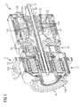
- FIG. 1 illustrated drive system for a wind turbine has a transmission unit 1 with a first eleventh and second planetary gear 12 in coaxial design.
- each planetary gear 11, 12 each comprise a ring gear 114, 124, a plurality of planet gears 113, 123, a planet carrier 112, 122 and a sun gear 111, 121.
- the transmission unit 1 is connected via an output shaft 16 of the transmission unit with a generator unit 2 and arranged together with this in a transmission housing 15.
- the transmission unit 1 is associated with an integrally formed on the planet carrier 112 of the first planetary gear 11 drive shaft having a connectable to a rotor shaft coupling flange 14 and is mounted on the planet carrier 112 of the first planetary gear 11.
- the planet carrier 112 of the first planetary gear 11 are arranged between two planet carrier cheeks and gear housing 15 bearings 115 and 116 which represent a first and a second main bearing of the transmission unit 1.
- the planet carrier 122 of the second planetary gear 12 is supported by two arranged between planet carrier cheeks and gear housing 15 bearings 125 and 126.
- the generator unit 2 comprises a stator 21 and a rotatably connected to a rotor hollow shaft 23 rotor 22. Radially between the output shaft 16 of the gear unit 1 and the hollow rotor shaft 23, a coupling or clamping connection 163 is arranged.
- a transmission housing nozzle 152 is arranged with a hollow cylindrical extension.
- the hollow cylindrical extension concentrically surrounds a generator-side end section of the output shaft 16 and forms a bearing seat for a bearing arrangement 161 arranged radially between the output shaft 16 and the hollow-cylindrical extension.
- the hollow-cylindrical extension is in turn surrounded concentrically by the rotor 22 and rotor hollow shaft 23.
- two outer bearing elements of the bearing assembly 161 are connected to the hollow cylindrical extension.
- a generator-side end portion of the output shaft 16 of the transmission unit 1 is concentrically surrounded by a hollow gear shaft 162 and rotatably connected thereto. With this transmission hollow shaft 162, two inner bearing elements of the bearing assembly 161 are connected. Thus, both the output shaft 16 of the gear unit 1 and the hollow rotor shaft 23 is mounted by means of the bearing assembly 161.
- the bearing arrangement 161 arranged in the hollow-cylindrical extension of the transmission housing nozzle 152 is axially centered on the rotor 22 of the generator unit 2.
- a pitch tube 17 is arranged within the output shaft 16 and the rotor hollow shaft 23, which extends axially over the entire drive system.
- the output shaft 16 of the transmission unit 1 axially about half surrounded by the generator hollow shaft 162.
- the bearing assembly 161 of the output shaft 16 within the hollow cylindrical extension of the housing socket 152 preferably comprises a double row bearing in X-arrangement.
- the hollow rotor shaft 23 and the output shaft 16 of the transmission unit 1 are mounted according to a particularly preferred embodiment exclusively by means of the bearing assembly 161 on the housing stub 152. A in the rear rotor hollow shaft bearing on a side facing away from the gear unit 1 end face of the generator unit 2 can therefore be omitted.
- a brake disk 231 is rotatably mounted in the present embodiment on the side remote from the gear unit 1 end face of the generator unit 2.
- the brake disc 231 is thus easy for maintenance accessible.
- One of the brake disc 233 associated caliper 24 is attached to the side facing away from the transmission unit 1 arranged housing cover.
- the gear hollow shaft 162 may be connected to the output shaft 16 of the transmission unit 1 by a toothed coupling with short or curved teeth.
- the transmission hollow shaft 162 may be connected to the output shaft 16 of the transmission unit 1 by an inner clamping set.
- the inner clamping set comprises at least in each case an outer ring and an inner ring, which have mutually corresponding conical contact surfaces and by means of a plurality of axially extending clamping screws can be braced against each other.
- the transmission hollow shaft 162 can be widened, for example, by a tension of the outer and inner ring. This then leads to a frictional connection between the hollow gear shaft 162 and the hollow rotor shaft 23.
- the hollow rotor shaft 23 can be connected, for example, by means of a feather key, which is aligned axially on the inner clamping set, with the hollow shaft 162.
- the hollow gear shaft 162 may be connected to the output shaft 16 of the gear unit 1 by an outer clamping set.
- an outer clamping set on the generator-side end portion of the output shaft 16 of the gear unit 1, a flange is provided for.
- About the outer clamping set can also be the rotor shaft 23 connected to the hollow gear shaft 162 and output shaft 16.
- the bearing assembly 161 of the output shaft 16 concentrically surrounding hollow cylindrical extension of the housing socket 152 is formed in the present embodiment to a arranged between the gear unit 1 and generator unit 2 Gephaseus interactionflansch 151.
- GeHous alternflansch 151 both a stator shell 211 of the generator unit 2 and the ring gear 124 of the second planetary gear 12 is mounted.
- the intermediate housing flange 151 has a bearing seat for a generator-side planet carrier bearing 126 of the second planetary gear stage 12.
- the Genzous interceptflansch 151 each have a Flanschfortsatz 1511, 1512, on which the stator shell 211 and the ring gear 124 of the second planetary gear 12 is mounted.
- FIG. 4 a variant of a Genosus interceptflansches 151 is shown, in which the stator shell 211 associated Flanschfortsatz 1512 and the ring gear 124 associated Flanschfortsatz 1511 are axially spaced apart.
- the gear housing 15 has a fully gimbal-shaped circumferentially symmetrical or partially symmetrical suspension 13 for connection to a supporting structural element of the wind turbine.
- This supporting structural element is for example a frame or a nacelle of the wind turbine.
- the second planetary gear 12 is dimensioned in terms of their translation so that when you select a divisible by 3 generator pole and optimum design for rated speed substantially identical outside diameter of stator of the generator unit 2 and ring gear 124 of the second Planet wheel 12 result.
- Generator-side bearings of the transmission unit 1 are designed to be electrically insulating. Thus, a flow of current from the transmission unit 1 into a rotor of the generator unit 2 can be avoided.
- An embodiment of the main bearing of the transmission unit 1 can continue to take place without consideration of supporting the following components.
- a torsional wave twist according to the invention by the fully gimbal suspension for the transmission unit 1 has become irrelevant damage.
- the generator unit 2 has in the present embodiment, 3 independent winding systems, which are connected to an in FIG. 5 shown full converter 3 are connected.
- the full converter 3 enables network dynamic decoupling and is connected via load disconnector 4 to the generator unit 2 on the one hand and on the other hand to a transformer 5 for power supply in a power grid 6.
- separately isolated generator windings are provided for each pole.
- the 3 independent winding systems are connected outside the transmission housing 15 surrounding the generator unit 2.
- the generator unit is configured 9 to 30-pole, preferably 12 to 24-pin.
- the full gimbal 13 is formed by a gear housing 15 fully radially surrounding ring support.
- the ring support 13 has in the circumferential direction a plurality of substantially equidistantly arranged bores 131, are inserted into the elastic bolt, each having a first end portion.
- the elastic bolts are connected to a corresponding torque arm on the supporting structural element 7 of the wind turbine.
- the corresponding torque arm also includes a ring member having in the circumferential direction substantially equidistantly arranged bores in which the elastic bolts are inserted with a second end portion.
- the corresponding torque arm according to the in FIG. 6 illustrated embodiment, two asymmetrically molded support arms 71, 72, which are each inserted with an end portion in a receptacle 73, 74 on the supporting structure element 7 and connected therewith.
- the elastic bolts of vollkardanischen suspension 13 are axially removable elastomeric bolt.
- the coupling flange 14 has accordingly FIG. 1 in the circumferential direction a plurality of substantially equidistantly arranged holes 141, are inserted into the axially removable elastomeric bolt, which are connected to a corresponding Rotorwellenkupplungsflansch.
- Additional units of the transmission unit 1 such as oil system, radiator and hydraulics, are advantageously mounted directly on the supporting structural element 7 of the wind turbine. About the vollkardanische suspension 13 and a flexible coupling between the rotor shaft and drive shaft of the transmission unit 1, the additional units are thus decoupled from the transmission housing 15.
- FIGS. 7 and 8 are each two ring segment supports 13a, 13b shown for partial comprehensive gimbal suspension of the drive system.
- the ring segment supports 13a, 13b each have a plurality of substantially equidistantly arranged bores 131 in the circumferential direction, into which elastic bolts are inserted.
- the elastic bolts with corresponding torque arms 71, 72 are connected to the supporting structure element 7 of the wind turbine.
- the corresponding torque arms 71, 72 are attached directly to the supporting structure element 7 of the wind turbine.
- a mounting capability remains as a conventional two-arm support, without the need for a main frame adaptation to the wind turbine is required. Since a Zwangskraft rejoin already exists, known Elastomerauflager can be used, which are preferably designed completely according to vibration damping criteria.
- the corresponding torque arms on the supporting structural element 7 each have a ring segment with circumferentially substantially equidistantly arranged bores 131.
- the elastic bolts are used, the same as in the embodiment accordingly FIG. 6 can be configured as axially removable elastomer bolt.
- symmetry axis of the torque arms and axis of rotation of the drive system intersect.
- the coupling flange may have a plurality of staggered rows of holes, in the bores of which axially removable elastomeric bolts are inserted.
- the coupling flange can be made smaller in terms of its outer diameter at the same bore spacings.
- the elastomeric bolts may have different rigidities adapted to the diameter and flange type.
- the coupling flange with smaller diameter compared to the suspension may be made of a harder material, while the suspension may be made of a softer material.
- the use of the drive system described is not limited to wind turbines, but also, for example, in mill drive systems conceivable in which the generator unit is replaced by a motor unit.
Landscapes
- Engineering & Computer Science (AREA)
- General Engineering & Computer Science (AREA)
- Mechanical Engineering (AREA)
- Life Sciences & Earth Sciences (AREA)
- Sustainable Development (AREA)
- Sustainable Energy (AREA)
- Chemical & Material Sciences (AREA)
- Combustion & Propulsion (AREA)
- Wind Motors (AREA)
- Connection Of Motors, Electrical Generators, Mechanical Devices, And The Like (AREA)
Priority Applications (3)
| Application Number | Priority Date | Filing Date | Title |
|---|---|---|---|
| EP11174846.3A EP2508777B1 (fr) | 2011-04-04 | 2011-07-21 | Système de propulsion pour une éolienne |
| US13/438,487 US9151275B2 (en) | 2011-04-04 | 2012-04-03 | Drive system for a wind turbine |
| CN201210098276.9A CN102734091B (zh) | 2011-04-04 | 2012-04-05 | 用于风力发电设备的传动系统 |
Applications Claiming Priority (2)
| Application Number | Priority Date | Filing Date | Title |
|---|---|---|---|
| EP11002782.8A EP2508754B1 (fr) | 2011-04-04 | 2011-04-04 | Système de transmission pour une éolienne |
| EP11174846.3A EP2508777B1 (fr) | 2011-04-04 | 2011-07-21 | Système de propulsion pour une éolienne |
Publications (2)
| Publication Number | Publication Date |
|---|---|
| EP2508777A1 true EP2508777A1 (fr) | 2012-10-10 |
| EP2508777B1 EP2508777B1 (fr) | 2014-04-02 |
Family
ID=44509841
Family Applications (2)
| Application Number | Title | Priority Date | Filing Date |
|---|---|---|---|
| EP11002782.8A Active EP2508754B1 (fr) | 2011-04-04 | 2011-04-04 | Système de transmission pour une éolienne |
| EP11174846.3A Active EP2508777B1 (fr) | 2011-04-04 | 2011-07-21 | Système de propulsion pour une éolienne |
Family Applications Before (1)
| Application Number | Title | Priority Date | Filing Date |
|---|---|---|---|
| EP11002782.8A Active EP2508754B1 (fr) | 2011-04-04 | 2011-04-04 | Système de transmission pour une éolienne |
Country Status (5)
| Country | Link |
|---|---|
| US (2) | US8632437B2 (fr) |
| EP (2) | EP2508754B1 (fr) |
| CN (2) | CN102734091B (fr) |
| ES (1) | ES2460691T3 (fr) |
| PL (1) | PL2508754T3 (fr) |
Cited By (1)
| Publication number | Priority date | Publication date | Assignee | Title |
|---|---|---|---|---|
| EP2933483A1 (fr) | 2014-04-15 | 2015-10-21 | Siemens Aktiengesellschaft | Système d'entraînement d'une éolienne |
Families Citing this family (34)
| Publication number | Priority date | Publication date | Assignee | Title |
|---|---|---|---|---|
| NL2008103C2 (en) * | 2011-03-14 | 2013-07-15 | Nestor Man Consultants B V | Transmission. |
| SE537562C2 (sv) * | 2011-03-26 | 2015-06-16 | Indexator Rotator Sys Ab | Anordning vid en rotator |
| PL2508754T3 (pl) * | 2011-04-04 | 2016-10-31 | System napędowy dla siłowni wiatrowej | |
| EP2573386B1 (fr) | 2011-09-26 | 2014-10-29 | Siemens Aktiengesellschaft | Système de transmission pour une éolienne |
| DE102011085299A1 (de) | 2011-10-27 | 2013-05-02 | Siemens Aktiengesellschaft | Getriebe für industrielle Anwendungen oder Windkraftanlagen |
| US9103326B2 (en) * | 2012-07-31 | 2015-08-11 | General Electric Company | Wind turbine bedplate support frame |
| ES2654669T3 (es) | 2014-02-21 | 2018-02-14 | Siemens Aktiengesellschaft | Máquina con un ramal de accionamiento |
| EP2975260B2 (fr) * | 2014-07-18 | 2021-12-22 | Siemens Gamesa Renewable Energy A/S | Agencement de suspension de générateur |
| EP2975299A1 (fr) | 2014-07-18 | 2016-01-20 | Siemens Aktiengesellschaft | Palier à glissement pour support épicycloïdal |
| US9856966B2 (en) | 2014-08-27 | 2018-01-02 | General Electric Company | Drivetrain assembly for a wind turbine |
| ES2733606T3 (es) * | 2015-02-26 | 2019-12-02 | Flender Gmbh | Disposición con sistema FOFW |
| DK178869B1 (en) * | 2015-09-16 | 2017-04-10 | Envision Energy Denmark Aps | Wind turbine with a gear unit and an installation method and an upgrading method thereof |
| DE102015217906A1 (de) * | 2015-09-18 | 2017-03-23 | Zf Friedrichshafen Ag | Mehrstufiges Planetengetriebe für eine Windkraftanlage mit spezieller Schmierölführung |
| JP1556890S (fr) * | 2015-10-19 | 2016-08-22 | ||
| DE102015220996A1 (de) * | 2015-10-27 | 2017-04-27 | Zf Friedrichshafen Ag | Zweistückige Drehmomentstütze |
| TWI599143B (zh) * | 2016-07-19 | 2017-09-11 | Zhen-zhi YE | Multi-function powerhouse |
| EP3284975B1 (fr) | 2016-08-19 | 2020-02-26 | Flender GmbH | Axe planetaire |
| AU201711758S (en) * | 2016-10-14 | 2017-04-10 | Sew Eurodrive Gmbh & Co | Gearboxes for electric motors and generators |
| US10619721B2 (en) * | 2017-07-21 | 2020-04-14 | General Electric Company | Drivetrain assembly for a wind turbine |
| DE102017008878A1 (de) * | 2017-09-21 | 2019-03-21 | Imo Holding Gmbh | Hauptlagereinheit für die Rotorwelle einer Windkraftanlage und Windkraftanlage |
| EP3502517A1 (fr) | 2017-12-19 | 2019-06-26 | Flender GmbH | Engrenage planétaire à structure de support améliorée, groupe motopropulseur et éolienne |
| DE102018004763A1 (de) * | 2017-12-20 | 2019-06-27 | Senvion Gmbh | Windenergieanlage mit Triebstrang |
| DE102018002553A1 (de) * | 2018-03-28 | 2019-10-02 | Senvion Gmbh | Maschinenträger für Windenergieanlagen |
| DE102018008034A1 (de) * | 2018-10-11 | 2020-04-16 | Senvion Gmbh | Windenergieanlage mit Triebstrang |
| EP3653907A1 (fr) | 2018-11-15 | 2020-05-20 | ZF Friedrichshafen AG | Caisson de stockage pour éoliennes |
| CN109654178A (zh) * | 2018-11-29 | 2019-04-19 | 安徽国防科技职业学院 | 一种新型兆瓦级风电齿轮箱传动系统 |
| CN109555818A (zh) * | 2018-12-12 | 2019-04-02 | 重庆久和豪贝机械有限公司 | 一种行星轮支撑装置 |
| EP3715629A1 (fr) | 2019-03-27 | 2020-09-30 | General Electric Company | Système et procédé permettant de réduire la largeur de transport d'une boîte de vitesses pour une éolienne |
| US11009118B1 (en) * | 2019-10-24 | 2021-05-18 | John Matthew Hawkins | Epicyclic gearing torque reduction mechanism |
| EP3992452A1 (fr) * | 2020-10-28 | 2022-05-04 | General Electric Renovables España S.L. | Nacelle pour éolienne |
| CN115395708B (zh) * | 2021-05-25 | 2023-12-08 | 北京金风科创风电设备有限公司 | 发电装置及其维护方法和风力发电机组 |
| EP4102061A1 (fr) * | 2021-06-10 | 2022-12-14 | Siemens Gamesa Renewable Energy A/S | Ensemble de support |
| CN113417989B (zh) * | 2021-06-19 | 2022-06-21 | 山东双冠机械有限公司 | 一种gtf发动机齿轮箱固定装置 |
| DE102021214132B4 (de) | 2021-12-10 | 2023-07-13 | Zf Friedrichshafen Ag | Getriebe und Generator mit Zwischenwelle |
Citations (11)
| Publication number | Priority date | Publication date | Assignee | Title |
|---|---|---|---|---|
| DE29609794U1 (de) * | 1996-06-03 | 1996-08-22 | Aerodyn Gmbh | Getriebe-Generator-Kombination |
| EP1000355A1 (fr) | 1997-07-25 | 2000-05-17 | Coulter International Corp. | Procede de denombrement des leucocytes et d'evaluation de la concentration en hemoglobine du sang |
| EP1100278A2 (fr) | 1999-11-11 | 2001-05-16 | Tektronix, Inc. | Modélisation en temps réel du comportement du système de vision humaine |
| GB2405455A (en) * | 2003-09-01 | 2005-03-02 | Dbt Gmbh | Drive system for chain sprockets of chain drives. |
| EP1717489A2 (fr) * | 2005-04-29 | 2006-11-02 | Pujol Muntala S.A. | Engrenage de multiplication ou de réduction du type épicycloïdale pour utilisation dans des éoliennes et similaires |
| CN101363407A (zh) * | 2008-09-12 | 2009-02-11 | 三一电气有限责任公司 | 一种风力发电机组 |
| EP2031273A2 (fr) | 2007-08-27 | 2009-03-04 | General Electric Company | Ensemble de transmission à entraînement forcé à vitesse moyenne intégrée |
| JP2009250213A (ja) * | 2008-04-10 | 2009-10-29 | Mitsubishi Heavy Ind Ltd | 風力発電装置 |
| WO2010005790A2 (fr) * | 2008-07-10 | 2010-01-14 | General Electric Company | Système de génération d'énergie à éolienne |
| EP2216547A2 (fr) * | 2009-01-16 | 2010-08-11 | General Electric Company | Ensemble de transmission à entraînement forcé compact pour éolienne |
| EP2295147A1 (fr) | 2009-09-10 | 2011-03-16 | Siemens Aktiengesellschaft | Système d'entraînement de moulin |
Family Cites Families (35)
| Publication number | Priority date | Publication date | Assignee | Title |
|---|---|---|---|---|
| US2814352A (en) * | 1952-05-17 | 1957-11-26 | Daimler Benz Ag | Engine suspension for motor vehicles |
| DE1198699B (de) * | 1962-07-21 | 1965-08-12 | Wagner Hochdruck Dampfturbinen | Antriebsanlage fuer Schiffe mit mehreren Antriebsmaschinen |
| GB1448059A (en) * | 1974-04-18 | 1976-09-02 | Vickers Ltd | Gears |
| DE2506160C3 (de) * | 1975-02-14 | 1978-04-13 | Alberto 8136 Percha Kling | Windkraftwerk |
| US4096769A (en) * | 1975-07-11 | 1978-06-27 | Kabushiki Kaisha Toyota Chuo Kenkyusho | Planetary gear type transmission |
| DE2736438A1 (de) * | 1977-08-10 | 1979-02-22 | Mannesmann Ag | Planetengetriebe mit lastausgleich |
| US5873560A (en) * | 1996-05-02 | 1999-02-23 | Chrysler Corporation | Gimbal support system with uni-directional roll stiffness |
| US6030177A (en) * | 1998-12-18 | 2000-02-29 | Sikorsky Aircraft Corporation | Drive system for a variable diameter tilt rotor |
| DE19916453A1 (de) | 1999-04-12 | 2000-10-19 | Flender A F & Co | Windkraftanlage |
| EP1311759B1 (fr) * | 2000-08-15 | 2012-11-07 | ZF Wind Power Antwerpen NV | Ensemble d'entrainement d'eolienne |
| DE10114609A1 (de) * | 2001-03-23 | 2002-09-26 | Enron Wind Gmbh | Drehmomentübertragungsvorrichtung für eine Windkraftanlage |
| US6956300B2 (en) * | 2003-08-04 | 2005-10-18 | Andrew Roman Gizara | Gimbal-mounted hydroelectric turbine |
| DK1508692T4 (da) | 2003-08-14 | 2016-08-22 | W2E Wind To Energy Gmbh | Vindenergikonverter med et med et indre rum forsynet rotornav |
| DE10360693A1 (de) * | 2003-12-19 | 2005-07-14 | Winergy Ag | Planetengetriebe, insbesondere für Windkraftanlagen |
| EP1593867B1 (fr) | 2004-05-04 | 2008-12-17 | Franz Mitsch | Accouplement avec des éléments de portage prestressés |
| DE102006043179A1 (de) | 2006-09-14 | 2008-03-27 | Siemens Ag | Mühle zum Mahlen von grobem, steinartigem Schüttgut mit achsparallelem Antrieb |
| US7621843B2 (en) * | 2007-01-17 | 2009-11-24 | General Electric Company | Apparatus for restraining axial movement of a ring gear in a gearbox for a wind turbine |
| DE102007012408A1 (de) | 2007-03-15 | 2008-09-18 | Aerodyn Engineering Gmbh | Windenergieanlagen mit lastübertragenden Bauteilen |
| TW200907197A (en) * | 2007-06-08 | 2009-02-16 | Sequal Technologies Inc | Compressor vibration isolation mount and method of use |
| DE102007057608A1 (de) | 2007-11-28 | 2009-06-04 | A. Friedr. Flender Ag | Stirnradgetriebe |
| BE1017866A3 (nl) * | 2007-12-06 | 2009-09-01 | Hansen Transmissions Int | Windturbineaandrijving. |
| ES2554538T3 (es) * | 2007-12-21 | 2015-12-21 | Vestas Wind Systems A/S | Tren de transmisión para una turbina eólica |
| DK2323771T3 (da) | 2008-08-22 | 2012-07-16 | Smidth As F L | Tunglastdrivarrangement og mølle drevet dermed |
| US8075442B2 (en) * | 2008-09-05 | 2011-12-13 | General Electric Company | System and assembly for power transmission and generation in a wind turbine |
| US7884493B2 (en) * | 2008-09-30 | 2011-02-08 | General Electric Company | Wind turbine generator brake and grounding brush arrangement |
| DE102008063868B3 (de) | 2008-12-19 | 2010-06-10 | Winergy Ag | Planetengetriebe für eine Windkraftanlage |
| CN201358892Y (zh) * | 2009-03-09 | 2009-12-09 | 大连华锐股份有限公司 | 风力发电增速齿轮箱 |
| US8376708B2 (en) | 2009-06-30 | 2013-02-19 | General Electric Company | Drivetrain system for a wind turbine generator and method of assembling the same |
| CN201656699U (zh) * | 2010-01-19 | 2010-11-24 | 上海摩根碳制品有限公司 | 一种风力发电机用接地电刷 |
| EP2366988A1 (fr) | 2010-03-19 | 2011-09-21 | Winergy AG | Procédé et dispositif de détection de couple dans un engrenage au moyen d'un capteur de vibrations |
| EP2372148B1 (fr) | 2010-03-31 | 2012-05-09 | Winergy AG | Dispositif d'entraînement pour une éolienne |
| ES2393850T3 (es) | 2010-04-30 | 2012-12-28 | Winergy Ag | Engranaje planetario (epicicloidal) para un aerogenerador |
| EP2388498B1 (fr) | 2010-05-21 | 2012-09-19 | Winergy AG | Transmission pour une éolienne |
| DK2457663T3 (en) | 2010-11-29 | 2014-03-17 | Siemens Ag | Gear Motor for a mill-drivanlæg |
| PL2508754T3 (pl) * | 2011-04-04 | 2016-10-31 | System napędowy dla siłowni wiatrowej |
-
2011
- 2011-04-04 PL PL11002782.8T patent/PL2508754T3/pl unknown
- 2011-04-04 EP EP11002782.8A patent/EP2508754B1/fr active Active
- 2011-07-21 ES ES11174846.3T patent/ES2460691T3/es active Active
- 2011-07-21 EP EP11174846.3A patent/EP2508777B1/fr active Active
-
2012
- 2012-04-03 US US13/438,506 patent/US8632437B2/en active Active
- 2012-04-03 US US13/438,487 patent/US9151275B2/en not_active Expired - Fee Related
- 2012-04-05 CN CN201210098276.9A patent/CN102734091B/zh not_active Expired - Fee Related
- 2012-04-05 CN CN201210098155.4A patent/CN102734090B/zh not_active Expired - Fee Related
Patent Citations (11)
| Publication number | Priority date | Publication date | Assignee | Title |
|---|---|---|---|---|
| DE29609794U1 (de) * | 1996-06-03 | 1996-08-22 | Aerodyn Gmbh | Getriebe-Generator-Kombination |
| EP1000355A1 (fr) | 1997-07-25 | 2000-05-17 | Coulter International Corp. | Procede de denombrement des leucocytes et d'evaluation de la concentration en hemoglobine du sang |
| EP1100278A2 (fr) | 1999-11-11 | 2001-05-16 | Tektronix, Inc. | Modélisation en temps réel du comportement du système de vision humaine |
| GB2405455A (en) * | 2003-09-01 | 2005-03-02 | Dbt Gmbh | Drive system for chain sprockets of chain drives. |
| EP1717489A2 (fr) * | 2005-04-29 | 2006-11-02 | Pujol Muntala S.A. | Engrenage de multiplication ou de réduction du type épicycloïdale pour utilisation dans des éoliennes et similaires |
| EP2031273A2 (fr) | 2007-08-27 | 2009-03-04 | General Electric Company | Ensemble de transmission à entraînement forcé à vitesse moyenne intégrée |
| JP2009250213A (ja) * | 2008-04-10 | 2009-10-29 | Mitsubishi Heavy Ind Ltd | 風力発電装置 |
| WO2010005790A2 (fr) * | 2008-07-10 | 2010-01-14 | General Electric Company | Système de génération d'énergie à éolienne |
| CN101363407A (zh) * | 2008-09-12 | 2009-02-11 | 三一电气有限责任公司 | 一种风力发电机组 |
| EP2216547A2 (fr) * | 2009-01-16 | 2010-08-11 | General Electric Company | Ensemble de transmission à entraînement forcé compact pour éolienne |
| EP2295147A1 (fr) | 2009-09-10 | 2011-03-16 | Siemens Aktiengesellschaft | Système d'entraînement de moulin |
Cited By (2)
| Publication number | Priority date | Publication date | Assignee | Title |
|---|---|---|---|---|
| EP2933483A1 (fr) | 2014-04-15 | 2015-10-21 | Siemens Aktiengesellschaft | Système d'entraînement d'une éolienne |
| US10316826B2 (en) | 2014-04-15 | 2019-06-11 | Siemens Aktiengesellschaft | Drive system of a wind turbine |
Also Published As
| Publication number | Publication date |
|---|---|
| EP2508777B1 (fr) | 2014-04-02 |
| EP2508754B1 (fr) | 2016-03-30 |
| PL2508754T3 (pl) | 2016-10-31 |
| CN102734090A (zh) | 2012-10-17 |
| US20130095972A1 (en) | 2013-04-18 |
| US9151275B2 (en) | 2015-10-06 |
| CN102734091A (zh) | 2012-10-17 |
| CN102734090B (zh) | 2015-12-02 |
| US20130088016A1 (en) | 2013-04-11 |
| EP2508754A1 (fr) | 2012-10-10 |
| ES2460691T3 (es) | 2014-05-14 |
| US8632437B2 (en) | 2014-01-21 |
| CN102734091B (zh) | 2014-09-17 |
Similar Documents
| Publication | Publication Date | Title |
|---|---|---|
| EP2508777B1 (fr) | Système de propulsion pour une éolienne | |
| EP2541058B1 (fr) | Système de propulsion pour une éolienne | |
| EP2573386B1 (fr) | Système de transmission pour une éolienne | |
| EP2541096A1 (fr) | Système de propulsion pour une éolienne | |
| EP2097641B1 (fr) | Transmission d'éolienne à couple divisé | |
| EP2379879B1 (fr) | Ensemble génératrice pour éolienne | |
| WO2015158753A1 (fr) | Système d'entraînement d'une éolienne | |
| DE102012107419A1 (de) | Anstellwinkeländerungsmechanismus für offenliegenen Rotoraufbau | |
| EP2710271A1 (fr) | Unité palier, notamment pour une éolienne | |
| EP1457673B1 (fr) | Disposition de support de rotor d'éolienne | |
| EP2207984A2 (fr) | Desaccouplement de l'arbre d'entrainement et de l'arbre entraine par une transmission a deux etages d'une eolienne | |
| DE102011008029A1 (de) | Windenergieanlage | |
| DE102011106535B4 (de) | Antriebsstrang einer Strömungskraftanlage | |
| EP2545994A1 (fr) | Agencement pour un broyeur à rouleaux | |
| EP2525091B1 (fr) | Système d'entraînement pour une éolienne | |
| DE102012221255A1 (de) | Lagereinheit für eine Windkraftmaschine | |
| DE102009008340A1 (de) | Strömungskraftanlage | |
| EP2514076A1 (fr) | Ensemble génératrice pour une éolienne | |
| EP2372148B1 (fr) | Dispositif d'entraînement pour une éolienne | |
| DE102012205946A1 (de) | Getriebeeinrichtung, insbesondere für eine Windkraftanlage | |
| WO2010121586A2 (fr) | Chaîne cinématique pour éolienne, nacelle d'éolienne, éolienne et parc d'éoliennes ainsi que conteneur standard | |
| DE102019119473A1 (de) | Triebstranganordnung | |
| EP2836707B1 (fr) | Eolienne avec un generateur inversé du type outrunner | |
| EP4047228A1 (fr) | Agencement des roulements, pignon de générateur, centrale éolienne et produit programme informatique | |
| WO2023165769A1 (fr) | Ensemble engrenage planétaire comprenant un arbre solaire monté dans/sur le porte-satellites, transmission industrielle et utilisation correspondantes |
Legal Events
| Date | Code | Title | Description |
|---|---|---|---|
| PUAI | Public reference made under article 153(3) epc to a published international application that has entered the european phase |
Free format text: ORIGINAL CODE: 0009012 |
|
| AK | Designated contracting states |
Kind code of ref document: A1 Designated state(s): AL AT BE BG CH CY CZ DE DK EE ES FI FR GB GR HR HU IE IS IT LI LT LU LV MC MK MT NL NO PL PT RO RS SE SI SK SM TR |
|
| AX | Request for extension of the european patent |
Extension state: BA ME |
|
| 17P | Request for examination filed |
Effective date: 20121105 |
|
| RAP1 | Party data changed (applicant data changed or rights of an application transferred) |
Owner name: SIEMENS AKTIENGESELLSCHAFT |
|
| GRAP | Despatch of communication of intention to grant a patent |
Free format text: ORIGINAL CODE: EPIDOSNIGR1 |
|
| INTG | Intention to grant announced |
Effective date: 20130521 |
|
| GRAP | Despatch of communication of intention to grant a patent |
Free format text: ORIGINAL CODE: EPIDOSNIGR1 |
|
| INTG | Intention to grant announced |
Effective date: 20130917 |
|
| GRAS | Grant fee paid |
Free format text: ORIGINAL CODE: EPIDOSNIGR3 |
|
| GRAA | (expected) grant |
Free format text: ORIGINAL CODE: 0009210 |
|
| AK | Designated contracting states |
Kind code of ref document: B1 Designated state(s): AL AT BE BG CH CY CZ DE DK EE ES FI FR GB GR HR HU IE IS IT LI LT LU LV MC MK MT NL NO PL PT RO RS SE SI SK SM TR |
|
| REG | Reference to a national code |
Ref country code: GB Ref legal event code: FG4D Free format text: NOT ENGLISH |
|
| REG | Reference to a national code |
Ref country code: CH Ref legal event code: EP Ref country code: AT Ref legal event code: REF Ref document number: 660325 Country of ref document: AT Kind code of ref document: T Effective date: 20140415 |
|
| REG | Reference to a national code |
Ref country code: IE Ref legal event code: FG4D Free format text: LANGUAGE OF EP DOCUMENT: GERMAN |
|
| REG | Reference to a national code |
Ref country code: ES Ref legal event code: FG2A Ref document number: 2460691 Country of ref document: ES Kind code of ref document: T3 Effective date: 20140514 |
|
| REG | Reference to a national code |
Ref country code: DE Ref legal event code: R096 Ref document number: 502011002580 Country of ref document: DE Effective date: 20140515 |
|
| REG | Reference to a national code |
Ref country code: SE Ref legal event code: TRGR |
|
| REG | Reference to a national code |
Ref country code: NL Ref legal event code: VDEP Effective date: 20140402 |
|
| REG | Reference to a national code |
Ref country code: LT Ref legal event code: MG4D |
|
| PG25 | Lapsed in a contracting state [announced via postgrant information from national office to epo] |
Ref country code: CY Free format text: LAPSE BECAUSE OF FAILURE TO SUBMIT A TRANSLATION OF THE DESCRIPTION OR TO PAY THE FEE WITHIN THE PRESCRIBED TIME-LIMIT Effective date: 20140402 Ref country code: LT Free format text: LAPSE BECAUSE OF FAILURE TO SUBMIT A TRANSLATION OF THE DESCRIPTION OR TO PAY THE FEE WITHIN THE PRESCRIBED TIME-LIMIT Effective date: 20140402 Ref country code: CZ Free format text: LAPSE BECAUSE OF FAILURE TO SUBMIT A TRANSLATION OF THE DESCRIPTION OR TO PAY THE FEE WITHIN THE PRESCRIBED TIME-LIMIT Effective date: 20140402 Ref country code: FI Free format text: LAPSE BECAUSE OF FAILURE TO SUBMIT A TRANSLATION OF THE DESCRIPTION OR TO PAY THE FEE WITHIN THE PRESCRIBED TIME-LIMIT Effective date: 20140402 Ref country code: BG Free format text: LAPSE BECAUSE OF FAILURE TO SUBMIT A TRANSLATION OF THE DESCRIPTION OR TO PAY THE FEE WITHIN THE PRESCRIBED TIME-LIMIT Effective date: 20140702 Ref country code: NO Free format text: LAPSE BECAUSE OF FAILURE TO SUBMIT A TRANSLATION OF THE DESCRIPTION OR TO PAY THE FEE WITHIN THE PRESCRIBED TIME-LIMIT Effective date: 20140702 Ref country code: NL Free format text: LAPSE BECAUSE OF FAILURE TO SUBMIT A TRANSLATION OF THE DESCRIPTION OR TO PAY THE FEE WITHIN THE PRESCRIBED TIME-LIMIT Effective date: 20140402 Ref country code: GR Free format text: LAPSE BECAUSE OF FAILURE TO SUBMIT A TRANSLATION OF THE DESCRIPTION OR TO PAY THE FEE WITHIN THE PRESCRIBED TIME-LIMIT Effective date: 20140703 Ref country code: IS Free format text: LAPSE BECAUSE OF FAILURE TO SUBMIT A TRANSLATION OF THE DESCRIPTION OR TO PAY THE FEE WITHIN THE PRESCRIBED TIME-LIMIT Effective date: 20140802 |
|
| PG25 | Lapsed in a contracting state [announced via postgrant information from national office to epo] |
Ref country code: LV Free format text: LAPSE BECAUSE OF FAILURE TO SUBMIT A TRANSLATION OF THE DESCRIPTION OR TO PAY THE FEE WITHIN THE PRESCRIBED TIME-LIMIT Effective date: 20140402 Ref country code: HR Free format text: LAPSE BECAUSE OF FAILURE TO SUBMIT A TRANSLATION OF THE DESCRIPTION OR TO PAY THE FEE WITHIN THE PRESCRIBED TIME-LIMIT Effective date: 20140402 Ref country code: PL Free format text: LAPSE BECAUSE OF FAILURE TO SUBMIT A TRANSLATION OF THE DESCRIPTION OR TO PAY THE FEE WITHIN THE PRESCRIBED TIME-LIMIT Effective date: 20140402 Ref country code: RS Free format text: LAPSE BECAUSE OF FAILURE TO SUBMIT A TRANSLATION OF THE DESCRIPTION OR TO PAY THE FEE WITHIN THE PRESCRIBED TIME-LIMIT Effective date: 20140402 |
|
| PG25 | Lapsed in a contracting state [announced via postgrant information from national office to epo] |
Ref country code: PT Free format text: LAPSE BECAUSE OF FAILURE TO SUBMIT A TRANSLATION OF THE DESCRIPTION OR TO PAY THE FEE WITHIN THE PRESCRIBED TIME-LIMIT Effective date: 20140804 |
|
| REG | Reference to a national code |
Ref country code: DE Ref legal event code: R097 Ref document number: 502011002580 Country of ref document: DE |
|
| PG25 | Lapsed in a contracting state [announced via postgrant information from national office to epo] |
Ref country code: DK Free format text: LAPSE BECAUSE OF FAILURE TO SUBMIT A TRANSLATION OF THE DESCRIPTION OR TO PAY THE FEE WITHIN THE PRESCRIBED TIME-LIMIT Effective date: 20140402 Ref country code: EE Free format text: LAPSE BECAUSE OF FAILURE TO SUBMIT A TRANSLATION OF THE DESCRIPTION OR TO PAY THE FEE WITHIN THE PRESCRIBED TIME-LIMIT Effective date: 20140402 Ref country code: RO Free format text: LAPSE BECAUSE OF FAILURE TO SUBMIT A TRANSLATION OF THE DESCRIPTION OR TO PAY THE FEE WITHIN THE PRESCRIBED TIME-LIMIT Effective date: 20140402 Ref country code: SK Free format text: LAPSE BECAUSE OF FAILURE TO SUBMIT A TRANSLATION OF THE DESCRIPTION OR TO PAY THE FEE WITHIN THE PRESCRIBED TIME-LIMIT Effective date: 20140402 |
|
| PLBE | No opposition filed within time limit |
Free format text: ORIGINAL CODE: 0009261 |
|
| STAA | Information on the status of an ep patent application or granted ep patent |
Free format text: STATUS: NO OPPOSITION FILED WITHIN TIME LIMIT |
|
| PG25 | Lapsed in a contracting state [announced via postgrant information from national office to epo] |
Ref country code: LU Free format text: LAPSE BECAUSE OF FAILURE TO SUBMIT A TRANSLATION OF THE DESCRIPTION OR TO PAY THE FEE WITHIN THE PRESCRIBED TIME-LIMIT Effective date: 20140721 |
|
| REG | Reference to a national code |
Ref country code: CH Ref legal event code: PL |
|
| 26N | No opposition filed |
Effective date: 20150106 |
|
| REG | Reference to a national code |
Ref country code: DE Ref legal event code: R097 Ref document number: 502011002580 Country of ref document: DE Effective date: 20150106 |
|
| REG | Reference to a national code |
Ref country code: IE Ref legal event code: MM4A |
|
| PG25 | Lapsed in a contracting state [announced via postgrant information from national office to epo] |
Ref country code: LI Free format text: LAPSE BECAUSE OF NON-PAYMENT OF DUE FEES Effective date: 20140731 Ref country code: CH Free format text: LAPSE BECAUSE OF NON-PAYMENT OF DUE FEES Effective date: 20140731 |
|
| PG25 | Lapsed in a contracting state [announced via postgrant information from national office to epo] |
Ref country code: RS Free format text: LAPSE BECAUSE OF FAILURE TO SUBMIT A TRANSLATION OF THE DESCRIPTION OR TO PAY THE FEE WITHIN THE PRESCRIBED TIME-LIMIT Effective date: 20141119 |
|
| PG25 | Lapsed in a contracting state [announced via postgrant information from national office to epo] |
Ref country code: SI Free format text: LAPSE BECAUSE OF FAILURE TO SUBMIT A TRANSLATION OF THE DESCRIPTION OR TO PAY THE FEE WITHIN THE PRESCRIBED TIME-LIMIT Effective date: 20140402 |
|
| PG25 | Lapsed in a contracting state [announced via postgrant information from national office to epo] |
Ref country code: IE Free format text: LAPSE BECAUSE OF NON-PAYMENT OF DUE FEES Effective date: 20140721 |
|
| PG25 | Lapsed in a contracting state [announced via postgrant information from national office to epo] |
Ref country code: MC Free format text: LAPSE BECAUSE OF FAILURE TO SUBMIT A TRANSLATION OF THE DESCRIPTION OR TO PAY THE FEE WITHIN THE PRESCRIBED TIME-LIMIT Effective date: 20140402 Ref country code: SM Free format text: LAPSE BECAUSE OF FAILURE TO SUBMIT A TRANSLATION OF THE DESCRIPTION OR TO PAY THE FEE WITHIN THE PRESCRIBED TIME-LIMIT Effective date: 20140402 |
|
| PG25 | Lapsed in a contracting state [announced via postgrant information from national office to epo] |
Ref country code: MT Free format text: LAPSE BECAUSE OF FAILURE TO SUBMIT A TRANSLATION OF THE DESCRIPTION OR TO PAY THE FEE WITHIN THE PRESCRIBED TIME-LIMIT Effective date: 20140402 |
|
| REG | Reference to a national code |
Ref country code: FR Ref legal event code: PLFP Year of fee payment: 6 |
|
| PG25 | Lapsed in a contracting state [announced via postgrant information from national office to epo] |
Ref country code: HU Free format text: LAPSE BECAUSE OF FAILURE TO SUBMIT A TRANSLATION OF THE DESCRIPTION OR TO PAY THE FEE WITHIN THE PRESCRIBED TIME-LIMIT; INVALID AB INITIO Effective date: 20110721 Ref country code: TR Free format text: LAPSE BECAUSE OF FAILURE TO SUBMIT A TRANSLATION OF THE DESCRIPTION OR TO PAY THE FEE WITHIN THE PRESCRIBED TIME-LIMIT Effective date: 20140402 Ref country code: BE Free format text: LAPSE BECAUSE OF FAILURE TO SUBMIT A TRANSLATION OF THE DESCRIPTION OR TO PAY THE FEE WITHIN THE PRESCRIBED TIME-LIMIT Effective date: 20140731 |
|
| REG | Reference to a national code |
Ref country code: FR Ref legal event code: PLFP Year of fee payment: 7 |
|
| REG | Reference to a national code |
Ref country code: AT Ref legal event code: MM01 Ref document number: 660325 Country of ref document: AT Kind code of ref document: T Effective date: 20160721 |
|
| PG25 | Lapsed in a contracting state [announced via postgrant information from national office to epo] |
Ref country code: AT Free format text: LAPSE BECAUSE OF NON-PAYMENT OF DUE FEES Effective date: 20160721 |
|
| PG25 | Lapsed in a contracting state [announced via postgrant information from national office to epo] |
Ref country code: MK Free format text: LAPSE BECAUSE OF FAILURE TO SUBMIT A TRANSLATION OF THE DESCRIPTION OR TO PAY THE FEE WITHIN THE PRESCRIBED TIME-LIMIT Effective date: 20140402 |
|
| REG | Reference to a national code |
Ref country code: FR Ref legal event code: PLFP Year of fee payment: 8 |
|
| PG25 | Lapsed in a contracting state [announced via postgrant information from national office to epo] |
Ref country code: AL Free format text: LAPSE BECAUSE OF FAILURE TO SUBMIT A TRANSLATION OF THE DESCRIPTION OR TO PAY THE FEE WITHIN THE PRESCRIBED TIME-LIMIT Effective date: 20140402 |
|
| REG | Reference to a national code |
Ref country code: DE Ref legal event code: R081 Ref document number: 502011002580 Country of ref document: DE Owner name: FLENDER GMBH, DE Free format text: FORMER OWNER: SIEMENS AG, 80333 MUENCHEN, DE |
|
| REG | Reference to a national code |
Ref country code: GB Ref legal event code: 732E Free format text: REGISTERED BETWEEN 20201210 AND 20201216 |
|
| REG | Reference to a national code |
Ref country code: ES Ref legal event code: PC2A Owner name: FLENDER GMBH Effective date: 20210223 |
|
| REG | Reference to a national code |
Ref country code: DE Ref legal event code: R082 Ref document number: 502011002580 Country of ref document: DE Representative=s name: MICHALSKI HUETTERMANN & PARTNER PATENTANWAELTE, DE |
|
| PGFP | Annual fee paid to national office [announced via postgrant information from national office to epo] |
Ref country code: IT Payment date: 20210727 Year of fee payment: 11 Ref country code: FR Payment date: 20210728 Year of fee payment: 11 |
|
| PGFP | Annual fee paid to national office [announced via postgrant information from national office to epo] |
Ref country code: SE Payment date: 20210721 Year of fee payment: 11 Ref country code: ES Payment date: 20210927 Year of fee payment: 11 |
|
| PGFP | Annual fee paid to national office [announced via postgrant information from national office to epo] |
Ref country code: GB Payment date: 20220721 Year of fee payment: 12 Ref country code: DE Payment date: 20220628 Year of fee payment: 12 |
|
| REG | Reference to a national code |
Ref country code: SE Ref legal event code: EUG |
|
| PG25 | Lapsed in a contracting state [announced via postgrant information from national office to epo] |
Ref country code: SE Free format text: LAPSE BECAUSE OF NON-PAYMENT OF DUE FEES Effective date: 20220722 Ref country code: FR Free format text: LAPSE BECAUSE OF NON-PAYMENT OF DUE FEES Effective date: 20220731 |
|
| REG | Reference to a national code |
Ref country code: ES Ref legal event code: FD2A Effective date: 20230901 |
|
| PG25 | Lapsed in a contracting state [announced via postgrant information from national office to epo] |
Ref country code: ES Free format text: LAPSE BECAUSE OF NON-PAYMENT OF DUE FEES Effective date: 20220722 |
|
| REG | Reference to a national code |
Ref country code: DE Ref legal event code: R119 Ref document number: 502011002580 Country of ref document: DE |
|
| GBPC | Gb: european patent ceased through non-payment of renewal fee |
Effective date: 20230721 |
|
| PG25 | Lapsed in a contracting state [announced via postgrant information from national office to epo] |
Ref country code: DE Free format text: LAPSE BECAUSE OF NON-PAYMENT OF DUE FEES Effective date: 20240201 Ref country code: GB Free format text: LAPSE BECAUSE OF NON-PAYMENT OF DUE FEES Effective date: 20230721 |