EP2507137B1 - Mit einem deckel verschliessbarer flaschenkasten - Google Patents
Mit einem deckel verschliessbarer flaschenkasten Download PDFInfo
- Publication number
- EP2507137B1 EP2507137B1 EP11788900.6A EP11788900A EP2507137B1 EP 2507137 B1 EP2507137 B1 EP 2507137B1 EP 11788900 A EP11788900 A EP 11788900A EP 2507137 B1 EP2507137 B1 EP 2507137B1
- Authority
- EP
- European Patent Office
- Prior art keywords
- lid
- handle
- container
- carrying handle
- carrying
- Prior art date
- Legal status (The legal status is an assumption and is not a legal conclusion. Google has not performed a legal analysis and makes no representation as to the accuracy of the status listed.)
- Not-in-force
Links
Images



Classifications
-
- B—PERFORMING OPERATIONS; TRANSPORTING
- B65—CONVEYING; PACKING; STORING; HANDLING THIN OR FILAMENTARY MATERIAL
- B65D—CONTAINERS FOR STORAGE OR TRANSPORT OF ARTICLES OR MATERIALS, e.g. BAGS, BARRELS, BOTTLES, BOXES, CANS, CARTONS, CRATES, DRUMS, JARS, TANKS, HOPPERS, FORWARDING CONTAINERS; ACCESSORIES, CLOSURES, OR FITTINGS THEREFOR; PACKAGING ELEMENTS; PACKAGES
- B65D1/00—Rigid or semi-rigid containers having bodies formed in one piece, e.g. by casting metallic material, by moulding plastics, by blowing vitreous material, by throwing ceramic material, by moulding pulped fibrous material or by deep-drawing operations performed on sheet material
- B65D1/22—Boxes or like containers with side walls of substantial depth for enclosing contents
- B65D1/24—Boxes or like containers with side walls of substantial depth for enclosing contents with moulded compartments or partitions
- B65D1/243—Crates for bottles or like containers
- B65D1/246—Cover elements inserted in crates
-
- B—PERFORMING OPERATIONS; TRANSPORTING
- B65—CONVEYING; PACKING; STORING; HANDLING THIN OR FILAMENTARY MATERIAL
- B65D—CONTAINERS FOR STORAGE OR TRANSPORT OF ARTICLES OR MATERIALS, e.g. BAGS, BARRELS, BOTTLES, BOXES, CANS, CARTONS, CRATES, DRUMS, JARS, TANKS, HOPPERS, FORWARDING CONTAINERS; ACCESSORIES, CLOSURES, OR FITTINGS THEREFOR; PACKAGING ELEMENTS; PACKAGES
- B65D21/00—Nestable, stackable or joinable containers; Containers of variable capacity
- B65D21/02—Containers specially shaped, or provided with fittings or attachments, to facilitate nesting, stacking, or joining together
- B65D21/0209—Containers specially shaped, or provided with fittings or attachments, to facilitate nesting, stacking, or joining together stackable or joined together one-upon-the-other in the upright or upside-down position
- B65D21/0212—Containers presenting local stacking elements protruding from the upper or lower edge of a side wall, e.g. handles, lugs, ribs, grooves
-
- B—PERFORMING OPERATIONS; TRANSPORTING
- B65—CONVEYING; PACKING; STORING; HANDLING THIN OR FILAMENTARY MATERIAL
- B65D—CONTAINERS FOR STORAGE OR TRANSPORT OF ARTICLES OR MATERIALS, e.g. BAGS, BARRELS, BOTTLES, BOXES, CANS, CARTONS, CRATES, DRUMS, JARS, TANKS, HOPPERS, FORWARDING CONTAINERS; ACCESSORIES, CLOSURES, OR FITTINGS THEREFOR; PACKAGING ELEMENTS; PACKAGES
- B65D25/00—Details of other kinds or types of rigid or semi-rigid containers
- B65D25/28—Handles
- B65D25/2835—Swingable handles
- B65D25/2858—Swingable handles provided on a local area of the upper (top) wall, e.g. U-shaped
-
- B—PERFORMING OPERATIONS; TRANSPORTING
- B65—CONVEYING; PACKING; STORING; HANDLING THIN OR FILAMENTARY MATERIAL
- B65D—CONTAINERS FOR STORAGE OR TRANSPORT OF ARTICLES OR MATERIALS, e.g. BAGS, BARRELS, BOTTLES, BOXES, CANS, CARTONS, CRATES, DRUMS, JARS, TANKS, HOPPERS, FORWARDING CONTAINERS; ACCESSORIES, CLOSURES, OR FITTINGS THEREFOR; PACKAGING ELEMENTS; PACKAGES
- B65D2501/00—Containers having bodies formed in one piece
- B65D2501/24—Boxes or like containers with moulded compartments or partitions
- B65D2501/24006—Details relating to bottle crates
- B65D2501/24363—Handles
- B65D2501/24369—Fixed, i.e. non swingable
- B65D2501/24407—Fixed, i.e. non swingable centrally located in open container
-
- B—PERFORMING OPERATIONS; TRANSPORTING
- B65—CONVEYING; PACKING; STORING; HANDLING THIN OR FILAMENTARY MATERIAL
- B65D—CONTAINERS FOR STORAGE OR TRANSPORT OF ARTICLES OR MATERIALS, e.g. BAGS, BARRELS, BOTTLES, BOXES, CANS, CARTONS, CRATES, DRUMS, JARS, TANKS, HOPPERS, FORWARDING CONTAINERS; ACCESSORIES, CLOSURES, OR FITTINGS THEREFOR; PACKAGING ELEMENTS; PACKAGES
- B65D2501/00—Containers having bodies formed in one piece
- B65D2501/24—Boxes or like containers with moulded compartments or partitions
- B65D2501/24006—Details relating to bottle crates
- B65D2501/24859—Covers
-
- B—PERFORMING OPERATIONS; TRANSPORTING
- B65—CONVEYING; PACKING; STORING; HANDLING THIN OR FILAMENTARY MATERIAL
- B65D—CONTAINERS FOR STORAGE OR TRANSPORT OF ARTICLES OR MATERIALS, e.g. BAGS, BARRELS, BOTTLES, BOXES, CANS, CARTONS, CRATES, DRUMS, JARS, TANKS, HOPPERS, FORWARDING CONTAINERS; ACCESSORIES, CLOSURES, OR FITTINGS THEREFOR; PACKAGING ELEMENTS; PACKAGES
- B65D2525/00—Details of other kinds or types of rigid or semi-rigid containers
- B65D2525/28—Handles
- B65D2525/281—Details relating to handles
- B65D2525/284—Details relating to handles combined with closure retaining means
Definitions
- the present invention relates to a lid for a container, in particular a bottle crate, according to the preamble of claim 1 and a closable container.
- lid-container arrangements for various applications are known from the prior art. Some of these containers have closure systems to secure the lid against unintentional loosening. In many cases, there are locking members on the outside of the container, with which edge portions of the lid are clamped against the container (see, eg. US 4 691 840 A . US 4,819,827 A . DE 197 29 265 A1 . US 2010/0084403 A1 ) or vice versa (see eg CA 2 580 155 A1 ).
- carrying handles are provided either on the container or on the lid. If the handle is provided on the container, this has the disadvantage that the handle is out of focus and tilts when carrying the container with one hand. Is the carrying handle in the middle of the lid, such.
- US 4 225 052 A or EP 2 078 681 A1 Although this improves the wearing comfort, but here the lid on the locking members and edge portions take the weight of the entire container, so that this variant in heavier loaded containers, eg. As crates, only limited use.
- crates With crates, one has, considering the wearing comfort, proceeded to additionally provide a center handle in the center of the bottle crate.
- Lid arrangements for crates with center handle are z. B. off FR 2 648 439 A1 and DE 1 009 580 A3 known.
- the closed with the lid crates can carry a telescopically extendable center handle of the bottle crate.
- the lid is not or only insufficiently attached to the bottle crate.
- Object of the present invention is therefore to provide a lid for a container and a closable container with such a lid, which overcome the disadvantages mentioned above, in particular to realize a secure closure of even heavily loaded containers at the same time high wearing comfort.
- a carrying handle is integrated in the lid, by means of which its position change the lid can be secured against detachment from the container.
- the centrally arranged in the lid carrying handle can be coupled directly with a centrally arranged in the container anchor point in the form of the center handle.
- the lid Due to the direct coupling of the carrying handle and an anchor point (pull point or load application point) in the container, the lid is substantially load-free when carrying the container. Due to the direct coupling of the carrying handle and the container, the carrying handle, although integrated in the lid, can be seen as part of the container. On the other hand, the lid is secured in the coupled state against detachment from the container, since the carrying handle connected to the container is further coupled to the lid.
- the lid according to the invention also has the advantage that, because of its central arrangement in the lid, it offers a high wearing comfort when carrying one-handedly, since the container is in equilibrium.
- the carrying handle fulfills two functions, namely the carrying function and at the same time the closure function, so that the lid or the container does not require any additional locking elements, which turns out to be advantageous in the production of both parts and thus also in the cost.
- the side walls of the container are also substantially load-free and may also be correspondingly unloaded, e.g. in terms of design, to be optimized.
- the handle provided for handling the bottle crate can act as an anchor point for the carrying handle in the lid.
- the carrying handle is coupled to the center handle, the carrying handle is essentially an extension of the center handle in the bottle crate.
- the lid according to the invention can be regarded as a kind of accessory for ordinary crates. This in turn has the advantage that the same box can be used with and without lid and thus sold, and no special bottle case variant must be developed. Furthermore, there is the possibility that existing crates can be retrofitted with a lid according to the invention at a later date.
- the carrying handle is rotatably mounted in the lid about a perpendicular to the lid plane extending axis and can be rotated between two layers with respect to the lid or the container, wherein the carrying handle is coupled in one position with the anchor point and decoupled in the other position from the anchor point is.
- the carrying handle can be coupled and decoupled with the anchor point of the container by an easily realizable mechanical movement.
- the carrying handle is pivotally mounted in the lid about a substantially lying in the lid plane axis and can be pivoted between a first and a second position relative to the lid, so that the carrying handle is coupled in one position with the anchor point and in the other position is decoupled from the anchor point.
- This variant can be realized even easier, z. B. by bearing journals are rotatably received in corresponding recesses in the lid.
- the carrying handle can be pivoted at correspondingly provided recesses in the lid so that the handle can be completely absorbed in the lid in decoupled and thus detachable from the container state, so that several lids can be stacked one above the other to save space and the carrying handles allow this.
- the carrying handle has a handle portion and a coupling portion and is mounted between the handle portion and the coupling portion in the lid.
- the grip portion and the coupling portion project over an upper lid surface and a lower lid surface, whereas in the second position (in the decoupled state) they are so far pivotable that the handle portion and / or the coupling portion completely are received in a recess on the upper side or on the lower side of the lid.
- the coupling section may be complementary to the center handle and in particular may be of a half-shell shape in order to be able to embrace the center handle in a form-fitting manner.
- the coupling section and the center handle are designed to form a snap connection, thereby ensuring that the carrying handle is not inadvertently disturbed Center handle is decoupled and dissolves when lifting the handle, the lid.
- the advantage of this positive connection between handle and center handle allows a very simple closing and releasing the lid and also requires no additional fastening devices or handling steps. The closure thus comes without additional complex mechanical parts, as found in part in the above-mentioned prior art application from.
- the associated passages in the lid can be closed or at least minimized via at least one sealing lip or sealing panel provided on the carrying handle. This ensures that no foreign particles get into the container or nothing leaks out of the container.
- the sealing lip also prevents a heat exchange between the container interior and the environment.
- the carrying handle may have two sealing lips, one of which is in contact with the center handle of the bottle crate and the other is in contact with a top wall.
- the lid may also have on its underside a sealing lip which, when the lid is on the bottle crate, is in contact with the center handle of the bottle crate.
- the cover may have on its underside at least one recess for the releasable, positive reception of a cooling battery.
- the underside of the lid faces the interior of the container, as a result of which the heat or cold radiation of the cooling battery can keep the goods in the container cool.
- the lid may have double-walled with an upper lid wall and a lower lid wall and in between air, vacuum, insulating material, etc. As a result, even less heat is released through the lid.
- the cover element can be flush in a first, preferably lockable pivot position in a correspondingly provided recess on the cover top and is in the second pivot position, i. Covering position, with the side handle opening, preferably via a projection portion in operative connection.
- This has the advantage that the cover elements are accommodated in a space-saving manner in the lid and several lids can be stacked one above the other despite the cover elements provided.
- the cover elements when they cover the handle opening, securely and detachably couple with the container.
- the container according to the invention is a closable container with a central center handle and a lid of the type described above.
- the container has a recess at the bottom to receive a carrying handle of another container when a plurality of identical containers are stacked on each other.
- the carrying handle projects over the upper lid surface when the carrying handle is in the coupled state with the container.
- a corresponding recess in the bottom of the container thus allows the stacking of several containers in the coupled state, ie with securely closed lid.
- the sealable container is formed as insulating and the bottom and / or the side wall have one or more insulating layers.
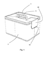
- the Fig. 1 shows a container or bottle crate 2, which is closable with a cover 4.
- the bottle crate 2 can via a carrying handle 6, which is integrated in the lid 4 and with the bottle crate 2 in the in the Fig. 1 shown state, are worn.
- the carrying handle 6 is located centrally and preferably above the center of gravity of the closed bottle crate 2 in the empty state, so that when gripping the carrying handle 6, the bottle crate 2 remains in equilibrium.
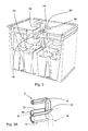
- Fig. 2 shows a perspective cross-sectional view of the bottle crate 2 and the lid 4, wherein in the in the Fig. 2 shown position of the handle 6 is folded and decoupled from the bottle crate 2.
- the Fig. 2 shows thus the state before locking or after unlocking the lid 4, so that the lid 4 can be set in this state on the bottle crate 2 and removed from it.
- the carrying handle 6 has a U-shaped handle portion 8 and a coupling portion 10 which connects the two ends of the handle portion 8 with each other on.
- the carrying handle 6 is pivotally mounted in the lid 4. It jump on both sides of the handle 6 bearing pin 12 (see Fig. 3A ), which engage in corresponding recesses 14 in the lid and are slidably mounted therein.
- the pivot axis A extends between the grip portion 8 and the coupling portion 10, so that the grip portion 8 and coupling portion 10 upon pivoting in the locked state (see Fig. 3 ) project over a top or bottom of the lid 4.
- the coupling portion 10 is half-shell-shaped, so that this when pivoting in the coupled state ( Fig. 3 ) can embrace a centrally or below the handle 6 provided center handle 16 positively.
- the center handle 16 is also U-shaped and has a horizontal or parallel to the lid 4 extending handle portion 18 which can be encompassed by the coupling portion 10 of the handle 6 over its entire length or only partially.
- the coupling portion 10 may be complementary to the handle 18 of the bottle crate 2 or have only functional portions which allow a coupling between the handle 6 of the lid 4 and the center handle 16 of the bottle crate 2.
- the coupling portion 10 may be dimensioned with respect to the handle portion of the bottle crate 2 so that both form a snap connection with each other, so that the carrying handle 6 and the center handle 16 are not only positively connected to each other in the vertical direction, but also form-fitting or frictionally engaged with each other in the pivoting direction are connected, so that a certain force must be applied to the two parts to solve again or unlock the lid 4.
- the cover 4 has two recesses 20, 22 both on its upper side and on its underside, in order to permit the pivoting movement of the carrying handle 6 and, on the other hand, the grip section 8 in the upper recess 20 and the coupling section 10 in FIG bottom recess 22 flush (see Fig. 2 ), so that several decoupled lid can be stacked to save space.
- the carrying handle 6 can thus be pivoted so that it can be completely stowed in the lid 4.
- the carrying handle 6 can be, as from the FIGS. 2 and 3 can be seen, to pivot about 90 °, wherein the pivoting range by a central handle 16 in the coupled position ( Fig. 3 ) or on the other by bottom portions 24, 26 of the recesses 20, 22, with which the grip portion 8 and the coupling portion 10 come into contact, in the decoupled position ( Fig. 2 ) is limited.
- the cover 4 is double-walled, so that the just mentioned bottom sections 24, 26 of the recesses 20, 22 are formed by upper and lower cover walls 28, 30, respectively.
- Fig. 3 shows a passage between the coupling portion 10 and the upper cover wall 28 seals, at least in the coupled state.
- the decoupled state Fig. 2
- the rear side of the half-shell-shaped coupling section 10 comes into abutment with the upper cover wall 28, so that the passage is also closed over it.
- the lower recess 22 in the lower lid wall 30 may be so closely tolerated that a gap between the lower lid wall 30 and the handle portion 18 is minimal and no substantial heat exchange can take place via this gap. Further, the edge of the lower lid wall 30 may be provided with a sealing lip to completely close this gap.
- the Fig. 4 shows a perspective cross-sectional view of the bottle crate 2 with the lid 4 in the coupled and thus locked state.
- a bottom 36 of the bottle crate 2 has a recess 38 which is located immediately below the center handle 16, wherein the handle portion. 8 of the stacked bottle crate 2 finds space.
- the bottle crate 2 according to the invention allows both the stacking of boxes in the unlocked state, because then the carrying handle 6 can be completely stowed in the lid 4, as well as in the locked state, since corresponding recesses 38 are provided on the respective crates 2.
- the Fig. 5 shows the lid 4 without the bottle case 2, wherein the carrying handle 6 is in its vertical position (coupling position).
- the cover 4 can also carry and handle without bottle crate by means of the carrying handle 6.
- the cover 4 on two opposite sides, in the present case on the transverse sides, covering 40 has to lateral handle openings 42 (see FIGS. 1 and 7 ) to close with it.
- the cover elements 40 are pivotally mounted on an edge portion of the lid 4 and can from the in the Fig. 5 shown position can be pivoted by about 270 ° upwards and find place in appropriately trained recesses 44, wherein the cover find flush and do not protrude beyond the top cover wall 28.
- the Fig. 6 shows the lid 4 in a perspective bottom view with the centrally projecting coupling portion 10 and the two cover members 40.
- the cover 40 on the inside, ie the bottle crate 2 out, projections 45 which are formed according to the shape of the lateral handle openings 42, engage therein and there are frictionally or positively fixed.
- four rectangular and axially symmetrical receptacles 46 are located on the lower lid wall 30, in each of which a cooling battery 48 are received positively or frictionally.
- the cooling batteries 48 can be removed to be placed in a refrigerator or freezer and then used to cool the goods contained in the container or bottle crate, as well as from the FIGS. 7 and 8 is apparent.
- the lid 4 is double-walled, located between the receptacle 46 and the upper cover wall 28 air, so that the heat conduction to the outside is very low and the cooling batteries can keep their temperature long.
- FIGS. 7 and 8 From the FIGS. 7 and 8 can also be seen how the sealing lips 32 and 34, the air exchange between the bottle crate 2 and the outside is prevented. Further, the bottom 36 and side walls 50 of the bottle crate 2 can be additionally provided with an insulating layer.
- the invention is not limited to a bottle crate, but can be applied to all containers to be carried by hand.
- the center handle of the bottle crate acts as an anchor point in the context of the invention, with which the carrying handle of the lid is coupled.
- cover elements for closing side handle openings can be dispensed with if the container to be closed has no such. It can be completely dispensed with the lid on any insulation and cooling functionality (shots for the cooling batteries, sealing lips on the handle, Doppelwandtechnik the lid, etc.), if the lid is only intended to serve as a closure. So z.
- the carrying handle can also be stored differently in the lid.
- the lid may be rotatable about an axis perpendicular to the lid plane formed and coupled via the rotational movement with the arranged in the bottle crate center handle.
- the handle portion could be formed pivotable with respect to the coupling portion alone to accommodate it in a corresponding recess on the lid top, when the carrying handle is not needed, while the coupling portion remains in its vertical, coupled position.
- the invention is also applicable to divisible bottle crates.
- a half bottle case with a center handle is to be understood as a bottle crate in the context of the invention.
Landscapes
- Engineering & Computer Science (AREA)
- Mechanical Engineering (AREA)
- Ceramic Engineering (AREA)
- Details Of Rigid Or Semi-Rigid Containers (AREA)
- Closures For Containers (AREA)
Description
- Die vorliegende Erfindung betrifft einen Deckel für einen Behälter, insbesondere einen Flaschenkasten, gemäß dem Oberbegriff des Anspruchs 1 sowie einen verschließbaren Behälter.
- Aus dem Stand der Technik sind unterschiedlichste Deckel-Behälter-Anordnungen für diverse Anwendungen bekannt. Ein Teil dieser Behälter weist Verschlusssysteme auf, um den Deckel gegen unbeabsichtigtes Lösen zu sichern. In vielen Fällen befinden sich Verriegelungsorgane an den Außenseiten des Behälters, mit welchen Randabschnitte des Deckels gegen den Behälter geklemmt werden (siehe z. B.
US 4 691 840 A ,US 4 819 827 A ,DE 197 29 265 A1 ,US 2010/0084403 A1 ) oder umgekehrt (siehe z.B.CA 2 580 155 A1 ). - Bei tragbaren Behältern sind Tragegriffe entweder am Behälter oder am Deckel vorgesehen. Wenn der Handgriff am Behälter vorgesehen ist, hat dies den Nachteil, dass der Griff außerhalb der Schwerpunktebene liegt und beim einhändigen Tragen der Behälter kippt. Befindet sich der Tragegriff mittig am Deckel, wie z. B. in
CA 2 580 155 A1 ,US 4 225 052 A oderEP 2 078 681 A1 gezeigt ist, verbessert dies zwar den Tragekomfort, jedoch muss hier der Deckel über die Verriegelungsorgane und Randabschnitte das Gewicht des gesamten Behälters aufnehmen, so dass diese Variante bei schwerer beladenen Behältern, z. B. Flaschenkästen, nur bedingt einsetzbar ist. - Bei Flaschenkästen ist man unter Berücksichtigung des Tragekomforts dazu übergegangen, mittig im Flaschenkasten zusätzlich einen Mittelhandgriff vorzusehen. Deckelanordnungen für Flaschenkästen mit Mittelhandgriff sind z. B. aus
FR 2 648 439 A1 DE 1 009 580 A3 bekannt. Hierbei lassen sich die mit dem Deckel verschlossenen Flaschenkästen über einen teleskopartig ausfahrbaren Mittelhandgriff des Flaschenkastens tragen. Jedoch sind bei diesen Anordnungen die Deckel gar nicht oder nur unzureichend am Flaschenkasten befestigt. - Aufgabe der vorliegenden Erfindung ist es deshalb, einen Deckel für einen Behälter sowie einen verschließbaren Behälter mit einem solchen Deckel bereitzustellen, die die oben genannten Nachteile überwinden, insbesondere einen sicheren Verschluss von selbst schwer beladenen Behältern bei gleichzeitig hohem Tragekomfort realisieren.
- Die Aufgabe wird hinsichtlich des Deckels durch die Merkmale des Anspruchs 1 gelöst.
- Erfindungsgemäß ist im Deckel ein Tragegriff integriert, durch dessen Lageveränderung der Deckel gegen Lösen vom Behälter gesichert werden kann. Dabei ist der zentral im Deckel angeordnete Tragegriff unmittelbar mit einem zentral im Behälter angeordneten Ankerpunkt in Gestalt des Mittelhandgriffs koppelbar.
- Aufgrund der direkten Kopplung von Tragegriff und einem Ankerpunkt (Zugpunkt oder Lastangriffspunkt) im Behälter ist der Deckel beim Tragen des Behälters im Wesentlichen lastfrei. Durch die unmittelbare Kopplung von Tragegriff und Behälter kann der Tragegriff, obwohl er in dem Deckel integriert ist, als Teil des Behälters gesehen werden. Andererseits ist der Deckel im gekoppelten Zustand gegen Lösen vom Behälter gesichert, da der mit dem Behälter verbundene Tragegriff ferner mit dem Deckel gekoppelt ist.
- Der erfindungsgemäße Deckel hat ferner den Vorteil, dass er wegen seiner zentralen Anordnung im Deckel einen hohen Tragekomfort beim einhändigen Tragen bietet, da der Behälter sich im Gleichgewicht befindet.
- Ferner erfüllt der Tragegriff gleich zwei Funktionen, nämlich die Tragefunktion und zugleich die Verschlussfunktion, so dass der Deckel bzw. der Behälter ohne weitere zusätzliche Verriegelungsorgane auskommt, was sich vorteilhaft bei der Herstellung beider Teile und somit auch bei den Kosten herausstellt.
- Ein wesentlicher weiterer Vorteil kann darin gesehen werden, dass der stets lastfreie Deckel schlanker ausgelegt werden kann, was zu weiteren Einsparungen beim Material und Gewicht führt. Da insbesondere die Randabschnitte keine Klemmkräfte von Verriegelungsorganen aufnehmen müssen und auch nicht die gesamte Last des Behälters tragen müssen, können diese im Hinblick auf andere Anforderungen, wie z.B. Abdichtung, optimiert werden.
- Wenn vorzugsweise der Ankerpunkt mit dem Behälterboden verbunden ist, sind auch die Seitenwände des Behälters im Wesentlichen lastfrei und können diese ebenfalls entsprechend, z.B. in Hinblick auf Design, optimiert werden.
- Die oben genannten Vorteile machen sich bei einem Flaschenkasten mit einem Mittelhandgriff bezahlt. Dann kann der zur Handhabung des Flaschenkastens ohnehin vorgesehene Mittelhandgriff auch als Ankerpunkt für den Tragegriff im Deckel fungieren. Wenn der Tragegriff mit dem Mittelhandgriff gekoppelt ist, stellt der Tragegriff im Wesentlichen eine Verlängerung des Mittelhandgriffs im Flaschenkasten dar. Somit kann man auf komplizierte und auch anfällige Teleskophandgriffe, wie sie in dem oben genannten Stand der Technik gezeigt sind, verzichten.
- Da mittlerweile sehr viele Flaschenkästen mit Mittelhandgriffen versehen sind, kann der erfindungsgemäße Deckel als eine Art Zubehör für gewöhnliche Flaschenkästen angesehen werden. Dies hat wiederum den Vorteil, dass der gleiche Kasten mit und ohne Deckel verwendet und somit verkauft werden kann, und keine spezielle Flaschenkastenvariante entwickelt werden muss. Ferner besteht dadurch die Möglichkeit, dass vorhandene Flaschenkästen zu einem späteren Zeitpunkt mit einem erfindungsgemäßen Deckel nachgerüstet werden können.
- Vorzugsweise ist der Tragegriff im Deckel um eine senkrecht zur Deckelebene verlaufende Achse drehbar gelagert und lässt sich zwischen zwei Lagen bezüglich des Deckels bzw. des Behälters drehen, wobei der Tragegriff in der einen Lage mit dem Ankerpunkt gekoppelt ist und in der anderen Lage vom Ankerpunkt entkoppelt ist. Hierbei lässt sich durch eine einfach realisierbare mechanische Bewegung der Tragegriff mit dem Ankerpunkt des Behälters koppeln und entkoppeln.
- Bei einem zylindrischen Behälter ist das Koppeln und Entkoppeln von Tragegriff und Ankerpunkt noch einfacher zu realisieren, da hier keine Relativbewegung zwischen Tragegriff und Deckel notwendig ist und der Deckel mitsamt dem Tragegriff zwischen den beiden Lagen relativ zum Behälter verdreht werden kann.
- Alternativ ist der Tragegriff im Deckel um eine im Wesentlichen in der Deckelebene liegende Achse schwenkbar gelagert und kann zwischen einer ersten und einer zweiten Lage bezüglich des Deckels geschwenkt werden, so dass der Tragegriff in der einen Lage mit dem Ankerpunkt gekoppelt ist und in der anderen Lage vom Ankerpunkt entkoppelt ist. Diese Variante lässt sich noch einfacher realisieren, z. B. indem Lagerzapfen in entsprechenden Ausnehmungen im Deckel drehbar aufgenommen sind.
- Ein weiterer Vorteil der Schwenkvariante liegt darin, dass der Tragegriff bei entsprechend vorgesehenen Ausnehmungen im Deckel so verschwenkt werden kann, dass der Tragegriff im entkoppelten und damit vom Behälter lösbaren Zustand vollständig im Deckel aufgenommen werden kann, so dass mehrere Deckel übereinander platzsparend gestapelt werden können und die Tragegriffe dies zulassen.
- Vorzugsweise weist der Tragegriff dabei einen Griffabschnitt und einen Kopplungsabschnitt auf und ist zwischen dem Griffabschnitt und dem Kopplungsabschnitt im Deckel gelagert. In der ersten Lage (im gekoppelten Zustand) springen der Griffabschnitt und der Kopplungsabschnitt über eine obere Deckelfläche bzw. eine untere Deckelfläche vor, wohingegen sie in der zweiten Lage (im entkoppelten Zustand) so weit verschwenkbar sind, dass Griffabschnitt und/oder der Kopplungsabschnitt vollständig in einer Ausnehmung auf der oberen Seite bzw. auf der unteren Seite des Deckels aufgenommen sind. Dadurch wird der oben erwähnte Vorteil erreicht.
- Wenn es sich bei dem Behälter um einen Flaschenkasten handelt, kann der Kopplungsabschnitt komplementär zum Mittelhandgriff und insbesondere halbschalenförmig ausgebildet sein, um den Mittelhandgriff formschlüssig umgreifen zu können. Auch wenn ein Umgreifen des Mittelhandgriffs an sich für die Tragefunktion ausreichend ist, so ist es umso vorteilhafter, wenn Kopplungsabschnitt und Mittelhandgriff so zueinander ausgebildet sind, dass sie eine Art Schnappverbindung eingehen, wodurch sichergestellt wird, dass der Tragegriff nicht versehentlich vom Mittelhandgriff entkoppelt wird und sich beim Anheben des Handgriffs der Deckel löst. Der Vorteil dieses Formschlusses zwischen Tragegriff und Mittelhandgriff ermöglicht ein sehr einfaches Verschließen und Lösen des Deckels und erfordert darüber hinaus keine zusätzlichen Befestigungsvorrichtungen oder Handhabungsschritte. Der Verschluss kommt somit ohne zusätzliche komplexe mechanische Teile, wie sie zum Teil im oben genannten Stand der Technik Anwendung finden, aus.
- Da zum Verschließen und Lösen des Deckels am Behälter die Lage des Tragegriffs verändert werden muss, sei es durch Drehung, Schwenken oder anderweitig, können die damit verbundenen Durchtritte im Deckel über zumindest eine am Tragegriff vorgesehene Dichtlippe oder Dichtblende geschlossen oder zumindest minimiert werden. Damit wird sichergestellt, dass keine Fremdpartikel in den Behälter gelangen bzw. nichts aus dem Behälter austritt. Insbesondere, wenn der erfindungsgemäße Deckel einen Isolierbehälter verschließen soll, verhindert die Dichtlippe darüber hinaus einen Wärmeaustausch zwischen dem Behälterinneren und der Umwelt.
- Im konkreten Fall eines isolierbaren Flaschenkastens kann der Tragegriff zwei Dichtlippen aufweisen, von denen die eine in Kontakt mit dem Mittelhandgriff des Flaschenkastens ist und die anderen in Kontakt mit einer Deckelwandung ist. Darüber hinaus kann der Deckel an seiner Unterseite ebenfalls eine Dichtlippe aufweisen, die, wenn sich der Deckel auf dem Flaschenkasten befindet, in Kontakt mit dem Mittelhandgriff des Flaschenkastens ist. Dadurch lassen sich die im Flaschenkasten mitgeführten Getränke trotz der Tragegriffmimik kalt oder warm halten.
- Ferner kann der Deckel an seiner Unterseite zumindest eine Ausnehmung zur lösbaren, formschlüssigen Aufnahme eines Kühlakkus aufweisen. Die Unterseite des Deckels ist dem Behälterinneren zugewandt, wodurch die Wärme- bzw. Kältestrahlung des Kühlakkus die im Behälter befindliche Ware kühl halten kann.
- Um die Isolierwirkung des Deckels weiter zu erhöhen, kann der Deckel doppelwandig mit einer oberen Deckelwandung und einer unteren Deckelwandung und dazwischen Luft, Vakuum, Isoliermaterial, etc. aufweisen. Dadurch wird noch weniger Wärme über den Deckel abgegeben.
- Da Flaschenkästen neben mit dem Mittelhandgriff meist seitliche Handgriffsöffnungen aufweisen, ist es vorteilhaft, wenn am Deckel entsprechende Abdeckelemente vorgesehen sind, die sich schwenken lassen und die seitlichen Handgriffsöffnungen verschließen können. Dadurch lässt sich ein gewöhnlicher Flaschenkasten mittels des erfindungsgemäßen Deckels nachträglich zu einem geschlossenen und isolierten Flaschenkasten umfunktionieren.
- Vorzugsweise lässt sich das Abdeckelement in einer ersten, vorzugsweise arretierbaren Schwenkstellung in einer entsprechend vorgesehenen Vertiefung an der Deckeloberseite bündig aufnehmen und ist in der zweiten Schwenkstellung, d.h. Abdeckstellung, mit der seitlichen Handgriffsöffnung, vorzugsweise über einen Vorsprungsabschnitt, in Wirkverbindung. Dies hat den Vorteil, dass die Abdeckelemente platzsparend im Deckel untergebracht sind und sich mehrere Deckel trotz der vorgesehenen Abdeckelemente übereinander stapeln lassen. Andererseits lassen sich die Abdeckelemente, wenn sie die Handgriffsöffnung abdecken, mit dem Behälter sicher und lösbar koppeln.
- Die Aufgabe der Erfindung hinsichtlich des verschließbaren Behälters wird durch die Merkmale des Anspruchs 9 gelöst.
- Bei dem erfindungsgemäßen Behälter handelt es sich um einen verschließbaren Behälter mit einem zentral angeordneten Mittelhandgriff und einem Deckel nach der oben beschriebenen Art.
- Vorzugsweise weist der Behälter am Boden eine Vertiefung auf, um einen Tragegriff eines anderen Behälters aufzunehmen, wenn mehrere baugleiche Behälter aufeinander gestapelt sind. Wie oben bereits erwähnt, springt der Tragegriff über die obere Deckelfläche vor, wenn sich der Tragegriff im gekoppelten Zustand mit dem Behälter befindet. Eine entsprechende Vertiefung im Boden der Behälter ermöglicht somit das Aufeinanderstapeln mehrerer Behälter im gekoppelten Zustand, d.h. mit sicher verschlossenem Deckel.
- Vorzugsweise ist der verschließbare Behälter als Isolierbehälter ausgebildet und der Boden und/oder die Seitenwandung weisen eine oder mehrere Isolierschichten auf.
- Die vorliegende Erfindung wird anhand der beigefügten Zeichnungen näher dargestellt. Es zeigen:
-
Fig. 1 einen verschließbaren Flaschenkasten gemäß einer bevorzugten Ausführungsform der Erfindung; -
Fig. 2 eine perspektivische Querschnittsansicht des Flaschenkastens mit einem Deckel im unverriegelten Zustand; -
Fig. 3 eine perspektivische Querschnittsansicht des Flaschenkastens mit einem Deckel im verriegelten Zustand; -
Fig. 3A eine perspektivische Querschnittsansicht lediglich eines Tragegriffs gemäß der bevorzugten Ausführungsform der Erfindung; -
Fig. 4 eine perspektivische Querschnittsansicht des Flaschenkastens von oben; -
Fig. 5 eine perspektivische Draufsicht des Deckels gemäß der bevorzugten Ausführungsform; -
Fig. 6 eine perspektivische Unteransicht des Deckels; -
Fig. 7 eine perspektivische Querschnittsansicht des Flaschenkastens von unten im unverriegelten Zustand; und -
Fig. 8 eine perspektivische Querschnittsansicht des Flaschenkastens von unten im verriegelten Zustand. - Die
Fig. 1 zeigt einen Behälter bzw. Flaschenkasten 2, der mit einem Deckel 4 verschließbar ist. Der Flaschenkasten 2 kann über einen Tragegriff 6, der im Deckel 4 integriert ist und mit dem Flaschenkasten 2 in dem in derFig. 1 gezeigten Zustand gekoppelt ist, getragen werden. Der Tragegriff 6 befindet sich mittig und vorzugsweise oberhalb des Gesamtschwerpunkts des verschlossenen Flaschenkastens 2 im leeren Zustand, so dass beim Greifen des Tragegriffs 6 der Flaschenkasten 2 im Gleichgewicht bleibt. -
Fig. 2 zeigt eine perspektivische Querschnittsansicht des Flaschenkastens 2 und des Deckels 4, wobei in der in derFig. 2 gezeigten Stellung der Tragegriff 6 umgelegt ist und vom Flaschenkasten 2 entkoppelt ist. DieFig. 2 zeigt somit den Zustand vor dem Verriegeln bzw. nach dem Entriegeln des Deckels 4, so dass der Deckel 4 in diesem Zustand auf den Flaschenkasten 2 gesetzt bzw. von diesem entfernt werden kann. - Der Tragegriff 6 weist einen U-förmig ausgebildeten Griffabschnitt 8 und einen Kopplungsabschnitt 10, der die beiden Enden des Griffabschnitts 8 miteinander verbindet, auf. Der Tragegriff 6 ist schwenkbar in dem Deckel 4 gelagert. Dabei springen zu beiden Seiten des Tragegriffs 6 Lagerzapfen 12 (siehe
Fig. 3A ) vor, die in entsprechende Ausnehmungen 14 im Deckel eingreifen und darin gleitend gelagert sind. Die Schwenkachse A verläuft zwischen dem Griffabschnitt 8 und dem Kopplungsabschnitt 10, so dass der Griffabschnitt 8 und Kopplungsabschnitt 10 beim Verschwenken in den gekoppelten bzw. verriegelten Zustand (sieheFig. 3 ) über eine Oberseite bzw. Unterseite des Deckels 4 vorspringen. - Wie aus der
Fig. 2 ferner zu erkennen ist, ist der Kopplungsabschnitt 10 halbschalenförmig ausgebildet, so dass dieser beim Verschwenken in den gekoppelten Zustand (Fig. 3 ) einen mittig bzw. unterhalb des Tragegriffs 6 vorgesehenen Mittelhandgriff 16 formschlüssig umgreifen kann. Der Mittelhandgriff 16 ist ebenfalls U-förmig ausgebildet und weist einen horizontal bzw. parallel zum Deckel 4 verlaufenden Griffabschnitt 18 auf, welcher vom Kopplungsabschnitt 10 des Tragegriffs 6 über dessen gesamte Länge oder nur teilweise umgriffen werden kann. - Der Kopplungsabschnitt 10 kann komplementär zu dem Handgriff 18 des Flaschenkastens 2 ausgebildet sein oder lediglich Funktionsabschnitte aufweisen, welche eine Kopplung zwischen dem Tragegriff 6 des Deckels 4 und dem Mittelhandgriff 16 des Flaschenkastens 2 ermöglichen. Der Kopplungsabschnitt 10 kann bezüglich des Griffabschnitts des Flaschenkastens 2 so dimensioniert sein, dass beide eine Art Schnappverbindung miteinander eingehen, so dass der Tragegriff 6 und der Mittelhandgriff 16 nicht nur formschlüssig in vertikaler Richtung miteinander verbunden sind, sondern auch formschlüssig bzw. reibschlüssig in Schwenkrichtung miteinander verbunden sind, so dass eine gewisse Kraft aufgebracht werden muss, um die beiden Teile wieder voneinander zu lösen bzw. den Deckel 4 zu entriegeln.
- Wie aus der
Fig. 3 ferner ersichtlich ist, weist der Deckel 4 sowohl an seiner Oberseite als auch an seiner Unterseite zwei Ausnehmungen 20, 22 auf, um zum einen die Schwenkbewegung des Tragegriffs 6 zuzulassen und um andererseits den Griffabschnitt 8 in der oberen Ausnehmung 20 und den Kopplungsabschnitt 10 in der unteren Ausnehmung 22 bündig aufzunehmen (sieheFig. 2 ), so dass mehrere entkoppelte Deckel platzsparend übereinander gestapelt werden können. Der Tragegriff 6 kann also so verschwenkt werden, dass er vollständig im Deckel 4 verstaut werden kann. Der Tragegriff 6 lässt sich, wie aus denFign. 2 und3 ersichtlich ist, um ca. 90° verschwenken, wobei der Schwenkbereich zum einen durch den Mittelhandgriff 16 in der gekoppelten Stellung (Fig. 3 ) bzw. zum anderen durch Bodenabschnitte 24, 26 der Ausnehmungen 20, 22, mit welchem der Griffabschnitt 8 bzw. der Kopplungsabschnitt 10 in Anlage kommen, im entkoppelten Stellung (Fig. 2 ) begrenzt wird. - Gemäß der vorliegenden Ausführungsform ist der Deckel 4 doppelwandig ausgebildet, so dass die soeben genannten Bodenabschnitte 24, 26 der Ausnehmungen 20, 22 durch eine obere bzw. untere Deckelwandung 28, 30 gebildet werden.
- Wegen der Schwenkmöglichkeit des Tragegriffs 6 im Deckel 4 befindet sich ein Durchtritt zwischen der oberen und unteren Ausnehmung 20, 22. Deshalb sind an dem Tragegriff 6 ferner zwei Dichtlippen 32, 34 vorgesehen, wovon die eine in Kontakt mit dem Griffabschnitt 18 des Mittelhandgriffs 16 steht und die andere, wie insbesondere aus
Fig. 3 hervorgeht, einen Durchtritt zwischen dem Kopplungsabschnitt 10 und der oberen Deckelwandung 28 abdichtet, zumindest im gekoppelten Zustand. Im entkoppelten Zustand (Fig. 2 ) kommt die Rückseite des halbschalenförmigen Kopplungsabschnitts 10 in Anlage mit der oberen Deckelwandung 28, so dass hierüber der Durchtritt ebenfalls verschlossen wird. - Die untere Ausnehmung 22 in der unteren Deckelwandung 30 kann so eng toleriert sein, dass ein Spalt zwischen der unteren Deckelwandung 30 und dem Griffabschnitt 18 minimal ist und kein wesentlicher Wärmeaustausch über diesen Spalt erfolgen kann. Ferner kann die Kante der unteren Deckelwandung 30 mit einer Dichtlippe versehen werden, um diesen Spalt vollständig zu verschließen.
- Die
Fig. 4 zeigt eine perspektivische Querschnittsansicht des Flaschenkastens 2 mit dem Deckel 4 im gekoppelten und damit verriegelten Zustand. Um mehrere solche Flaschenkästen 2 im verriegelten Zustand übereinander stapeln zu können, d.h. mit einem über die obere Deckelwandung 28 vorspringenden Griffabschnitt 8, weist ein Boden 36 des Flaschenkastens 2 eine Ausnehmung 38 auf, die sich unmittelbar unterhalb des Mittelhandgriffs 16 befindet, worin der Griffabschnitt 8 des darunter gestapelten Flaschenkastens 2 Platz findet. Somit erlaubt der erfindungsgemäße Flaschenkasten 2 sowohl das Stapeln von Kästen im entriegelten Zustand, weil dann der Tragegriff 6 vollständig im Deckel 4 verstaut werden kann, als auch im verriegelten Zustand, da entsprechende Ausnehmungen 38 an den jeweiligen Flaschenkästen 2 vorgesehen sind. - Die
Fig. 5 zeigt den Deckel 4 ohne den Flaschenkasten 2, wobei sich der Tragegriff 6 in seiner vertikalen Position (Kopplungslage) befindet. Somit lässt sich der Deckel 4 auch ohne Flaschenkasten mittels des Tragegriffs 6 tragen und handhaben. Aus derFig. 5 ist ferner erkennbar, dass der Deckel 4 an zwei gegenüberliegenden Seiten, im vorliegenden Fall an den Querseiten, Abdeckelemente 40 aufweist, um seitliche Handgriffsöffnungen 42 (sieheFign. 1 und7 ) damit zu verschließen. Die Abdeckelemente 40 sind an einem Kantenabschnitt des Deckels 4 schwenkbar gelagert und können von der in derFig. 5 gezeigten Stellung um ca. 270° nach oben geschwenkt werden und finden Platz in entsprechend ausgebildeten Ausnehmungen 44, worin die Abdeckelemente bündig Platz finden und nicht über die obere Deckelwandung 28 vorstehen. - Die
Fig. 6 zeigt den Deckel 4 in einer perspektivischen Unteransicht mit dem mittig vorspringenden Kopplungsabschnitt 10 sowie den beiden Abdeckelementen 40. Wie aus derFig. 6 zu erkennen ist, weisen die Abdeckelemente 40 innenseitig, d.h. zum Flaschenkasten 2 hin, Vorsprünge 45 auf, die entsprechend der Form der seitlichen Handgriffsöffnungen 42 ausgebildet sind, darin eingreifen und dort reibschlüssig oder formschlüssig fixierbar sind. Ferner befinden sich an der unteren Deckelwandung 30 vier rechteckige und achsensymmetrisch angeordnete Aufnahmen 46, in denen jeweils ein Kühlakku 48 form- oder reibschlüssig aufgenommen sind. Die Kühlakkus 48 lassen sich herausnehmen, um in ein Kühl- oder Gefrierfach gelegt und anschließend zum Kühlen der im Behälter bzw. Flaschenkasten befindlichen Ware eingesetzt werden zu können, wie auch aus denFign. 7 und 8 ersichtlich ist. - Da, wie aus den
Fign. 7 und 8 zu sehen ist und wie bereits oben erwähnt, der Deckel 4 doppelwandig ausgebildet ist, befindet sich zwischen der Aufnahme 46 und der oberen Deckelwandung 28 Luft, so dass die Wärmeleitung nach außen sehr gering ist und die Kühlakkus ihre Temperatur lange halten können. - Aus den
Fign. 7 und 8 ist auch zu erkennen, wie über die Dichtlippen 32 und 34 der Luftaustausch zwischen Flaschenkasten 2 und Außen unterbunden wird. Ferner können der Boden 36 und Seitenwände 50 des Flaschenkastens 2 zusätzlich mit einer Isolierschicht versehen werden. - Ferner kann zur weiteren Abdichtung zwischen einem umlaufenden Schulterabschnitt 52 (siehe
Fig. 6 ) und auf einem oberen Rand 54 der Seitenwände 50, auf welchem der Deckel 4 aufliegt eine Dichtung eingebracht werden. Da der Tragegriff 6 über die Lagerzapfen 12 im Deckel 4 gelagert ist, wird der Deckel, wenn der Tragegriff 6 mit dem Mittelhandgriff 16 gekoppelt wird, am oberen Randabschnitt 54 der Seitenwände 50 gehalten. Bei entsprechender Tolerierung des Zusammenspiels von Tragegriff 6 und Mittelhandgriff 16 wird der Deckel 4 entsprechend gegen den oberen Randabschnitt 54 gespannt, wohingegen beim Stand der Technik bislang der Randabschnitt beim Anheben des Deckels eher von dem Randabschnitt der Seitenwandung abgehoben wurde. - Die vorliegende Erfindung wurde anhand einer bevorzugten Ausführungsform beschrieben. Selbstverständlich ist der Schutzbereich durch die Ansprüche definiert.
- Zum Beispiel ist die Erfindung nicht auf einen Flaschenkasten beschränkt, sondern kann auf sämtliche von Hand zu tragende Behälter übernommen werden.
- Bei der Erfindung fungiert der Mittelhandgriff des Flaschenkastens als Ankerpunkt im Sinne der Erfindung, mit welchem der Tragegriff des Deckels gekoppelt wird.
- Ferner kann auf die Abdeckelemente zum Verschließen von seitlichen Handgriffsöffnungen verzichtet werden, wenn der zu verschließende Behälter keine solchen aufweist. Es kann bei dem Deckel auch komplett auf jegliche Isolier- und Kühlfunktionalität (Aufnahmen für die Kühlakkus, Dichtlippen am Tragegriff, Doppelwandigkeit des Deckels, etc.) verzichtet werden, wenn der Deckel lediglich als Verschluss dienen soll. So kann z. B. der Getränkehersteller bei der Auslieferung den Getränkekasten über den erfindungsgemäßen Deckel verschließen und gegebenenfalls verplomben, so dass sichergestellt wird, dass keine Inhalte vertauscht oder entnommen werden.
- Anstatt den Tragegriff - wie beschrieben - um eine Achse in der Deckelebene zu schwenken, kann der Tragegriff auch anders im Deckel gelagert sein. Zum Beispiel kann der Deckel um eine zur Deckelebene senkrecht ausgebildete Achse drehbar sein und über die Drehbewegung mit dem im Flaschenkasten angeordneten Mittelhandgriff gekoppelt werden. Dabei könnte der Griffabschnitt bezüglich des Kopplungsabschnitts alleine schwenkbar ausgebildet sein, um ihn in eine entsprechende Ausnehmung an der Deckeloberseite unterzubringen, wenn der Tragegriff nicht benötigt wird, während der Kopplungsabschnitt in seiner vertikalen, gekoppelten Stellung verbleibt.
- Die Erfindung ist auch auf teilbare Flaschenkästen anwendbar. Somit ist auch ein halber Flaschenkasten mit einem Mittelhandgriff als ein Flaschenkasten im Sinne der Erfindung zu verstehen.
-
2 Flaschenkasten 4 Deckel 6 Tragegriff 8 Griffabschnitt 10 Kopplungsabschnitt 12 Lagerzapfen 14 Ausnehmung 16 Mittelhandgriff 18 Griffabschnitt 20 obere Ausnehmung 22 untere Ausnehmung 24 Bodenabschnitt 26 Bodenabschnitt 28 obere Deckelwandung 30 untere Deckelwandung 32 Dichtlippe 34 Dichtlippe 36 Boden 38 Ausnehmung 40 Abdeckelement 42 Handgriffsöffnung 44 Ausnehmung 45 Vorsprung 46 Aufnahme 48 Kühlakku 50 Seitenwand 52 Schulterabschnitt 54 Randabschnitt A Schwenkachse
Claims (10)
- Deckel (4) für einen Behälter (2), insbesondere einen Flaschenkasten, mit einem im Deckel (4) integrierten und lageveränderlichen Tragegriff (6), wobei der Deckel (4) durch Lageveränderung des Tragegriffs (6) gegen Lösen vom Behälter (2) gesichert werden kann, dadurch gekennzeichnet, dass
der zentral im Deckel (4) angeordnete Tragegriff (6) unmittelbar mit einem zentral im Behälter (2) angeordneten, insbesondere mit einem Behälterboden (36) verbundenen, Mittelhandgriff (16) koppelbar ist. - Deckel (4) nach Anspruch 1, dadurch gekennzeichnet, dass
der Tragegriff (6) im Deckel (4) um eine im Wesentlichen in der Deckelebene oder parallel zur dieser liegende Achse (A) schwenkbar gelagert ist und zumindest zwischen einer ersten und einer zweiten Lage bezüglich des Deckels (4) schwenkbar ist, wobei der Tragegriff (6) in der ersten Lage mit dem Mittelhandgriff (16) gekoppelt ist und in der zweiten Lage vom Mittelhandgriff (16) entkoppelt ist. - Deckel (4) nach Anspruch 1 oder 2, dadurch gekennzeichnet, dass
der Tragegriff (6) einen Griffabschnitt (8) und einen Kopplungsabschnitt (10) aufweist und zwischen dem Griffabschnitt (8) und dem Kopplungsabschnitt (10) im Deckel (4) gelagert ist, wobei in der ersten Lage der Griffabschnitt (8) und der Kopplungsabschnitt (10) über eine obere bzw. untere Seite vorspringen und in der zweiten Lage der Griffabschnitt (8) und/oder der Kopplungsabschnitt (10) vollständig im Deckel (4), insbesondere in einer entsprechenden Ausnehmung (20, 22) an einer oberen bzw. unteren Seite des Deckels (4), aufgenommen ist. - Deckel (4) nach Anspruch 3, dadurch gekennzeichnet, dass
der Kopplungsabschnitt (10) zum formschlüssigen Umgreifen des Mittelhandgriffs (16) im Wesentlichen komplementär zu dem Mittelhandgriff (16), insbesondere halbschalenförmig, ausgebildet ist. - Deckel (4) nach einem der Ansprüche 1 bis 4, dadurch gekennzeichnet, dass ein durch die Lageveränderung des Tragegriffs (6) bedingter Durchtritt im Deckel (4) über zumindest eine am Tragegriff (6) vorgesehene Dichtlippe (32, 34) geschlossen oder zumindest minimiert wird.
- Deckel (4) nach einem der Ansprüche 1 bis 5, dadurch gekennzeichnet, dass
der Deckel (4) auf der dem Behälter (2) zugewandten, unteren Seite zumindest eine Ausnehmung (46) zur lösbaren, formschlüssigen Aufnahme eines Kühlakkus (48) aufweist. - Deckel (4) nach einem der Ansprüche 1 bis 6, dadurch gekennzeichnet, dass
am Deckel (4), vorzugsweise an einem Randabschnitt des Deckels (4), zumindest ein Abdeckelement (40) zum Abdecken einer seitlichen Handgriffsöffnung (42) des Behälters (2) schwenkbar gelagert ist. - Deckel (4) nach Anspruch 7, dadurch gekennzeichnet, dass
das Abdeckelement (40) in einer ersten, vorzugsweise arretierbaren, Schwenkstellung in einer Vertiefung an einer Oberseite des Deckels (4) bündig aufgenommen ist und in einer zweiten, vorzugsweise arretierbaren, Schwenkstellung die seitliche Handgriffsöffnung (42) abdeckt. - Verschließbarer Behälter (2), insbesondere Flaschenkasten, mit einem zentral angeordneten, insbesondere mit dem Behälterboden (36) verbundenen, Mittelhandgriff (16) und einem Deckel (4) nach einem der Ansprüche 1 bis 8.
- Verschließbarer Behälter (2) nach Anspruch 9, dadurch gekennzeichnet, dass
der Behälter (2) am Boden (36) eine Vertiefung (38) zur Aufnahme eines Tragegriffs (6) eines baugleichen Behälters (2), wenn dieser auf dem baugleichen Behälter (2) gestapelt ist.
Applications Claiming Priority (2)
| Application Number | Priority Date | Filing Date | Title |
|---|---|---|---|
| DE102011000598A DE102011000598B3 (de) | 2011-02-09 | 2011-02-09 | Mit einem Deckel verschließbarer Behälter |
| PCT/EP2011/071638 WO2012107125A1 (de) | 2011-02-09 | 2011-12-02 | MIT EINEM DECKEL VERSCHLIEßBARER FLASCHENKASTEN |
Publications (2)
| Publication Number | Publication Date |
|---|---|
| EP2507137A1 EP2507137A1 (de) | 2012-10-10 |
| EP2507137B1 true EP2507137B1 (de) | 2013-05-01 |
Family
ID=45063178
Family Applications (1)
| Application Number | Title | Priority Date | Filing Date |
|---|---|---|---|
| EP11788900.6A Not-in-force EP2507137B1 (de) | 2011-02-09 | 2011-12-02 | Mit einem deckel verschliessbarer flaschenkasten |
Country Status (4)
| Country | Link |
|---|---|
| EP (1) | EP2507137B1 (de) |
| CA (1) | CA2775207A1 (de) |
| DE (1) | DE102011000598B3 (de) |
| WO (1) | WO2012107125A1 (de) |
Families Citing this family (6)
| Publication number | Priority date | Publication date | Assignee | Title |
|---|---|---|---|---|
| DE102012016163A1 (de) * | 2012-08-14 | 2014-02-20 | Schoeller Arca Systems Gmbh | Behälter mit Eingriffsschutz, insbesondere Postbehälter |
| USD1024557S1 (en) | 2022-06-08 | 2024-04-30 | Yeti Coolers, Llc | Container |
| USD1063376S1 (en) | 2022-06-08 | 2025-02-25 | Yeti Coolers, Llc | Container |
| US11912477B2 (en) | 2022-06-08 | 2024-02-27 | Yeti Coolers, Llc | Container with handle and latching system |
| USD1036116S1 (en) | 2022-06-08 | 2024-07-23 | Yeti Coolers, Llc | Container |
| USD1036119S1 (en) | 2022-11-30 | 2024-07-23 | Yeti Coolers, Llc | Container |
Family Cites Families (13)
| Publication number | Priority date | Publication date | Assignee | Title |
|---|---|---|---|---|
| DE1009580B (de) | 1942-12-05 | 1957-06-06 | Bochumer Eisen Heintzmann | Verbindung fuer den Gleitbogenausbau unter Verwendung geflanschter Rinnenprofile |
| US4225052A (en) * | 1977-01-06 | 1980-09-30 | Nancie Tector | Insulated food container |
| US4691840A (en) * | 1986-11-12 | 1987-09-08 | Gott Corporation | Lid locking handle for waste container |
| US4819827A (en) * | 1987-10-16 | 1989-04-11 | Kidde Holding, Inc. | Refuse container with locking handle |
| FR2648439B1 (fr) * | 1989-06-19 | 1991-09-27 | Promides Inc | Casier presentoir pour bouteilles ou analogues |
| BE1009580A3 (nl) * | 1995-08-24 | 1997-05-06 | D W Plastics Nv | Flessenkrat. |
| US5593061A (en) * | 1995-10-13 | 1997-01-14 | Prochnow; Neal | Fishing tackle storage and carrying apparatus |
| US5904269A (en) * | 1996-07-30 | 1999-05-18 | Rubbermaid Incorporated | Storage container |
| US20070235452A1 (en) * | 2006-03-28 | 2007-10-11 | Killinger Timothy D | Storage container lid |
| DE202008010008U1 (de) * | 2007-09-21 | 2009-01-15 | Doell, Désirée | Leicht zu öffnender Verschluss mit Getränkekiste mit Griff |
| DE202008000557U1 (de) * | 2008-01-14 | 2008-03-20 | Raeker, Hans Peter | Behälter |
| NL2001382C2 (nl) * | 2008-03-17 | 2009-09-21 | D W Plastics Nv | Krat voor flessen. |
| US20100084403A1 (en) * | 2008-10-03 | 2010-04-08 | Darold Popish | Storage container |
-
2011
- 2011-02-09 DE DE102011000598A patent/DE102011000598B3/de not_active Expired - Fee Related
- 2011-12-02 CA CA2775207A patent/CA2775207A1/en not_active Abandoned
- 2011-12-02 EP EP11788900.6A patent/EP2507137B1/de not_active Not-in-force
- 2011-12-02 WO PCT/EP2011/071638 patent/WO2012107125A1/de not_active Ceased
Also Published As
| Publication number | Publication date |
|---|---|
| EP2507137A1 (de) | 2012-10-10 |
| DE102011000598B3 (de) | 2012-05-16 |
| CA2775207A1 (en) | 2012-08-09 |
| WO2012107125A1 (de) | 2012-08-16 |
Similar Documents
| Publication | Publication Date | Title |
|---|---|---|
| EP3285974B1 (de) | Aufbewahrungsbehälter | |
| DE102015112204B4 (de) | Stapelbarer Behälter zur Ausbildung eines Behälterstapels aus gestapelten und insbesondere gekoppelten Behältern sowie Zubehör zum Bilden eines oberen Abschlusses des Behälterstapels | |
| EP1059239B1 (de) | Tragbarer Behälter | |
| DE102011000598B3 (de) | Mit einem Deckel verschließbarer Behälter | |
| EP2296989B1 (de) | Tragbarer behälter | |
| EP3484664A1 (de) | Stapelbarer systembehälter | |
| WO2011000387A1 (de) | Stapelbehäl teranordnung mit gegenseitiger verriegelung gestapelter behälter | |
| EP2379965B1 (de) | Kältegerät mit mindestens einer kühlgutablage | |
| DE102011108416A1 (de) | Tragbarer Behälter | |
| EP2840045B1 (de) | Transportbehälter für Stückgüter | |
| WO2017016571A1 (de) | Aufbewahrungsbehälter | |
| EP1059240B1 (de) | Behälteranordnung | |
| EP1884438A2 (de) | Rollbehälter für Stückgut | |
| DE102019004349B4 (de) | Adapter zur transportsicheren Kopplung von Kästen, wie Werkzeugkästen, und tragbare Werkzeugkastenanordnungen zur bequemen und transportsicheren Aufstapelung und Transport | |
| DE202009018589U1 (de) | Behälteranordnung | |
| EP2850011B1 (de) | Verriegelung für klappe | |
| DE102016114065B3 (de) | Scharnieranordnung und Behälter mit einer solchen Scharnieranordnung | |
| DE10064490C1 (de) | Transportwagen für die gewerbliche Gebäudereinigung | |
| EP2397416B1 (de) | Faltbarer Transport- und Lagerbehälter | |
| DE202009018588U1 (de) | Behälteranordnung | |
| DE102009020599A1 (de) | Zusammenklappbarer Container | |
| EP1010625B1 (de) | Verpackungsbehälter aus Schaumstoff | |
| DE20101630U1 (de) | Transport- und/oder Lagerbehälter und dafür geeigneter Einbaurahmen | |
| EP2904924A1 (de) | Transportbehälter sowie Nachrüstset | |
| DE202011051284U1 (de) | Klappbarer Transportbehälter mit Kühlelementen |
Legal Events
| Date | Code | Title | Description |
|---|---|---|---|
| PUAI | Public reference made under article 153(3) epc to a published international application that has entered the european phase |
Free format text: ORIGINAL CODE: 0009012 |
|
| 17P | Request for examination filed |
Effective date: 20120410 |
|
| AK | Designated contracting states |
Kind code of ref document: A1 Designated state(s): AL AT BE BG CH CY CZ DE DK EE ES FI FR GB GR HR HU IE IS IT LI LT LU LV MC MK MT NL NO PL PT RO RS SE SI SK SM TR |
|
| GRAP | Despatch of communication of intention to grant a patent |
Free format text: ORIGINAL CODE: EPIDOSNIGR1 |
|
| DAX | Request for extension of the european patent (deleted) | ||
| GRAS | Grant fee paid |
Free format text: ORIGINAL CODE: EPIDOSNIGR3 |
|
| GRAA | (expected) grant |
Free format text: ORIGINAL CODE: 0009210 |
|
| AK | Designated contracting states |
Kind code of ref document: B1 Designated state(s): AL AT BE BG CH CY CZ DE DK EE ES FI FR GB GR HR HU IE IS IT LI LT LU LV MC MK MT NL NO PL PT RO RS SE SI SK SM TR |
|
| REG | Reference to a national code |
Ref country code: GB Ref legal event code: FG4D Free format text: NOT ENGLISH |
|
| REG | Reference to a national code |
Ref country code: AT Ref legal event code: REF Ref document number: 609782 Country of ref document: AT Kind code of ref document: T Effective date: 20130515 Ref country code: CH Ref legal event code: EP |
|
| REG | Reference to a national code |
Ref country code: IE Ref legal event code: FG4D Free format text: LANGUAGE OF EP DOCUMENT: GERMAN |
|
| REG | Reference to a national code |
Ref country code: DE Ref legal event code: R096 Ref document number: 502011000698 Country of ref document: DE Effective date: 20130704 |
|
| REG | Reference to a national code |
Ref country code: NL Ref legal event code: T3 |
|
| REG | Reference to a national code |
Ref country code: LT Ref legal event code: MG4D |
|
| PG25 | Lapsed in a contracting state [announced via postgrant information from national office to epo] |
Ref country code: FI Free format text: LAPSE BECAUSE OF FAILURE TO SUBMIT A TRANSLATION OF THE DESCRIPTION OR TO PAY THE FEE WITHIN THE PRESCRIBED TIME-LIMIT Effective date: 20130501 Ref country code: PT Free format text: LAPSE BECAUSE OF FAILURE TO SUBMIT A TRANSLATION OF THE DESCRIPTION OR TO PAY THE FEE WITHIN THE PRESCRIBED TIME-LIMIT Effective date: 20130902 Ref country code: IS Free format text: LAPSE BECAUSE OF FAILURE TO SUBMIT A TRANSLATION OF THE DESCRIPTION OR TO PAY THE FEE WITHIN THE PRESCRIBED TIME-LIMIT Effective date: 20130901 Ref country code: NO Free format text: LAPSE BECAUSE OF FAILURE TO SUBMIT A TRANSLATION OF THE DESCRIPTION OR TO PAY THE FEE WITHIN THE PRESCRIBED TIME-LIMIT Effective date: 20130801 Ref country code: SI Free format text: LAPSE BECAUSE OF FAILURE TO SUBMIT A TRANSLATION OF THE DESCRIPTION OR TO PAY THE FEE WITHIN THE PRESCRIBED TIME-LIMIT Effective date: 20130501 Ref country code: GR Free format text: LAPSE BECAUSE OF FAILURE TO SUBMIT A TRANSLATION OF THE DESCRIPTION OR TO PAY THE FEE WITHIN THE PRESCRIBED TIME-LIMIT Effective date: 20130802 Ref country code: SE Free format text: LAPSE BECAUSE OF FAILURE TO SUBMIT A TRANSLATION OF THE DESCRIPTION OR TO PAY THE FEE WITHIN THE PRESCRIBED TIME-LIMIT Effective date: 20130501 Ref country code: LT Free format text: LAPSE BECAUSE OF FAILURE TO SUBMIT A TRANSLATION OF THE DESCRIPTION OR TO PAY THE FEE WITHIN THE PRESCRIBED TIME-LIMIT Effective date: 20130501 Ref country code: ES Free format text: LAPSE BECAUSE OF FAILURE TO SUBMIT A TRANSLATION OF THE DESCRIPTION OR TO PAY THE FEE WITHIN THE PRESCRIBED TIME-LIMIT Effective date: 20130812 |
|
| PG25 | Lapsed in a contracting state [announced via postgrant information from national office to epo] |
Ref country code: PL Free format text: LAPSE BECAUSE OF FAILURE TO SUBMIT A TRANSLATION OF THE DESCRIPTION OR TO PAY THE FEE WITHIN THE PRESCRIBED TIME-LIMIT Effective date: 20130501 Ref country code: RS Free format text: LAPSE BECAUSE OF FAILURE TO SUBMIT A TRANSLATION OF THE DESCRIPTION OR TO PAY THE FEE WITHIN THE PRESCRIBED TIME-LIMIT Effective date: 20130501 Ref country code: BG Free format text: LAPSE BECAUSE OF FAILURE TO SUBMIT A TRANSLATION OF THE DESCRIPTION OR TO PAY THE FEE WITHIN THE PRESCRIBED TIME-LIMIT Effective date: 20130801 Ref country code: CY Free format text: LAPSE BECAUSE OF FAILURE TO SUBMIT A TRANSLATION OF THE DESCRIPTION OR TO PAY THE FEE WITHIN THE PRESCRIBED TIME-LIMIT Effective date: 20130501 Ref country code: HR Free format text: LAPSE BECAUSE OF FAILURE TO SUBMIT A TRANSLATION OF THE DESCRIPTION OR TO PAY THE FEE WITHIN THE PRESCRIBED TIME-LIMIT Effective date: 20130501 |
|
| PG25 | Lapsed in a contracting state [announced via postgrant information from national office to epo] |
Ref country code: LV Free format text: LAPSE BECAUSE OF FAILURE TO SUBMIT A TRANSLATION OF THE DESCRIPTION OR TO PAY THE FEE WITHIN THE PRESCRIBED TIME-LIMIT Effective date: 20130501 |
|
| PG25 | Lapsed in a contracting state [announced via postgrant information from national office to epo] |
Ref country code: CZ Free format text: LAPSE BECAUSE OF FAILURE TO SUBMIT A TRANSLATION OF THE DESCRIPTION OR TO PAY THE FEE WITHIN THE PRESCRIBED TIME-LIMIT Effective date: 20130501 Ref country code: DK Free format text: LAPSE BECAUSE OF FAILURE TO SUBMIT A TRANSLATION OF THE DESCRIPTION OR TO PAY THE FEE WITHIN THE PRESCRIBED TIME-LIMIT Effective date: 20130501 Ref country code: EE Free format text: LAPSE BECAUSE OF FAILURE TO SUBMIT A TRANSLATION OF THE DESCRIPTION OR TO PAY THE FEE WITHIN THE PRESCRIBED TIME-LIMIT Effective date: 20130501 Ref country code: SK Free format text: LAPSE BECAUSE OF FAILURE TO SUBMIT A TRANSLATION OF THE DESCRIPTION OR TO PAY THE FEE WITHIN THE PRESCRIBED TIME-LIMIT Effective date: 20130501 |
|
| PG25 | Lapsed in a contracting state [announced via postgrant information from national office to epo] |
Ref country code: IT Free format text: LAPSE BECAUSE OF FAILURE TO SUBMIT A TRANSLATION OF THE DESCRIPTION OR TO PAY THE FEE WITHIN THE PRESCRIBED TIME-LIMIT Effective date: 20130501 Ref country code: RO Free format text: LAPSE BECAUSE OF FAILURE TO SUBMIT A TRANSLATION OF THE DESCRIPTION OR TO PAY THE FEE WITHIN THE PRESCRIBED TIME-LIMIT Effective date: 20130501 |
|
| PLBE | No opposition filed within time limit |
Free format text: ORIGINAL CODE: 0009261 |
|
| STAA | Information on the status of an ep patent application or granted ep patent |
Free format text: STATUS: NO OPPOSITION FILED WITHIN TIME LIMIT |
|
| 26N | No opposition filed |
Effective date: 20140204 |
|
| REG | Reference to a national code |
Ref country code: DE Ref legal event code: R097 Ref document number: 502011000698 Country of ref document: DE Effective date: 20140204 |
|
| REG | Reference to a national code |
Ref country code: DE Ref legal event code: R119 Ref document number: 502011000698 Country of ref document: DE |
|
| PG25 | Lapsed in a contracting state [announced via postgrant information from national office to epo] |
Ref country code: LU Free format text: LAPSE BECAUSE OF FAILURE TO SUBMIT A TRANSLATION OF THE DESCRIPTION OR TO PAY THE FEE WITHIN THE PRESCRIBED TIME-LIMIT Effective date: 20131202 |
|
| REG | Reference to a national code |
Ref country code: IE Ref legal event code: MM4A |
|
| REG | Reference to a national code |
Ref country code: FR Ref legal event code: ST Effective date: 20140829 |
|
| REG | Reference to a national code |
Ref country code: DE Ref legal event code: R119 Ref document number: 502011000698 Country of ref document: DE Effective date: 20140701 |
|
| PG25 | Lapsed in a contracting state [announced via postgrant information from national office to epo] |
Ref country code: IE Free format text: LAPSE BECAUSE OF NON-PAYMENT OF DUE FEES Effective date: 20131202 Ref country code: DE Free format text: LAPSE BECAUSE OF NON-PAYMENT OF DUE FEES Effective date: 20140701 |
|
| PG25 | Lapsed in a contracting state [announced via postgrant information from national office to epo] |
Ref country code: FR Free format text: LAPSE BECAUSE OF NON-PAYMENT OF DUE FEES Effective date: 20131231 |
|
| PG25 | Lapsed in a contracting state [announced via postgrant information from national office to epo] |
Ref country code: MC Free format text: LAPSE BECAUSE OF FAILURE TO SUBMIT A TRANSLATION OF THE DESCRIPTION OR TO PAY THE FEE WITHIN THE PRESCRIBED TIME-LIMIT Effective date: 20130501 |
|
| PG25 | Lapsed in a contracting state [announced via postgrant information from national office to epo] |
Ref country code: SM Free format text: LAPSE BECAUSE OF FAILURE TO SUBMIT A TRANSLATION OF THE DESCRIPTION OR TO PAY THE FEE WITHIN THE PRESCRIBED TIME-LIMIT Effective date: 20130501 |
|
| REG | Reference to a national code |
Ref country code: NL Ref legal event code: V1 Effective date: 20150701 |
|
| REG | Reference to a national code |
Ref country code: NL Ref legal event code: V1 Effective date: 20150701 |
|
| PG25 | Lapsed in a contracting state [announced via postgrant information from national office to epo] |
Ref country code: HU Free format text: LAPSE BECAUSE OF FAILURE TO SUBMIT A TRANSLATION OF THE DESCRIPTION OR TO PAY THE FEE WITHIN THE PRESCRIBED TIME-LIMIT; INVALID AB INITIO Effective date: 20111202 Ref country code: MK Free format text: LAPSE BECAUSE OF FAILURE TO SUBMIT A TRANSLATION OF THE DESCRIPTION OR TO PAY THE FEE WITHIN THE PRESCRIBED TIME-LIMIT Effective date: 20130501 |
|
| REG | Reference to a national code |
Ref country code: CH Ref legal event code: PL |
|
| PG25 | Lapsed in a contracting state [announced via postgrant information from national office to epo] |
Ref country code: MT Free format text: LAPSE BECAUSE OF FAILURE TO SUBMIT A TRANSLATION OF THE DESCRIPTION OR TO PAY THE FEE WITHIN THE PRESCRIBED TIME-LIMIT Effective date: 20130501 |
|
| PG25 | Lapsed in a contracting state [announced via postgrant information from national office to epo] |
Ref country code: NL Free format text: LAPSE BECAUSE OF NON-PAYMENT OF DUE FEES Effective date: 20150701 |
|
| PG25 | Lapsed in a contracting state [announced via postgrant information from national office to epo] |
Ref country code: CH Free format text: LAPSE BECAUSE OF NON-PAYMENT OF DUE FEES Effective date: 20141231 Ref country code: LI Free format text: LAPSE BECAUSE OF NON-PAYMENT OF DUE FEES Effective date: 20141231 |
|
| PG25 | Lapsed in a contracting state [announced via postgrant information from national office to epo] |
Ref country code: TR Free format text: LAPSE BECAUSE OF FAILURE TO SUBMIT A TRANSLATION OF THE DESCRIPTION OR TO PAY THE FEE WITHIN THE PRESCRIBED TIME-LIMIT Effective date: 20130501 |
|
| GBPC | Gb: european patent ceased through non-payment of renewal fee |
Effective date: 20151202 |
|
| PG25 | Lapsed in a contracting state [announced via postgrant information from national office to epo] |
Ref country code: GB Free format text: LAPSE BECAUSE OF NON-PAYMENT OF DUE FEES Effective date: 20151202 |
|
| REG | Reference to a national code |
Ref country code: AT Ref legal event code: MM01 Ref document number: 609782 Country of ref document: AT Kind code of ref document: T Effective date: 20161202 |
|
| PG25 | Lapsed in a contracting state [announced via postgrant information from national office to epo] |
Ref country code: AT Free format text: LAPSE BECAUSE OF NON-PAYMENT OF DUE FEES Effective date: 20161202 |
|
| PG25 | Lapsed in a contracting state [announced via postgrant information from national office to epo] |
Ref country code: AL Free format text: LAPSE BECAUSE OF FAILURE TO SUBMIT A TRANSLATION OF THE DESCRIPTION OR TO PAY THE FEE WITHIN THE PRESCRIBED TIME-LIMIT Effective date: 20130501 |
|
| PGFP | Annual fee paid to national office [announced via postgrant information from national office to epo] |
Ref country code: BE Payment date: 20191217 Year of fee payment: 9 |
|
| REG | Reference to a national code |
Ref country code: BE Ref legal event code: MM Effective date: 20201231 |
|
| PG25 | Lapsed in a contracting state [announced via postgrant information from national office to epo] |
Ref country code: BE Free format text: LAPSE BECAUSE OF NON-PAYMENT OF DUE FEES Effective date: 20201231 |