EP2507118B2 - Pistenfahrzeug und dazugehöriges regelverfahren - Google Patents
Pistenfahrzeug und dazugehöriges regelverfahren Download PDFInfo
- Publication number
- EP2507118B2 EP2507118B2 EP10807652.2A EP10807652A EP2507118B2 EP 2507118 B2 EP2507118 B2 EP 2507118B2 EP 10807652 A EP10807652 A EP 10807652A EP 2507118 B2 EP2507118 B2 EP 2507118B2
- Authority
- EP
- European Patent Office
- Prior art keywords
- shock absorber
- signal
- assembly
- snow groomer
- function
- Prior art date
- Legal status (The legal status is an assumption and is not a legal conclusion. Google has not performed a legal analysis and makes no representation as to the accuracy of the status listed.)
- Active
Links
Images



Classifications
-
- E—FIXED CONSTRUCTIONS
- E01—CONSTRUCTION OF ROADS, RAILWAYS, OR BRIDGES
- E01H—STREET CLEANING; CLEANING OF PERMANENT WAYS; CLEANING BEACHES; DISPERSING OR PREVENTING FOG IN GENERAL CLEANING STREET OR RAILWAY FURNITURE OR TUNNEL WALLS
- E01H4/00—Working on surfaces of snow or ice in order to make them suitable for traffic or sporting purposes, e.g. by compacting snow
- E01H4/02—Working on surfaces of snow or ice in order to make them suitable for traffic or sporting purposes, e.g. by compacting snow for sporting purposes, e.g. preparation of ski trails; Construction of artificial surfacings for snow or ice sports ; Trails specially adapted for on-the-snow vehicles, e.g. devices adapted for ski-trails
-
- B—PERFORMING OPERATIONS; TRANSPORTING
- B60—VEHICLES IN GENERAL
- B60G—VEHICLE SUSPENSION ARRANGEMENTS
- B60G11/00—Resilient suspensions characterised by arrangement, location or kind of springs
- B60G11/32—Resilient suspensions characterised by arrangement, location or kind of springs having springs of different kinds
- B60G11/48—Resilient suspensions characterised by arrangement, location or kind of springs having springs of different kinds not including leaf springs
- B60G11/56—Resilient suspensions characterised by arrangement, location or kind of springs having springs of different kinds not including leaf springs having helical, spiral or coil springs, and also fluid springs
-
- B—PERFORMING OPERATIONS; TRANSPORTING
- B60—VEHICLES IN GENERAL
- B60G—VEHICLE SUSPENSION ARRANGEMENTS
- B60G17/00—Resilient suspensions having means for adjusting the spring or vibration-damper characteristics, for regulating the distance between a supporting surface and a sprung part of vehicle or for locking suspension during use to meet varying vehicular or surface conditions, e.g. due to speed or load
- B60G17/02—Spring characteristics, e.g. mechanical springs and mechanical adjusting means
- B60G17/04—Spring characteristics, e.g. mechanical springs and mechanical adjusting means fluid spring characteristics
-
- B—PERFORMING OPERATIONS; TRANSPORTING
- B60—VEHICLES IN GENERAL
- B60G—VEHICLE SUSPENSION ARRANGEMENTS
- B60G5/00—Resilient suspensions for a set of tandem wheels or axles having interrelated movements
- B60G5/01—Resilient suspensions for a set of tandem wheels or axles having interrelated movements the set being characterised by having more than two successive axles
-
- B—PERFORMING OPERATIONS; TRANSPORTING
- B62—LAND VEHICLES FOR TRAVELLING OTHERWISE THAN ON RAILS
- B62D—MOTOR VEHICLES; TRAILERS
- B62D55/00—Endless track vehicles
- B62D55/06—Endless track vehicles with tracks without ground wheels
-
- B—PERFORMING OPERATIONS; TRANSPORTING
- B60—VEHICLES IN GENERAL
- B60G—VEHICLE SUSPENSION ARRANGEMENTS
- B60G2300/00—Indexing codes relating to the type of vehicle
- B60G2300/32—Track vehicles
-
- B—PERFORMING OPERATIONS; TRANSPORTING
- B60—VEHICLES IN GENERAL
- B60G—VEHICLE SUSPENSION ARRANGEMENTS
- B60G2400/00—Indexing codes relating to detected, measured or calculated conditions or factors
- B60G2400/05—Attitude
-
- B—PERFORMING OPERATIONS; TRANSPORTING
- B60—VEHICLES IN GENERAL
- B60G—VEHICLE SUSPENSION ARRANGEMENTS
- B60G2400/00—Indexing codes relating to detected, measured or calculated conditions or factors
- B60G2400/20—Speed
- B60G2400/204—Vehicle speed
-
- B—PERFORMING OPERATIONS; TRANSPORTING
- B60—VEHICLES IN GENERAL
- B60G—VEHICLE SUSPENSION ARRANGEMENTS
- B60G2400/00—Indexing codes relating to detected, measured or calculated conditions or factors
- B60G2400/40—Steering conditions
- B60G2400/41—Steering angle
-
- B—PERFORMING OPERATIONS; TRANSPORTING
- B60—VEHICLES IN GENERAL
- B60G—VEHICLE SUSPENSION ARRANGEMENTS
- B60G2400/00—Indexing codes relating to detected, measured or calculated conditions or factors
- B60G2400/50—Pressure
- B60G2400/51—Pressure in suspension unit
- B60G2400/512—Pressure in suspension unit in spring
- B60G2400/5122—Fluid spring
-
- B—PERFORMING OPERATIONS; TRANSPORTING
- B60—VEHICLES IN GENERAL
- B60G—VEHICLE SUSPENSION ARRANGEMENTS
- B60G2400/00—Indexing codes relating to detected, measured or calculated conditions or factors
- B60G2400/80—Exterior conditions
- B60G2400/82—Ground surface
-
- B—PERFORMING OPERATIONS; TRANSPORTING
- B60—VEHICLES IN GENERAL
- B60G—VEHICLE SUSPENSION ARRANGEMENTS
- B60G2500/00—Indexing codes relating to the regulated action or device
- B60G2500/20—Spring action or springs
- B60G2500/22—Spring constant
-
- B—PERFORMING OPERATIONS; TRANSPORTING
- B60—VEHICLES IN GENERAL
- B60G—VEHICLE SUSPENSION ARRANGEMENTS
- B60G2500/00—Indexing codes relating to the regulated action or device
- B60G2500/30—Height or ground clearance
-
- B—PERFORMING OPERATIONS; TRANSPORTING
- B60—VEHICLES IN GENERAL
- B60G—VEHICLE SUSPENSION ARRANGEMENTS
- B60G2500/00—Indexing codes relating to the regulated action or device
- B60G2500/30—Height or ground clearance
- B60G2500/32—Height or ground clearance of only one vehicle part or side
-
- B—PERFORMING OPERATIONS; TRANSPORTING
- B60—VEHICLES IN GENERAL
- B60G—VEHICLE SUSPENSION ARRANGEMENTS
- B60G2800/00—Indexing codes relating to the type of movement or to the condition of the vehicle and to the end result to be achieved by the control action
- B60G2800/01—Attitude or posture control
- B60G2800/019—Inclination due to load distribution or road gradient
Definitions
- the present invention relates to a ski slope snow groomer.
- the present invention relates to a snow groomer comprising a frame; two wheel assemblies on opposite sides of the frame; and two tracks wound respectively about the wheel assemblies.
- a snow groomer of the above type is known from Patent Application FR 2,649,950 , in which a shock absorber assembly is connected to, and designed to adjust the configuration of, the wheel assemblies.
- the driver of the groomer controls the hydraulic assembly directly to adjust the configuration of the groomer between two operating positions.
- Snow groomers are normally equipped with various implements, such as a tiller for tilling the snow cover of ski slopes; a shovel for moving masses of snow along ski slopes; and possibly also a winch assembly, when working on very steep slopes.
- the free end of the winch assembly cable is fixed to an anchoring point uphill to manoeuvre the groomer more safely with the aid of the winch assembly, and prevent the groomer from slipping, in the event of loss of traction on the snow cover.
- the total weight of the groomer and the pressure exerted on the snow cover vary, depending on the type and number of implements fitted to the groomer.
- the groomer is equipped with an actuating assembly designed to adjust the configuration of the wheel assemblies to spread the total weight between the wheels by means of a driver command in response to wheel load values.
- Snow groomers of the above type have proved highly effective in controlling the configuration of the wheel assemblies, but, by forcing the driver to monitor the wheel assembly situation, distract the driver from actually driving the vehicle.
- snow groomers are mainly operated at night, on steep, hazardous slopes, and at times in severe weather conditions, all of which require the driver's full attention to driving the vehicle, to avoid hazardous situations.
- Document NL 9201553 discloses a tracked vehicle, wherein the height of the vehicle is adapted as a function of the traveling speed of the vehicle and the position of the steering wheel.
- NL 9201553 is unable to better define the operating state of a snowgroomer, which varies, depending on the implements it is equipped with, the operating conditions of the implements, the type of route, and travelling conditions.
- Another object of the present invention is to provide a snow groomer designed to improve driver comfort in all operating conditions, as well as performance of the groomer itself.
- a ski slope snow groomer comprising:
- the control assembly thus adapts the shock absorber assembly automatically as a function of the operating state of the groomer, thus allowing the driver to concentrate fully on driving the groomer.
- Another object of the present invention is to provide a method of controlling a snow groomer, designed to eliminate the drawbacks of the known art.
- a ski slope snow groomer comprising:
- the method comprises acquiring a signal indicating an operator command; and recalculating the operating state signal as a function of the operator command signal.
- the operating state can thus take driver preference into account.
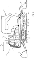
- Number 1 in Figure 1 indicates as a whole a ski slope snow groomer designed to travel in a travelling direction D.
- snow groomer 1 comprises a frame 2; two variable-configuration wheel assemblies 3 on opposite sides of frame 2; and two tracks 4 wound about respective wheel assemblies 3, and only one of which is shown in Figure 1 .
- Each wheel assembly 3 comprises a front wheel 3; a rear wheel 3; and four middle wheels 3 between front wheel 3 and rear wheel 3, which is a drive wheel.
- snow groomer 1 comprises a control assembly 5; a cab 6; a user interface 7 inside cab 6; a shovel 8 fitted to the front of frame 2; a tiller 9 fitted to the rear of frame 2; a winch assembly 10 fitted to the top of frame 2; an internal combustion engine 11; and a power train 12 connected functionally to internal combustion engine 11, drive wheels 3, shovel 8, tiller 9, and winch assembly 10.
- Power train 12 may be hydraulic or electric, or a combination of the two.
- Control assembly 5 comprises a control unit 13 and user interface 7, and is designed to acquire a signal indicating an operating state of snow groomer 1 as a function of at least one operating parameter, and preferably a number of operating parameters, of the snow groomer, and to adjust the configuration of wheel assemblies 3 as a function of the operating state signal.
- each track 4 also extends to end wheels 3.
- the configuration of tracks 4 depends on the configuration of respective wheel assemblies 3, each of which is adjustable between two limit configurations.
- frame 2 extends along an axis A, and supports wheel assemblies 3.
- each front wheel 3 is connected to frame 2 by a carriage 14 fitted to frame 2, and which is movable, by an actuator not shown, along axis A to keep respective track 4 taut regardless of the configuration of the other wheels 3 in wheel assembly 3.
- Rear wheels 3 are fitted directly to frame 2.
- the middle wheels 3 in each assembly are connected in pairs to respective rocker arms 15, in turn connected movably to frame 2.
- Snow groomer 1 comprises a variable-configuration, variable-rigidity shock absorber assembly 16 for connecting middle wheels 3 - in this case, rocker arms 15 - to frame 2, absorbing any shock, and selectively adjusting the position of middle wheels 3 with respect to frame 2.
- shock absorber assembly 16 comprises four shock absorber devices 17, each connecting a respective rocker arm 15 to frame 2.
- each middle wheel 3 is associated with a respective shock absorber device 17.
- Control assembly 5 is designed to control shock absorber assembly 16, which adjusts the configuration of wheel assemblies 3 by means of shock absorber devices 17.
- shock absorber assembly 16 is controlled hydraulically to adjust the configuration of wheel assemblies 3 and the rigidity of each shock absorber device 17.
- Control assembly 5 is designed to adjust shock absorber devices 17 independently or jointly. In the case of joint adjustment, this means at least two shock absorber devices 17 are adjusted to the same position and the same rigidity.
- Shock absorber devices 17 can be adjusted jointly in various combinations. The most commonly used options are those jointly operating shock absorber devices 17 associated with opposite rocker arms 15 on either side of axis A, or only one pair of shock absorber devices associated with opposite rocker arms.
- a hydraulic circuit 19 comprises a pump 20; a tank 21; and lines connecting pump 20 and tank 21 to each shock absorber device 17.
- each shock absorber device 17 comprises a mechanical connection 22 between frame 2 and rocker arm 15 and a portion of hydraulic circuit 19.
- Mechanical connection 22 comprises a hydraulic cylinder 23; a crank 24; and a supporting plate 25 supporting crank 24.
- Rocker arm 15 comprises two mounts 26 for attaching respective middle wheels 3 about two axes of rotation A1 crosswise to axis A ( Figure 1 ).
- Crank 24 comprises a shaft 27, which has an axis A2 parallel to axes A1, and is mounted to rotate about axis A2 inside supporting plate 25 fixed to frame 2; an arm 28 connected rigidly to shaft 27, and connected to rocker arm 15 to rotate about an axis A3 parallel to and equidistant from axes A1; and an arm 29 integral with shaft 27 and fitted to one end of hydraulic cylinder 23 to rotate about an axis A4 parallel to axes A1.
- hydraulic cylinder 23 The other end of hydraulic cylinder 23 is fixed to frame 2 to rotate about an axis A5 parallel to axes A1.
- Hydraulic cylinder 23 is a double-acting hydraulic cylinder, and comprises a cylinder 30; a rod 31; a plate 32 integral with cylinder 30; a plate 33 integral with rod 31; and an elastic member 34 - in the example shown, a spring - precompressed between plates 32 and 33.
- hydraulic cylinder 23 is connected to two branches 35, 36 of hydraulic circuit 19 to selectively fill and drain a first and second chamber 37, 38 of hydraulic cylinder 23.
- Shock absorber device 17 also comprises two expansion vessels 39, 40 of the hydraulic cylinder, located along respective branches 35, 36; and two servovalves 41, 42 also located along respective branches 35, 36.
- Each expansion vessel 39, 40 may be of the type divided internally by a membrane into two compartments, one containing air or other gas, and the other containing substantially non-compressible hydraulic fluid. Depending on the amount of hydraulic fluid in the compartment, it is thus possible to set hydraulic cylinder 23 to a position of equilibrium and adjust the rigidity of hydraulic cylinder 23, which operates as a shock absorber.
- Servovalves 41, 42 are both three-way, three-position servovalves for selectively supplying, draining, and cutting off hydraulic fluid flow of respective chambers 37, 38, and are selectively controlled by control assembly 5.
- control assembly 5 comprises position sensors 43, each associated with a respective hydraulic cylinder 23 to determine the position of hydraulic cylinder 23 and emit a signal indicating the position of shock absorber device 17 with respect to frame 2. And control unit 13 calculates a signal indicating the configuration of shock absorber assembly 16 as a function of the signals indicating the position of shock absorber devices 17 ( Figure 3 ).
- control assembly 5 comprises, for each shock absorber device 17, a pressure sensor 44 for determining the pressure P1 in chamber 37; and a pressure sensor 45 for determining the pressure P2 in chamber 38.
- control unit 13 acquires the pressure signals from sensors 44 and sensors 45, and accordingly calculates a signal indicating the rigidity of each shock absorber device, and a signal indicating the rigidity of shock absorber assembly 16.
- control assembly 5 comprises a speed sensor 46 for determining the travelling speed of snow groomer 1, and emitting a speed signal.
- control assembly 5 comprises a sensor 47 for determining the steering angle of snow groomer 1, and emitting a signal indicating the steering angle.
- control assembly 5 comprises an inclinometer 48 for determining lateral tilt of snow groomer 1, and emitting a signal indicating the lateral tilt of snow groomer 1.
- control assembly 5 comprises an inclinometer 49 for determining longitudinal tilt of snow groomer 1, and emitting a signal indicating the longitudinal tilt of snow groomer 1.
- Control unit 13 acquires the signal indicating the configuration of shock absorber assembly 16, the signal indicating the rigidity of shock absorber assembly 16, the signal indicating the speed of snow groomer 1, the steering angle signal, the signal indicating lateral tilt of snow groomer 1, and the signal indicating longitudinal tilt of snow groomer 1, and accordingly calculates a signal indicating the operating state of snow groomer 1.
- the operating state of snow groomer 1 is a function of a number of operating parameters.
- control unit calculates the operating state signal as a function of at least the speed signal, the angle signal, and the rigidity signals.
- control unit 13 compares the signals with threshold values, rates the signals on the basis of priority, and calculates the operating state signal by eliminating any low-priority signals or by assigning different weights to the signals.
- User interface 7 is designed to emit a control signal
- control unit 13 is designed to recalculate the operating state signal as a function of the control signal.
- the driver of snow groomer 1 is permitted to personally select given attitudes of snow groomer 1; and the operating state signal is recalculated as a function of the driver-selected attitude.
- the attitude of snow groomer 1 is a combination of the configuration of wheel assemblies 3, i.e. of shock absorber assembly 16, and the rigidity of shock absorber 16.
- control unit 13 After calculating the signal indicating the operating state of snow groomer 1, control unit 13 adjusts shock absorber assembly 16 accordingly.
- each wheel assembly 3 assumes a configuration enabling maximum contact between tracks 4 and snow cover M at very high speed.
- wheel assemblies 3 In the event of severe lateral tilt, wheel assemblies 3 assume respective asymmetrical configurations to compensate for it.
- each wheel assembly 3 assumes a configuration designed to reduce it.
- User interface 7 in Figure 1 allows the driver to override automatic adjustment of shock absorber assembly 16 and adjust it manually.
- the driver of snow groomer 1 can also opt to jointly operate two or more shock absorber devices 17, i.e. with the same position and rigidity parameters, or to operate shock absorber devices 17 independently or in independent groups.
- the driver controls both the position and rigidity of shock absorber assembly 16 with the aid of a display, on user interface 7, showing the data supplied by sensors 43, 44, 45 relative to the actual position and rigidity of shock absorber assembly 16.
Landscapes
- Engineering & Computer Science (AREA)
- Mechanical Engineering (AREA)
- Chemical & Material Sciences (AREA)
- Combustion & Propulsion (AREA)
- Transportation (AREA)
- Architecture (AREA)
- Civil Engineering (AREA)
- Structural Engineering (AREA)
- Vehicle Body Suspensions (AREA)
- Preparation Of Compounds By Using Micro-Organisms (AREA)
- Automobile Manufacture Line, Endless Track Vehicle, Trailer (AREA)
Claims (10)
- Skihang-Pistenfahrzeug (1), das umfasst:- einen Rahmen (2);- zwei Radanordnungen (3) auf entgegengesetzten Seiten des Rahmens (2);- zwei Laufketten (4), die jeweils um die zwei Radanordnungen (3) gewickelt sind;eine Stoßdämpferanordnung (16) mit variabler Konfiguration und variabler Starrheit, die mit den Radanordnungen (3) und dem Rahmen (2) verbunden ist und konstruiert ist, um die Radanordnungen (3) einzustellen; und- eine Steueranordnung (5) umfassend eine Vielzahl von Sensoren, mit:wobei die Steuereinheit (13) konfiguriert ist, um ein Betriebszustandssignal als eine Funktion einer Vielzahl von Signalen zu berechnen, welche das Geschwindigkeitssignal, das Winkelsignal und Signale der Drucksensoren (44, 45) umfassen, und um die Starrheit der Stoßdämpferanordnung (16) als eine Funktion des Betriebszustandssignals einzustellen.einem Geschwindigkeitssensor (46) zum Erfassen eines Signals, das die Fahrgeschwindigkeit des Pistenfahrzeugs (1) anzeigt;einem Sensor (47) zum Erfassen eines Signals, das den Lenkwinkel des Pistenfahrzeugs (1) anzeigt; undDrucksensoren (44, 45) zum Erfassen von Signalen, die mit der Starrheit der Stoßdämpferanordnung (16) korrelieren,
- Pistenfahrzeug nach Anspruch 1, wobei die Steueranordnung (5) wenigstens einen Positionssensor (43) zum Erfassen eines Signals umfasst, das die Konfiguration der Stoßdämpferanordnung (16) anzeigt; wobei die Steuereinheit (13) konfiguriert ist, um das Signal, das den Betriebszustand des Pistenfahrzeugs (1) anzeigt, als eine Funktion des Signals des Positionssensors (43) zu berechnen.
- Pistenfahrzeug nach einem der vorangehenden Ansprüche, wobei die Stoßdämpferanordnung (16) eine Anzahl von Stoßdämpfervorrichtungen (17) umfasst; und die Steueranordnung (5) eine Anzahl von Positionssensoren (43) umfasst; wobei jede Stoßdämpfervorrichtung (17) mit wenigstens einem Rad (3) und dem Rahmen (2) verbunden ist und wenigstens einem der Positionssensoren (43) zugeordnet ist, um ein Signal zu erfassen, das die Position der jeweiligen Stoßdämpfervorrichtung (17) anzeigt; und wobei die Steuereinheit (13) konfiguriert ist, um das Signal, das die Konfiguration der Stoßdämpferanordnung (16) anzeigt, als eine Funktion der Signale, welche die Positionen der Stoßdämpfervorrichtungen (17) anzeigen, zu berechnen.
- Pistenfahrzeug nach Anspruch 3, wobei die Steueranordnung (5) Drucksensoren (44, 45) umfasst, die den Stoßdämpfervorrichtungen (17) zugeordnet sind, und konfiguriert ist, um Signale zu erfassen, die die Betriebsdrücke der Stoßdämpfervorrichtungen (17) anzeigen; wobei die Steuereinheit (13) konfiguriert ist, um die Starrheit der Stoßdämpferanordnung (16) als eine Funktion der Signale, die die Betriebsdrücke der Stoßdämpfervorrichtungen (17) anzeigen, zu berechnen.
- Pistenfahrzeug nach einem der vorangehenden Ansprüche, wobei die Steueranordnung (5) eine Benutzerschnittstelle (7) umfasst, um ein Signal zu liefern, das einen Bedienerbefehl anzeigt; wobei die Steuereinheit (13) konfiguriert ist, um das Betriebszustandssignal als eine Funktion des Bedienerbefehlssignals neu zu berechnen.
- Verfahren zur Steuerung eines Skihang-Pistenfahrzeugs, wobei das Pistenfahrzeug (1) umfasst:- einen Rahmen (2);- zwei Radanordnungen (3) mit variabler Konfiguration auf entgegengesetzten Seiten des Rahmens (2); und- zwei Laufketten (4), die jeweils um die zwei Radanordnungen (3) gewickelt sind;wobei das Verfahren die folgenden Schritte umfasst:- Einstellen der Radanordnungen (3) mittels einer Stoßdämpferanordnung (16) mit variabler Konfiguration, die mit den Radanordnungen (3) und dem Rahmen (2) verbunden ist;- Erfassen einer Vielzahl von Signalen, die umfassen: ein Signal, das die Fahrgeschwindigkeit des Pistenfahrzeugs (1) anzeigt; ein Signal, das den Lenkwinkel des Pistenfahrzeugs (1) anzeigt; Signale, welche die Betriebsdrücke der Stoßdämpferanordnungen (17) anzeigen;- Berechnen eines Betriebszustandssignals des Pistenfahrzeugs (1) als eine Funktion einer Vielzahl von Signalen, welche das Geschwindigkeitssignal, das Winkelsignal und Signale, die den Betriebsdruck anzeigen, umfassen; und- Einstellen der Starrheit der Stoßdämpferanordnung (16) als eine Funktion des Betriebszustandssignals.
- Verfahren nach Anspruch 6, ferner umfassend die Schritte: Erfassen eines Signals, das die Konfiguration der Stoßdämpferanordnung (16) anzeigt; und Berechnen des Signals, das den Betriebszustand des Pistenfahrzeugs (1) als eine Funktion des Signals anzeigt, das die Konfiguration der Stoßdämpferanordnung (16) anzeigt.
- Verfahren nach Anspruch 6 oder 7, wobei die Stoßdämpferanordnung (16) eine variable Starrheit hat; wobei das Verfahren die Schritte umfasst: Erfassen eines Signals, das die Starrheit der Stoßdämpferanordnung (16) anzeigt; Berechnen des Betriebszustandssignals als eine Funktion des Signals, das die Starrheit der Stoßdämpferanordnung (16) anzeigt; und Einstellen der Starrheit der Stoßdämpferanordnung (16) als eine Funktion des Betriebszustandssignals.
- Verfahren nach einem der Ansprüche 6 bis 8, wobei die Stoßdämpferanordnung (16) eine Anzahl von Stoßdämpfervorrichtungen (17) umfasst; wobei das Verfahren die folgenden Schritte umfasst: Erfassen von Signalen, die die Positionen der Stoßdämpfervorrichtungen (17) anzeigen; und Berechnen des Signals, das die Konfiguration der Stoßdämpferanordnung (16) anzeigt, als eine Funktion der Signale, die die Positionen der Stoßdämpfervorrichtungen (17) anzeigen.
- Verfahren nach einem der Ansprüche 6 bis 9, ferner umfassend die Schritte: Erfassen eines Signals, das einen Bedienerbefehl anzeigt; und Neuberechnen des Betriebszustandssignals als eine Funktion des Bedienerbefehlssignals.
Applications Claiming Priority (2)
| Application Number | Priority Date | Filing Date | Title |
|---|---|---|---|
| ITMI2009A002133A IT1397197B1 (it) | 2009-12-02 | 2009-12-02 | Veicolo battipista e relativo metodo di controllo. |
| PCT/IB2010/003063 WO2011067652A1 (en) | 2009-12-02 | 2010-11-30 | Snow groomer and relative control method |
Publications (3)
| Publication Number | Publication Date |
|---|---|
| EP2507118A1 EP2507118A1 (de) | 2012-10-10 |
| EP2507118B1 EP2507118B1 (de) | 2014-05-07 |
| EP2507118B2 true EP2507118B2 (de) | 2021-07-28 |
Family
ID=42102674
Family Applications (1)
| Application Number | Title | Priority Date | Filing Date |
|---|---|---|---|
| EP10807652.2A Active EP2507118B2 (de) | 2009-12-02 | 2010-11-30 | Pistenfahrzeug und dazugehöriges regelverfahren |
Country Status (5)
| Country | Link |
|---|---|
| US (1) | US8579057B2 (de) |
| EP (1) | EP2507118B2 (de) |
| CA (1) | CA2782167C (de) |
| IT (1) | IT1397197B1 (de) |
| WO (1) | WO2011067652A1 (de) |
Families Citing this family (17)
| Publication number | Priority date | Publication date | Assignee | Title |
|---|---|---|---|---|
| CA2846662C (en) * | 2011-08-31 | 2018-05-22 | Snowgrolic S.A R.L. | Tracked vehicle |
| FI124889B (fi) * | 2012-05-31 | 2015-03-13 | Ponsse Oyj | Sovitelma metsäkoneessa ja vastaavalla sovitelmalla varustettu metsäkone |
| US9661798B2 (en) | 2013-11-13 | 2017-05-30 | Cnh Industrial America Llc | Agricultural tillage implement wheel control |
| RU2014144625A (ru) | 2013-11-13 | 2016-05-27 | СиЭнЭйч ИНДАСТРИАЛ АМЕРИКА ЭлЭлСи | Система подъема качающегося рычага |
| US9439340B2 (en) | 2013-11-13 | 2016-09-13 | Cnh Industrial America Llc | Frame configuration for an agricultural tillage implement |
| CA2867274C (en) | 2013-11-13 | 2018-07-24 | Cnh Industrial America Llc | Agricultural tillage implement wheel control |
| CA2867278C (en) | 2013-12-11 | 2020-01-07 | Cnh Industrial Canada, Ltd. | Remote leveling of tillage implements using inclinometers |
| US10420271B2 (en) | 2014-11-10 | 2019-09-24 | Cnh Industrial America Llc | Fully adjustable lift system |
| DE102015103556A1 (de) * | 2015-03-11 | 2016-09-15 | Manitowoc Crane Group France Sas | Vorrichtung und Verfahren zur Bestimmung der Bodendruckverteilung bei einer mobilen Arbeitsmaschine |
| USD845353S1 (en) * | 2016-04-11 | 2019-04-09 | Prinoth S.P.A. | Snow groomer |
| US10858225B2 (en) * | 2018-06-12 | 2020-12-08 | Caterpillar Inc. | Winch line speed control for a track-type machine having an electric drive powertrain |
| IT201800009419A1 (it) * | 2018-10-12 | 2020-04-12 | Prinoth Spa | Veicolo cingolato per la preparazione di piste da sci |
| KR102056762B1 (ko) | 2018-12-03 | 2019-12-16 | 한림대학교 산학협력단 | 딥러닝 기반 맥락인식 댐퍼 제어 동계스포츠 시스템 |
| US12485977B2 (en) | 2019-07-19 | 2025-12-02 | Prinoth Ltd. | Tracked vehicle arrangement including main vehicle and trailer |
| EP4051533A4 (de) | 2019-10-30 | 2023-11-22 | Prinoth Ltd | System und verfahren zur neigungssteuerung eines arbeitsgerätes für ein kettenfahrzeug |
| IT201900021939A1 (it) * | 2019-11-22 | 2021-05-22 | Prinoth Spa | Veicolo cingolato comprendente un'interfaccia utente |
| EP4170093B1 (de) * | 2021-10-21 | 2024-12-11 | PRINOTH S.p.A. | Raupenfahrzeug und steuerungsverfahren für besagtes fahrzeug |
Citations (1)
| Publication number | Priority date | Publication date | Assignee | Title |
|---|---|---|---|---|
| DE102004059823A1 (de) † | 2004-12-03 | 2006-06-08 | Kässbohrer Geländefahrzeug AG | Raupenfahrzeug |
Family Cites Families (17)
| Publication number | Priority date | Publication date | Assignee | Title |
|---|---|---|---|---|
| US3447621A (en) * | 1967-08-15 | 1969-06-03 | Katrak Vehicle Co | Triple walking beam suspension and drive assembly for track laying vehicles |
| US4029165A (en) * | 1976-02-05 | 1977-06-14 | Miller Formless Co., Inc. | Convertible construction machine |
| US4681177A (en) * | 1985-12-09 | 1987-07-21 | Caterpillar Inc. | Method and apparatus for tensioning frictionally driven, ground engaging belts |
| IT1234428B (it) | 1989-07-24 | 1992-05-18 | Leitner Spa | Veicolo cingolato, in particolare per la preparazione di piste da sci |
| JP2772155B2 (ja) * | 1991-05-13 | 1998-07-02 | 防衛庁技術研究本部長 | 装軌式車両の懸架装置 |
| NL9201553A (nl) * | 1992-09-04 | 1994-04-05 | Knijpstra Konstr Bv | Rupsbandvoertuig. |
| DE4330833A1 (de) * | 1993-07-16 | 1995-03-23 | Intertractor Ag | Vorrichtung zum Spannen und Abfedern des Leitrades von Kettenfahrzeugen |
| RU2041080C1 (ru) * | 1993-08-06 | 1995-08-09 | Всероссийский научно-исследовательский институт транспортного машиностроения | Способ демпфирования колебаний многоопорного транспортного средства и его система подрессоривания |
| US5409075A (en) * | 1993-11-12 | 1995-04-25 | Nieman; Donnie L. | Pneumatic suspension system for farm equipment |
| JP3632801B2 (ja) * | 1996-09-25 | 2005-03-23 | ヤンマー農機株式会社 | クローラ式走行装置のイコライザ支持構成 |
| US5927412A (en) * | 1997-01-14 | 1999-07-27 | Caterpillar Inc. | Castering swing link for a track sub-assembly |
| US6247547B1 (en) * | 1998-04-21 | 2001-06-19 | A.S.V., Inc. | Suspension and drive mechanism for a multi-surface vehicle |
| JP4334677B2 (ja) | 1999-06-07 | 2009-09-30 | 大日本印刷株式会社 | 食品用袋 |
| US6832659B1 (en) * | 2001-11-01 | 2004-12-21 | Clark Equipment Company | Loader frame and bolt-on track drive |
| ITMI20070188U1 (it) * | 2007-05-25 | 2008-11-26 | Rolic Invest Sarl | Veicolo battipista |
| US7967087B2 (en) * | 2008-06-27 | 2011-06-28 | Caterpillar Sarl | Suspension for a machine |
| CA2693526C (en) * | 2009-02-18 | 2014-12-02 | L'equipe Fabconcept Inc. | Endless belt tensioner system and method of use thereof |
-
2009
- 2009-12-02 IT ITMI2009A002133A patent/IT1397197B1/it active
-
2010
- 2010-11-30 EP EP10807652.2A patent/EP2507118B2/de active Active
- 2010-11-30 CA CA2782167A patent/CA2782167C/en active Active
- 2010-11-30 WO PCT/IB2010/003063 patent/WO2011067652A1/en not_active Ceased
- 2010-11-30 US US13/513,074 patent/US8579057B2/en active Active
Patent Citations (1)
| Publication number | Priority date | Publication date | Assignee | Title |
|---|---|---|---|---|
| DE102004059823A1 (de) † | 2004-12-03 | 2006-06-08 | Kässbohrer Geländefahrzeug AG | Raupenfahrzeug |
Also Published As
| Publication number | Publication date |
|---|---|
| EP2507118B1 (de) | 2014-05-07 |
| EP2507118A1 (de) | 2012-10-10 |
| CA2782167C (en) | 2018-03-13 |
| US20120305321A1 (en) | 2012-12-06 |
| US8579057B2 (en) | 2013-11-12 |
| WO2011067652A1 (en) | 2011-06-09 |
| CA2782167A1 (en) | 2011-06-09 |
| IT1397197B1 (it) | 2013-01-04 |
| ITMI20092133A1 (it) | 2011-06-03 |
Similar Documents
| Publication | Publication Date | Title |
|---|---|---|
| EP2507118B1 (de) | Pistenfahrzeug und dazugehöriges regelverfahren | |
| CA2283134C (en) | An agricultural machine with a self-leveling cab | |
| US9624643B2 (en) | Blade tilt system and method for a work vehicle | |
| US9328479B1 (en) | Grade control system and method for a work vehicle | |
| AU2010241344B2 (en) | Cab suspension for a swather tractor | |
| US9193381B2 (en) | Method and apparatus for affecting cornering performance of a motor vehicle, and a motor vehicle | |
| US9551130B2 (en) | Blade stabilization system and method for a work vehicle | |
| EP2704911B1 (de) | Aufbau eines lenkbaren rades für ein fahrzeug, und fahrzeug mit einem solchen system | |
| US10829115B2 (en) | Work vehicle | |
| EP3055194B1 (de) | Anordnung für ein geländekraftfahrzeug und geländekraftfahrzeug mit solch einer anordnung | |
| US10486697B2 (en) | Work vehicle | |
| JP2009055795A (ja) | 作業車両 | |
| JP5297280B2 (ja) | 作業機の傾斜角度検出構造 | |
| JP2009126248A (ja) | 作業車両の独立型サスペンション | |
| JP5123900B2 (ja) | 作業機のロール角度検出構造 | |
| US12234621B2 (en) | Grade control system and method for a work vehicle | |
| JPH0116121B2 (de) | ||
| JP3570958B2 (ja) | クローラ走行型作業車 | |
| JP3767245B2 (ja) | 耕深制御装置 | |
| JP3374287B2 (ja) | 乗用田植機 | |
| JP2006320236A (ja) | ロータリ作業機の耕深制御装置 | |
| JPH0458922B2 (de) | ||
| JPS61163029A (ja) | 遠隔操縦式作業車 | |
| JP2004135674A (ja) | トラクタの自動旋回制御装置 | |
| SE1000591A1 (sv) | Ett system och ett förfarande för att motverka oscillationer eller oscillationstendenser hos en arbetsmaskin |
Legal Events
| Date | Code | Title | Description |
|---|---|---|---|
| PUAI | Public reference made under article 153(3) epc to a published international application that has entered the european phase |
Free format text: ORIGINAL CODE: 0009012 |
|
| 17P | Request for examination filed |
Effective date: 20120618 |
|
| AK | Designated contracting states |
Kind code of ref document: A1 Designated state(s): AL AT BE BG CH CY CZ DE DK EE ES FI FR GB GR HR HU IE IS IT LI LT LU LV MC MK MT NL NO PL PT RO RS SE SI SK SM TR |
|
| DAX | Request for extension of the european patent (deleted) | ||
| RAP1 | Party data changed (applicant data changed or rights of an application transferred) |
Owner name: SNOWGROLIC S.A R.L. |
|
| RIC1 | Information provided on ipc code assigned before grant |
Ipc: E01H 4/02 20060101ALI20130930BHEP Ipc: B62D 55/112 20060101AFI20130930BHEP Ipc: B60G 11/56 20060101ALI20130930BHEP Ipc: B60G 17/04 20060101ALI20130930BHEP Ipc: B62D 55/06 20060101ALI20130930BHEP Ipc: B62D 55/116 20060101ALI20130930BHEP Ipc: B60G 5/01 20060101ALI20130930BHEP |
|
| GRAP | Despatch of communication of intention to grant a patent |
Free format text: ORIGINAL CODE: EPIDOSNIGR1 |
|
| INTG | Intention to grant announced |
Effective date: 20131126 |
|
| GRAS | Grant fee paid |
Free format text: ORIGINAL CODE: EPIDOSNIGR3 |
|
| GRAA | (expected) grant |
Free format text: ORIGINAL CODE: 0009210 |
|
| AK | Designated contracting states |
Kind code of ref document: B1 Designated state(s): AL AT BE BG CH CY CZ DE DK EE ES FI FR GB GR HR HU IE IS IT LI LT LU LV MC MK MT NL NO PL PT RO RS SE SI SK SM TR |
|
| REG | Reference to a national code |
Ref country code: GB Ref legal event code: FG4D |
|
| REG | Reference to a national code |
Ref country code: AT Ref legal event code: REF Ref document number: 666412 Country of ref document: AT Kind code of ref document: T Effective date: 20140515 |
|
| REG | Reference to a national code |
Ref country code: IE Ref legal event code: FG4D |
|
| REG | Reference to a national code |
Ref country code: DE Ref legal event code: R096 Ref document number: 602010015979 Country of ref document: DE Effective date: 20140626 |
|
| REG | Reference to a national code |
Ref country code: CH Ref legal event code: NV Representative=s name: HEPP WENGER RYFFEL AG, CH |
|
| REG | Reference to a national code |
Ref country code: SE Ref legal event code: TRGR |
|
| REG | Reference to a national code |
Ref country code: NO Ref legal event code: T2 Effective date: 20140507 |
|
| REG | Reference to a national code |
Ref country code: NL Ref legal event code: VDEP Effective date: 20140507 |
|
| REG | Reference to a national code |
Ref country code: LT Ref legal event code: MG4D |
|
| PG25 | Lapsed in a contracting state [announced via postgrant information from national office to epo] |
Ref country code: FI Free format text: LAPSE BECAUSE OF FAILURE TO SUBMIT A TRANSLATION OF THE DESCRIPTION OR TO PAY THE FEE WITHIN THE PRESCRIBED TIME-LIMIT Effective date: 20140507 Ref country code: LT Free format text: LAPSE BECAUSE OF FAILURE TO SUBMIT A TRANSLATION OF THE DESCRIPTION OR TO PAY THE FEE WITHIN THE PRESCRIBED TIME-LIMIT Effective date: 20140507 Ref country code: IS Free format text: LAPSE BECAUSE OF FAILURE TO SUBMIT A TRANSLATION OF THE DESCRIPTION OR TO PAY THE FEE WITHIN THE PRESCRIBED TIME-LIMIT Effective date: 20140907 Ref country code: CY Free format text: LAPSE BECAUSE OF FAILURE TO SUBMIT A TRANSLATION OF THE DESCRIPTION OR TO PAY THE FEE WITHIN THE PRESCRIBED TIME-LIMIT Effective date: 20140507 Ref country code: GR Free format text: LAPSE BECAUSE OF FAILURE TO SUBMIT A TRANSLATION OF THE DESCRIPTION OR TO PAY THE FEE WITHIN THE PRESCRIBED TIME-LIMIT Effective date: 20140808 |
|
| PG25 | Lapsed in a contracting state [announced via postgrant information from national office to epo] |
Ref country code: ES Free format text: LAPSE BECAUSE OF FAILURE TO SUBMIT A TRANSLATION OF THE DESCRIPTION OR TO PAY THE FEE WITHIN THE PRESCRIBED TIME-LIMIT Effective date: 20140507 Ref country code: HR Free format text: LAPSE BECAUSE OF FAILURE TO SUBMIT A TRANSLATION OF THE DESCRIPTION OR TO PAY THE FEE WITHIN THE PRESCRIBED TIME-LIMIT Effective date: 20140507 Ref country code: PL Free format text: LAPSE BECAUSE OF FAILURE TO SUBMIT A TRANSLATION OF THE DESCRIPTION OR TO PAY THE FEE WITHIN THE PRESCRIBED TIME-LIMIT Effective date: 20140507 Ref country code: RS Free format text: LAPSE BECAUSE OF FAILURE TO SUBMIT A TRANSLATION OF THE DESCRIPTION OR TO PAY THE FEE WITHIN THE PRESCRIBED TIME-LIMIT Effective date: 20140507 Ref country code: LV Free format text: LAPSE BECAUSE OF FAILURE TO SUBMIT A TRANSLATION OF THE DESCRIPTION OR TO PAY THE FEE WITHIN THE PRESCRIBED TIME-LIMIT Effective date: 20140507 |
|
| PG25 | Lapsed in a contracting state [announced via postgrant information from national office to epo] |
Ref country code: PT Free format text: LAPSE BECAUSE OF FAILURE TO SUBMIT A TRANSLATION OF THE DESCRIPTION OR TO PAY THE FEE WITHIN THE PRESCRIBED TIME-LIMIT Effective date: 20140908 |
|
| PG25 | Lapsed in a contracting state [announced via postgrant information from national office to epo] |
Ref country code: BE Free format text: LAPSE BECAUSE OF FAILURE TO SUBMIT A TRANSLATION OF THE DESCRIPTION OR TO PAY THE FEE WITHIN THE PRESCRIBED TIME-LIMIT Effective date: 20140507 Ref country code: CZ Free format text: LAPSE BECAUSE OF FAILURE TO SUBMIT A TRANSLATION OF THE DESCRIPTION OR TO PAY THE FEE WITHIN THE PRESCRIBED TIME-LIMIT Effective date: 20140507 Ref country code: SK Free format text: LAPSE BECAUSE OF FAILURE TO SUBMIT A TRANSLATION OF THE DESCRIPTION OR TO PAY THE FEE WITHIN THE PRESCRIBED TIME-LIMIT Effective date: 20140507 Ref country code: EE Free format text: LAPSE BECAUSE OF FAILURE TO SUBMIT A TRANSLATION OF THE DESCRIPTION OR TO PAY THE FEE WITHIN THE PRESCRIBED TIME-LIMIT Effective date: 20140507 Ref country code: DK Free format text: LAPSE BECAUSE OF FAILURE TO SUBMIT A TRANSLATION OF THE DESCRIPTION OR TO PAY THE FEE WITHIN THE PRESCRIBED TIME-LIMIT Effective date: 20140507 Ref country code: RO Free format text: LAPSE BECAUSE OF FAILURE TO SUBMIT A TRANSLATION OF THE DESCRIPTION OR TO PAY THE FEE WITHIN THE PRESCRIBED TIME-LIMIT Effective date: 20140507 |
|
| REG | Reference to a national code |
Ref country code: DE Ref legal event code: R026 Ref document number: 602010015979 Country of ref document: DE |
|
| PLBI | Opposition filed |
Free format text: ORIGINAL CODE: 0009260 |
|
| PG25 | Lapsed in a contracting state [announced via postgrant information from national office to epo] |
Ref country code: NL Free format text: LAPSE BECAUSE OF FAILURE TO SUBMIT A TRANSLATION OF THE DESCRIPTION OR TO PAY THE FEE WITHIN THE PRESCRIBED TIME-LIMIT Effective date: 20140507 |
|
| 26 | Opposition filed |
Opponent name: KAESSBOHRER GELAENDEFAHRZEUG AG Effective date: 20150204 |
|
| PLAX | Notice of opposition and request to file observation + time limit sent |
Free format text: ORIGINAL CODE: EPIDOSNOBS2 |
|
| REG | Reference to a national code |
Ref country code: DE Ref legal event code: R026 Ref document number: 602010015979 Country of ref document: DE Effective date: 20150204 |
|
| PG25 | Lapsed in a contracting state [announced via postgrant information from national office to epo] |
Ref country code: LU Free format text: LAPSE BECAUSE OF FAILURE TO SUBMIT A TRANSLATION OF THE DESCRIPTION OR TO PAY THE FEE WITHIN THE PRESCRIBED TIME-LIMIT Effective date: 20141130 Ref country code: MC Free format text: LAPSE BECAUSE OF FAILURE TO SUBMIT A TRANSLATION OF THE DESCRIPTION OR TO PAY THE FEE WITHIN THE PRESCRIBED TIME-LIMIT Effective date: 20140507 |
|
| PLAF | Information modified related to communication of a notice of opposition and request to file observations + time limit |
Free format text: ORIGINAL CODE: EPIDOSCOBS2 |
|
| GBPC | Gb: european patent ceased through non-payment of renewal fee |
Effective date: 20141130 |
|
| PG25 | Lapsed in a contracting state [announced via postgrant information from national office to epo] |
Ref country code: SI Free format text: LAPSE BECAUSE OF FAILURE TO SUBMIT A TRANSLATION OF THE DESCRIPTION OR TO PAY THE FEE WITHIN THE PRESCRIBED TIME-LIMIT Effective date: 20140507 |
|
| REG | Reference to a national code |
Ref country code: IE Ref legal event code: MM4A |
|
| PLAB | Opposition data, opponent's data or that of the opponent's representative modified |
Free format text: ORIGINAL CODE: 0009299OPPO |
|
| PLBB | Reply of patent proprietor to notice(s) of opposition received |
Free format text: ORIGINAL CODE: EPIDOSNOBS3 |
|
| R26 | Opposition filed (corrected) |
Opponent name: KAESSBOHRER GELAENDEFAHRZEUG AG Effective date: 20150204 |
|
| REG | Reference to a national code |
Ref country code: FR Ref legal event code: PLFP Year of fee payment: 6 |
|
| PG25 | Lapsed in a contracting state [announced via postgrant information from national office to epo] |
Ref country code: IE Free format text: LAPSE BECAUSE OF NON-PAYMENT OF DUE FEES Effective date: 20141130 Ref country code: GB Free format text: LAPSE BECAUSE OF NON-PAYMENT OF DUE FEES Effective date: 20141130 |
|
| REG | Reference to a national code |
Ref country code: NO Ref legal event code: CHAD Owner name: PRINOTH S.P.A., IT |
|
| REG | Reference to a national code |
Ref country code: CH Ref legal event code: PUE Owner name: PRINOTH S.P.A., IT Free format text: FORMER OWNER: SNOWGROLIC S.A R.L., LU |
|
| RAP2 | Party data changed (patent owner data changed or rights of a patent transferred) |
Owner name: PRINOTH S.P.A. |
|
| REG | Reference to a national code |
Ref country code: DE Ref legal event code: R082 Ref document number: 602010015979 Country of ref document: DE Representative=s name: MUELLER-BORE & PARTNER PATENTANWAELTE PARTG MB, DE Ref country code: DE Ref legal event code: R081 Ref document number: 602010015979 Country of ref document: DE Owner name: PRINOTH S.P.A., VIPITENO, IT Free format text: FORMER OWNER: SNOWGROLIC S.A R.L., LUXEMBOURG, LU |
|
| PG25 | Lapsed in a contracting state [announced via postgrant information from national office to epo] |
Ref country code: SM Free format text: LAPSE BECAUSE OF FAILURE TO SUBMIT A TRANSLATION OF THE DESCRIPTION OR TO PAY THE FEE WITHIN THE PRESCRIBED TIME-LIMIT Effective date: 20140507 |
|
| REG | Reference to a national code |
Ref country code: FR Ref legal event code: TP Owner name: PRINOTH S.P.A., IT Effective date: 20160413 |
|
| PG25 | Lapsed in a contracting state [announced via postgrant information from national office to epo] |
Ref country code: BG Free format text: LAPSE BECAUSE OF FAILURE TO SUBMIT A TRANSLATION OF THE DESCRIPTION OR TO PAY THE FEE WITHIN THE PRESCRIBED TIME-LIMIT Effective date: 20140507 |
|
| PG25 | Lapsed in a contracting state [announced via postgrant information from national office to epo] |
Ref country code: MT Free format text: LAPSE BECAUSE OF FAILURE TO SUBMIT A TRANSLATION OF THE DESCRIPTION OR TO PAY THE FEE WITHIN THE PRESCRIBED TIME-LIMIT Effective date: 20140507 Ref country code: TR Free format text: LAPSE BECAUSE OF FAILURE TO SUBMIT A TRANSLATION OF THE DESCRIPTION OR TO PAY THE FEE WITHIN THE PRESCRIBED TIME-LIMIT Effective date: 20140507 Ref country code: HU Free format text: LAPSE BECAUSE OF FAILURE TO SUBMIT A TRANSLATION OF THE DESCRIPTION OR TO PAY THE FEE WITHIN THE PRESCRIBED TIME-LIMIT; INVALID AB INITIO Effective date: 20101130 |
|
| APBM | Appeal reference recorded |
Free format text: ORIGINAL CODE: EPIDOSNREFNO |
|
| APBP | Date of receipt of notice of appeal recorded |
Free format text: ORIGINAL CODE: EPIDOSNNOA2O |
|
| APAH | Appeal reference modified |
Free format text: ORIGINAL CODE: EPIDOSCREFNO |
|
| REG | Reference to a national code |
Ref country code: AT Ref legal event code: PC Ref document number: 666412 Country of ref document: AT Kind code of ref document: T Owner name: PRINOTH S.P.A., IT Effective date: 20160822 |
|
| REG | Reference to a national code |
Ref country code: FR Ref legal event code: PLFP Year of fee payment: 7 |
|
| APAL | Date of receipt of statement of grounds of an appeal modified |
Free format text: ORIGINAL CODE: EPIDOSCNOA3O |
|
| APBQ | Date of receipt of statement of grounds of appeal recorded |
Free format text: ORIGINAL CODE: EPIDOSNNOA3O |
|
| REG | Reference to a national code |
Ref country code: FR Ref legal event code: PLFP Year of fee payment: 8 |
|
| PG25 | Lapsed in a contracting state [announced via postgrant information from national office to epo] |
Ref country code: MK Free format text: LAPSE BECAUSE OF FAILURE TO SUBMIT A TRANSLATION OF THE DESCRIPTION OR TO PAY THE FEE WITHIN THE PRESCRIBED TIME-LIMIT Effective date: 20140507 |
|
| PG25 | Lapsed in a contracting state [announced via postgrant information from national office to epo] |
Ref country code: AL Free format text: LAPSE BECAUSE OF FAILURE TO SUBMIT A TRANSLATION OF THE DESCRIPTION OR TO PAY THE FEE WITHIN THE PRESCRIBED TIME-LIMIT Effective date: 20140507 |
|
| APBU | Appeal procedure closed |
Free format text: ORIGINAL CODE: EPIDOSNNOA9O |
|
| PLAY | Examination report in opposition despatched + time limit |
Free format text: ORIGINAL CODE: EPIDOSNORE2 |
|
| PLBC | Reply to examination report in opposition received |
Free format text: ORIGINAL CODE: EPIDOSNORE3 |
|
| PLAY | Examination report in opposition despatched + time limit |
Free format text: ORIGINAL CODE: EPIDOSNORE2 |
|
| PUAH | Patent maintained in amended form |
Free format text: ORIGINAL CODE: 0009272 |
|
| STAA | Information on the status of an ep patent application or granted ep patent |
Free format text: STATUS: PATENT MAINTAINED AS AMENDED |
|
| 27A | Patent maintained in amended form |
Effective date: 20210728 |
|
| AK | Designated contracting states |
Kind code of ref document: B2 Designated state(s): AL AT BE BG CH CY CZ DE DK EE ES FI FR GB GR HR HU IE IS IT LI LT LU LV MC MK MT NL NO PL PT RO RS SE SI SK SM TR |
|
| REG | Reference to a national code |
Ref country code: DE Ref legal event code: R102 Ref document number: 602010015979 Country of ref document: DE |
|
| REG | Reference to a national code |
Ref country code: SE Ref legal event code: RPEO |
|
| REG | Reference to a national code |
Ref country code: NO Ref legal event code: TB2 |
|
| P01 | Opt-out of the competence of the unified patent court (upc) registered |
Effective date: 20230518 |
|
| PGFP | Annual fee paid to national office [announced via postgrant information from national office to epo] |
Ref country code: SE Payment date: 20231123 Year of fee payment: 14 Ref country code: NO Payment date: 20231120 Year of fee payment: 14 |
|
| PG25 | Lapsed in a contracting state [announced via postgrant information from national office to epo] |
Ref country code: NO Free format text: LAPSE BECAUSE OF NON-PAYMENT OF DUE FEES Effective date: 20241130 |
|
| REG | Reference to a national code |
Ref country code: SE Ref legal event code: EUG |
|
| REG | Reference to a national code |
Ref country code: CH Ref legal event code: U11 Free format text: ST27 STATUS EVENT CODE: U-0-0-U10-U11 (AS PROVIDED BY THE NATIONAL OFFICE) Effective date: 20251201 |
|
| PGFP | Annual fee paid to national office [announced via postgrant information from national office to epo] |
Ref country code: DE Payment date: 20251126 Year of fee payment: 16 |
|
| PGFP | Annual fee paid to national office [announced via postgrant information from national office to epo] |
Ref country code: AT Payment date: 20251118 Year of fee payment: 16 |
|
| PGFP | Annual fee paid to national office [announced via postgrant information from national office to epo] |
Ref country code: IT Payment date: 20251106 Year of fee payment: 16 |
|
| PGFP | Annual fee paid to national office [announced via postgrant information from national office to epo] |
Ref country code: FR Payment date: 20251124 Year of fee payment: 16 |
|
| PGFP | Annual fee paid to national office [announced via postgrant information from national office to epo] |
Ref country code: CH Payment date: 20251201 Year of fee payment: 16 |