EP2506403B1 - Wechselstromgenerator für ein fahrzeug - Google Patents
Wechselstromgenerator für ein fahrzeug Download PDFInfo
- Publication number
- EP2506403B1 EP2506403B1 EP09851627.1A EP09851627A EP2506403B1 EP 2506403 B1 EP2506403 B1 EP 2506403B1 EP 09851627 A EP09851627 A EP 09851627A EP 2506403 B1 EP2506403 B1 EP 2506403B1
- Authority
- EP
- European Patent Office
- Prior art keywords
- cover
- alternator
- voltage regulator
- opposing
- components
- Prior art date
- Legal status (The legal status is an assumption and is not a legal conclusion. Google has not performed a legal analysis and makes no representation as to the accuracy of the status listed.)
- Not-in-force
Links
Images


Classifications
-
- H—ELECTRICITY
- H02—GENERATION; CONVERSION OR DISTRIBUTION OF ELECTRIC POWER
- H02K—DYNAMO-ELECTRIC MACHINES
- H02K5/00—Casings; Enclosures; Supports
- H02K5/04—Casings or enclosures characterised by the shape, form or construction thereof
-
- H—ELECTRICITY
- H02—GENERATION; CONVERSION OR DISTRIBUTION OF ELECTRIC POWER
- H02K—DYNAMO-ELECTRIC MACHINES
- H02K11/00—Structural association of dynamo-electric machines with electric components or with devices for shielding, monitoring or protection
- H02K11/04—Structural association of dynamo-electric machines with electric components or with devices for shielding, monitoring or protection for rectification
- H02K11/049—Rectifiers associated with stationary parts, e.g. stator cores
- H02K11/05—Rectifiers associated with casings, enclosures or brackets
Definitions
- the present invention relates to an alternator mounted on a vehicle or the like, and more particularly, to an attachment structure of a cover protecting components of an alternator and an alternator main body.
- an alternator for vehicle provided with a front bracket and a rear bracket that support a front bearing and a rear bearing rotatably supporting a rotor, which is a rotating body, in a rotatable manner and configured in such a manner that components immovably supported on the rear bracket on an opposite side to the rotor are covered with a cover made of an insulator, such as resin. It is required to form the cover in such a manner that the cover is configured to expose the alternator terminal B(where it is connected to the battery mounted on a vehicle) and also the terminal insertion opening of the connector (where it is connected to the vehicle connector), and thereby making no problems when in use.
- Patent Document 1 describes such a cover shaped like bottomed cylindrical and attached to the alternator main body with at three screw fixing portions and one hook-like fixing portion.
- Patent Document 1 EP1551092A2 ( Fig. 2 and Fig. 3 )
- cover is attached by means of screws penetrating through cover holes to screw holes provided at a higher position of a circuit board as a component not adjacent to the cover. Accordingly, the apparatus in the related art has problems that it is necessary to provide an extra extended portion to the circuit board and that a screwing process at several points is complex and improvement in producibility is not promoted. In addition, the cover and the alternator main body are unsettled and undergo displacement before the screws are fastened.
- hook-shaped fixing portion and a protrusion provided to a regulator housing portion or a brush tube-like housing portion are configured as attachment, other than the screw fixing portions .
- This configuration is relatively longer and larger than the screw fixing portion, and a space has been used only for these settings.
- the invention is devised to solve the problems as above and has an object to provide an alternator capable of enhancing productivity by making it easy to attach a cover to an alternator main body without causing positional displacement.
- the alternator for vehicle of the invention it becomes possible to obtain an alternator capable of enhancing productivity by making it easy to attach a cover to an alternator main body without causing positional displacement.
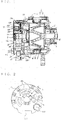
- Fig. 1 is a cross section of an alternator for vehicle according to a first embodiment.
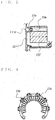
- Fig. 2 is a plane view of a rear cover of Fig. 1 when viewed from a rear end.
- the alternator includes a front bracket 2 and a rear bracket 3 as a case 1 supporting components, a stator 4 supported on both sides by case 1, and rotor 5 supported also on the case 1 via bearings 21 and 31.
- the rotor 5 includes a shaft 6 provided with a pulley 7 and is therefore configured to be driven to rotate by a belt (not shown).
- a field coil 8 is attached inside the rotor 5.
- a slip ring 9 is provided at one end of the shaft 6 and electrically connected to the field coil 8. A current is therefore supplied to the field coil 8 via the slip ring 9 and a brush 10, from a connector terminal 12, which is a connection portion to an external connector 11.
- a rectifier device 13 that rectifies an AC generated at a coil 41 in the stator 4 due to a rotating field developed when the rotor 5 is driven to rotate upon supply of a current to the field coil 8 to a DC, and a voltage regulator 14 that limits generated power to a specified value.
- the outer periphery of components described above are covered with a cover 15 made of an insulator, such as resin, and are therefore protected from an outside.
- a voltage regulator circuit portion 141 is provided adjacently to a brush housing portion 10a (see Fig. 7 ) in which to house the brush 10 and a cooling plate 142 (see Fig. 5 ) responsible for cooling is provided behind the voltage regulator circuit portion 141 with plural cooling fins 142a (see Fig. 6 ) protruding from the other surface.
- the connecter terminal 12 to which the external connector 11 is to be connected is disposed adjacently to the voltage regulator 14.
- the rectifier device 13 includes a positive-electrode cooling member 132 supporting plural (for example, six) positive-electrode rectifier elements 131, a negative-electrode cooling member 134 supporting plural (for example, six) negative-electrode rectifier elements 133, and a terminal board 135 having wiring members electrically connecting the rectifier elements 131 and 133 to the coil 41 in the stator 4.
- An output terminal bolt (hereinafter, referred to as the B terminal) extracting an output of the alternator to the outside is electrically connected to the positive-electrode cooling member 132. This terminal protrudes to the outside of alternator frame together with the connector terminal tip end described above.
- the cover 15 is shaped like bottomed cylindrical and attached from an opening side (on the right in Fig. 1 ) so as to protect the components.
- the B terminal Tb of the rectifier device 13 and the connector terminal 12 of the voltage regulator 14 are disposed so that tip ends, which are connection portions to external components, are exposed to the outside of the cover 15. Owing to this configuration, it becomes possible to protect the components without interfering with an electrical connection environment between the alternator and the vehicle.
- the cover 15 is formed to fit to layout of components, and attached to the alternator at a stage of substantially a final process.
- the cover attaching it is adjusted so as to expose the connector terminal tip end from the portion CT exposing connector terminal, and the B terminal tip end from portion BT exposing B terminal, as some example shown in Fig. 2 .
- Each tip end is not required to protrude to the outside from the cover 15 necessarily, of course. it is sufficient that there are no failure and there are no hindering configuration around opening when connecting.
- the cover 15 is not simply put on the alternator to which the components are attached.
- the cover 15 is attached by taking a layout and exposure of the components into consideration. Accordingly, positional displacement tends to occur.
- a convex portion 15a provided to an inner surface of the cover 15 is fit in a concave portion 13a provided to the cooling member 132 of the rectifier device 13 on the opposing surface in close proximity to the inner surface of the cover 15 at this stage. Because a fit end is the opposing surface in close proximity to the cover 15, displacement and adjustment during a positioning work of the cover 15 can be a minimum. Immediately after or simultaneously with the fitting, several points on a cover outermost peripheral portion are fit immovably in the outer peripheral portion of the rear bracket 3 by an unillustrated known method.
- the cover 15 is fixed on the outer peripheral portion of the rear bracket 3. It thus becomes possible to secure vibration resistance when mounted on a vehicle. Also, the concave portion 13a formed in the cooling member 132 is provided to the opposing surface in close proximity to the inner surface of the cover 15. Hence, there is no need to specially provide an extended portion, and space efficiency is not deteriorated.
- a component to which the fitting configuration is provided can be the connector terminal portion (see Fig. 6 ).
- Reliability is enhanced by providing the fitting configuration to more than one point.
- positional displacement can be suppressed in a reliable manner by providing the fitting configuration at a remote and substantially point-symmetric position with respect to the connector terminal exposing portion CT or the B terminal terminal exposing portion BT. It goes without saying that the fitting configuration can be provided to more than one point at point symmetric positions.
- a backside of convex portions 15a through 15d provided to the inner surface of the cover 15, that is, the cover outer surface is of a concave shape 16w.
- outer surface concave portions (when viewed from an outer surface) 16a provided at two remote points can be used as cover holding portions when the cover 15 is attached to the alternator.
- the cover 15 can be readily transported on a manufacturing line as it is sandwiched by an unillustrated scissors-like tool inserted in the outer surface concave portions 16a.
- the tool itself and a tool operating range can be smaller than in a case where the outermost peripheral portion of the cover 15 is gripped.
- a manufacturing space and producibility can be enhanced.
- the rear bracket 3 supports both of the voltage regulator 14 and the rectifier device 13. It should be appreciated, however, that the rear bracket 3 may support one of them or, for example, the front bracket 2 may support the both, and that a supporting component is not limited to those described above as long as a relation between the cover 15 and the component is the same.
- connecter terminal 12 electrically connected to the voltage regulator 14 there are various configurations corresponding to a vehicle connector and the configuration is not limited to the one shown in the drawings .
- a location with respect to the connector terminal 12 and the B terminal Tb and a positional relation with the alternator are determined by taking both the vehicle specification and the configurations and locations of the components forming the alternator into consideration, and the location is not limited to the location shown in the drawings.
- a positioning configuration in which a convex portion provided to an inner surface of a cover is fit in a concave portion provided to a component in close proximity to the cover at a region opposing the inner surface of the cover is provided to an external connection terminal of the component protruding from inside to outside of a alternator cover, that is, at substantially a point-symmetric position with respect to the B terminal or the connector and as further defined in claim 1. It thus becomes possible to obtain an alternator for vehicle capable of enhancing productivity by making it easy to attach the cover including a terminal exposing portion to the alternator main body without causing positional displacement.
- the invention is applied to an alternator mounted on a vehicle.
Landscapes
- Engineering & Computer Science (AREA)
- Power Engineering (AREA)
- Motor Or Generator Frames (AREA)
- Synchronous Machinery (AREA)
Claims (4)
- Wechselstromgenerator für ein Fahrzeug mit einem Gehäuse (1), das Komponenten (13, 14) abstützt, einem Rotor (5), der drehbar an dem Gehäuse abgestützt ist, einem Stator (4), der an einem Außenumfang des Rotors angeordnet ist und an beiden Seiten durch das Gehäuse abgestützt ist, einer Statorwicklung, die an dem Stator vorgesehen ist, einer Gleichrichtervorrichtung (13), die zum Gleichrichten einer in der Statorwicklung erzeugten elektromotorischen Wechselstromkraft zu einem Gleichstrom geeignet ist, und einem Spannungsregler (14), der zum Begrenzen der Wechselstromgeneratorleistung auf einen bestimmten Wert geeignet ist, wobei die Gleichrichtervorrichtung (13) und/oder der Spannungsregler (14), die die Komponenten sind, an dem Gehäuse auf einer dem Rotor gegenüberliegenden Seite abgestützt sind/ist, und ihr/sein Außenumfang durch eine Abdeckung (15) abgedeckt ist, wobei,
ein konvexer Abschnitt (15a), der an einer Innenfläche der Abdeckung (15) vorgesehen ist, in einen konkaven Abschnitt (13a) eingepasst ist, der an den Komponenten in einem Bereich vorgesehen ist, der der Innenfläche der Abdeckung (15) in unmittelbarer Nähe der Innenfläche der Abdeckung (15) gegenüberliegt; und
die Passkonfiguration an mindestens einer punktsymmetrischen Position in Bezug auf einen externen Verbindungsanschluss der Komponenten vorgesehen ist, der von der Innenseite zu der Außenseite der Wechselstromgeneratorabdeckung (15) vorsteht; wobei:
die Komponente, die mit der Passkonfiguration versehen ist, der Spannungsregler (14) ist, der an dem Wechselstromgenerator angebracht ist; dadurch gekennzeichnet, dass:
die Passkonfiguration, die an dem Spannungsregler (14) vorgesehen ist, aus einem konkaven Abschnitt (13a) gebildet ist, der an einem Spannungsregler (14)-Kühlelement (132, 134) oder an einem Spannungsregler (14)-Verbindungsabschnitt in der gegenüberliegenden Fläche, die der Innenfläche der Abdeckung (15) in unmittelbarer Nähe gegenüberliegt, vorgesehen ist. - Wechselstromgenerator für ein Fahrzeug nach Anspruch 1, dadurch gekennzeichnet, dass:
die Passkonfiguration ferner an der Gleichrichtervorrichtung (13) vorgesehen ist, die aus einem konkaven Abschnitt gebildet ist, der an einem Gleichrichterelement-Kühlelement (132, 134) in der gegenüberliegenden Fläche, die der Innenfläche der Abdeckung (15) in unmittelbarer Nähe gegenüberliegt, vorgesehen ist. - Wechselstromgenerator für ein Fahrzeug nach Anspruch 1, dadurch gekennzeichnet, dass:
die Passkonfiguration ferner an dem Spannungsregler (14) vorgesehen ist, der aus einem konkaven Abschnitt gebildet ist, der an dem Bürstengehäuseabschnitt (10a) in der gegenüberliegenden Fläche, die der Innenfläche der Abdeckung (15) in unmittelbarer Nähe gegenüberliegt, vorgesehen ist. - Wechselstromgenerator für ein Fahrzeug nach einem der Ansprüche 1 bis 3, dadurch gekennzeichnet, dass:
der konvexe Abschnitt (15a), der an der Innenfläche der Abdeckung (15) vorgesehen ist, einen Abdeckungshalteabschnitt aufweist, der zum Halten der Abdeckung (15) von einer Außenflächenseite in einem Rückseitenabschnitt verwendet wird.
Applications Claiming Priority (1)
| Application Number | Priority Date | Filing Date | Title |
|---|---|---|---|
| PCT/JP2009/069782 WO2011064835A1 (ja) | 2009-11-24 | 2009-11-24 | 車両用交流発電機 |
Publications (3)
| Publication Number | Publication Date |
|---|---|
| EP2506403A1 EP2506403A1 (de) | 2012-10-03 |
| EP2506403A4 EP2506403A4 (de) | 2016-12-28 |
| EP2506403B1 true EP2506403B1 (de) | 2019-04-17 |
Family
ID=44065959
Family Applications (1)
| Application Number | Title | Priority Date | Filing Date |
|---|---|---|---|
| EP09851627.1A Not-in-force EP2506403B1 (de) | 2009-11-24 | 2009-11-24 | Wechselstromgenerator für ein fahrzeug |
Country Status (6)
| Country | Link |
|---|---|
| US (1) | US9000637B2 (de) |
| EP (1) | EP2506403B1 (de) |
| JP (1) | JP5395192B2 (de) |
| KR (1) | KR101294425B1 (de) |
| CN (1) | CN102668337B (de) |
| WO (1) | WO2011064835A1 (de) |
Families Citing this family (3)
| Publication number | Priority date | Publication date | Assignee | Title |
|---|---|---|---|---|
| CN102497053B (zh) * | 2011-12-13 | 2013-12-04 | 中电电机股份有限公司 | 滑环罩的支撑结构 |
| CN104040843B (zh) * | 2012-01-10 | 2018-02-13 | 三菱电机株式会社 | 车辆用交流发电机 |
| WO2018092208A1 (ja) | 2016-11-16 | 2018-05-24 | 三菱電機株式会社 | 回転電機の保護カバー |
Family Cites Families (17)
| Publication number | Priority date | Publication date | Assignee | Title |
|---|---|---|---|---|
| GB1149856A (en) * | 1965-04-28 | 1969-04-23 | Lucas Industries Ltd | Alternators |
| JPH066689Y2 (ja) * | 1987-10-21 | 1994-02-16 | 三菱電機株式会社 | 小型電動機 |
| JPH09182349A (ja) * | 1995-12-22 | 1997-07-11 | Asmo Co Ltd | 開放モータの配線位置切り換え構造 |
| JP3042149U (ja) * | 1997-04-04 | 1997-10-14 | 国産電機株式会社 | 回転電機 |
| JP3820712B2 (ja) * | 1997-11-27 | 2006-09-13 | 株式会社デンソー | 車両用交流発電機 |
| JP4427896B2 (ja) * | 2000-03-17 | 2010-03-10 | 株式会社デンソー | 車両用交流発電機 |
| JP3561249B2 (ja) | 2001-09-17 | 2004-09-02 | 三菱電機株式会社 | 交流発電機の固定子およびその製造方法 |
| DE10361860A1 (de) | 2003-12-30 | 2005-07-28 | Robert Bosch Gmbh | Schutzkappe, insbesondere für einen Drehstromgenerator |
| JP2005204385A (ja) * | 2004-01-14 | 2005-07-28 | Denso Corp | 車両用交流発電機 |
| EP1808950B1 (de) * | 2004-11-04 | 2015-01-07 | Mitsubishi Denki Kabushiki Kaisha | Spannungsregler eines wechselstromgenerators für ein fahrzeug |
| JP4180618B2 (ja) * | 2006-06-15 | 2008-11-12 | 三菱電機株式会社 | 車両用交流発電機 |
| JP5007537B2 (ja) * | 2006-08-24 | 2012-08-22 | 株式会社デンソー | 車両用交流発電機 |
| JP4483842B2 (ja) * | 2006-09-07 | 2010-06-16 | 株式会社デンソー | 車両用交流発電機 |
| JP4600373B2 (ja) * | 2006-09-12 | 2010-12-15 | 株式会社デンソー | 車両用交流発電機 |
| JP4543057B2 (ja) * | 2007-04-11 | 2010-09-15 | 三菱電機株式会社 | 車両用回転電機 |
| JP4313404B2 (ja) * | 2007-05-22 | 2009-08-12 | 三菱電機株式会社 | 車両用交流発電機 |
| JP4324210B2 (ja) * | 2007-05-22 | 2009-09-02 | 三菱電機株式会社 | 車両用交流発電機 |
-
2009
- 2009-11-24 EP EP09851627.1A patent/EP2506403B1/de not_active Not-in-force
- 2009-11-24 US US13/503,302 patent/US9000637B2/en not_active Expired - Fee Related
- 2009-11-24 WO PCT/JP2009/069782 patent/WO2011064835A1/ja not_active Ceased
- 2009-11-24 KR KR1020127010012A patent/KR101294425B1/ko not_active Expired - Fee Related
- 2009-11-24 JP JP2011543002A patent/JP5395192B2/ja not_active Expired - Fee Related
- 2009-11-24 CN CN200980162556.8A patent/CN102668337B/zh not_active Expired - Fee Related
Non-Patent Citations (1)
| Title |
|---|
| None * |
Also Published As
| Publication number | Publication date |
|---|---|
| JPWO2011064835A1 (ja) | 2013-04-11 |
| JP5395192B2 (ja) | 2014-01-22 |
| KR101294425B1 (ko) | 2013-08-07 |
| EP2506403A1 (de) | 2012-10-03 |
| US20120206025A1 (en) | 2012-08-16 |
| WO2011064835A1 (ja) | 2011-06-03 |
| CN102668337A (zh) | 2012-09-12 |
| US9000637B2 (en) | 2015-04-07 |
| CN102668337B (zh) | 2015-05-20 |
| EP2506403A4 (de) | 2016-12-28 |
| KR20120069734A (ko) | 2012-06-28 |
Similar Documents
| Publication | Publication Date | Title |
|---|---|---|
| JP5202573B2 (ja) | 車両用制御装置一体型回転電機 | |
| JP5354889B2 (ja) | ブラシレスモータ | |
| JP5186180B2 (ja) | ブラシレスモータ | |
| CN103682706B (zh) | 车用旋转电机 | |
| KR100874317B1 (ko) | 차량용 교류 발전기 | |
| JP5837176B1 (ja) | 制御装置一体型回転電機 | |
| JP4089623B2 (ja) | 回転電機 | |
| JP4593372B2 (ja) | 回転電機 | |
| JP5586793B2 (ja) | 車両用回転電機 | |
| WO2012093476A1 (ja) | 回転電機 | |
| CN102647039A (zh) | 车用旋转电机 | |
| WO2013121555A1 (ja) | 回転電機 | |
| US9000637B2 (en) | Alternator for vehicle | |
| EP2787608B1 (de) | Elektrische drehmaschine für fahrzeuge | |
| JPWO2015063938A1 (ja) | 車両用回転電機 | |
| JP6584659B2 (ja) | 車両用回転電機 | |
| JP5619301B2 (ja) | 車両用回転電機 | |
| JP5575259B2 (ja) | 車両用交流発電機の整流装置 | |
| JPH1118372A (ja) | 永久磁石式回転子を有する電動機 | |
| JP2006217739A (ja) | 車両用交流発電機 |
Legal Events
| Date | Code | Title | Description |
|---|---|---|---|
| PUAI | Public reference made under article 153(3) epc to a published international application that has entered the european phase |
Free format text: ORIGINAL CODE: 0009012 |
|
| 17P | Request for examination filed |
Effective date: 20120321 |
|
| AK | Designated contracting states |
Kind code of ref document: A1 Designated state(s): AT BE BG CH CY CZ DE DK EE ES FI FR GB GR HR HU IE IS IT LI LT LU LV MC MK MT NL NO PL PT RO SE SI SK SM TR |
|
| DAX | Request for extension of the european patent (deleted) | ||
| RA4 | Supplementary search report drawn up and despatched (corrected) |
Effective date: 20161129 |
|
| RIC1 | Information provided on ipc code assigned before grant |
Ipc: H02K 11/04 20060101ALI20161123BHEP Ipc: H02K 5/04 20060101AFI20161123BHEP |
|
| STAA | Information on the status of an ep patent application or granted ep patent |
Free format text: STATUS: EXAMINATION IS IN PROGRESS |
|
| 17Q | First examination report despatched |
Effective date: 20180409 |
|
| GRAP | Despatch of communication of intention to grant a patent |
Free format text: ORIGINAL CODE: EPIDOSNIGR1 |
|
| STAA | Information on the status of an ep patent application or granted ep patent |
Free format text: STATUS: GRANT OF PATENT IS INTENDED |
|
| INTG | Intention to grant announced |
Effective date: 20181109 |
|
| GRAS | Grant fee paid |
Free format text: ORIGINAL CODE: EPIDOSNIGR3 |
|
| GRAA | (expected) grant |
Free format text: ORIGINAL CODE: 0009210 |
|
| STAA | Information on the status of an ep patent application or granted ep patent |
Free format text: STATUS: THE PATENT HAS BEEN GRANTED |
|
| AK | Designated contracting states |
Kind code of ref document: B1 Designated state(s): AT BE BG CH CY CZ DE DK EE ES FI FR GB GR HR HU IE IS IT LI LT LU LV MC MK MT NL NO PL PT RO SE SI SK SM TR |
|
| REG | Reference to a national code |
Ref country code: GB Ref legal event code: FG4D |
|
| REG | Reference to a national code |
Ref country code: CH Ref legal event code: EP |
|
| REG | Reference to a national code |
Ref country code: DE Ref legal event code: R096 Ref document number: 602009057973 Country of ref document: DE |
|
| REG | Reference to a national code |
Ref country code: AT Ref legal event code: REF Ref document number: 1122631 Country of ref document: AT Kind code of ref document: T Effective date: 20190515 Ref country code: IE Ref legal event code: FG4D |
|
| REG | Reference to a national code |
Ref country code: NL Ref legal event code: MP Effective date: 20190417 |
|
| REG | Reference to a national code |
Ref country code: LT Ref legal event code: MG4D |
|
| PG25 | Lapsed in a contracting state [announced via postgrant information from national office to epo] |
Ref country code: NL Free format text: LAPSE BECAUSE OF FAILURE TO SUBMIT A TRANSLATION OF THE DESCRIPTION OR TO PAY THE FEE WITHIN THE PRESCRIBED TIME-LIMIT Effective date: 20190417 |
|
| PG25 | Lapsed in a contracting state [announced via postgrant information from national office to epo] |
Ref country code: ES Free format text: LAPSE BECAUSE OF FAILURE TO SUBMIT A TRANSLATION OF THE DESCRIPTION OR TO PAY THE FEE WITHIN THE PRESCRIBED TIME-LIMIT Effective date: 20190417 Ref country code: HR Free format text: LAPSE BECAUSE OF FAILURE TO SUBMIT A TRANSLATION OF THE DESCRIPTION OR TO PAY THE FEE WITHIN THE PRESCRIBED TIME-LIMIT Effective date: 20190417 Ref country code: LT Free format text: LAPSE BECAUSE OF FAILURE TO SUBMIT A TRANSLATION OF THE DESCRIPTION OR TO PAY THE FEE WITHIN THE PRESCRIBED TIME-LIMIT Effective date: 20190417 Ref country code: FI Free format text: LAPSE BECAUSE OF FAILURE TO SUBMIT A TRANSLATION OF THE DESCRIPTION OR TO PAY THE FEE WITHIN THE PRESCRIBED TIME-LIMIT Effective date: 20190417 Ref country code: NO Free format text: LAPSE BECAUSE OF FAILURE TO SUBMIT A TRANSLATION OF THE DESCRIPTION OR TO PAY THE FEE WITHIN THE PRESCRIBED TIME-LIMIT Effective date: 20190717 Ref country code: PT Free format text: LAPSE BECAUSE OF FAILURE TO SUBMIT A TRANSLATION OF THE DESCRIPTION OR TO PAY THE FEE WITHIN THE PRESCRIBED TIME-LIMIT Effective date: 20190817 Ref country code: SE Free format text: LAPSE BECAUSE OF FAILURE TO SUBMIT A TRANSLATION OF THE DESCRIPTION OR TO PAY THE FEE WITHIN THE PRESCRIBED TIME-LIMIT Effective date: 20190417 |
|
| PG25 | Lapsed in a contracting state [announced via postgrant information from national office to epo] |
Ref country code: LV Free format text: LAPSE BECAUSE OF FAILURE TO SUBMIT A TRANSLATION OF THE DESCRIPTION OR TO PAY THE FEE WITHIN THE PRESCRIBED TIME-LIMIT Effective date: 20190417 Ref country code: PL Free format text: LAPSE BECAUSE OF FAILURE TO SUBMIT A TRANSLATION OF THE DESCRIPTION OR TO PAY THE FEE WITHIN THE PRESCRIBED TIME-LIMIT Effective date: 20190417 Ref country code: GR Free format text: LAPSE BECAUSE OF FAILURE TO SUBMIT A TRANSLATION OF THE DESCRIPTION OR TO PAY THE FEE WITHIN THE PRESCRIBED TIME-LIMIT Effective date: 20190718 Ref country code: BG Free format text: LAPSE BECAUSE OF FAILURE TO SUBMIT A TRANSLATION OF THE DESCRIPTION OR TO PAY THE FEE WITHIN THE PRESCRIBED TIME-LIMIT Effective date: 20190717 |
|
| REG | Reference to a national code |
Ref country code: AT Ref legal event code: MK05 Ref document number: 1122631 Country of ref document: AT Kind code of ref document: T Effective date: 20190417 |
|
| PG25 | Lapsed in a contracting state [announced via postgrant information from national office to epo] |
Ref country code: IS Free format text: LAPSE BECAUSE OF FAILURE TO SUBMIT A TRANSLATION OF THE DESCRIPTION OR TO PAY THE FEE WITHIN THE PRESCRIBED TIME-LIMIT Effective date: 20190817 |
|
| REG | Reference to a national code |
Ref country code: DE Ref legal event code: R097 Ref document number: 602009057973 Country of ref document: DE |
|
| PG25 | Lapsed in a contracting state [announced via postgrant information from national office to epo] |
Ref country code: CZ Free format text: LAPSE BECAUSE OF FAILURE TO SUBMIT A TRANSLATION OF THE DESCRIPTION OR TO PAY THE FEE WITHIN THE PRESCRIBED TIME-LIMIT Effective date: 20190417 Ref country code: RO Free format text: LAPSE BECAUSE OF FAILURE TO SUBMIT A TRANSLATION OF THE DESCRIPTION OR TO PAY THE FEE WITHIN THE PRESCRIBED TIME-LIMIT Effective date: 20190417 Ref country code: EE Free format text: LAPSE BECAUSE OF FAILURE TO SUBMIT A TRANSLATION OF THE DESCRIPTION OR TO PAY THE FEE WITHIN THE PRESCRIBED TIME-LIMIT Effective date: 20190417 Ref country code: SK Free format text: LAPSE BECAUSE OF FAILURE TO SUBMIT A TRANSLATION OF THE DESCRIPTION OR TO PAY THE FEE WITHIN THE PRESCRIBED TIME-LIMIT Effective date: 20190417 Ref country code: AT Free format text: LAPSE BECAUSE OF FAILURE TO SUBMIT A TRANSLATION OF THE DESCRIPTION OR TO PAY THE FEE WITHIN THE PRESCRIBED TIME-LIMIT Effective date: 20190417 Ref country code: DK Free format text: LAPSE BECAUSE OF FAILURE TO SUBMIT A TRANSLATION OF THE DESCRIPTION OR TO PAY THE FEE WITHIN THE PRESCRIBED TIME-LIMIT Effective date: 20190417 |
|
| PLBE | No opposition filed within time limit |
Free format text: ORIGINAL CODE: 0009261 |
|
| STAA | Information on the status of an ep patent application or granted ep patent |
Free format text: STATUS: NO OPPOSITION FILED WITHIN TIME LIMIT |
|
| PG25 | Lapsed in a contracting state [announced via postgrant information from national office to epo] |
Ref country code: IT Free format text: LAPSE BECAUSE OF FAILURE TO SUBMIT A TRANSLATION OF THE DESCRIPTION OR TO PAY THE FEE WITHIN THE PRESCRIBED TIME-LIMIT Effective date: 20190417 Ref country code: SM Free format text: LAPSE BECAUSE OF FAILURE TO SUBMIT A TRANSLATION OF THE DESCRIPTION OR TO PAY THE FEE WITHIN THE PRESCRIBED TIME-LIMIT Effective date: 20190417 |
|
| 26N | No opposition filed |
Effective date: 20200120 |
|
| PG25 | Lapsed in a contracting state [announced via postgrant information from national office to epo] |
Ref country code: TR Free format text: LAPSE BECAUSE OF FAILURE TO SUBMIT A TRANSLATION OF THE DESCRIPTION OR TO PAY THE FEE WITHIN THE PRESCRIBED TIME-LIMIT Effective date: 20190417 |
|
| PG25 | Lapsed in a contracting state [announced via postgrant information from national office to epo] |
Ref country code: SI Free format text: LAPSE BECAUSE OF FAILURE TO SUBMIT A TRANSLATION OF THE DESCRIPTION OR TO PAY THE FEE WITHIN THE PRESCRIBED TIME-LIMIT Effective date: 20190417 |
|
| REG | Reference to a national code |
Ref country code: CH Ref legal event code: PL |
|
| PG25 | Lapsed in a contracting state [announced via postgrant information from national office to epo] |
Ref country code: MC Free format text: LAPSE BECAUSE OF FAILURE TO SUBMIT A TRANSLATION OF THE DESCRIPTION OR TO PAY THE FEE WITHIN THE PRESCRIBED TIME-LIMIT Effective date: 20190417 Ref country code: CH Free format text: LAPSE BECAUSE OF NON-PAYMENT OF DUE FEES Effective date: 20191130 Ref country code: LU Free format text: LAPSE BECAUSE OF NON-PAYMENT OF DUE FEES Effective date: 20191124 Ref country code: LI Free format text: LAPSE BECAUSE OF NON-PAYMENT OF DUE FEES Effective date: 20191130 |
|
| REG | Reference to a national code |
Ref country code: BE Ref legal event code: MM Effective date: 20191130 |
|
| GBPC | Gb: european patent ceased through non-payment of renewal fee |
Effective date: 20191124 |
|
| PG25 | Lapsed in a contracting state [announced via postgrant information from national office to epo] |
Ref country code: IE Free format text: LAPSE BECAUSE OF NON-PAYMENT OF DUE FEES Effective date: 20191124 Ref country code: GB Free format text: LAPSE BECAUSE OF NON-PAYMENT OF DUE FEES Effective date: 20191124 |
|
| PG25 | Lapsed in a contracting state [announced via postgrant information from national office to epo] |
Ref country code: BE Free format text: LAPSE BECAUSE OF NON-PAYMENT OF DUE FEES Effective date: 20191130 |
|
| PG25 | Lapsed in a contracting state [announced via postgrant information from national office to epo] |
Ref country code: CY Free format text: LAPSE BECAUSE OF FAILURE TO SUBMIT A TRANSLATION OF THE DESCRIPTION OR TO PAY THE FEE WITHIN THE PRESCRIBED TIME-LIMIT Effective date: 20190417 |
|
| PG25 | Lapsed in a contracting state [announced via postgrant information from national office to epo] |
Ref country code: HU Free format text: LAPSE BECAUSE OF FAILURE TO SUBMIT A TRANSLATION OF THE DESCRIPTION OR TO PAY THE FEE WITHIN THE PRESCRIBED TIME-LIMIT; INVALID AB INITIO Effective date: 20091124 Ref country code: MT Free format text: LAPSE BECAUSE OF FAILURE TO SUBMIT A TRANSLATION OF THE DESCRIPTION OR TO PAY THE FEE WITHIN THE PRESCRIBED TIME-LIMIT Effective date: 20190417 |
|
| PG25 | Lapsed in a contracting state [announced via postgrant information from national office to epo] |
Ref country code: MK Free format text: LAPSE BECAUSE OF FAILURE TO SUBMIT A TRANSLATION OF THE DESCRIPTION OR TO PAY THE FEE WITHIN THE PRESCRIBED TIME-LIMIT Effective date: 20190417 |
|
| PGFP | Annual fee paid to national office [announced via postgrant information from national office to epo] |
Ref country code: FR Payment date: 20221010 Year of fee payment: 14 |
|
| PGFP | Annual fee paid to national office [announced via postgrant information from national office to epo] |
Ref country code: DE Payment date: 20220621 Year of fee payment: 14 |
|
| P01 | Opt-out of the competence of the unified patent court (upc) registered |
Effective date: 20230512 |
|
| REG | Reference to a national code |
Ref country code: DE Ref legal event code: R119 Ref document number: 602009057973 Country of ref document: DE |
|
| PG25 | Lapsed in a contracting state [announced via postgrant information from national office to epo] |
Ref country code: DE Free format text: LAPSE BECAUSE OF NON-PAYMENT OF DUE FEES Effective date: 20240601 |
|
| PG25 | Lapsed in a contracting state [announced via postgrant information from national office to epo] |
Ref country code: FR Free format text: LAPSE BECAUSE OF NON-PAYMENT OF DUE FEES Effective date: 20231130 |
|
| PG25 | Lapsed in a contracting state [announced via postgrant information from national office to epo] |
Ref country code: FR Free format text: LAPSE BECAUSE OF NON-PAYMENT OF DUE FEES Effective date: 20231130 Ref country code: DE Free format text: LAPSE BECAUSE OF NON-PAYMENT OF DUE FEES Effective date: 20240601 |