EP2505842A1 - Mehrstufiges Kreiselpumpenaggregat - Google Patents
Mehrstufiges Kreiselpumpenaggregat Download PDFInfo
- Publication number
- EP2505842A1 EP2505842A1 EP11002578A EP11002578A EP2505842A1 EP 2505842 A1 EP2505842 A1 EP 2505842A1 EP 11002578 A EP11002578 A EP 11002578A EP 11002578 A EP11002578 A EP 11002578A EP 2505842 A1 EP2505842 A1 EP 2505842A1
- Authority
- EP
- European Patent Office
- Prior art keywords
- centrifugal pump
- liquid
- impeller
- pump assembly
- stage centrifugal
- Prior art date
- Legal status (The legal status is an assumption and is not a legal conclusion. Google has not performed a legal analysis and makes no representation as to the accuracy of the status listed.)
- Granted
Links
Images


Classifications
-
- F—MECHANICAL ENGINEERING; LIGHTING; HEATING; WEAPONS; BLASTING
- F04—POSITIVE - DISPLACEMENT MACHINES FOR LIQUIDS; PUMPS FOR LIQUIDS OR ELASTIC FLUIDS
- F04D—NON-POSITIVE-DISPLACEMENT PUMPS
- F04D9/00—Priming; Preventing vapour lock
- F04D9/004—Priming of not self-priming pumps
- F04D9/005—Priming of not self-priming pumps by adducting or recycling liquid
-
- F—MECHANICAL ENGINEERING; LIGHTING; HEATING; WEAPONS; BLASTING
- F04—POSITIVE - DISPLACEMENT MACHINES FOR LIQUIDS; PUMPS FOR LIQUIDS OR ELASTIC FLUIDS
- F04D—NON-POSITIVE-DISPLACEMENT PUMPS
- F04D1/00—Radial-flow pumps, e.g. centrifugal pumps; Helico-centrifugal pumps
- F04D1/06—Multi-stage pumps
- F04D1/063—Multi-stage pumps of the vertically split casing type
-
- F—MECHANICAL ENGINEERING; LIGHTING; HEATING; WEAPONS; BLASTING
- F04—POSITIVE - DISPLACEMENT MACHINES FOR LIQUIDS; PUMPS FOR LIQUIDS OR ELASTIC FLUIDS
- F04D—NON-POSITIVE-DISPLACEMENT PUMPS
- F04D13/00—Pumping installations or systems
- F04D13/02—Units comprising pumps and their driving means
- F04D13/06—Units comprising pumps and their driving means the pump being electrically driven
- F04D13/08—Units comprising pumps and their driving means the pump being electrically driven for submerged use
- F04D13/10—Units comprising pumps and their driving means the pump being electrically driven for submerged use adapted for use in mining bore holes
-
- F—MECHANICAL ENGINEERING; LIGHTING; HEATING; WEAPONS; BLASTING
- F04—POSITIVE - DISPLACEMENT MACHINES FOR LIQUIDS; PUMPS FOR LIQUIDS OR ELASTIC FLUIDS
- F04D—NON-POSITIVE-DISPLACEMENT PUMPS
- F04D9/00—Priming; Preventing vapour lock
- F04D9/02—Self-priming pumps
Definitions
- the invention relates to a multi-stage centrifugal pump unit with at least two wheels, d. H. an at least two-stage centrifugal pump unit.
- centrifugal pump units In such multistage centrifugal pump units, a plurality of impellers are arranged one behind the other in the conveying direction, so that a further pressure increase takes place from stage to stage.
- the problem with these centrifugal pump units is that they must first be vented during commissioning and filled with liquid.
- the centrifugal pump units are not self-priming. This is disadvantageous in certain applications, for example in fire extinguishing equipment, where not a constant filling with liquid, especially water can be guaranteed. In such facilities it is important that the pumps used are self-priming.
- the multi-stage centrifugal pump assembly according to the invention has at least two impellers, which are preferably arranged on a common shaft and driven by them by a motor, in particular an electric motor.
- the multi-stage centrifugal pump assembly according to the invention is constructed so that it has two successive impeller groups, ie groups of pump stages, in each case in the flow direction at least one impeller is present.
- the first impeller group in the flow direction is designed so that it allows a self-priming behavior of the centrifugal pump.
- a return flow channel is present in the first impeller group, which connects the output side of the first impeller group with its input side. This return flow channel makes it possible for a fluid flow through the return flow channel and through the impeller to be effected within the first impeller group by means of the at least one impeller. Ie. in the first impeller group a limited amount of liquid can be circulated.
- This circulating amount of liquid causes in the first impeller group sufficient suction to suck in more liquid. This allows the entire centrifugal pump unit to automatically draw in liquid. It is only preferred that in the first impeller group, in particular in the return flow channel, a limited amount of liquid is always present to ensure that the circulating flow through the impeller of the first impeller group and the return flow channel can be used when the pump is in operation.
- the return flow channel preferably opens into the suction mouth of a first stage of the first impeller group. It is thereby achieved that the liquid flowing through the return channel is returned to the inlet side of the impeller of the first stage, so that a circulating flow is achieved here.
- At least one valve for closing the return flow channel is present in the return flow channel.
- the return flow channel can be closed when the pump has reached its normal operating state.
- an open return flow channel and continuous fluid return would degrade the efficiency of the centrifugal pump assembly.
- the valve is designed such that it closes the return flow channel upon reaching a predetermined fluid pressure in the return flow channel or on the output side of the first impeller group.
- the achievement of the predetermined fluid pressure is detected as a normal operating state or an operating state in which there is already a sufficient flow rate when aspirating additional liquid.
- the fluid pressure in the return flow channel i. H. detected at the output side of the first impeller group.
- the valve is preferably designed as a spring element, wherein it is kept open by spring action against the prevailing in the return flow fluid pressure. When the fluid pressure exceeds the spring force, the valve is closed.
- an opening may be provided in the return flow, in front of the flow direction in which a spring plate is located, which is curved so that the sheet is spaced in its rest position from the opening. Due to increased fluid pressure, the sheet can be deformed against its spring bias so that it is pressed against the opening and closes it.
- the first impeller group is formed at least two stages with two successively arranged in the flow direction impellers.
- the return flow channel is arranged so that it leads from the output side of the second impeller to the input side of the first impeller.
- a separating element On the output side of the first impeller group, a separating element is preferably arranged, which is designed to separate air and liquid. Especially when starting the pump unit when initially only a small amount of liquid is conveyed through the return flow channel, the centrifugal pump unit will also suck in air through its suction line, with air and liquid ideally mixing on entering the first impeller. Therefore, it is expedient to separate the air from the liquid on the output side of the first impeller group in order to return preferably exclusively liquid through the return channel to the input side of the first impeller group. This prevents dry running of the return flow channel.
- the separation element is more preferably arranged relative to the return flow channel so that the liquid emerging from the separation element enters the return flow channel. This ensures that the liquid flowing in from the return flow channel into the first impeller group, when it exits the first impeller group again, substantially completely re-enters the return channel so as to create a cycle.
- a check valve or a non-return valve is preferably arranged, which prevents liquid from the centrifugal pump assembly can run back into a suction line. This prevents that the centrifugal pump unit can run completely dry, it is held by the check valve even when decommissioning of the centrifugal pump assembly liquid in the interior of the centrifugal pump unit, which allows the sudan secured and re-aspiration.
- the check valve may be integrated directly into the centrifugal pump unit, but may also be recognized as a separate component to the suction nozzle of the centrifugal pump assembly.
- At least one liquid reservoir is arranged between the first and the second impeller group.
- the liquid storage is designed so that it fills with liquid during normal operation of the centrifugal pump assembly.
- the liquid reservoir preferably has at least one outlet opening, which is arranged such that it faces an inlet opening of the reflux channel in such a way that liquid can flow out of the liquid store into the reflux channel. This ensures that the return flow channel is first filled or kept filled by the liquid reservoir.
- the liquid from the reflux channel then flows to the input side of the first impeller of the first impeller group and enters this, so that this impeller can immediately achieve a conveying effect and can suck in more liquid through the suction line.
- the liquid in the return flow channel is first circulated in the first impeller group.
- the centrifugal pump assembly according to the invention is preferably designed so that the axis of rotation of the wheels extends vertically.
- the liquid storage device described above is then preferably designed so that its outlet opening is arranged on the underside, so that the liquid from the liquid storage gravitational emerge down and enter the return flow channel can.
- the liquid reservoir is preferably filled from above via the liquid flowing to the pump stages arranged behind the liquid reservoir or above the liquid reservoir.
- the return flow channel preferably has an upwardly directed opening, so that the liquid can enter from the liquid reservoir from above into this opening.
- At least two liquid stores can be arranged such that an outlet opening of the second liquid store opens into an opening of a first liquid store.
- two or more liquid reservoirs can be arranged one behind the other in the flow or conveying direction between the first impeller group and the second impeller group.
- the liquid flows from the first or lower liquid storage, as described above, preferably in the return channel.
- the liquid from the second or subsequent liquid storage first flows into the first liquid storage and from this then in the return channel.
- liquid can pass from a third liquid reservoir into the second liquid reservoir.
- All liquid reservoirs preferably have an outlet opening at the bottom and an inlet opening at the top.
- the at least one liquid reservoir is designed as an annular pot with an open top, which surrounds a shaft driving the wheels.
- the pot is annular or torus-shaped and has an opening in the middle, through which the shaft extends.
- the opening also serves as a flow path for the conveyed liquid from the first impeller group to the second impeller group.
- a space around the shaft is provided in the opening.
- the pot-shaped liquid storage is open at its top, so that the liquid, which flows through the central opening over the edge of the opening from above into the cup-shaped liquid storage can run.
- the described at least one outlet opening is preferably formed on the underside.
- the outlet openings of the subsequent liquid storage are arranged so that they are located above the top of the respective preceding liquid storage, so that the liquid from the outlet opening runs in the preceding liquid storage. From the first, ie lowermost liquid storage, the liquid from the outlet opening, as described, runs in the return line.
- the outlet openings are sized in size so that the liquid reservoirs empty slowly.
- the individual impellers of the second impeller group are each arranged in a step module, wherein all stage modules have the same axial height, and the at least one impeller of the first impeller group is also arranged in such a step module having an axial height, the axial height or an integral multiple of the height of a step module of the second impeller group corresponds.
- This modular design with a fixed grid of the axial heights or lengths of the individual modules has the advantage that from the modules very simple centrifugal pump units of different performance, in particular different delivery and suction heights can be realized.
- the first self-priming impeller group can be easily integrated into conventional multi-stage centrifugal pumps, since the parts of the first impeller group in their axial length have the same grid as the modules of the second impeller group.
- the same tightening straps can be used to hold the modules together as used in conventional multi-stage centrifugal pumping units.
- the required part variety can be reduced.
- the arranged between the two impeller groups liquid storage or spacer elements each have an axial height, which corresponds to the axial height or an integral multiple of this height of a step module of the second impeller group.
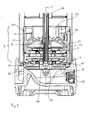
- the centrifugal pump unit described by way of example has a total of eight stages, ie eight wheels. Of these, two wheels 2 are arranged in a first impeller group 4 and six impellers 6 in a second impeller group 8.
- the first impeller group 4 faces the inlet or suction nozzle 10 of the pump unit.
- the second impeller group 8 is connected downstream of the first impeller group in the flow or conveying direction.
- All wheels 2 and 6 are driven by a common shaft 16.
- the shaft 16 is connected at its shaft end 18 with a motor, not shown here, for example, an electric motor for driving.
- the first impeller group 4 is designed to be self-priming in the manner described below, so that the centrifugal pump via the suction nozzle 10 can suck liquid even if the suction nozzle 10 and an upstream subsequent suction line are not filled with liquid.
- the self-priming effect of the first impeller group 4 is determined by the basis of Fig. 2 achieved embodiment explained in more detail.
- a separating element 20 is arranged on the output side of the second impeller 2 in the flow direction of the first impeller group 4. This is designed so that liquid and air are separated from each other. This happens because the liquid is accelerated radially outward, so that the air exits from the separating element 20 in the central region near the shaft 16 and the liquid in the peripheral region near the peripheral wall 22.
- the liquid emerging from the separating element 20 flows over the circumferential wall 22 at its upper edge and enters a return flow channel 24.
- the return flow channel 24 leads on the outer circumference of the first impeller group 4 back in the direction of the suction nozzle 10.
- the return flow channel leads to the suction mouth 28 of the first impeller 2 in the flow direction of the first impeller group 4.
- a closed liquid circuit on the two wheels. 2 of the separating element 20 is realized back through the return flow channel 24 to the suction mouth 28 of the first impeller 2.
- the seals 30 seal the return channel 24 against the pressure channel 12, so that prevents liquid from the pressure side via the return passage 24 can flow over to the suction side in normal operation.
- a bearing 32 is arranged, which is in contact with the outer circumference of the shaft 16. This also serves to seal the separator 20 with respect to the shaft 16 to prevent air from the separator 20 from flowing back to the impellers 2.
- the seal 34 seals the axial end of the shaft 16 to prevent air from flowing from the pressure side of the pump via the shaft to the suction side.
- the seal 36 also serves to separate the pressure side from the suction side, d. H. to seal the discharge nozzle 14 against the suction nozzle 10.
- a valve 38 is arranged in the return flow channel 24.
- This valve 38 is designed such that when it reaches a predetermined pressure on the output side of the second impeller 2, ie on the output side of the separating element 20 and the reflux channel 24 closes the return flow channel. Ie. after reaching this predetermined pressure, the reflux channel 24 is closed and the liquid flows exclusively to the following wheels 6 of the second impeller group eighth
- Fig. 3 shows a detailed view of the separating element 20.
- the separating element 20 defines between the outer periphery of the peripheral wall 22 and a radially outer annular wall 40, a first portion of the return flow channel 24, which forms an inlet region of the return flow channel 24.
- the second portion of the return flow channel 24 is defined between the outer periphery of the wall 40 and a radially spaced sleeve 42 (see FIG Fig. 2 ) Are defined.
- a plurality of holes 44 are formed, which allow the passage from the inlet region of the return flow channel 24 in the second portion of the return flow channel 24 between the wall 40 and the sleeve 42.
- valve elements in the form of spring plates 46 are arranged. These spring plates 46 can take two positions, namely once an open position, which in Fig. 3 designated by the reference numeral 46 '. In this position, the spring plate 46 'extends chord-shaped to the inner circumference of the wall 40 and is thus spaced from the opening 44, so that it is released. Now increases the pressure in the region of the return flow channel 24 which is located between the peripheral wall 22 and the wall 40, the spring plate 46 'is pressed radially outward and abuts against the inside of the wall 40 via the opening 44, so that the Opening 44 is closed.
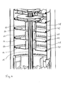
- liquid storage 48 are arranged between the first impeller group 4 and the second impeller group. These are in detail in Fig. 4 shown.
- the liquid reservoirs 48 are formed as annular or toroidal pots which surround the shaft 16.
- the shaft 16 extends through a central opening 50 of the liquid reservoir 48, wherein the wall of the opening 50 is radially spaced from the outer periphery of the shaft 16.
- the opening 50 also serves as a flow path for the conveyed liquid from the first impeller group 4 to the second impeller group 8.
- the peripheral walls 52 of the openings 50 have in the direction of the longitudinal axis X a length which is shorter than the axial length of the outer walls of the liquid storage 48.
- the liquid reservoirs 48 are opened at their upper side, so that liquid which flows through the openings 50 can flow over the peripheral walls 52 into the interior of the liquid reservoirs 48.
- the liquid reservoirs 48 are filled.
- Each liquid reservoir 48 has on its underside an outlet opening 54 with a small diameter.
- the outlet openings 54 are radially spaced from the longitudinal axis X so far that they lie above the free space between the peripheral wall 22 and the wall 40 of the separating element 20.
- the liquid from the first, ie lower liquid storage 48 runs directly into the return flow channel 24. From the two other liquid reservoirs 48, the liquid first passes through the associated outlet opening 54 into the liquid storage unit 48 located below.
- the liquid from the liquid storage 48 via the small outlet opening 54 runs slowly, even if larger air bubbles or gas bubbles flow through the pump unit, be ensured that in the pump unit is still a sufficient amount of liquid to at least the starting circuit through the first impeller group 4, ie through the return flow channel 24 in the to start up again as described above.
- a check valve or non-return valve 55 is still arranged on or in the suction nozzle 10.
- the check valve 55 is arranged directly in the suction nozzle, but it could also be recognized as a separate component to the suction nozzle 10.
- a certain amount of liquid can always be kept in the pump unit, via which at least the starting circuit in the first impeller group 4 can be put into operation again, in order then to suck in further liquid through the suction port 10. In this way, the entire centrifugal pump unit is self-priming.
- the pump unit is a total modular design, this modular design is based on an axial length grid, which is defined by the axial length of the pump stages formed by the wheels 6. These pump stages each have a circumferential jacket 56, which forms the jacket of the individual stage modules. These stage modules are placed axially one on top of the other.
- the liquid reservoirs 48 have the same axial length as the sheaths 56 of the stage modules of the second impeller group 8.
- a jacket 58 which surrounds the first impeller 2 has the same axial length.
- the separating element 20 has an axial length in the direction of the longitudinal axis X, which corresponds to twice the axial length of the sheaths 56 and 58.
- the entire first impeller group 4 has an axial length which corresponds to three times the length of a step module of the second impeller group 8.
- This uniform length grid favors the modular design, as clamping bands, which hold the individual stage modules in the axial direction, only in different lengths, which through this underlying grids are defined.
- a variety of pumps can be assembled with different numbers of wheels, fluid reservoirs 48 and, if necessary, the first impeller group 4 to ensure the self-priming properties.
Landscapes
- Engineering & Computer Science (AREA)
- Mechanical Engineering (AREA)
- General Engineering & Computer Science (AREA)
- Mining & Mineral Resources (AREA)
- Life Sciences & Earth Sciences (AREA)
- Sustainable Development (AREA)
- Structures Of Non-Positive Displacement Pumps (AREA)
Abstract
Description
- Die Erfindung betrifft ein mehrstufiges Kreiselpumpenaggregat mit zumindest zwei Laufrädern, d. h. ein mindestens zweistufiges Kreiselpumpenaggregat.
- Bei derartigen mehrstufigen Kreiselpumpenaggregaten sind mehrere Laufräder in Förderrichtung hintereinander angeordnet, sodass von Stufe zu Stufe eine weitere Druckerhöhung stattfindet. Problematisch bei diesen Kreiselpumpenaggregaten ist, dass sie bei Inbetriebnahme zunächst entlüftet und mit Flüssigkeit gefüllt werden müssen. Die Kreiselpumpenaggregate sind nicht selbstansaugend. Dies ist bei bestimmten Anwendungsfällen nachteilig, beispielsweise in Feuerlöscheinrichtungen, bei denen nicht eine konstante Füllung mit Flüssigkeit, insbesondere Wasser gewährleistet sein kann. In solchen Einrichtungen ist es wichtig, dass die verwendeten Pumpen selbstansaugend sind.
- Es ist daher Aufgabe der Erfindung, ein mehrstufiges Kreiselpumpenaggregat dahingehend zu verbessern, dass es selbstansaugend ist.
- Das erfindungsgemäße mehrstufige Kreiselpumpenaggregat weißt zumindest zwei Laufräder auf, welche vorzugsweise auf einer gemeinsamen Welle angeordnet sind und über diese von einem Motor, insbesondere einem Elektromotor angetrieben werden.
- Das erfindungsgemäße mehrstufige Kreiselpumpenaggregat ist so aufgebaut, dass es in Strömungsrichtung zwei aufeinanderfolgende Laufradgruppen, d. h. Gruppen von Pumpenstufen aufweist, in denen jeweils zumindest ein Laufrad vorhanden ist. Die in Strömungsrichtung erste Laufradgruppe ist dabei so ausgestaltet, dass sie ein selbstansaugendes Verhalten der Kreiselpumpe ermöglicht. Dazu ist in der ersten Laufradgruppe ein Rückflusskanal vorhanden, welcher die Ausgangsseite der ersten Laufradgruppe mit deren Eingangsseite verbindet. Dieser Rückflusskanal ermöglicht es, dass innerhalb der ersten Laufradgruppe durch deren zumindest ein Laufrad eine Flüssigkeitsströmung durch den Rückflusskanal und durch das Laufrad bewirkt werden kann. D. h. in der ersten Laufradgruppe kann eine begrenzte Flüssigkeitsmenge zirkuliert werden. Diese zirkulierende Flüssigkeitsmenge bewirkt in der ersten Laufradgruppe eine ausreichende Sogwirkung, um weitere Flüssigkeit anzusaugen. So kann das gesamte Kreiselpumpenaggregat selbsttätig Flüssigkeit ansaugen. Es ist lediglich bevorzugt, dass in der ersten Laufradgruppe, insbesondere in dem Rückflusskanal eine begrenzte Flüssigkeitsmenge stets vorhanden ist, um zu gewährleisten, dass die zirkulierende Strömung durch das Laufrad der ersten Laufradgruppe und den Rückflusskanal bei Betriebnahme der Pumpe einsetzen kann.
- Der Rückflusskanal mündet vorzugsweise in den Saugmund einer ersten Stufe der ersten Laufradgruppe. Dadurch wird erreicht, dass die durch den Rückflusskanal fließende Flüssigkeit der Eingangsseite des Laufrades der ersten Stufe wieder zugeführt wird, sodass hier eine zirkulierende Förderströmung erreicht wird.
- Weiter bevorzugt ist in dem Rückflusskanal zumindest ein Ventil zum Verschließen des Rückflusskanals vorhanden. Durch dieses Ventil kann der Rückflusskanal verschlossen werden, wenn die Pumpe ihren normalen Betriebszustand erreicht hat. Im normalen Betriebszustand, wenn das Pumpenaggregat Flüssigkeit fördert, würde ein offener Rückflusskanal und ein ständiger Flüssigkeitsrücklauf den Wirkungsrad des Kreiselpumpenaggregates verschlechtern. Durch Schließen des Ventils kann dies nach dem Hochfahren der Pumpe verhindert werden, sodass die Pumpe dann wie eine herkömmliche mehrstufige Kreiselpumpe arbeitet.
- Bevorzugt ist das Ventil derart ausgestaltet, dass es beim Erreichen eines vorbestimmten Fluiddruckes in dem Rückflusskanal bzw. an der Ausgangsseite der ersten Laufradgruppe den Rückflusskanal verschließt. Das Erreichen des vorbestimmten Fluiddruckes wird als normaler Betriebszustand bzw. ein Betriebszustand, in welchem bereits ein ausreichender Förderstrom beim Ansaugen weiterer Flüssigkeit vorhanden ist, erkannt. Vorzugsweise wird von dem Ventil der Fluiddruck im Rückflusskanal, d. h. an der Ausgangsseite der ersten Laufradgruppe erfasst. Das Ventil ist vorzugsweise als Federelement ausgebildet, wobei es durch Federwirkung gegen den im Rückflusskanal herrschenden Fluiddruck offen gehalten wird. Wenn der Fluiddruck die Federkraft übersteigt, wird das Ventil geschlossen. So kann im Rückflusskanal eine Öffnung vorgesehen sein, vor der in Strömungsrichtung ein Federblech liegt, welches so gekrümmt ist, dass das Blech in seiner Ruhelage von der Öffnung beabstandet ist. Durch erhöhten Fluiddruck kann das Blech gegen seine Federvorspannung so verformt werden, dass es gegen die Öffnung gedrückt wird und diese verschließt.
- Weiter bevorzugt ist die erste Laufradgruppe zumindest zweistufig mit zwei in Strömungsrichtung hintereinander angeordneten Laufrädern ausgebildet. Dabei ist der Rückflusskanal so angeordnet, dass er von der Ausgangsseite des zweiten Laufrades zu der Eingangsseite des ersten Laufrades führt. Durch die zweistufige erste Laufradgruppe kann eine ausreichende Strömung und ein ausreichender Sog durch Fördern der Flüssigkeit im Kreislauf durch den Rückflusskanal erreicht werden, um insgesamt im Saugmund bzw. Saugkanal des Kreiselpumpenaggregates einen ausreichenden Unterdruck zum Ansaugen von Flüssigkeit zu erzeugen.
- Ausgangsseitig der ersten Laufradgruppe ist vorzugsweise ein Trennelement angeordnet, welches zum Trennen von Luft und Flüssigkeit ausgebildet ist. Gerade beim Anlaufen des Pumpenaggregates wenn zunächst nur wenig Flüssigkeit durch den Rückflusskanal gefördert wird, wird das Kreiselpumpenaggregat durch seine Saugleitung auch Luft ansaugen, wobei sich Luft und Flüssigkeit beim Eintritt in das erste Laufrad idealerweise vermischen. Daher ist es zweckmäßig, die Luft von der Flüssigkeit ausgangsseitig der ersten Laufradgruppe zu trennen, um vorzugsweise ausschließlich Flüssigkeit durch den Rücklaufkanal wieder zu der Eingangsseite der ersten Laufradegruppe zurückzuführen. So wird das Trockenlaufen des Rückflusskanals verhindert.
- Daher ist das Trennelement weiter bevorzugt relativ zu dem Rückflusskanal so angeordnet, dass die aus dem Trennelement austretende Flüssigkeit in den Rückflusskanal eintritt. So wird sichergestellt, dass die aus dem Rückflusskanal in die erste Laufradgruppe einströmende Flüssigkeit, wenn sie aus der ersten Laufradgruppe wieder austritt, im Wesentlichen vollständig wieder in den Rücklaufkanal eintritt, um so einen Kreislauf zu erzeugen.
- Eingangsseitig der ersten Laufradgruppe ist vorzugsweise ein Rückschlagventil bzw. ein Rückflussverhinderer angeordnet, welcher verhindert, dass Flüssigkeit aus dem Kreiselpumpenaggregat zurück in eine Saugleitung laufen kann. So wird verhindert, dass das Kreiselpumpenaggregat vollständig trocken laufen kann, es wird vielmehr durch das Rückschlagventil auch bei Außerbetriebnahme des Kreiselpumpenaggregates Flüssigkeit im Inneren des Kreiselpumpenaggregates gehalten, welche das Wideranlaufen und ein erneutes Ansaugen ermöglicht. Das Rückschlagventil kann direkt in das Kreiselpumpenaggregat integriert sein, kann jedoch auch als separates Bauteil an den Saugstutzen des Kreiselpumpenaggregates angesetzt sein.
- Gemäß einer weiteren bevorzugten Ausführungsform ist zwischen der ersten und der zweiten Laufradgruppe zumindest ein Flüssigkeitsspeicher angeordnet. Der Flüssigkeitsspeicher ist so ausgebildet, dass er sich beim normalen Betrieb des Kreiselpumpenaggregates mit Flüssigkeit füllt. Bei Außerbetriebnahme des Kreiselpumpenaggregates oder in dem Fall, dass das Kreiselpumpenaggregat Luftblasen fördern sollte, kann durch die Flüssigkeit im Flüssigkeitsspeicher sichergestellt werden, dass die Förderwirkung des Kreiselpumpenaggregates nicht vollständig aussetzt, sondern dass stets genug Flüssigkeit in dem Kreiselpumpenaggregat vorhanden ist, um ein erneutes Ansaugen von Flüssigkeit durch den Saugstutzen bzw. die Saugleitung des Kreiselpumpenaggregates zu ermöglichen.
- Der Flüssigkeitsspeicher weist vorzugsweise zumindest eine Austrittsöffnung auf, welche derart angeordnet ist, dass sie einer Eintrittsöffnung des Rückflusskanals so gegenüberliegt, dass Flüssigkeit aus dem Flüssigkeitsspeicher in den Rückflusskanal fließen kann. So wird erreicht, dass durch den Flüssigkeitsspeicher zunächst der Rückflusskanal gefüllt wird bzw. dieser gefüllt gehalten wird. Die Flüssigkeit aus dem Rückflusskanal fließt dann zur Eingangsseite des ersten Laufrades der ersten Laufradgruppe und tritt in dieses ein, sodass dieses Laufrad sofort eine Förderwirkung erzielen kann und weitere Flüssigkeit durch die Saugleitung ansaugen kann. Bis Flüssigkeit aus der Saugleitung in das erste Laufrad eintritt, wird dann, wie oben beschrieben, die Flüssigkeit im Rückflusskanal zunächst in der ersten Laufradgruppe im Kreis gefördert.
- Das erfindungsgemäße Kreiselpumpenaggregat ist vorzugsweise so ausgebildet, dass sich die Drehachse der Laufräder vertikal erstreckt. Der vorangehend beschriebene Flüssigkeitsspeicher ist dann vorzugsweise so ausgebildet, dass seine Austrittsöffnung an der Unterseite angeordnet ist, sodass die Flüssigkeit aus dem Flüssigkeitsspeicher schwerkraftbedingt nach unten austreten und in den Rückflusskanal eintreten kann. Befüllt wird der Flüssigkeitsspeicher vorzugsweise von oben über die zu den hinter dem Flüssigkeitsspeicher bzw. oberhalb des Flüssigkeitsspeichers angeordneten Pumpenstufen strömende Flüssigkeit. Der Rückflusskanal weist vorzugsweise eine nach oben hin gerichtete Öffnung auf, sodass die Flüssigkeit aus dem Flüssigkeitsspeicher von oben in diese Öffnung eintreten kann.
- Gemäß einer weiteren bevorzugten Ausführungsform können zumindest zwei Flüssigkeitsspeicher derart angeordnet sein, dass eine Austrittsöffnung des zweiten Flüssigkeitsspeichers in eine Öffnung eines ersten Flüssigkeitsspeichers mündet. So können zwei oder mehr Flüssigkeitsspeicher in Strömungs- bzw. Förderrichtung hintereinander zwischen der ersten Laufradgruppe und der zweiten Laufradgruppe angeordnet sein. Dabei fließt die Flüssigkeit aus dem ersten bzw. unteren Flüssigkeitsspeicher, wie vorangehend beschrieben vorzugsweise in den Rücklaufkanal. Die Flüssigkeit aus dem zweiten bzw. nachfolgenden Flüssigkeitsspeicher fließt zunächst in den ersten Flüssigkeitsspeicher und von diesem dann in den Rücklaufkanal. Entsprechend kann Flüssigkeit aus einem dritten Flüssigkeitsspeicher in den zweiten Flüssigkeitsspeicher übertreten. Alle Flüssigkeitsspeicher weisen vorzugsweise eine Austrittsöffnung an der Unterseite und eine Eintrittsöffnung an der Oberseite auf.
- Besonders bevorzugt ist der zumindest eine Flüssigkeitsspeicher als ringförmiger Topf mit einer offenen Oberseite ausgebildet, welcher eine die Laufräder antreibende Welle umgibt. D. h. der Topf ist ring- bzw. torusförmig und weist in der Mitte eine Öffnung auf, durch welche sich die Welle erstreckt. Die Öffnung dient darüber hinaus als Strömungsweg für die geförderte Flüssigkeit von der ersten Laufradgruppe zu der zweiten Laufradgruppe. Dazu ist in der Öffnung ein die Welle umgehender Freiraum vorgesehen. Der topfförmige Flüssigkeitsspeicher ist an seiner Oberseite offen ausgebildet, sodass die Flüssigkeit, welche durch die zentrale Öffnung strömt über den Rand der Öffnung von oben in den topfförmigen Flüssigkeitsspeicher einlaufen kann. Die beschriebene zumindest eine Austrittsöffnung ist vorzugsweise an der Unterseite ausgebildet. Bei der Anordnung mehrere Flüssigkeitsspeicher sind die Austrittsöffnungen der nachfolgenden Flüssigkeitsspeicher so angeordnet, dass sie oberhalb der Oberseite des jeweils vorangehenden Flüssigkeitsspeichers gelegen sind, sodass die Flüssigkeit aus der Austrittsöffnung in den vorangehenden Flüssigkeitsspeicher läuft. Vom ersten, d. h. untersten Flüssigkeitsspeicher läuft die Flüssigkeit aus der Austrittsöffnung, wie beschrieben, in die Rücklaufleitung. Die Austrittsöffnungen sind in der Größe so dimensioniert, dass sich die Flüssigkeitsspeicher langsam leeren.
- Gemäß einer besonders bevorzugten Ausführungsform sind die einzelnen Laufräder der zweiten Laufradgruppe jeweils in einem Stufenmodul angeordnet, wobei alle Stufenmodule dieselbe axiale Höhe aufweisen, und das zumindest eine Laufrad der ersten Laufradgruppe ist ebenfalls in einem solchen Stufenmodul angeordnet, welches eine axiale Höhe hat, die der axialen Höhe oder einem ganzzahligen Vielfachen der Höhe eines Stufenmoduls der zweiten Laufradgruppe entspricht. Dieser modulare Aufbau mit einem festen Raster der axialen Höhen bzw. Längen der einzelnen Module hat den Vorteil, dass aus den Modulen sehr einfach Kreiselpumpenaggregate unterschiedlicher Leistung, insbesondere unterschiedlicher Förder- und Saughöhen realisiert werden können. Auch lässt sich die erste selbstansaugende Laufradgruppe leicht in herkömmliche mehrstufige Kreiselpumpen integrieren, da die Teile der ersten Laufradgruppe in ihrer axialen Länge dasselbe Raster haben wie die Module der zweiten Laufradgruppe. So können beispielsweise dieselben Spannbänder zum Zusammenhalten der Module verwendet werden, wie sie bei herkömmlichen mehrstufigen Kreiselpumpenaggregaten verwendet werden. So kann die erforderliche Teilevielfalt reduziert werden.
- Weiter bevorzugt weisen ebenfalls die zwischen den beiden Laufradgruppen angeordneten Flüssigkeitsspeicher oder Abstandselemente jeweils eine axiale Höhe auf, welcher der axialen Höhe oder einem ganzzahligen Vielfachen dieser Höhe eines Stufenmoduls der zweiten Laufradgruppe entspricht. So wird auch bezüglich dieser Komponenten erreicht, dass die axiale Höhe in das vorhandene Raster der axialen Höhe der einzelnen Pumpenstufen, welche in der zweiten Laufradgruppe angeordnet sind, passt.
- Nachfolgend wird die Erfindung beispielhaft anhand der beigefügten Figuren beschreiben. In diesen zeigt:
- Fig. 1
- eine Schnittansicht eines erfindungsgemäßen Pumpen-aggregates,
- Fig. 2
- eine Detailansicht der ersten Laufradgruppe des Pum-penaggregates gemäß
Fig. 1 , - Fig. 3
- in einer teilweise geschnittenen Detailansicht ein Ventil im Rücklaufkanal und
- Fig. 4
- in einer Schnittansicht die Flüssigkeitsspeicher des Pum-penaggregates gemäß
Fig. 1 . - Das beispielhaft beschriebene Kreiselpumpenaggregat weit insgesamt acht Stufen, d. h. acht Laufräder auf. Von denen sind zwei Laufräder 2 in einer ersten Laufradgruppe 4 und sechs Laufräder 6 in einer zweiten Laufradgruppe 8 angeordnet. Die erste Laufradgruppe 4 ist dem Einlass- bzw. Saugstutzen 10 des Pumpenaggregates zugewandt. Die zweite Laufradgruppe 8 ist der ersten Laufradgruppe in strömungs- bzw. Förderrichtung nachgeschaltet. Wie bei bekannten mehrstufigen Kreiselpumpenaggregaten durchströmt die zu fördernde Flüssigkeit nacheinander die einzelnen Laufräder und wird ausgangsseitig des einander die einzelnen Laufräder und wird ausgangsseitig des letzten Laufrades 6 über den ringförmigen Druckkanal 12 dem Druckstutzen 14 zugeführt. Alle Laufräder 2 und 6 werden über eine gemeinsame Welle 16 angetrieben. Die Welle 16 wird an ihrem Wellenende 18 mit einem hier nicht gezeigten Motor, beispielsweise einem Elektromotor zum Antrieb verbunden.
- Die erste Laufradgruppe 4 ist in der nachfolgend beschriebenen Weise selbstansaugend ausgebildet, sodass die Kreiselpumpe über den Saugstutzen 10 Flüssigkeit auch dann ansaugen kann, wenn der Saugstutzen 10 und eine sich stromaufwärts anschließende Saugleitung nicht mit Flüssigkeit gefüllt sind.
- Die selbstansaugende Wirkung der ersten Laufradgruppe 4 wird durch die anhand von
Fig. 2 näher erläuterte Ausgestaltung erreicht. Ausgangsseitig des in Strömungsrichtung zweiten Laufrades 2 der ersten Laufradgruppe 4 ist ein Trennelement 20 angeordnet. Dieses ist so ausgebildet, dass Flüssigkeit und Luft voneinander getrennt werden. Dies geschieht dadurch, dass die Flüssigkeit radial nach außen beschleunigt wird, sodass aus dem Trennelement 20 die Luft im Zentralbereich nahe der Welle 16 und die Flüssigkeit im Umfangsbereich nahe der Umfangswandung 22 austritt. Die aus dem Trennelement 20 austretende Flüssigkeit überströmt die Umfangswandung 22 an ihrer Oberkante und tritt in einen Rückflusskanal 24 ein. Der Rückflusskanal 24 führt am Außenumfang der ersten Laufradgruppe 4 zurück in Richtung des Saugstutzens 10. Über Öffnungen 26 in einer Bodenplatte führt der Rückflusskanal zum Saugmund 28 des in Strömungsrichtung ersten Laufrades 2 der ersten Laufradgruppe 4. So wird ein geschlossener Flüssigkeitskreislauf über die beiden Laufräder 2 des Trennelement 20 zurück durch den Rückflusskanal 24 zum Saugmund 28 des ersten Laufrades 2 realisiert. - Zum Starten der Pumpe reicht eine geringe Flüssigkeitsmenge, um den beschriebenen Kreislauf durch die beiden Laufräder 2 und den Rückflusskanal 24 in Betrieb zu nehmen. Dadurch erzeugen die Laufräder 2 einen Unterdruck, durch welchen dann durch den Saugstutzen 10 weitere Flüssigkeit angesaugt werden kann. Bei der Erstinbetriebnahme des Pumpenaggregates ist es erforderlich, dass Pumpenaggregat wie herkömmliche Kreiselpumpenaggregate zu entlüften, d. h. mit einer gewissen Flüssigkeitsmenge zu füllen.
- Um den beschriebenen Kreislauf über die Rückflussleitung 24 aufrechterhalten zu können, ist es wichtig, dass die Pumpe im Bereich der ersten Laufradgruppe 4 möglichst luftdicht ausgebildet ist. Hierzu sind verschiedene Dichtungen angeordnet. Die Dichtungen 30 dichten den Rücklaufkanal 24 gegen den Druckkanal 12 ab, sodass verhindert wird, dass Flüssigkeit von der Druckseite über den Rücklaufkanal 24 im normalen Betrieb zur Saugseite überströmen kann. Im Inneren des Trennelementes 20 ist ein Lager 32 angeordnet, welches mit dem Außenumfang der Welle 16 in Kontakt ist. Dieses dient gleichzeitig der Abdichtung des Trennelementes 20 gegenüber der Welle 16, um zu verhindern, dass Luft aus dem Trennelement 20 zurück zu den Laufrädern 2 strömen kann. Die Dichtung 34 dichtet das axiale Ende der Welle 16 ab, um zu verhindern, dass Luft von der Druckseite der Pumpe über die Welle zur Saugseite strömt. Die Dichtung 36 dient ebenfalls dazu, die Druckseite von der Saugseite zu trennen, d. h. den Druckstutzen 14 gegenüber dem Saugstutzen 10 abzudichten.
- Um nach Erreichen des normalen Betriebszustandes, in dem Flüssigkeit durch den Saugstutzen 10 angesaugt wird, zu verhindern, dass Flüssigkeit über den Rückflusskanal 24 zurück zur Saugseite strömt, ist in dem Rückflusskanal 24 ein Ventil 38 angeordnet. Dieses Ventil 38 ist so ausgebildet, dass es beim Erreichen eines vorbestimmten Druckes ausgangsseitig des zweiten Laufrades 2, d. h. ausgangsseitig des Trennelementes 20 und im Rückflusskanal 24 den Rückflusskanal verschließt. D. h. nach Erreichen dieses vorbestimmten Druckes ist der Rückflusskanal 24 verschlossen und die Flüssigkeit strömt ausschließlich zu den nachfolgenden Laufrädern 6 der zweiten Laufradgruppe 8.
- Die Ausgestaltung des Ventils 38 wird näher anhand von
Fig. 3 erläutert.Fig. 3 zeigt eine Detailansicht des Trennelementes 20. Das Trennelement 20 definiert zwischen dem Außenumfang der Umfangswandung 22 und einer radial weiter außen gelegenen ringförmigen Wandung 40, einen ersten Abschnitt des Rückflusskanals 24, welcher einen Eintrittsbereich des Rückflusskanals 24 bildet. Der zweite Abschnitt des Rückflusskanals 24 wird zwischen dem Außenumfang der Wandung 40 und einer radial beabstandeten Hülse 42 (sieheFig. 2 ) definiert. In der Wandung 40 sind mehrere Löcher 44 ausgebildet, welche den Übertritt von dem Einlassbereich des Rückflusskanals 24 in den zweiten Abschnitt des Rückflusskanals 24 zwischen der Wandung 40 und der Hülse 42 ermöglichen. An den Öffnungen 44 sind Ventilelemente in Form von Federblechen 46 angeordnet. Diese Federbleche 46 können zwei Positionen einnehmen, nämlich einmal eine geöffnete Position, welche inFig. 3 mit dem Bezugszeichen 46' bezeichnet ist. In dieser Position erstreckt sich das Federblech 46' sehnenförmig zum Innenumfang der Wandung 40 und ist somit beabstandet von der Öffnung 44, sodass diese freigegeben ist. Steigt nun der Druck in dem Bereich des Rückflusskanals 24, welcher zwischen der Umfangswandung 22 und der Wandung 40 gelegen ist an, wird das Federblech 46' radial nach außen gedrückt und legt sich an die Innenseite der Wandung 40 über der Öffnung 44 an, sodass die Öffnung 44 verschlossen wird. - Um den sicheren Betrieb des Kreiselpumpenaggregates auch dann zu gewährleisten, wenn größere Luftblasen das System passieren, sind zwischen der ersten Laufradgruppe 4 und der zweiten Laufradgruppe 8 drei Flüssigkeitsspeicher 48 angeordnet. Diese sind im Detail in
Fig. 4 gezeigt. Die Flüssigkeitsspeicher 48 sind als ring- bzw. torusförmige Töpfe ausgebildet, welche die Welle 16 umgeben. Die Welle 16 erstreckt sich durch eine zentrale Öffnung 50 der Flüssigkeitsspeicher 48, wobei die Wandung der Öffnung 50 radial vom Außenumfang der Welle 16 beabstandet ist. So dient die Öffnung 50 auch als Strömungsweg für die geförderte Flüssigkeit von der ersten Laufradgruppe 4 zu der zweiten Laufradgruppe 8. Die Umfangswandungen 52 der Öffnungen 50 haben dabei in Richtung der Längsachse X eine Länge, welche kürzer ist als die axiale Länge der Außenwandungen der Flüssigkeitsspeicher 48. So sind die Flüssigkeitsspeicher 48 an ihrer Oberseite geöffnet, sodass Flüssigkeit, welche durch die Öffnungen 50 strömt über die Umfangswandungen 52 hinüber in das Innere der Flüssigkeitsspeicher 48 strömen kann. So werden die Flüssigkeitsspeicher 48 im normalen Betrieb des Pumpenaggregates, wenn Flüssigkeit von der ersten Laufradgruppe 4 zu der zweiten Laufradgruppe 8 strömt, gefüllt. - Jeder Flüssigkeitsspeicher 48 weist an seiner Unterseite eine Auslassöffnung 54 mit kleinem Durchmesser auf. Die Auslassöffnungen 54 sind von der Längsachse X soweit radial beabstandet, dass sie oberhalb des Freiraums zwischen der Umfangswandung 22 und der Wandung 40 des Trennelementes 20 liegen. So läuft die Flüssigkeit aus dem ersten, d. h. unterem Flüssigkeitsspeicher 48 direkt in den Rückflusskanal 24. Aus den beiden anderen Flüssigkeitsspeichern 48 läuft die Flüssigkeit über die zugehörigen Auslassöffnung 54 zunächst in den darunter gelegenen Flüssigkeitsspeicher 48. Dadurch, dass die Flüssigkeit aus den Flüssigkeitsspeichern 48 über die kleine Auslassöffnung 54 langsam abläuft, kann auch dann, wenn größere Luftblasen oder Gasblasen das Pumpenaggregat durchströmen, sichergestellt werden, dass im Pumpenaggregat noch eine ausreichende Flüssigkeitsmenge vorhanden ist, um zumindest den Startkreislauf durch die erste Laufradgruppe 4, d. h. durch den Rückflusskanal 24 in der oben beschriebenen Weise wieder in Betrieb zu nehmen.
- Neben diesen Maßnahmen ist am oder im Saugstutzen 10 noch ein Rückschlagventil bzw. Rückflussverhinderer 55 angeordnet. Hier ist das Rückschlagventil 55 direkt im Saugstutzen angeordnet, es könnte jedoch auch als separates Bauteil an den Saugstutzen 10 angesetzt werden. Über einen solchen kann verhindert werden, dass wenn die sich an den Saugstutzen 10 anschließende Saugleitung trockenläuft, die Flüssigkeit aus dem Pumpenaggregat durch den Saugstutzen 10 zurück in die Saugleitung läuft. So kann stets eine gewisse Flüssigkeitsmenge in dem Pumpenaggregat gehalten werden, über welche zumindest der Startkreislauf in der ersten Laufradgruppe 4 wieder in Betrieb genommen werden kann, um dann weitere Flüssigkeit durch den Saugstutzen 10 anzusaugen. Auf diese Weise wird das gesamte Kreiselpumpenaggregat selbstansaugend ausgebildet.
- Wie in
Fig. 1 zu erkennen ist, ist das Pumpenaggregat insgesamt modular aufgebaut, wobei diesem modularen Aufbau ein axiales Längenraster zugrunde liegt, welches durch die axiale Länge der von den Laufrädern 6 gebildeten Pumpenstufen definiert ist. Diese Pumpenstufen weisen jeweils einen umfänglichen Mantel 56 auf, welcher den Mantel der einzelnen Stufenmodule bildet. Diese Stufenmodule sind axial aufeinandergesetzt. Die Flüssigkeitsspeicher 48 weisen dieselbe axiale Länge wie die Mäntel 56 der Stufenmodule der zweiten Laufradgruppe 8 auf. Darüber hinaus weist auch ein Mantel 58, welcher das erste Laufrad 2 umgibt, dieselbe axiale Länge auf. Das Trennelement 20 weist eine axiale Länge in Richtung der Längsachse X auf, welche dem Doppelten der axialen Länge der Mäntel 56 und 58 entspricht. So hat die gesamte erste Laufradgruppe 4 eine axiale Länge, welche der dreifachen Länge eines Stufenmoduls der zweiten Laufradgruppe 8 entspricht. Dieses einheitliche Längenraster begünstigt den modularen Aufbau, da Spannbänder, welche die einzelnen Stufenmodule in axialer Richtung zusammenhalten, nur in unterschiedlichen Längen, welche durch dieses zugrundliegende Raster definiert sind, vorgehalten werden müssen. Damit können verschiedenste Pumpen zusammengebaut werden, mit unterschiedlichen Zahlen von Laufrädern, Flüssigkeitsspeichern 48 und ggfs. der ersten Laufradgruppe 4 um die selbstansaugenden Eigenschaften sicherzustellen. -
- 2
- Laufräder
- 4
- Erste Laufradgruppe
- 6
- Laufräder
- 8
- Zweite Laufradgruppe
- 10
- Saugstutzen
- 12
- Druckkanal
- 14
- Druckstutzen
- 16
- Welle
- 18
- Wellenende
- 20
- Trennelement
- 22
- Umfangswandung des Trennelementes
- 24
- Rückflusskanal
- 26
- Öffnungen
- 28
- Saugmund
- 30
- Dichtungen
- 32
- Lager
- 34, 36
- Dichtungen
- 38
- Ventil
- 40
- Wandung
- 42
- Hülse
- 44
- Öffnungen
- 46
- Federblech/Ventil
- 48
- Flüssigkeitsspeicher
- 50
- Öffnung
- 52
- Umfangswandungen
- 54
- Auslassöffnungen
- 55
- Rückschlagventil
- 56, 58
- Mantel
- X
- Längsachse
Claims (14)
- Mehrstufiges Kreiselpumpenaggregat mit zumindest zwei Laufrädern (2, 6), dadurch gekennzeichnet, dass
zwei in Strömungsrichtung aufeinanderfolgende Laufradgruppen (4, 8) mit jeweils zumindest einem Laufrad (2, 6) vorhanden sind, wobei in einer ersten Laufradgruppe (4) ein Rückflusskanal (24) vorhanden ist, welcher die Ausgangsseite der ersten Laufradgruppe (4) mit deren Eingangsseite verbindet. - Mehrstufiges Kreiselpumpenaggregat nach Anspruch 1, dadurch gekennzeichnet, dass der Rückflusskanal (24) in den Saugmund (28) einer ersten Stufe der ersten Laufradgruppe (4) mündet.
- Mehrstufiges Kreiselpumpenaggregat nach Anspruch 1 oder 2, dadurch gekennzeichnet, dass in dem Rückflusskanal (24) zumindest ein Ventil (38) zum Verschließen des Rückflusskanals (24) vorhanden ist.
- Mehrstufiges Kreiselpumpenaggregat nach Anspruch 3, dadurch gekennzeichnet, dass das Ventil (38) derart ausgestaltet ist, dass es beim Erreichen eines vorbestimmten Fluiddruckes in dem Rückflusskanal (24) diesen verschließt.
- Mehrstufiges Kreiselpumpenaggregat nach einem der vorangehenden Ansprüche, dadurch gekennzeichnet, dass die erste Laufradgruppe (4) zumindest zweistufig mit zwei in Strömungsrichtung hintereinander angeordneten Laufrädern (2) ausgebildet ist.
- Mehrstufiges Kreiselpumpenaggregat nach einem der vorangehenden Ansprüche, dadurch gekennzeichnet, dass die erste Laufradgruppe (4) an ihrer Ausgangseite ein Trennelement (20) aufweist, welchen zum Trennen von Luft und Flüssigkeit ausgebildet ist.
- Mehrstufiges Kreiselpumpenaggregat nach Anspruch 6, dadurch gekennzeichnet, dass das Trennelement (20) relativ zu dem Rückflusskanal (24) so angeordnet ist, dass die aus dem Trennelement (20) austretende Flüssigkeit in den Rückflusskanal (24) eintritt.
- Mehrstufiges Kreiselpumpenaggregat nach einem der vorangehenden Ansprüche, dadurch gekennzeichnet, dass eingangsseitig der ersten Laufradgruppe (4) ein Rückschlagventil angeordnet ist.
- Mehrstufiges Kreiselpumpenaggregat nach einem der vorangehenden Ansprüche, dadurch gekennzeichnet, dass zwischen der ersten (4) und der zweiten Laufradgruppe (8) zumindest ein Flüssigkeitsspeicher (48) angeordnet ist.
- Mehrstufiges Kreiselpumpenaggregat nach Anspruch 9, dadurch gekennzeichnet, dass der Flüssigkeitsspeicher (48) zumindest eine Austrittsöffnung aufweist, welche derart angeordnet ist, dass sie einer Eintrittsöffnung des Rückflusskanals (24) derart gegenüberliegt, dass Flüssigkeit aus dem Flüssigkeitsspeicher (48) in den Rückflusskanal (24) fließen kann.
- Mehrstufiges Kreiselpumpenaggregat nach Anspruch 9 oder 10, dadurch gekennzeichnet, dass zumindest zwei Flüssigkeitsspeicher (48) derart angeordnet ist, dass eine Austrittsöffnung eines zweiten Flüssigkeitsspeicher (48) in eine Öffnung eines ersten Flüssigkeitsspeichers (48) mündet.
- Mehrstufiges Kreiselpumpenaggregat nach einem der Ansprüche 9 bis 11, dadurch gekennzeichnet, dass der zumindest eine Flüssigkeitsspeicher (48) als ringförmiger Topf mit einer offenen Oberseite ausgebildet ist, welcher eine die Laufräder (2, 6) antreibende Welle (16) umgibt.
- Mehrstufiges Kreiselpumpenaggregat nach einem der vorangehenden Ansprüche, dadurch gekennzeichnet, dass die einzelnen Laufräder (6) der zweiten Laufradgruppe (8) jeweils in einem Stufenmodul angeordnet sind, wobei alle Stufenmodule dieselbe axiale Höhe aufweisen, und das zumindest eine Laufrad (2) der ersten Laufradgruppe (4) in einem Stufenmodul angeordnet ist, welches eine axiale Höhe hat, die der axialen Höhe oder einem ganzzahligen Vielfachen dieser Höhe eines Stufenmoduls der zweiten Laufradgruppe (8) entspricht.
- Mehrstufiges Kreiselpumpenaggregat nach Anspruch 13, dadurch gekennzeichnet, dass zwischen den beiden Laufradgruppen (4, 8) angeordneten Flüssigkeitsspeicher (48) oder Abstandselemente jeweils eine axiale Höhe aufweisen, welche der axialen Höhe oder einem ganzzahligen Vielfachen dieser Höhe eines Stufenmoduls der zweiten Laufradgruppe (8) entspricht.
Priority Applications (7)
| Application Number | Priority Date | Filing Date | Title |
|---|---|---|---|
| EP11002578.0A EP2505842B1 (de) | 2011-03-29 | 2011-03-29 | Mehrstufiges kreiselpumpenaggregat |
| IN817DE2012 IN2012DE00817A (de) | 2011-03-29 | 2012-03-21 | |
| AU2012201654A AU2012201654B2 (en) | 2011-03-29 | 2012-03-21 | Centrifugal radial pumps and method for manufacturing thereof |
| RU2012112043/06A RU2578778C2 (ru) | 2011-03-29 | 2012-03-28 | Многоступенчатый центробежный насосный агрегат |
| CN201910559567.5A CN110307166A (zh) | 2011-03-29 | 2012-03-29 | 多级离心泵机组 |
| CN2012100942511A CN102734176A (zh) | 2011-03-29 | 2012-03-29 | 多级离心泵机组 |
| US13/433,398 US9879680B2 (en) | 2011-03-29 | 2012-03-29 | Multi-stage centrifugal pump unit |
Applications Claiming Priority (1)
| Application Number | Priority Date | Filing Date | Title |
|---|---|---|---|
| EP11002578.0A EP2505842B1 (de) | 2011-03-29 | 2011-03-29 | Mehrstufiges kreiselpumpenaggregat |
Publications (2)
| Publication Number | Publication Date |
|---|---|
| EP2505842A1 true EP2505842A1 (de) | 2012-10-03 |
| EP2505842B1 EP2505842B1 (de) | 2019-12-25 |
Family
ID=44515211
Family Applications (1)
| Application Number | Title | Priority Date | Filing Date |
|---|---|---|---|
| EP11002578.0A Revoked EP2505842B1 (de) | 2011-03-29 | 2011-03-29 | Mehrstufiges kreiselpumpenaggregat |
Country Status (6)
| Country | Link |
|---|---|
| US (1) | US9879680B2 (de) |
| EP (1) | EP2505842B1 (de) |
| CN (2) | CN102734176A (de) |
| AU (1) | AU2012201654B2 (de) |
| IN (1) | IN2012DE00817A (de) |
| RU (1) | RU2578778C2 (de) |
Cited By (4)
| Publication number | Priority date | Publication date | Assignee | Title |
|---|---|---|---|---|
| WO2014187648A1 (de) | 2013-05-22 | 2014-11-27 | Grundfos Holding A/S | Mehrstufiges selbstansaugendes kreiselpumpenaggregat |
| CN107448423A (zh) * | 2016-05-31 | 2017-12-08 | 埃贝斯佩歇气候控制系统有限责任两合公司 | 特别是用于车辆取暖设备的侧通道鼓风机 |
| CN108953158A (zh) * | 2018-09-20 | 2018-12-07 | 浙江南元泵业有限公司 | 多出口离心泵 |
| CN112112840A (zh) * | 2020-09-11 | 2020-12-22 | 台州沃乐农泵业有限公司 | 一种家具厂风机过滤防护组件 |
Families Citing this family (10)
| Publication number | Priority date | Publication date | Assignee | Title |
|---|---|---|---|---|
| EP2607703B1 (de) * | 2011-12-22 | 2014-06-18 | Grundfos Holding A/S | Kreiselpumpe |
| DE102014214805A1 (de) * | 2014-07-29 | 2016-02-04 | Ksb Aktiengesellschaft | Mantelgehäusepumpe |
| EP3244066B1 (de) * | 2016-05-12 | 2020-11-18 | Grundfos Holding A/S | Zentrifugalpumpe |
| EP3293397B1 (de) * | 2016-09-13 | 2018-10-24 | Grundfos Holding A/S | Kreiselpumpenaggregat und verfahren zum entlüften |
| WO2018058097A1 (en) | 2016-09-26 | 2018-03-29 | Fluid Handling Llc | Multi-stage impeller produced via additive manufacturing |
| EP3343054A1 (de) | 2016-12-28 | 2018-07-04 | Grundfos Holding A/S | Lagerkäfig für mehrstufige kreiselpumpe |
| US11560902B2 (en) * | 2019-01-25 | 2023-01-24 | Pentair Flow Technologies, Llc | Self-priming assembly for use in a multi-stage pump |
| CN111594451A (zh) * | 2020-05-29 | 2020-08-28 | 广东凌霄泵业股份有限公司 | 卧式自吸泵 |
| EP3929445A1 (de) * | 2020-06-22 | 2021-12-29 | Grundfos Holding A/S | Zentrifugalpumpenvorrichtung |
| CN117823415B (zh) * | 2024-03-04 | 2024-05-03 | 山东华立供水设备有限公司 | 一种多级离心泵 |
Citations (3)
| Publication number | Priority date | Publication date | Assignee | Title |
|---|---|---|---|---|
| DE2249883A1 (de) * | 1971-10-15 | 1973-05-30 | Novex Co Ltd | Selbstansaugende kreiselpumpe |
| EP0406787A2 (de) * | 1989-07-05 | 1991-01-09 | Ebara Corporation | Gehäuse, insbesondere für Radialkreiselpumpen und Verfahren zu dessen Herstellung |
| US5513959A (en) * | 1992-01-14 | 1996-05-07 | Ksb S.A. | Valve for pump with priming circuit |
Family Cites Families (24)
| Publication number | Priority date | Publication date | Assignee | Title |
|---|---|---|---|---|
| DE610778C (de) | 1933-11-24 | 1935-03-16 | Carl Metz Feuerwehrgeraetefabr | Selbstansaugende mehrstufige Kreiselpumpe |
| FR936832A (fr) * | 1945-02-03 | 1948-07-30 | Pompe centrifuge multiple à rotors montés en série avec auto-amorçage | |
| GB674815A (en) * | 1950-05-15 | 1952-07-02 | Schulz Wilhelm | Improvements relating to centrifugal pumps |
| GB732293A (en) | 1952-05-12 | 1955-06-22 | Jacuzzi Brothers Inc | Improvements in or relating to self-priming pump systems, particularly for deep wells |
| CH484369A (de) * | 1967-07-07 | 1970-01-15 | Muanyagipari Ki | Ein- oder mehrstufige selbstansaugende Pumpe |
| FR2044994A5 (de) | 1969-05-29 | 1971-02-26 | Guinard Pompes | |
| FR2342416A1 (fr) | 1976-02-27 | 1977-09-23 | Materiel Telephonique | Pompe centrifuge multicellulaire auto-amorcante |
| DE3130832C2 (de) | 1980-08-05 | 1986-05-22 | Sihi Gmbh & Co Kg, 2210 Itzehoe | Selbstansaugende Kreiselpumpe, insbesondere zur Förderung von Flüssigkeiten in der Nähe ihres Siedepunktes |
| JPS58143189A (ja) | 1982-02-19 | 1983-08-25 | Fuji Electric Co Ltd | ポンプユニツトにおけるポンプ起動装置 |
| US4780050A (en) * | 1985-12-23 | 1988-10-25 | Sundstrand Corporation | Self-priming pump system |
| US4872808A (en) * | 1987-06-22 | 1989-10-10 | Oil Dynamics, Inc. | Centrifugal pump modular bearing support for pumping fluids containing abrasive particles |
| IT1257704B (it) | 1991-12-05 | 1996-02-01 | Nocchi Pompe Spa | Pompa per acqua plurifunzionale: centrifuga, per aspirazione profonda,autoadescante, centrifuga con regolazione di pressione, autoadescante con regolazione di pressione, con dispositivo di avviamento e/0 arresto automatico |
| CN2217126Y (zh) * | 1994-01-14 | 1996-01-10 | 仪群 | 便拆式自吸管道泵 |
| DE4415157A1 (de) * | 1994-05-02 | 1995-11-09 | Klein Schanzlin & Becker Ag | Selbstansaugende mehrstufige Kreiselpumpe |
| ES2115486B1 (es) | 1994-12-20 | 1999-02-16 | Bogemar Sl | Electrobomba centrifuga multicelular. |
| JPH09195969A (ja) * | 1996-01-17 | 1997-07-29 | Shin Meiwa Ind Co Ltd | 自吸式ポンプにおける呼び水循環装置 |
| CN2471976Y (zh) | 2001-03-19 | 2002-01-16 | 佛山柴油机厂有限公司 | 壳体一体式多级自吸离心泵 |
| DE10239997A1 (de) | 2002-08-27 | 2004-03-04 | Gardena Manufacturing Gmbh | Pumpenanordnung |
| US8128340B2 (en) * | 2004-03-08 | 2012-03-06 | Gorman-Rupp, Co. | Stacked self-priming pump and centrifugal pump |
| CN2744859Y (zh) * | 2004-11-01 | 2005-12-07 | 义乌市第二石油化工泵厂 | 强力气液分离导叶式多级自吸离心泵 |
| CN100455815C (zh) | 2005-01-30 | 2009-01-28 | 陆雄 | 动态调控叶轮对称布置的多级离心泵轴向力的方法 |
| DE602005001620D1 (de) | 2005-05-31 | 2007-08-23 | Pedrollo Spa | Kreiselpumpe |
| WO2008036098A2 (en) * | 2006-09-21 | 2008-03-27 | The Gorman-Rupp Company | Improved self-priming centrifugal pump |
| CN201610847U (zh) | 2009-11-30 | 2010-10-20 | 镇江正汉泵业有限公司 | 一种提高自吸能力的立式自吸泵 |
-
2011
- 2011-03-29 EP EP11002578.0A patent/EP2505842B1/de not_active Revoked
-
2012
- 2012-03-21 AU AU2012201654A patent/AU2012201654B2/en not_active Ceased
- 2012-03-21 IN IN817DE2012 patent/IN2012DE00817A/en unknown
- 2012-03-28 RU RU2012112043/06A patent/RU2578778C2/ru not_active IP Right Cessation
- 2012-03-29 CN CN2012100942511A patent/CN102734176A/zh active Pending
- 2012-03-29 US US13/433,398 patent/US9879680B2/en not_active Expired - Fee Related
- 2012-03-29 CN CN201910559567.5A patent/CN110307166A/zh active Pending
Patent Citations (3)
| Publication number | Priority date | Publication date | Assignee | Title |
|---|---|---|---|---|
| DE2249883A1 (de) * | 1971-10-15 | 1973-05-30 | Novex Co Ltd | Selbstansaugende kreiselpumpe |
| EP0406787A2 (de) * | 1989-07-05 | 1991-01-09 | Ebara Corporation | Gehäuse, insbesondere für Radialkreiselpumpen und Verfahren zu dessen Herstellung |
| US5513959A (en) * | 1992-01-14 | 1996-05-07 | Ksb S.A. | Valve for pump with priming circuit |
Cited By (9)
| Publication number | Priority date | Publication date | Assignee | Title |
|---|---|---|---|---|
| WO2014187648A1 (de) | 2013-05-22 | 2014-11-27 | Grundfos Holding A/S | Mehrstufiges selbstansaugendes kreiselpumpenaggregat |
| RU2636288C2 (ru) * | 2013-05-22 | 2017-11-21 | Грундфос Холдинг А/С | Многоступенчатый самовсасывающий центробежный насосный агрегат |
| US10337516B2 (en) | 2013-05-22 | 2019-07-02 | Grundfos Holding A/S | Multi-stage, self-priming centrifugal pump assembly |
| CN107448423A (zh) * | 2016-05-31 | 2017-12-08 | 埃贝斯佩歇气候控制系统有限责任两合公司 | 特别是用于车辆取暖设备的侧通道鼓风机 |
| CN107448423B (zh) * | 2016-05-31 | 2019-10-15 | 埃贝斯佩歇气候控制系统有限责任两合公司 | 侧通道鼓风机 |
| US10527044B2 (en) | 2016-05-31 | 2020-01-07 | Eberspächer Climate Control Systems GmbH & Co. KG | Side channel blower, especially for a vehicle heater |
| CN108953158A (zh) * | 2018-09-20 | 2018-12-07 | 浙江南元泵业有限公司 | 多出口离心泵 |
| CN112112840A (zh) * | 2020-09-11 | 2020-12-22 | 台州沃乐农泵业有限公司 | 一种家具厂风机过滤防护组件 |
| CN112112840B (zh) * | 2020-09-11 | 2022-09-23 | 南通大通宝富风机有限公司 | 一种家具厂风机过滤防护组件 |
Also Published As
| Publication number | Publication date |
|---|---|
| US9879680B2 (en) | 2018-01-30 |
| RU2012112043A (ru) | 2013-10-10 |
| US20120251308A1 (en) | 2012-10-04 |
| CN102734176A (zh) | 2012-10-17 |
| IN2012DE00817A (de) | 2015-08-21 |
| AU2012201654A1 (en) | 2012-10-18 |
| RU2578778C2 (ru) | 2016-03-27 |
| EP2505842B1 (de) | 2019-12-25 |
| CN110307166A (zh) | 2019-10-08 |
| AU2012201654B2 (en) | 2015-08-20 |
Similar Documents
| Publication | Publication Date | Title |
|---|---|---|
| EP2505842B1 (de) | Mehrstufiges kreiselpumpenaggregat | |
| DE69023699T2 (de) | Selbstansaugende Kreiselpumpe. | |
| WO2014187648A1 (de) | Mehrstufiges selbstansaugendes kreiselpumpenaggregat | |
| DE60218820T2 (de) | Selbstansaugendes pumpenaggregat | |
| EP3161320B1 (de) | Seitenkanalpumpe | |
| EP2495444A2 (de) | Pumpe | |
| DE102012210554A1 (de) | Pumpe | |
| DE1528657B2 (de) | Gasabscheider fuer motor-tauchpumpen | |
| WO2016083382A1 (de) | Kreiselpumpe mit einer leiteinrichtung | |
| DE102016123171A1 (de) | Laufrad und Pumpe verwendend das Laufrad | |
| EP3334942A1 (de) | Dunstabzugsvorrichtung mit diagonalventilator | |
| DE3128374A1 (de) | Radialschaufelunterstuetzte seitenkanalpumpe | |
| EP2362101B1 (de) | Dosierpumpe | |
| DE102004022962B4 (de) | Zentrifugallüfter und Gehäuse davon | |
| EP3364043B1 (de) | Pumpenaggregat mit integrierter entlüftung- und entleerungseinheit | |
| DE102016225533B4 (de) | Pumpenanordnung und Nuklearreaktor mit einer solchen Pumpenanordnung | |
| DE102019101277A1 (de) | Axiallüfteranordnung für Fahrzeuge | |
| DE69723488T2 (de) | Seitenkanalpumpe | |
| DE3141080C2 (de) | "Selbstansaugende Kreiselpumpe" | |
| WO2018150247A1 (de) | Pumpenanordnung | |
| DE102005034341A1 (de) | Tauchmotorpumpe mit Kühlmantel | |
| EP2165085B1 (de) | Pumpe für ein haushaltsgerät | |
| DE202009003880U1 (de) | Multi-Inlet-Vakuumpumpe | |
| EP3156663B1 (de) | Kreiselpumpenaggregat | |
| EP2505843A1 (de) | Kreiselpumpenanordnung |
Legal Events
| Date | Code | Title | Description |
|---|---|---|---|
| PUAI | Public reference made under article 153(3) epc to a published international application that has entered the european phase |
Free format text: ORIGINAL CODE: 0009012 |
|
| AK | Designated contracting states |
Kind code of ref document: A1 Designated state(s): AL AT BE BG CH CY CZ DE DK EE ES FI FR GB GR HR HU IE IS IT LI LT LU LV MC MK MT NL NO PL PT RO RS SE SI SK SM TR |
|
| AX | Request for extension of the european patent |
Extension state: BA ME |
|
| 17P | Request for examination filed |
Effective date: 20130302 |
|
| STAA | Information on the status of an ep patent application or granted ep patent |
Free format text: STATUS: EXAMINATION IS IN PROGRESS |
|
| 17Q | First examination report despatched |
Effective date: 20180102 |
|
| GRAP | Despatch of communication of intention to grant a patent |
Free format text: ORIGINAL CODE: EPIDOSNIGR1 |
|
| STAA | Information on the status of an ep patent application or granted ep patent |
Free format text: STATUS: GRANT OF PATENT IS INTENDED |
|
| INTG | Intention to grant announced |
Effective date: 20190819 |
|
| GRAS | Grant fee paid |
Free format text: ORIGINAL CODE: EPIDOSNIGR3 |
|
| GRAA | (expected) grant |
Free format text: ORIGINAL CODE: 0009210 |
|
| STAA | Information on the status of an ep patent application or granted ep patent |
Free format text: STATUS: THE PATENT HAS BEEN GRANTED |
|
| AK | Designated contracting states |
Kind code of ref document: B1 Designated state(s): AL AT BE BG CH CY CZ DE DK EE ES FI FR GB GR HR HU IE IS IT LI LT LU LV MC MK MT NL NO PL PT RO RS SE SI SK SM TR |
|
| REG | Reference to a national code |
Ref country code: GB Ref legal event code: FG4D Free format text: NOT ENGLISH |
|
| REG | Reference to a national code |
Ref country code: CH Ref legal event code: EP |
|
| REG | Reference to a national code |
Ref country code: DE Ref legal event code: R096 Ref document number: 502011016344 Country of ref document: DE |
|
| REG | Reference to a national code |
Ref country code: AT Ref legal event code: REF Ref document number: 1217417 Country of ref document: AT Kind code of ref document: T Effective date: 20200115 |
|
| REG | Reference to a national code |
Ref country code: IE Ref legal event code: FG4D Free format text: LANGUAGE OF EP DOCUMENT: GERMAN |
|
| REG | Reference to a national code |
Ref country code: NL Ref legal event code: MP Effective date: 20191225 |
|
| PG25 | Lapsed in a contracting state [announced via postgrant information from national office to epo] |
Ref country code: SE Free format text: LAPSE BECAUSE OF FAILURE TO SUBMIT A TRANSLATION OF THE DESCRIPTION OR TO PAY THE FEE WITHIN THE PRESCRIBED TIME-LIMIT Effective date: 20191225 Ref country code: LV Free format text: LAPSE BECAUSE OF FAILURE TO SUBMIT A TRANSLATION OF THE DESCRIPTION OR TO PAY THE FEE WITHIN THE PRESCRIBED TIME-LIMIT Effective date: 20191225 Ref country code: LT Free format text: LAPSE BECAUSE OF FAILURE TO SUBMIT A TRANSLATION OF THE DESCRIPTION OR TO PAY THE FEE WITHIN THE PRESCRIBED TIME-LIMIT Effective date: 20191225 Ref country code: GR Free format text: LAPSE BECAUSE OF FAILURE TO SUBMIT A TRANSLATION OF THE DESCRIPTION OR TO PAY THE FEE WITHIN THE PRESCRIBED TIME-LIMIT Effective date: 20200326 Ref country code: FI Free format text: LAPSE BECAUSE OF FAILURE TO SUBMIT A TRANSLATION OF THE DESCRIPTION OR TO PAY THE FEE WITHIN THE PRESCRIBED TIME-LIMIT Effective date: 20191225 Ref country code: BG Free format text: LAPSE BECAUSE OF FAILURE TO SUBMIT A TRANSLATION OF THE DESCRIPTION OR TO PAY THE FEE WITHIN THE PRESCRIBED TIME-LIMIT Effective date: 20200325 Ref country code: NO Free format text: LAPSE BECAUSE OF FAILURE TO SUBMIT A TRANSLATION OF THE DESCRIPTION OR TO PAY THE FEE WITHIN THE PRESCRIBED TIME-LIMIT Effective date: 20200325 |
|
| PGFP | Annual fee paid to national office [announced via postgrant information from national office to epo] |
Ref country code: DE Payment date: 20200319 Year of fee payment: 10 Ref country code: GB Payment date: 20200325 Year of fee payment: 10 |
|
| REG | Reference to a national code |
Ref country code: LT Ref legal event code: MG4D |
|
| PG25 | Lapsed in a contracting state [announced via postgrant information from national office to epo] |
Ref country code: HR Free format text: LAPSE BECAUSE OF FAILURE TO SUBMIT A TRANSLATION OF THE DESCRIPTION OR TO PAY THE FEE WITHIN THE PRESCRIBED TIME-LIMIT Effective date: 20191225 Ref country code: RS Free format text: LAPSE BECAUSE OF FAILURE TO SUBMIT A TRANSLATION OF THE DESCRIPTION OR TO PAY THE FEE WITHIN THE PRESCRIBED TIME-LIMIT Effective date: 20191225 |
|
| PG25 | Lapsed in a contracting state [announced via postgrant information from national office to epo] |
Ref country code: AL Free format text: LAPSE BECAUSE OF FAILURE TO SUBMIT A TRANSLATION OF THE DESCRIPTION OR TO PAY THE FEE WITHIN THE PRESCRIBED TIME-LIMIT Effective date: 20191225 |
|
| PGFP | Annual fee paid to national office [announced via postgrant information from national office to epo] |
Ref country code: FR Payment date: 20200325 Year of fee payment: 10 |
|
| PG25 | Lapsed in a contracting state [announced via postgrant information from national office to epo] |
Ref country code: PT Free format text: LAPSE BECAUSE OF FAILURE TO SUBMIT A TRANSLATION OF THE DESCRIPTION OR TO PAY THE FEE WITHIN THE PRESCRIBED TIME-LIMIT Effective date: 20200520 Ref country code: EE Free format text: LAPSE BECAUSE OF FAILURE TO SUBMIT A TRANSLATION OF THE DESCRIPTION OR TO PAY THE FEE WITHIN THE PRESCRIBED TIME-LIMIT Effective date: 20191225 Ref country code: CZ Free format text: LAPSE BECAUSE OF FAILURE TO SUBMIT A TRANSLATION OF THE DESCRIPTION OR TO PAY THE FEE WITHIN THE PRESCRIBED TIME-LIMIT Effective date: 20191225 Ref country code: RO Free format text: LAPSE BECAUSE OF FAILURE TO SUBMIT A TRANSLATION OF THE DESCRIPTION OR TO PAY THE FEE WITHIN THE PRESCRIBED TIME-LIMIT Effective date: 20191225 Ref country code: NL Free format text: LAPSE BECAUSE OF FAILURE TO SUBMIT A TRANSLATION OF THE DESCRIPTION OR TO PAY THE FEE WITHIN THE PRESCRIBED TIME-LIMIT Effective date: 20191225 |
|
| PG25 | Lapsed in a contracting state [announced via postgrant information from national office to epo] |
Ref country code: SM Free format text: LAPSE BECAUSE OF FAILURE TO SUBMIT A TRANSLATION OF THE DESCRIPTION OR TO PAY THE FEE WITHIN THE PRESCRIBED TIME-LIMIT Effective date: 20191225 Ref country code: SK Free format text: LAPSE BECAUSE OF FAILURE TO SUBMIT A TRANSLATION OF THE DESCRIPTION OR TO PAY THE FEE WITHIN THE PRESCRIBED TIME-LIMIT Effective date: 20191225 Ref country code: IS Free format text: LAPSE BECAUSE OF FAILURE TO SUBMIT A TRANSLATION OF THE DESCRIPTION OR TO PAY THE FEE WITHIN THE PRESCRIBED TIME-LIMIT Effective date: 20200425 |
|
| PGFP | Annual fee paid to national office [announced via postgrant information from national office to epo] |
Ref country code: IT Payment date: 20200422 Year of fee payment: 10 |
|
| REG | Reference to a national code |
Ref country code: DE Ref legal event code: R026 Ref document number: 502011016344 Country of ref document: DE |
|
| PLBI | Opposition filed |
Free format text: ORIGINAL CODE: 0009260 |
|
| PLAX | Notice of opposition and request to file observation + time limit sent |
Free format text: ORIGINAL CODE: EPIDOSNOBS2 |
|
| PG25 | Lapsed in a contracting state [announced via postgrant information from national office to epo] |
Ref country code: DK Free format text: LAPSE BECAUSE OF FAILURE TO SUBMIT A TRANSLATION OF THE DESCRIPTION OR TO PAY THE FEE WITHIN THE PRESCRIBED TIME-LIMIT Effective date: 20191225 Ref country code: MC Free format text: LAPSE BECAUSE OF FAILURE TO SUBMIT A TRANSLATION OF THE DESCRIPTION OR TO PAY THE FEE WITHIN THE PRESCRIBED TIME-LIMIT Effective date: 20191225 Ref country code: ES Free format text: LAPSE BECAUSE OF FAILURE TO SUBMIT A TRANSLATION OF THE DESCRIPTION OR TO PAY THE FEE WITHIN THE PRESCRIBED TIME-LIMIT Effective date: 20191225 |
|
| REG | Reference to a national code |
Ref country code: CH Ref legal event code: PL |
|
| 26 | Opposition filed |
Opponent name: KSB SE & CO. KGAA Effective date: 20200925 |
|
| PG25 | Lapsed in a contracting state [announced via postgrant information from national office to epo] |
Ref country code: SI Free format text: LAPSE BECAUSE OF FAILURE TO SUBMIT A TRANSLATION OF THE DESCRIPTION OR TO PAY THE FEE WITHIN THE PRESCRIBED TIME-LIMIT Effective date: 20191225 |
|
| REG | Reference to a national code |
Ref country code: BE Ref legal event code: MM Effective date: 20200331 |
|
| PG25 | Lapsed in a contracting state [announced via postgrant information from national office to epo] |
Ref country code: LU Free format text: LAPSE BECAUSE OF NON-PAYMENT OF DUE FEES Effective date: 20200329 |
|
| PG25 | Lapsed in a contracting state [announced via postgrant information from national office to epo] |
Ref country code: CH Free format text: LAPSE BECAUSE OF NON-PAYMENT OF DUE FEES Effective date: 20200331 Ref country code: LI Free format text: LAPSE BECAUSE OF NON-PAYMENT OF DUE FEES Effective date: 20200331 Ref country code: IE Free format text: LAPSE BECAUSE OF NON-PAYMENT OF DUE FEES Effective date: 20200329 |
|
| PLBB | Reply of patent proprietor to notice(s) of opposition received |
Free format text: ORIGINAL CODE: EPIDOSNOBS3 |
|
| PG25 | Lapsed in a contracting state [announced via postgrant information from national office to epo] |
Ref country code: BE Free format text: LAPSE BECAUSE OF NON-PAYMENT OF DUE FEES Effective date: 20200331 Ref country code: PL Free format text: LAPSE BECAUSE OF FAILURE TO SUBMIT A TRANSLATION OF THE DESCRIPTION OR TO PAY THE FEE WITHIN THE PRESCRIBED TIME-LIMIT Effective date: 20191225 |
|
| REG | Reference to a national code |
Ref country code: AT Ref legal event code: MM01 Ref document number: 1217417 Country of ref document: AT Kind code of ref document: T Effective date: 20200329 |
|
| RDAF | Communication despatched that patent is revoked |
Free format text: ORIGINAL CODE: EPIDOSNREV1 |
|
| REG | Reference to a national code |
Ref country code: DE Ref legal event code: R103 Ref document number: 502011016344 Country of ref document: DE Ref country code: DE Ref legal event code: R064 Ref document number: 502011016344 Country of ref document: DE |
|
| PG25 | Lapsed in a contracting state [announced via postgrant information from national office to epo] |
Ref country code: AT Free format text: LAPSE BECAUSE OF NON-PAYMENT OF DUE FEES Effective date: 20200329 |
|
| RDAG | Patent revoked |
Free format text: ORIGINAL CODE: 0009271 |
|
| STAA | Information on the status of an ep patent application or granted ep patent |
Free format text: STATUS: PATENT REVOKED |
|
| REG | Reference to a national code |
Ref country code: CH Ref legal event code: PL |
|
| REG | Reference to a national code |
Ref country code: FI Ref legal event code: MGE |
|
| 27W | Patent revoked |
Effective date: 20210607 |
|
| GBPR | Gb: patent revoked under art. 102 of the ep convention designating the uk as contracting state |
Effective date: 20210607 |
|
| REG | Reference to a national code |
Ref country code: AT Ref legal event code: MA03 Ref document number: 1217417 Country of ref document: AT Kind code of ref document: T Effective date: 20210607 |
|
| PG25 | Lapsed in a contracting state [announced via postgrant information from national office to epo] |
Ref country code: TR Free format text: LAPSE BECAUSE OF FAILURE TO SUBMIT A TRANSLATION OF THE DESCRIPTION OR TO PAY THE FEE WITHIN THE PRESCRIBED TIME-LIMIT Effective date: 20191225 Ref country code: MT Free format text: LAPSE BECAUSE OF FAILURE TO SUBMIT A TRANSLATION OF THE DESCRIPTION OR TO PAY THE FEE WITHIN THE PRESCRIBED TIME-LIMIT Effective date: 20191225 Ref country code: CY Free format text: LAPSE BECAUSE OF FAILURE TO SUBMIT A TRANSLATION OF THE DESCRIPTION OR TO PAY THE FEE WITHIN THE PRESCRIBED TIME-LIMIT Effective date: 20191225 |
|
| PG25 | Lapsed in a contracting state [announced via postgrant information from national office to epo] |
Ref country code: MK Free format text: LAPSE BECAUSE OF FAILURE TO SUBMIT A TRANSLATION OF THE DESCRIPTION OR TO PAY THE FEE WITHIN THE PRESCRIBED TIME-LIMIT Effective date: 20191225 |
|
| PG25 | Lapsed in a contracting state [announced via postgrant information from national office to epo] |
Ref country code: FR Free format text: LAPSE BECAUSE OF NON-PAYMENT OF DUE FEES Effective date: 20210331 |
|
| PG25 | Lapsed in a contracting state [announced via postgrant information from national office to epo] |
Ref country code: IT Free format text: LAPSE BECAUSE OF NON-PAYMENT OF DUE FEES Effective date: 20210329 |
|
| PG25 | Lapsed in a contracting state [announced via postgrant information from national office to epo] |
Ref country code: GB Free format text: LAPSE BECAUSE OF NON-PAYMENT OF DUE FEES Effective date: 20210329 |