EP0406787A2 - Gehäuse, insbesondere für Radialkreiselpumpen und Verfahren zu dessen Herstellung - Google Patents
Gehäuse, insbesondere für Radialkreiselpumpen und Verfahren zu dessen Herstellung Download PDFInfo
- Publication number
- EP0406787A2 EP0406787A2 EP90112637A EP90112637A EP0406787A2 EP 0406787 A2 EP0406787 A2 EP 0406787A2 EP 90112637 A EP90112637 A EP 90112637A EP 90112637 A EP90112637 A EP 90112637A EP 0406787 A2 EP0406787 A2 EP 0406787A2
- Authority
- EP
- European Patent Office
- Prior art keywords
- case
- impeller
- stage
- volute
- semi
- Prior art date
- Legal status (The legal status is an assumption and is not a legal conclusion. Google has not performed a legal analysis and makes no representation as to the accuracy of the status listed.)
- Granted
Links
- 238000004519 manufacturing process Methods 0.000 title claims abstract description 14
- 238000000034 method Methods 0.000 title claims abstract description 13
- 239000002184 metal Substances 0.000 claims abstract description 8
- 239000007788 liquid Substances 0.000 claims description 8
- 230000015572 biosynthetic process Effects 0.000 claims description 6
- 238000005755 formation reaction Methods 0.000 claims description 6
- 230000008878 coupling Effects 0.000 claims 1
- 238000010168 coupling process Methods 0.000 claims 1
- 238000005859 coupling reaction Methods 0.000 claims 1
- 230000014759 maintenance of location Effects 0.000 claims 1
- 238000011144 upstream manufacturing Methods 0.000 claims 1
- 238000009792 diffusion process Methods 0.000 description 6
- 238000003780 insertion Methods 0.000 description 3
- 230000037431 insertion Effects 0.000 description 3
- 239000000463 material Substances 0.000 description 3
- 239000012530 fluid Substances 0.000 description 2
- 230000002093 peripheral effect Effects 0.000 description 2
- 230000002860 competitive effect Effects 0.000 description 1
- 238000007599 discharging Methods 0.000 description 1
- 238000000605 extraction Methods 0.000 description 1
- 230000000670 limiting effect Effects 0.000 description 1
- 238000003754 machining Methods 0.000 description 1
- 238000012986 modification Methods 0.000 description 1
- 230000004048 modification Effects 0.000 description 1
- 238000009931 pascalization Methods 0.000 description 1
- 238000007789 sealing Methods 0.000 description 1
- 238000000926 separation method Methods 0.000 description 1
- 229910001220 stainless steel Inorganic materials 0.000 description 1
- 239000010935 stainless steel Substances 0.000 description 1
Images

Classifications
-
- B—PERFORMING OPERATIONS; TRANSPORTING
- B21—MECHANICAL METAL-WORKING WITHOUT ESSENTIALLY REMOVING MATERIAL; PUNCHING METAL
- B21D—WORKING OR PROCESSING OF SHEET METAL OR METAL TUBES, RODS OR PROFILES WITHOUT ESSENTIALLY REMOVING MATERIAL; PUNCHING METAL
- B21D26/00—Shaping without cutting otherwise than using rigid devices or tools or yieldable or resilient pads, i.e. applying fluid pressure or magnetic forces
- B21D26/02—Shaping without cutting otherwise than using rigid devices or tools or yieldable or resilient pads, i.e. applying fluid pressure or magnetic forces by applying fluid pressure
- B21D26/021—Deforming sheet bodies
-
- B—PERFORMING OPERATIONS; TRANSPORTING
- B21—MECHANICAL METAL-WORKING WITHOUT ESSENTIALLY REMOVING MATERIAL; PUNCHING METAL
- B21D—WORKING OR PROCESSING OF SHEET METAL OR METAL TUBES, RODS OR PROFILES WITHOUT ESSENTIALLY REMOVING MATERIAL; PUNCHING METAL
- B21D26/00—Shaping without cutting otherwise than using rigid devices or tools or yieldable or resilient pads, i.e. applying fluid pressure or magnetic forces
- B21D26/02—Shaping without cutting otherwise than using rigid devices or tools or yieldable or resilient pads, i.e. applying fluid pressure or magnetic forces by applying fluid pressure
-
- F—MECHANICAL ENGINEERING; LIGHTING; HEATING; WEAPONS; BLASTING
- F04—POSITIVE - DISPLACEMENT MACHINES FOR LIQUIDS; PUMPS FOR LIQUIDS OR ELASTIC FLUIDS
- F04D—NON-POSITIVE-DISPLACEMENT PUMPS
- F04D1/00—Radial-flow pumps, e.g. centrifugal pumps; Helico-centrifugal pumps
- F04D1/06—Multi-stage pumps
- F04D1/063—Multi-stage pumps of the vertically split casing type
-
- F—MECHANICAL ENGINEERING; LIGHTING; HEATING; WEAPONS; BLASTING
- F04—POSITIVE - DISPLACEMENT MACHINES FOR LIQUIDS; PUMPS FOR LIQUIDS OR ELASTIC FLUIDS
- F04D—NON-POSITIVE-DISPLACEMENT PUMPS
- F04D29/00—Details, component parts, or accessories
- F04D29/40—Casings; Connections of working fluid
- F04D29/42—Casings; Connections of working fluid for radial or helico-centrifugal pumps
- F04D29/426—Casings; Connections of working fluid for radial or helico-centrifugal pumps especially adapted for liquid pumps
- F04D29/4266—Casings; Connections of working fluid for radial or helico-centrifugal pumps especially adapted for liquid pumps made of sheet metal
-
- F—MECHANICAL ENGINEERING; LIGHTING; HEATING; WEAPONS; BLASTING
- F04—POSITIVE - DISPLACEMENT MACHINES FOR LIQUIDS; PUMPS FOR LIQUIDS OR ELASTIC FLUIDS
- F04D—NON-POSITIVE-DISPLACEMENT PUMPS
- F04D29/00—Details, component parts, or accessories
- F04D29/40—Casings; Connections of working fluid
- F04D29/42—Casings; Connections of working fluid for radial or helico-centrifugal pumps
- F04D29/44—Fluid-guiding means, e.g. diffusers
- F04D29/445—Fluid-guiding means, e.g. diffusers especially adapted for liquid pumps
-
- F—MECHANICAL ENGINEERING; LIGHTING; HEATING; WEAPONS; BLASTING
- F04—POSITIVE - DISPLACEMENT MACHINES FOR LIQUIDS; PUMPS FOR LIQUIDS OR ELASTIC FLUIDS
- F04D—NON-POSITIVE-DISPLACEMENT PUMPS
- F04D9/00—Priming; Preventing vapour lock
- F04D9/04—Priming; Preventing vapour lock using priming pumps; using booster pumps to prevent vapour-lock
- F04D9/06—Priming; Preventing vapour lock using priming pumps; using booster pumps to prevent vapour-lock of jet type
-
- Y—GENERAL TAGGING OF NEW TECHNOLOGICAL DEVELOPMENTS; GENERAL TAGGING OF CROSS-SECTIONAL TECHNOLOGIES SPANNING OVER SEVERAL SECTIONS OF THE IPC; TECHNICAL SUBJECTS COVERED BY FORMER USPC CROSS-REFERENCE ART COLLECTIONS [XRACs] AND DIGESTS
- Y10—TECHNICAL SUBJECTS COVERED BY FORMER USPC
- Y10T—TECHNICAL SUBJECTS COVERED BY FORMER US CLASSIFICATION
- Y10T29/00—Metal working
- Y10T29/49—Method of mechanical manufacture
- Y10T29/49229—Prime mover or fluid pump making
- Y10T29/49236—Fluid pump or compressor making
- Y10T29/49243—Centrifugal type
-
- Y—GENERAL TAGGING OF NEW TECHNOLOGICAL DEVELOPMENTS; GENERAL TAGGING OF CROSS-SECTIONAL TECHNOLOGIES SPANNING OVER SEVERAL SECTIONS OF THE IPC; TECHNICAL SUBJECTS COVERED BY FORMER USPC CROSS-REFERENCE ART COLLECTIONS [XRACs] AND DIGESTS
- Y10—TECHNICAL SUBJECTS COVERED BY FORMER USPC
- Y10T—TECHNICAL SUBJECTS COVERED BY FORMER US CLASSIFICATION
- Y10T29/00—Metal working
- Y10T29/49—Method of mechanical manufacture
- Y10T29/49229—Prime mover or fluid pump making
- Y10T29/49236—Fluid pump or compressor making
- Y10T29/49245—Vane type or other rotary, e.g., fan
Definitions
- the present invention relates to a case, particularly for single- or multi-stage pumps with centrifugal radial impeller, which comprises, for each stage and for each impeller, a device for diffusing and directing the flow delivered by the impeller.
- the invention furthermore relates to a method for the manufacture of said case with metal plate.
- the flow delivered from the impeller is directed toward a central portion of the case adjacent to the outer wall of the diffusion duct, at such a distance from the discharge outlet to promote separation of the air and its conveyance toward the delivery port.
- said known pump has the above described advantages, in a preferred embodiment it entails the use of a diffuser which, as is known, has the function of converting the kinetic energy imparted to the fluid by the impeller into pressure energy with the best possible efficiency.
- diffusers are elements designed to operate in optimum operating conditions beyond which efficiency is lowered considerably.
- the aim of the present invention is indeed to eliminate the disadvantages described above by providing a stator case with high efficiency and modest cost.
- a particular object of the present invention is to provide a case incorporating a pressure diffusing and directing device which avoids the use of a conventional bladed diffuser.
- a further object of the present invention is to provide a method for the manufacture of the above described case by means of short manufacturing times and completely automatic steps.
- Not least object of the invention is to provide a high-quality product at an economically competitive cost using simplified equipment and commonly commercially available materials.
- a stator case particularly for single- or multi-stage pumps with centrifugal radial impeller and built-in diffusion and conveyance device according to the preamble of the accompanying claim 1, characterized in that the diffusing and directing device comprises at least one volute with a uniformly increasing transverse cross section which is outwardly closed, said volute defining an initial portion, an intermediate portion and a final portion which are mutually uniformly blended, wherein said initial and intermediate portions extend in an essentially circumferential direction to collect and diffuse the flow delivered peripherally of the impeller, said final portion being directed toward the inside of said case and being axially offset to direct the flow toward a central region of said case.
- a method for the manufacture of the case with metal plate characterized in that the final step of formation is obtained by placing the partly-finished item inside an openable hollow die the internal walls whereof reproduce the outer shape of the finished case, by closing the die so as to firmly constrain said semiworked item, occluding its open end, and by introducing a pressurized liquid into said die from the inner side of said partly-finished item to expand and deform it hydraulically against the inner walls of said die.
- the case 1 comprises an approximately cylindrical lateral wall 2 with an axial suction port 3 and a radial delivery port 4. Inside the case there is an impeller 5 keyed on a shaft 7 driven by an electric motor 6.
- an ejector generally indicated by the reference numeral 9, which comprises a leading nozzle 10, an ejecting chamber 11 connected to the suction port 3 and a diffusion duct 12 connected to the inflow section 13 of the impeller.
- the flow directing device is comprising at least one, preferably a plurality of volute formations, generally indicated by the reference numeral 16, which are arranged peripherally of the impeller 5 and extend along the entire circumferential delivery path thereof.
- each volute 16 is defining an initial portion 17, an intermediate portion and a final portion 19 which are uniformly blended with each other.
- the initial portion 17 and the intermediate portion 18 are aligned along a circular path, and have axes arranged on a perpendicular plane perpendicular to the symmetry axis of the case and approximately coincident with the main plane of the impeller 5.
- the purpose of said portions 17 and 18 is to collect and diffuse the flow delivered by the peripheral region of the impeller.
- the final portion 19 is initially aligned with the first two portions 17 and 18 and subsequently has an axial offset s with respect thereto, so as to produce a loop with a curved section 20 and with a oppositely-curved section 21.
- the value of the axial offset s is approximately equal to the total axial width h of the impeller 5 for reasons which will be exposed hereinafter.
- the end of the portion 19 is closed by a wall 19′ which is essentially perpendicular to the lateral wall 2 of the case and has the purpose of directing the flow toward the inside of the case in an approximately radial inward direction.
- an element with a plurality of through passages which element is formed by a pair of transverse elements 23 substantially parallel to the peripheral portion ring of the impeller and define therebetween an annular space, and by pairs of walls 24, which extend inside of said annular space, transversely to the walls 23, to define a plurality of approximately spiral-shaped directing passages directed toward the axis of the impeller.
- Said channels merge into a common annular outflow section 25 which extends peripherally to the diffusion duct 12 of the ejector 9.
- the external shape of the case 2 comprises the portions 20 and 21 mutually axially offset by the extent s with an end directed toward the inner region 8 of the case, which region is at a lower pressure and is adjacent to the suction ejector 9.
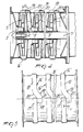
- the final portions 19′ of the volutes 16′ have an axial offset toward the region of the pump where the pressure rises, i.e. in the direction of the suction section of the subsequent stage.
- the offset s′ of the final portions 19′ of the volutes 16′ is such that the end of each terminal portion 19′ is arranged at the side of the initial portion 17′ of the subsequent volute.
- the diffusing and directing device comprises a plurality of suitably shaped and dimensioned volutes falling within the scope of the same general inventive concept.
- stator case according to the invention with metal plate, preferably stainless steel or other similar material.
- the process comprises a first step of blanking a metal plate disk and then of drawing of the blanked disk so as to obtain a hollow partly-finished item 27 with a substantially cylindrical lateral wall 28 which is open at one end, has an outer annular flange 29 and is closed at the opposite end by a substantially planar back wall 10.
- the partly-finished item 27 is stamped so as to assume the external configuration of the finished casing.
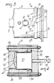
- Figure 6 schematically illustrates an apparatus for the stamping of the above described unfinished item, generally indicated by the reference numeral 28.
- the partly-finished item 27 is inserted into a cavity 32 of the fixture 33 formed by the segments 33, 34 and 35 which have an approximately cylindrical shape and can be mutually coaxially coupled.
- the inner walls of the end segment 33 and of the intermediate segment 34 define in negative the overall shape of the casing, whereas the end segment 35 defines the closure element of the fixture and has an annular step suitable for sealingly engaging the annular flange 29 of the partly-finished item 27.
- vent holes 40 are provided in the walls of the die 31 to connect its inner cavity 32 with the open atmosphere, in order to allow the free expansion of the partially-finished item inside said cavity.
- a tube 37 connected to inlet and outlet ducts, not illustrated in the figure, with the interposition of a throttle valve schematically indicated at 38.
- the inlet and outlet ducts can be connected to a central unit for supply pressurized oil or another equivalent technical incompressible fluid in order to introduce and extract the working liquid and exert thereon very high hydrostatic pressures of up to 2000 atmospheres (approximately 210 Mpa).
- pressurized oil or another equivalent technical incompressible fluid in order to introduce and extract the working liquid and exert thereon very high hydrostatic pressures of up to 2000 atmospheres (approximately 210 Mpa).
- the force exerted by the pressurized liquid on the inner surfaces of the partly-finished item 27 forces them to deform plastically against the inner walls of the cavity 32 until they assume the final external configuration of the finished case.
- the step of forming the semi-finished item 27 then provides the insertion of the item 31 into the cavity 32 of the fixture 31, the closure of the fixture by means of the bolts 36 so as to provide the tight sealing of the inner wall of the item 27, the insertion of the working liquid into the die from the inner side of the semiworked item 27 as described above, the removal of the liquid from the expanded item, the opening of the die and the extraction of the formed part.
- the part formed in the fixture 30 can subsequently be drilled and surface-finished so as to obtain the finished pump casing.
- the materials employed may be any according to the requirements and to the state of the art.
Landscapes
- Engineering & Computer Science (AREA)
- Mechanical Engineering (AREA)
- General Engineering & Computer Science (AREA)
- Physics & Mathematics (AREA)
- Fluid Mechanics (AREA)
- Structures Of Non-Positive Displacement Pumps (AREA)
- Non-Positive Displacement Air Blowers (AREA)
Applications Claiming Priority (2)
| Application Number | Priority Date | Filing Date | Title |
|---|---|---|---|
| IT8985615A IT1234126B (it) | 1989-07-05 | 1989-07-05 | Cassa statorica, particolarmente per pompa radiale centrifuga, nonche' metodo per la sua realizzazione |
| IT8561589 | 1989-07-05 |
Publications (3)
| Publication Number | Publication Date |
|---|---|
| EP0406787A2 true EP0406787A2 (de) | 1991-01-09 |
| EP0406787A3 EP0406787A3 (en) | 1991-06-26 |
| EP0406787B1 EP0406787B1 (de) | 1996-11-06 |
Family
ID=11329026
Family Applications (1)
| Application Number | Title | Priority Date | Filing Date |
|---|---|---|---|
| EP90112637A Expired - Lifetime EP0406787B1 (de) | 1989-07-05 | 1990-07-03 | Gehäuse, insbesondere für Radialkreiselpumpen und Verfahren zu dessen Herstellung |
Country Status (5)
| Country | Link |
|---|---|
| US (1) | US5040946A (de) |
| EP (1) | EP0406787B1 (de) |
| AT (1) | ATE145040T1 (de) |
| DE (1) | DE69029062T2 (de) |
| IT (1) | IT1234126B (de) |
Cited By (8)
| Publication number | Priority date | Publication date | Assignee | Title |
|---|---|---|---|---|
| EP0552661A1 (de) * | 1992-01-24 | 1993-07-28 | Ebara Corporation | Selbstansaugende Kreiselpumpe |
| EP0726397A1 (de) * | 1995-02-10 | 1996-08-14 | Ebara Corporation | Pumpe mit einem verbesserten Durchflusskanal |
| WO1998023864A1 (en) | 1996-11-27 | 1998-06-04 | Calpeda S.P.A. | Diffuser and conveyor device for a single-impeller centrigugal self-priming pump |
| ES2161191A1 (es) * | 2000-03-27 | 2001-11-16 | Bogemar Sl | Bomba centrifuga con hidroeyector. |
| EP1158178A1 (de) * | 2000-05-19 | 2001-11-28 | Nuovo Pignone Holding S.P.A. | Gehäuse für einen Radialverdichter und Herstellungsverfahren |
| ES2168205A1 (es) * | 2000-03-27 | 2002-06-01 | Bogemar Sl | Bomba centrifuaga autoaspirante. |
| ITVI20100075A1 (it) * | 2010-03-18 | 2011-09-19 | Calpeda A Spa | Pompa multistadio a tenuta perfezionata |
| EP2505842A1 (de) * | 2011-03-29 | 2012-10-03 | Grundfos Management a/s | Mehrstufiges Kreiselpumpenaggregat |
Families Citing this family (15)
| Publication number | Priority date | Publication date | Assignee | Title |
|---|---|---|---|---|
| US5235744A (en) * | 1989-07-05 | 1993-08-17 | Ebara Corporation | Method of manufacturing a centrifugal pump casing |
| US5131142A (en) * | 1990-10-30 | 1992-07-21 | Carrier Corporation | Method of making pipe diffuser structure |
| US5494403A (en) * | 1992-04-14 | 1996-02-27 | Ebara Corporation | Full-circumferential flow pump |
| US5402569A (en) * | 1994-02-28 | 1995-04-04 | Hypro Corporation | Method of manufacturing a pump with a modular cam profile liner |
| US5823739A (en) * | 1996-07-03 | 1998-10-20 | United Technologies Corporation | Containment case for a turbine engine |
| US6195889B1 (en) * | 1998-06-10 | 2001-03-06 | Tecumseh Products Company | Method to set slot width in a rotary compressor |
| WO2006017338A2 (en) * | 2004-07-13 | 2006-02-16 | Pump Engineering, Inc. | Centrifugal pump |
| US20090246039A1 (en) * | 2006-01-09 | 2009-10-01 | Grundfos Pumps Corporation | Carrier assembly for a pump |
| US7946810B2 (en) * | 2006-10-10 | 2011-05-24 | Grundfos Pumps Corporation | Multistage pump assembly |
| US8172523B2 (en) * | 2006-10-10 | 2012-05-08 | Grudfos Pumps Corporation | Multistage pump assembly having removable cartridge |
| US8245750B2 (en) * | 2008-02-11 | 2012-08-21 | Rohr, Inc. | Segmented mandrel for high temperature bonding of metallic axisymmetric shells having complex curvatures |
| US8584726B2 (en) * | 2008-02-11 | 2013-11-19 | Rohr, Inc. | Tool and method for bonding layers of a metallic axisymmetric structure having complex curvatures |
| US9334876B2 (en) | 2011-04-12 | 2016-05-10 | Thermo Neslab Inc. | Pump casing and related apparatus and methods |
| US9382034B2 (en) * | 2012-05-15 | 2016-07-05 | Silgan Containers Llc | Strengthened food container and method |
| US8978922B2 (en) | 2012-05-15 | 2015-03-17 | Silgan Containers Llc | Strengthened food container and method |
Family Cites Families (11)
| Publication number | Priority date | Publication date | Assignee | Title |
|---|---|---|---|---|
| GB191002385A (en) * | 1910-01-31 | 1910-12-01 | Ernst Vogel | Improvements relating to Centrifugal Pumps or the like. |
| US2372917A (en) * | 1941-07-01 | 1945-04-03 | Tuttle Wainwright | Apparatus for producing corrugated tubing |
| GB612664A (en) * | 1946-05-29 | 1948-11-16 | Nicolo Pensabene | Improvements in or relating to centrifugal pumps |
| US2634685A (en) * | 1949-02-17 | 1953-04-14 | Buchi Alfred | Improvement in the construction of outlet guide devices for centrifugal pumps or blowers |
| US2609775A (en) * | 1949-06-14 | 1952-09-09 | Production Tool & Die Co Inc | Hydraulic die |
| US3289923A (en) * | 1964-10-30 | 1966-12-06 | American Air Filter Co | Multi-stage pump |
| JPS5489970A (en) * | 1977-12-27 | 1979-07-17 | Tokyo Puresu Kougiyou Kk | Buldge molding |
| DD145944A1 (de) * | 1979-09-07 | 1981-01-14 | Friedbert Boekel | Leit-und rueckfuehreinrichtung fue mehrstufige kreiselpumpen |
| US4513598A (en) * | 1982-01-27 | 1985-04-30 | Costabile John J | Method and apparatus for producing a bulge in thin metal material |
| DE3716176A1 (de) * | 1987-05-14 | 1988-09-08 | Praezisions Werkzeuge Ag | Verfahren und vorrichtung zum umformen von hohlkoerpern sowie verwendung des verfahrens bzw. der vorrichtung und dosenkoerper |
| DK0379196T3 (da) * | 1989-01-19 | 1994-02-07 | Ebara Corp | Pumpehus |
-
1989
- 1989-07-05 IT IT8985615A patent/IT1234126B/it active
-
1990
- 1990-07-03 DE DE69029062T patent/DE69029062T2/de not_active Expired - Fee Related
- 1990-07-03 EP EP90112637A patent/EP0406787B1/de not_active Expired - Lifetime
- 1990-07-03 AT AT90112637T patent/ATE145040T1/de not_active IP Right Cessation
- 1990-07-05 US US07/548,378 patent/US5040946A/en not_active Expired - Lifetime
Cited By (17)
| Publication number | Priority date | Publication date | Assignee | Title |
|---|---|---|---|---|
| US5451139A (en) * | 1992-01-24 | 1995-09-19 | Ebara Corporation | Self priming centrifugal |
| EP0552661A1 (de) * | 1992-01-24 | 1993-07-28 | Ebara Corporation | Selbstansaugende Kreiselpumpe |
| CN1075877C (zh) * | 1995-02-10 | 2001-12-05 | 株式会社荏原制作所 | 具有改进的流动通道的泵 |
| EP0726397A1 (de) * | 1995-02-10 | 1996-08-14 | Ebara Corporation | Pumpe mit einem verbesserten Durchflusskanal |
| US5888053A (en) * | 1995-02-10 | 1999-03-30 | Ebara Corporation | Pump having first and second outer casing members |
| WO1998023864A1 (en) | 1996-11-27 | 1998-06-04 | Calpeda S.P.A. | Diffuser and conveyor device for a single-impeller centrigugal self-priming pump |
| ES2168205A1 (es) * | 2000-03-27 | 2002-06-01 | Bogemar Sl | Bomba centrifuaga autoaspirante. |
| ES2161191A1 (es) * | 2000-03-27 | 2001-11-16 | Bogemar Sl | Bomba centrifuga con hidroeyector. |
| EP1158178A1 (de) * | 2000-05-19 | 2001-11-28 | Nuovo Pignone Holding S.P.A. | Gehäuse für einen Radialverdichter und Herstellungsverfahren |
| US6506017B2 (en) | 2000-05-19 | 2003-01-14 | Nuovo Pignone Holding S.P.A. | Casing for centrifugal compressors and method for the manufacture thereof |
| ITVI20100075A1 (it) * | 2010-03-18 | 2011-09-19 | Calpeda A Spa | Pompa multistadio a tenuta perfezionata |
| EP2366905A2 (de) | 2010-03-18 | 2011-09-21 | CALPEDA S.p.A. | Mehrstufige Pumpe |
| CN102192190A (zh) * | 2010-03-18 | 2011-09-21 | 卡尔佩达有限公司 | 改进的密封多级泵 |
| EP2366905A3 (de) * | 2010-03-18 | 2012-11-21 | CALPEDA S.p.A. | Mehrstufige Pumpe |
| CN102192190B (zh) * | 2010-03-18 | 2014-01-29 | 卡尔佩达有限公司 | 改进的密封多级泵 |
| EP2505842A1 (de) * | 2011-03-29 | 2012-10-03 | Grundfos Management a/s | Mehrstufiges Kreiselpumpenaggregat |
| US9879680B2 (en) | 2011-03-29 | 2018-01-30 | Grundfos Management A/S | Multi-stage centrifugal pump unit |
Also Published As
| Publication number | Publication date |
|---|---|
| DE69029062T2 (de) | 1997-03-06 |
| US5040946A (en) | 1991-08-20 |
| IT8985615A0 (it) | 1989-07-05 |
| EP0406787B1 (de) | 1996-11-06 |
| IT1234126B (it) | 1992-04-29 |
| ATE145040T1 (de) | 1996-11-15 |
| DE69029062D1 (de) | 1996-12-12 |
| EP0406787A3 (en) | 1991-06-26 |
Similar Documents
| Publication | Publication Date | Title |
|---|---|---|
| US5040946A (en) | Case, particularly for centrifugal radial pumps, and method for manufacturing thereof | |
| EP0401670B1 (de) | Selbstansaugende Kreiselpumpe | |
| EP0413176B1 (de) | Blechgehäuse, insbesondere für Radialkreiselpumpen | |
| GB1508006A (en) | Unitary vacuum pump | |
| EP1352176B1 (de) | Selbstansaugendes pumpenaggregat | |
| US2753807A (en) | Centrifugal pump and method of manufacture therefor | |
| GB1339986A (en) | Multistage centrifugal pumps | |
| GB1506956A (en) | Pumps | |
| GB1386048A (en) | Centrifugal-type compressor assembly | |
| EP1216359B1 (de) | Kreiselpumpe | |
| EP0552661B1 (de) | Selbstansaugende Kreiselpumpe | |
| US4231702A (en) | Two-stage turbo compressor | |
| GB1364117A (en) | Multistage centrifugal pumps | |
| US3375789A (en) | Split case submersible pump | |
| SE312074B (de) | ||
| US3126831A (en) | Motor-pump unit | |
| US2960937A (en) | Submersible pump | |
| JPS6415498A (en) | Multi-stage centrifugal pump | |
| KR20080077675A (ko) | 연료 전지 압축기 시스템 | |
| CN212155197U (zh) | 一种多级离心风机 | |
| EP0093483A2 (de) | Zentrifugalpumpe | |
| US4012164A (en) | Rotor with recirculation | |
| CN221857082U (zh) | 离心压缩机及其叶轮结构 | |
| GB956731A (en) | Improvements in or relating to multiple stage centrifugal pumps, compressors or the like | |
| JPS6346720Y2 (de) |
Legal Events
| Date | Code | Title | Description |
|---|---|---|---|
| PUAI | Public reference made under article 153(3) epc to a published international application that has entered the european phase |
Free format text: ORIGINAL CODE: 0009012 |
|
| AK | Designated contracting states |
Kind code of ref document: A2 Designated state(s): AT BE CH DE DK ES FR GB GR IT LI LU NL SE |
|
| PUAL | Search report despatched |
Free format text: ORIGINAL CODE: 0009013 |
|
| AK | Designated contracting states |
Kind code of ref document: A3 Designated state(s): AT BE CH DE DK ES FR GB GR IT LI LU NL SE |
|
| 17P | Request for examination filed |
Effective date: 19911213 |
|
| 17Q | First examination report despatched |
Effective date: 19930630 |
|
| RAP1 | Party data changed (applicant data changed or rights of an application transferred) |
Owner name: EBARA CORPORATION |
|
| GRAH | Despatch of communication of intention to grant a patent |
Free format text: ORIGINAL CODE: EPIDOS IGRA |
|
| GRAH | Despatch of communication of intention to grant a patent |
Free format text: ORIGINAL CODE: EPIDOS IGRA |
|
| GRAA | (expected) grant |
Free format text: ORIGINAL CODE: 0009210 |
|
| AK | Designated contracting states |
Kind code of ref document: B1 Designated state(s): AT BE CH DE DK ES FR GB GR IT LI LU NL SE |
|
| PG25 | Lapsed in a contracting state [announced via postgrant information from national office to epo] |
Ref country code: NL Free format text: LAPSE BECAUSE OF FAILURE TO SUBMIT A TRANSLATION OF THE DESCRIPTION OR TO PAY THE FEE WITHIN THE PRESCRIBED TIME-LIMIT Effective date: 19961106 Ref country code: LI Effective date: 19961106 Ref country code: GR Free format text: LAPSE BECAUSE OF FAILURE TO SUBMIT A TRANSLATION OF THE DESCRIPTION OR TO PAY THE FEE WITHIN THE PRESCRIBED TIME-LIMIT Effective date: 19961106 Ref country code: FR Effective date: 19961106 Ref country code: ES Free format text: THE PATENT HAS BEEN ANNULLED BY A DECISION OF A NATIONAL AUTHORITY Effective date: 19961106 Ref country code: DK Effective date: 19961106 Ref country code: CH Effective date: 19961106 Ref country code: BE Effective date: 19961106 Ref country code: AT Effective date: 19961106 |
|
| REF | Corresponds to: |
Ref document number: 145040 Country of ref document: AT Date of ref document: 19961115 Kind code of ref document: T |
|
| REF | Corresponds to: |
Ref document number: 69029062 Country of ref document: DE Date of ref document: 19961212 |
|
| ITF | It: translation for a ep patent filed | ||
| PG25 | Lapsed in a contracting state [announced via postgrant information from national office to epo] |
Ref country code: SE Effective date: 19970206 |
|
| NLV1 | Nl: lapsed or annulled due to failure to fulfill the requirements of art. 29p and 29m of the patents act | ||
| EN | Fr: translation not filed | ||
| REG | Reference to a national code |
Ref country code: CH Ref legal event code: PL |
|
| PG25 | Lapsed in a contracting state [announced via postgrant information from national office to epo] |
Ref country code: GB Free format text: LAPSE BECAUSE OF NON-PAYMENT OF DUE FEES Effective date: 19970703 |
|
| PG25 | Lapsed in a contracting state [announced via postgrant information from national office to epo] |
Ref country code: LU Free format text: LAPSE BECAUSE OF NON-PAYMENT OF DUE FEES Effective date: 19970731 |
|
| PLBE | No opposition filed within time limit |
Free format text: ORIGINAL CODE: 0009261 |
|
| STAA | Information on the status of an ep patent application or granted ep patent |
Free format text: STATUS: NO OPPOSITION FILED WITHIN TIME LIMIT |
|
| 26N | No opposition filed | ||
| GBPC | Gb: european patent ceased through non-payment of renewal fee |
Effective date: 19970703 |
|
| PGFP | Annual fee paid to national office [announced via postgrant information from national office to epo] |
Ref country code: DE Payment date: 20050630 Year of fee payment: 16 |
|
| PGFP | Annual fee paid to national office [announced via postgrant information from national office to epo] |
Ref country code: IT Payment date: 20060731 Year of fee payment: 17 |
|
| PG25 | Lapsed in a contracting state [announced via postgrant information from national office to epo] |
Ref country code: DE Free format text: LAPSE BECAUSE OF NON-PAYMENT OF DUE FEES Effective date: 20070201 |
|
| PG25 | Lapsed in a contracting state [announced via postgrant information from national office to epo] |
Ref country code: IT Free format text: LAPSE BECAUSE OF NON-PAYMENT OF DUE FEES Effective date: 20070703 |