EP2505418B1 - Power storage device, power storage method, and program - Google Patents
Power storage device, power storage method, and program Download PDFInfo
- Publication number
- EP2505418B1 EP2505418B1 EP12001471.7A EP12001471A EP2505418B1 EP 2505418 B1 EP2505418 B1 EP 2505418B1 EP 12001471 A EP12001471 A EP 12001471A EP 2505418 B1 EP2505418 B1 EP 2505418B1
- Authority
- EP
- European Patent Office
- Prior art keywords
- charging
- secondary battery
- power
- power storage
- storage device
- Prior art date
- Legal status (The legal status is an assumption and is not a legal conclusion. Google has not performed a legal analysis and makes no representation as to the accuracy of the status listed.)
- Active
Links
Images


Classifications
-
- B—PERFORMING OPERATIONS; TRANSPORTING
- B60—VEHICLES IN GENERAL
- B60L—PROPULSION OF ELECTRICALLY-PROPELLED VEHICLES; SUPPLYING ELECTRIC POWER FOR AUXILIARY EQUIPMENT OF ELECTRICALLY-PROPELLED VEHICLES; ELECTRODYNAMIC BRAKE SYSTEMS FOR VEHICLES IN GENERAL; MAGNETIC SUSPENSION OR LEVITATION FOR VEHICLES; MONITORING OPERATING VARIABLES OF ELECTRICALLY-PROPELLED VEHICLES; ELECTRIC SAFETY DEVICES FOR ELECTRICALLY-PROPELLED VEHICLES
- B60L53/00—Methods of charging batteries, specially adapted for electric vehicles; Charging stations or on-board charging equipment therefor; Exchange of energy storage elements in electric vehicles
- B60L53/60—Monitoring or controlling charging stations
- B60L53/63—Monitoring or controlling charging stations in response to network capacity
-
- H—ELECTRICITY
- H02—GENERATION; CONVERSION OR DISTRIBUTION OF ELECTRIC POWER
- H02J—CIRCUIT ARRANGEMENTS OR SYSTEMS FOR SUPPLYING OR DISTRIBUTING ELECTRIC POWER; SYSTEMS FOR STORING ELECTRIC ENERGY
- H02J7/00—Circuit arrangements for charging or depolarising batteries or for supplying loads from batteries
- H02J7/007—Regulation of charging or discharging current or voltage
-
- H—ELECTRICITY
- H02—GENERATION; CONVERSION OR DISTRIBUTION OF ELECTRIC POWER
- H02J—CIRCUIT ARRANGEMENTS OR SYSTEMS FOR SUPPLYING OR DISTRIBUTING ELECTRIC POWER; SYSTEMS FOR STORING ELECTRIC ENERGY
- H02J7/00—Circuit arrangements for charging or depolarising batteries or for supplying loads from batteries
- H02J7/02—Circuit arrangements for charging or depolarising batteries or for supplying loads from batteries for charging batteries from ac mains by converters
- H02J7/04—Regulation of charging current or voltage
-
- B—PERFORMING OPERATIONS; TRANSPORTING
- B60—VEHICLES IN GENERAL
- B60L—PROPULSION OF ELECTRICALLY-PROPELLED VEHICLES; SUPPLYING ELECTRIC POWER FOR AUXILIARY EQUIPMENT OF ELECTRICALLY-PROPELLED VEHICLES; ELECTRODYNAMIC BRAKE SYSTEMS FOR VEHICLES IN GENERAL; MAGNETIC SUSPENSION OR LEVITATION FOR VEHICLES; MONITORING OPERATING VARIABLES OF ELECTRICALLY-PROPELLED VEHICLES; ELECTRIC SAFETY DEVICES FOR ELECTRICALLY-PROPELLED VEHICLES
- B60L2200/00—Type of vehicles
- B60L2200/26—Rail vehicles
-
- B—PERFORMING OPERATIONS; TRANSPORTING
- B60—VEHICLES IN GENERAL
- B60L—PROPULSION OF ELECTRICALLY-PROPELLED VEHICLES; SUPPLYING ELECTRIC POWER FOR AUXILIARY EQUIPMENT OF ELECTRICALLY-PROPELLED VEHICLES; ELECTRODYNAMIC BRAKE SYSTEMS FOR VEHICLES IN GENERAL; MAGNETIC SUSPENSION OR LEVITATION FOR VEHICLES; MONITORING OPERATING VARIABLES OF ELECTRICALLY-PROPELLED VEHICLES; ELECTRIC SAFETY DEVICES FOR ELECTRICALLY-PROPELLED VEHICLES
- B60L2260/00—Operating Modes
- B60L2260/40—Control modes
- B60L2260/50—Control modes by future state prediction
- B60L2260/58—Departure time prediction
-
- H—ELECTRICITY
- H02—GENERATION; CONVERSION OR DISTRIBUTION OF ELECTRIC POWER
- H02J—CIRCUIT ARRANGEMENTS OR SYSTEMS FOR SUPPLYING OR DISTRIBUTING ELECTRIC POWER; SYSTEMS FOR STORING ELECTRIC ENERGY
- H02J2310/00—The network for supplying or distributing electric power characterised by its spatial reach or by the load
- H02J2310/40—The network being an on-board power network, i.e. within a vehicle
- H02J2310/48—The network being an on-board power network, i.e. within a vehicle for electric vehicles [EV] or hybrid vehicles [HEV]
-
- Y—GENERAL TAGGING OF NEW TECHNOLOGICAL DEVELOPMENTS; GENERAL TAGGING OF CROSS-SECTIONAL TECHNOLOGIES SPANNING OVER SEVERAL SECTIONS OF THE IPC; TECHNICAL SUBJECTS COVERED BY FORMER USPC CROSS-REFERENCE ART COLLECTIONS [XRACs] AND DIGESTS
- Y02—TECHNOLOGIES OR APPLICATIONS FOR MITIGATION OR ADAPTATION AGAINST CLIMATE CHANGE
- Y02E—REDUCTION OF GREENHOUSE GAS [GHG] EMISSIONS, RELATED TO ENERGY GENERATION, TRANSMISSION OR DISTRIBUTION
- Y02E60/00—Enabling technologies; Technologies with a potential or indirect contribution to GHG emissions mitigation
-
- Y—GENERAL TAGGING OF NEW TECHNOLOGICAL DEVELOPMENTS; GENERAL TAGGING OF CROSS-SECTIONAL TECHNOLOGIES SPANNING OVER SEVERAL SECTIONS OF THE IPC; TECHNICAL SUBJECTS COVERED BY FORMER USPC CROSS-REFERENCE ART COLLECTIONS [XRACs] AND DIGESTS
- Y02—TECHNOLOGIES OR APPLICATIONS FOR MITIGATION OR ADAPTATION AGAINST CLIMATE CHANGE
- Y02T—CLIMATE CHANGE MITIGATION TECHNOLOGIES RELATED TO TRANSPORTATION
- Y02T10/00—Road transport of goods or passengers
- Y02T10/60—Other road transportation technologies with climate change mitigation effect
- Y02T10/70—Energy storage systems for electromobility, e.g. batteries
-
- Y—GENERAL TAGGING OF NEW TECHNOLOGICAL DEVELOPMENTS; GENERAL TAGGING OF CROSS-SECTIONAL TECHNOLOGIES SPANNING OVER SEVERAL SECTIONS OF THE IPC; TECHNICAL SUBJECTS COVERED BY FORMER USPC CROSS-REFERENCE ART COLLECTIONS [XRACs] AND DIGESTS
- Y02—TECHNOLOGIES OR APPLICATIONS FOR MITIGATION OR ADAPTATION AGAINST CLIMATE CHANGE
- Y02T—CLIMATE CHANGE MITIGATION TECHNOLOGIES RELATED TO TRANSPORTATION
- Y02T10/00—Road transport of goods or passengers
- Y02T10/60—Other road transportation technologies with climate change mitigation effect
- Y02T10/7072—Electromobility specific charging systems or methods for batteries, ultracapacitors, supercapacitors or double-layer capacitors
-
- Y—GENERAL TAGGING OF NEW TECHNOLOGICAL DEVELOPMENTS; GENERAL TAGGING OF CROSS-SECTIONAL TECHNOLOGIES SPANNING OVER SEVERAL SECTIONS OF THE IPC; TECHNICAL SUBJECTS COVERED BY FORMER USPC CROSS-REFERENCE ART COLLECTIONS [XRACs] AND DIGESTS
- Y02—TECHNOLOGIES OR APPLICATIONS FOR MITIGATION OR ADAPTATION AGAINST CLIMATE CHANGE
- Y02T—CLIMATE CHANGE MITIGATION TECHNOLOGIES RELATED TO TRANSPORTATION
- Y02T90/00—Enabling technologies or technologies with a potential or indirect contribution to GHG emissions mitigation
- Y02T90/10—Technologies relating to charging of electric vehicles
- Y02T90/12—Electric charging stations
-
- Y—GENERAL TAGGING OF NEW TECHNOLOGICAL DEVELOPMENTS; GENERAL TAGGING OF CROSS-SECTIONAL TECHNOLOGIES SPANNING OVER SEVERAL SECTIONS OF THE IPC; TECHNICAL SUBJECTS COVERED BY FORMER USPC CROSS-REFERENCE ART COLLECTIONS [XRACs] AND DIGESTS
- Y02—TECHNOLOGIES OR APPLICATIONS FOR MITIGATION OR ADAPTATION AGAINST CLIMATE CHANGE
- Y02T—CLIMATE CHANGE MITIGATION TECHNOLOGIES RELATED TO TRANSPORTATION
- Y02T90/00—Enabling technologies or technologies with a potential or indirect contribution to GHG emissions mitigation
- Y02T90/10—Technologies relating to charging of electric vehicles
- Y02T90/14—Plug-in electric vehicles
-
- Y—GENERAL TAGGING OF NEW TECHNOLOGICAL DEVELOPMENTS; GENERAL TAGGING OF CROSS-SECTIONAL TECHNOLOGIES SPANNING OVER SEVERAL SECTIONS OF THE IPC; TECHNICAL SUBJECTS COVERED BY FORMER USPC CROSS-REFERENCE ART COLLECTIONS [XRACs] AND DIGESTS
- Y02—TECHNOLOGIES OR APPLICATIONS FOR MITIGATION OR ADAPTATION AGAINST CLIMATE CHANGE
- Y02T—CLIMATE CHANGE MITIGATION TECHNOLOGIES RELATED TO TRANSPORTATION
- Y02T90/00—Enabling technologies or technologies with a potential or indirect contribution to GHG emissions mitigation
- Y02T90/10—Technologies relating to charging of electric vehicles
- Y02T90/16—Information or communication technologies improving the operation of electric vehicles
-
- Y—GENERAL TAGGING OF NEW TECHNOLOGICAL DEVELOPMENTS; GENERAL TAGGING OF CROSS-SECTIONAL TECHNOLOGIES SPANNING OVER SEVERAL SECTIONS OF THE IPC; TECHNICAL SUBJECTS COVERED BY FORMER USPC CROSS-REFERENCE ART COLLECTIONS [XRACs] AND DIGESTS
- Y04—INFORMATION OR COMMUNICATION TECHNOLOGIES HAVING AN IMPACT ON OTHER TECHNOLOGY AREAS
- Y04S—SYSTEMS INTEGRATING TECHNOLOGIES RELATED TO POWER NETWORK OPERATION, COMMUNICATION OR INFORMATION TECHNOLOGIES FOR IMPROVING THE ELECTRICAL POWER GENERATION, TRANSMISSION, DISTRIBUTION, MANAGEMENT OR USAGE, i.e. SMART GRIDS
- Y04S10/00—Systems supporting electrical power generation, transmission or distribution
- Y04S10/12—Monitoring or controlling equipment for energy generation units, e.g. distributed energy generation [DER] or load-side generation
- Y04S10/126—Monitoring or controlling equipment for energy generation units, e.g. distributed energy generation [DER] or load-side generation the energy generation units being or involving electric vehicles [EV] or hybrid vehicles [HEV], i.e. power aggregation of EV or HEV, vehicle to grid arrangements [V2G]
Definitions
- the present disclosure relates to power storage devices, power storage methods, and programs.
- WO 20011/018959 A1 also published as EP 2 466 719 A1 , describes an electronic device in which a charging current is set on the basis of stored charging history information indicating a time period in which a user performs charging. Further information on a user's schedule read from network devices may be used to alter the charging current.
- a secondary battery In addition to the above-mentioned usage, a secondary battery is expected to be widely used in various other applications. However, there is a problem in that a secondary battery deteriorates after repeated charge-discharge operations, with the result that the voltage and electric energy of the secondary battery decrease.
- a power storage system that prevents a secondary battery from being charged with an excessively high charging current and increases the life of the secondary battery is disclosed, for example, in Japanese Unexamined Patent Application Publication No. 2010-41883 .
- a period during which an amount of charge electric energy in the power storage system increases is determined, as a restrictive period during which a charging current value has to be limited, on the basis of remaining amount of electric energy of a battery, consumption patterns of power consumed by loads, and power generation prediction patterns, and the charging current value during the restrictive period is calculated. Therefore, the battery is prevented from being charged with an excessively high charging current and the life of the battery can be prolonged.
- the suppression of the deterioration is achieved by keeping the secondary battery in a full-charge state only at the time near to a period during which the secondary battery is supposed to be continuously used for a long time, and by keeping the secondary battery in a charged state that is lower than the full-charge state during a period in which the secondary battery and an external power source are used in parallel for a long time.
- a charging current value is calculated on the basis of the load and a predicted power generation amount, and a period necessary for a stored electric energy level in the power storage system to reach to a predetermined target electric energy level is determined.
- a charging current value is calculated on the basis of the load and a predicted power generation amount, and a period necessary for a stored electric energy level in the power storage system to reach to a predetermined target electric energy level is determined.
- one of the cases of degradation of a secondary battery is a charging current having a large value. In other words, the more rapidly the secondary battery is charged up, the more the secondary battery deteriorates.
- Japanese Unexamined Patent Application Publication No. 2010-41883 the deterioration of a secondary battery is not taken into consideration when the value of the charging current is determined.
- embodiments of the present disclosure are intended to provide newly-developed and improved power storage devices and power storage methods that are capable of controlling charging of a secondary battery so that the suppression of the deterioration of the secondary battery and the prolongation of the life of the secondary battery are realized, and a program used for the above power storage devices and the power storage methods.
- An embodiment of the present disclosure provides a power storage device that includes a secondary battery; an acquisition unit that acquires charging period information for charging the secondary battery; and a charge control unit that calculates a charging power value on the basis of the charging period information and controls charging power used for charging the secondary battery so that the value of the charging power is equal to the calculated charging power value.
- the embodiment of the present disclosure provides a power storage method that includes the procedures of: acquiring charging period information for charging a secondary battery; calculating a charging power value on the basis of the charging period information; and controlling charging power used for charging the secondary battery so that the value of the charging power is equal to the calculated charging power value.
- the embodiment of the present disclosure provides a program that causes a computer to execute the processes of: acquiring charging period information for charging a secondary battery; calculating a charging power value on the basis of the charging period information; and controlling charging power used for charging the secondary battery so that the value of the charging power is equal to the calculated charging power value.
- the embodiment of the present disclosure can perform charge control that is capable of controlling charging of a secondary battery so that the suppression of the deterioration of the secondary battery and the prolongation of the life of the secondary battery are realized.
- each of the power storage devices in the above embodiments to be respectively described later includes:
- FIG. 1 is an overall view showing a power storage system according to an embodiment of the present disclosure.
- the power storage system according to the embodiment of the present disclosure includes a commercial power source 10 and a power storage device 20 mounted on an electric car 2.
- the power storage device 20 is charged by being supplied electric power from the commercial power source 10, and supplies electric power stored in itself to each device of the electric car 2.
- This power storage device 20 is designed in such a manner that, when a charging period is determined, it charges the relevant secondary battery with a charging current the value of which is necessarily and sufficiently large enough to fully charge the secondary battery in the charging period. Therefore, the power storage device 20 according to the embodiment of the present disclosure is capable of avoiding unnecessarily rapid charging, with the result that the suppression of the deterioration of the secondary battery and the prolongation of the life of the secondary battery are realized.
- FIG. 1 shows the power storage device 20 that is mounted on the electric car 2 and supplies electric power to each device mounted on the electric car 2 as an example
- a physical object on which the power storage device 20 is mounted on is not limited to an electric car and target objects to which the power storage device 20 supplies electric power are not limited to devices such as those mounted on an electric car.
- the power storage device 20 can be mounted on various vehicles such as an electric car, an electric train, and an airplane, or can be mounted on mobile terminal devices such as a portable PC (personal computer) and a cellular phone.
- the power storage device 20 is used for supplying electric power to household electric appliances such as a household display apparatus and a household air-conditioning apparatus other than the above-mentioned vehicles and machines.
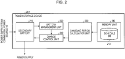
- FIG. 2 is a functional block diagram of a power storage device 20-1 according to a first embodiment of the present disclosure.
- the power storage device 20-1 according to the first embodiment includes a secondary battery 210, a battery management unit 220, a charging period calculation unit 230, a memory unit 240, and a charge control unit 250. Each unit will be described below.
- the secondary battery 210 is a battery that can be used many times after being repeatedly charged. Electric power stored in the secondary battery 210 is converted from direct-current power to alternating-current power when necessary, and the converted power is supplied to a physical object on which the power storage 20-1 is mounted, for example, to an electric car 2.
- the battery management unit 220 is a detection unit that detects remaining amount of electric energy of the secondary battery 210 by monitoring the secondary battery 210. For example, the battery management unit 220 can calculate the remaining amount of electric energy of the secondary battery 210 by measuring the difference between the current battery voltage of the secondary battery 210 and the battery voltage when the secondary battery 210 is full-charge because the battery voltage is apt to decrease in accordance with the amount of electric energy consumed in the secondary battery 210. Alternatively, it is conceivable that the battery management unit 220 calculates the remaining amount of electric energy of the secondary battery 210 in consideration of the difference between input power input to the secondary battery 210 and output power output from the secondary battery 210 acquired by measuring the input power and output power. The battery management unit 220 sends information concerning the detected remaining amount of electric energy to the charge control unit 250.
- the charging period calculation unit 230 acquires schedule information from a schedule DB (database) 241 stored in the memory unit 240, and calculates a charging period on the basis of the acquired schedule information.
- the schedule information is schedule information concerning the usage of the electric car 2 on which the power storage device 20-1 is mounted.
- the charging period calculation unit 230 calculates the charging period within a time zone in which the electric car 2 is supposed not to be used on the basis of the acquired schedule information.
- the memory unit 240 stores the schedule DB 241 in which a user records his/her schedule.
- a schedule concerning the usage of the electric car 2 is recorded in the schedule DB 241 as an example of a schedule.
- a schedule is recorded in the schedule DB 241 using an input interface (not shown) such as a keyboard or a mouse.
- the user can record schedule information, which is stored in a PC (personal computer) or a mobile terminal device, in the schedule DB 241 by synchronizing the schedule DB 241 with the schedule information.
- the charge control unit 250 calculates a charging power value on the basis of the charging period calculated by the charging period calculation unit 230 and the remaining amount of electric energy of the secondary battery 210 detected by the battery management unit 220, and controls charging power used for charging the secondary battery 210 so that the value of the charging power is equal to the calculated charging power value. To put it concretely, the charge control unit 250 can calculate, as the charging power value, a power value to provide a necessary amount of electric energy within the charging period calculated by the charging period calculation unit 230.
- the necessary amount of electric energy can be a difference between the full-charge electric energy of the secondary battery 210 and the remaining amount of electric energy of the secondary battery 210 detected by the battery management unit 220, or can be a difference between an electric energy that is a predetermined fraction of the full-charge electric energy of the secondary battery 210 and the remaining amount of electric energy of the secondary battery 210 detected by the battery management unit 220.
- the charge control unit 250 can calculate a charging power value on the basis of a charging period calculated by the charging period calculation unit 230 without using the remaining amount of electric energy of the secondary battery 210.
- the charge control unit 250 can regard the full-charge electric energy of the secondary battery 210 as electric energy necessary to charge the secondary battery 210 regardless of the remaining electric energy of the secondary battery 210.
- the secondary battery 210 can be full-charge up within the charging period calculated by the charging period calculation unit 230.
- the charge control unit 250 can set this amount of to-be-consumed electric energy to be the amount of electric energy necessary to charge the secondary battery 210.
- the charge control unit 250 can set the average amount of consumed electric energy or the maximum amount of consumed electric energy to be the amount of electric energy necessary to charge the secondary battery 210.
- the configuration of the power storage device 20-1 according to the first embodiment has been described with reference to FIG. 2 .
- the operation processes of the power storage device 20-1 according to the first embodiment will be described with reference to FIG. 3 .
- FIG. 3 is a flowchart showing processes of a power storage method according to the first embodiment of the present disclosure.
- the battery management unit 220 detects the remaining amount of electric energy of the secondary battery 210, and sends information concerning the remaining amount of electric energy to the charge control unit 250 at step S201.
- the charging period calculation unit 230 acquires schedule information, which was recorded in advance by a user, from the memory unit 240.
- the charging period calculation unit 230 calculates a charging period on the basis of the acquired schedule information.
- schedule information which was recorded in advance by a user
- the charging period calculation unit 230 calculates a charging period on the basis of the acquired schedule information.
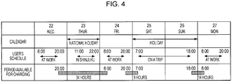
- FIG. 4 is an explanatory diagram showing an example of a user's schedule according to the first embodiment of the present disclosure.
- the user who has this schedule goes to work at about 8 a.m. and comes home at about 8 p.m. weekdays.
- This user intends to go on a trip using his/her electric car on the 25th (Saturday) and 26th (Sunday), and his/her schedule time of departure is 7 a.m. on the 25th and his/her schedule time of return is 6 p.m. on the 26th.
- On the 23rd (Thursday) he/she intends to go to Shinjuku, but will not use his/her electric car (this schedule is indicated by a dashed line).
- Such a schedule as this is recorded in the schedule DB 241 in advance by the user as a piece of information used for setting a period that can be used for charging a secondary battery because his/her electric car will not be used during the period.
- the charging period calculation unit 230 can determine a charging period for charging the secondary battery 210 within the 34-hour period that is supposed to be available for charging.
- the 14-hour period from 6 p.m. on the 26th (Sunday) to 8 a.m. on the 27th (Monday) are periods that can be used for charging the power storage device 20-1. Therefore, the charging period calculation unit 230 can determine the charging period for charging the power storage device 20-1 within the above period of 9 hours or 14 hours.
- the charging period calculation unit 230 calculates a charging period using not only schedule information concerning one user but also schedule information concerning plural users. For example, in recent years, a car-sharing service in which plural members share a car has become widely used. In this service, it is necessary that a member notifies the other members of his/her time period for using the car in advance in order for the members to effectively use the car. Therefore, it is conceivable that the charging period calculation unit 230 calculates a charging period used for charging the shared car on the basis of information concerning plural members' time periods for using the car.
- the charge control unit 250 calculates a charging power value at step S207 on the basis of the charging period calculated at step S205.
- a concrete example of a charging power value calculation that the charge control unit 250 performs will be shown below.
- a necessary amount of electric energy for charging that is a difference between an amount of target charge electric energy and remaining amount of electric energy of the secondary battery 210 by C (kWh), a charging period by t (h), and a charging voltage by V (V).
- the minimum charging current necessary to give the necessary amount of electric energy to the secondary battery is represented by C ⁇ 1000/t/V (A).
- the necessary amount of electric energy C for charging the secondary battery from its empty state to its fully charged state is 21 kWh
- the charging period is 14 h
- the charging voltage is 100 V
- the charging period is 7 (h)
- the charging current is doubled, that is, it becomes 30 (A).
- charging with the use of a time period supposed to be available for the charging makes it possible to keep the charging current low, with the result that the deterioration of the secondary battery can be suppressed.
- step S209 the charge control unit 250 charges the secondary battery 210 with the charging power value calculated at step S205.
- the charge control unit 250 can repeatedly determine whether the charging power value is to be recalculated or not at step S211. This function of the charge control unit 250 is prepared for the reason that there is a possibility that information concerning the remaining amount of electric energy of the secondary battery 210 detected at step S201 and the charging power value calculated at step 207 is not theoretically accurate. Generally speaking, because the characteristics of the secondary battery are influenced by the type of battery, the degree of deterioration, temperature, usage, and the like, it is difficult to perform accurate calculation of the remaining amount of electric energy of the battery and scheduled charge control. Therefore, repeated recalculation of the charging power value is performed in order to complete the charging within a charging period. Step S211 can be performed at predetermined time intervals. If the recalculation is performed, the flow goes back to step S201, and if the recalculation is not performed, the flow proceeds to step S213.
- step S213 the charge control unit 250 judges whether charging the secondary battery 210 is completed or not. If charging is completed, the power storage process shown in FIG. 3 ends. If charging is not completed, the flow goes back to step S209, and the charging is continued.
- the above-described power storage process can be started by a trigger showing that the secondary battery has entered a chargeable state.
- a trigger showing that the secondary battery has entered a chargeable state.
- the power storage device 20-1 detects that a charging plug is connected to the electric car 2, and can start the power storage process upon being triggered by this detection.
- the schedule in FIG. 4 in the case where the user comes home at 8 p.m. on the 22nd (Wednesday), and connects a charging plug to an electric car, 34 hours from 8 p.m. on the 22nd (Wednesday) to 8 a.m. on the 24th (Friday) that is his/her schedule time of using the electric car is set to be a period that can be used for charging.
- the target electric energy information used for calculating the charging power value by the charge control unit 250 at step S207 is not limited to information concerning the full-charge electric energy.
- an amount of target electric energy can be determined in accordance with the time period. If the time period during which the electric car 2 is used is short, the amount of target electric energy can be 80 % of the full-charge electric energy. In this case, the judgment that charging is completed is made when remaining amount of electric energy becomes 80 % of the full-charge electric energy.
- the charging voltage is set to be 100 V, and the charging power is suppressed to a low level by changing the charging current in accordance with the charging period
- the power storage process according to the embodiments of the present disclosure is not limited to this example, and it is conceivable that the charging voltage value is made selectable (i.e., the charging method is made selectable).
- the electric car 2 is designed so that it can be charged with a single phase-voltage 100 V power source, a single-phase voltage 200 V power source, and a three-phase voltage 200 V power source (for rapid charging).
- a charging period corresponding to a single phase-voltage 100 V power source is longer than a charging period corresponding to a single-phase voltage 200 V power source
- the charging period corresponding to a single phase-voltage 200 V power source is longer than a charging period corresponding to a three-phase voltage 200 V power source (for rapid charging).
- a degree of deterioration of the secondary battery corresponding to a single phase-voltage 100 V power source is smaller than a degree of deterioration corresponding to a single-phase voltage 200 V power source, and the degree of deterioration corresponding to a single phase-voltage 200 V power source is smaller than a degree of deterioration corresponding to a three-phase voltage 200 V power source (for rapid charging). Therefore, in order to prolong the life of the battery, it is recommendable that a single phase-voltage 100 V power source is used for charging.
- the charge control unit 250 automatically selects a lowest possible voltage power source in accordance with the charging period calculated on the basis of information concerning the user's schedule, which makes it possible to prevent the deterioration of the battery without hampering the user's convenience.
- a power storage device 20-2 according to a second embodiment of the present disclosure will be described hereinafter.
- a charging period was calculated using information concerning a user's schedule in the above-described first embodiment, a charging period is calculated on the basis of a user's usage history in the second embodiment.
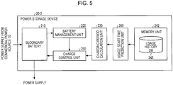
- FIG. 5 is a block configuration diagram of the power storage device 20-2 according to the second embodiment of the present disclosure.
- the power storage device 20-2 includes a secondary battery 210, a battery management unit 220, a charging period calculation unit 230, a memory unit 242, a usage start time prediction unit 260, and a charge control unit 250.
- the memory unit 242 stores a usage history DB 243.
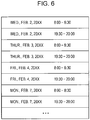
- the usage history DB 243 records usage history information of the power storage device 20-2. For example, as shown in FIG. 6 , usage history information concerning an electric car 2 on which the power storage device 20-2 is mounted is automatically recorded in the usage history DB 243.
- the usage start time prediction unit 260 acquires user's usage history information from the memory unit 242, and predicts a time when the user starts using the electric car 2 on the basis of the user's usage history information. In addition, the usage start time prediction unit 260 sends the information concerning the predicted usage start time to the charging period calculation unit 230.
- the charging period calculation unit 230 calculates a time period from the charging start time to the usage start time predicted by the usage start time prediction unit 260 or a part of the time period from the charging start time to the usage start time predicted by the usage start time prediction unit 260 as a charging period.
- the charge control unit 250 controls charging power used for charging the secondary battery 210 on the basis of the charging period calculated by the charging period calculation unit 230 and remaining amount of electric energy of the secondary battery 210 detected by the battery management unit 220.
- the detailed description about the content of the charge control has already been made in the first embodiment, they will be omitted.
- the above-described second embodiment can suppress the deterioration of a secondary battery and prolong the life of the secondary battery.
- the second embodiment can save a user's trouble of having to explicitly input information concerning his/her schedule into the schedule DB 241.
- the battery management unit 220 detects remaining amount of electric energy of the secondary battery 210, and sends information concerning the remaining amount of electric energy to the charge control unit 250 at step S221.
- the usage start time prediction unit 260 acquires usage history information from the memory unit 242.
- the usage start time prediction unit 260 subsequently predicts a usage start time on the basis of the acquired usage history information at step S225.
- the charging period calculation unit 230 calculates a charging period on the basis of the usage start time predicted at step S225.
- the charging period can be a period from the charging start time to the usage start time, or a part of the period from the charging start time to the usage start time.
- the charging period can be calculated without troubling the user.
- the usage history information of FIG. 6 shows a set usage pattern that the electric car 2 is used for a time period from 8:00 to 8:30 and a time period from 19:30 to 20:00 on weekdays. Therefore, if the electric car 2 becomes ready to be charged at 20:00 on Thursday, it can be predicted by the usage start time prediction unit 260 that a user starts using the electric car 2 at 8:00 the next day judging from the above usage pattern. Therefore, the charging period calculation unit 230 can set a time period from 20:00 to 8:00 the next day as the charging period for the electric car 2.
- step S 229 the charge control unit 250 calculates a charging power value on the basis of the charging period calculated at step S227.
- step S231 the charge control unit 250 charges the secondary battery 210 with the charging power value calculated at step S229.
- the charge control unit 250 can repeatedly judge whether the charging power value is recalculated or not at step S233. If the recalculation is performed, the flow goes back to step S221, and if the recalculation is not performed, the flow proceeds to step S235.
- step S235 the charge control unit 250 judges whether charging the secondary battery 210 is completed or not. If charging is completed, the power storage process shown in FIG. 7 ends. If charging is not completed, the flow goes back to step S231, and charging is continued.
- a power storage device 20-3 according to a third embodiment of the present disclosure will be described hereinafter.
- a charging period was calculated using information concerning a user's schedule in the above-described first embodiment, the calculation of a charging period based on the information concerning the user's schedule is not necessary because a charging period directly input by the user is used in this third embodiment. Therefore, the power storage device 20-3 according to this embodiment can cope with an emergent demand for charging.
- the power storage device 20-3 includes a secondary battery 210, a battery management unit 220, a charging period input unit 270, and a charge control unit 250.
- the charging period input unit 270 acquires charging period information by receiving the charging period information input by a user.
- the charging period information received by the charging period input unit 270 is sent to the charge control unit 250.
- the charge control unit 250 controls charging power used for charging the secondary battery 210 on the basis of the charging period sent from the charging period input unit 270 and remaining amount of electric energy of the secondary battery 210 detected by the battery management unit 220.
- the charge control unit 250 controls charging power used for charging the secondary battery 210 on the basis of the charging period sent from the charging period input unit 270 and remaining amount of electric energy of the secondary battery 210 detected by the battery management unit 220.
- this third embodiment may prevent a secondary battery 210 from being charged with an unnecessarily rapid charging current.
- the battery management unit 220 detects remaining amount of electric energy of the secondary battery 210, and sends information concerning the remaining amount of electric energy to the charge control unit 250 at step S241.
- charging period information is input into the charging period input unit 270 by a user.
- an electric car is charged, for example, at a parking spot in a commercial architecture other than at home or at a battery charging station.
- the electric car 2 parked at the parking spot is charged, which is considerably convenient for the user.
- the user takes how long he/she stays in the commercial architecture into consideration when inputting charging period into the charging period input unit 270. In this way, the secondary battery 2 can be charged with a charging power value in accordance with the length of the user's stay.
- the charge control unit 250 calculates the charging power value on the basis of the charging period calculated at step S243.
- the charge control unit 250 subsequently charges the secondary battery 210 with the charging power value calculated at step 245.
- the charge control unit 250 can repeatedly judge whether the charging power value is recalculated or not at step S249. If the recalculation is performed, the flow goes back to step S241, and if the recalculation is not performed, the flow proceeds to step S251.
- step S251 the charge control unit 250 judges whether charging the secondary battery 210 is completed or not. If charging is completed, the power storage process shown in FIG. 9 ends. If charging is not completed, the flow goes back to step S247, and charging is continued.
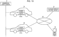
- the power storage system includes a power storage device 20-4a mounted on an electric car 2a, a power storage device 20-4b mounted on an electric car 2b, and a charging period control device 30, and a mobile terminal device 50, and a network 40 that connects the power storage devices 20-4a, 20-4b, the charging period control device 30, and the mobile terminal device 5 with each other.
- the power storage device 20-4 includes a secondary battery 210, a battery management unit 220, a communication unit 280, and a charge control unit 250.
- the communication unit 280 is connected to the charging period control device 30 via the network 40, and receives charging period information from the charging period control device 30.
- the communication unit 280 sends the received charging period information to the charge control unit 250.
- the communication unit 280 is connected to the network 40 via a wireless LAN (local area network) communication function, via a wireless communication function such as a 4G communication function, or via a wire communication function.
- the charging period control device 30 includes a charging period calculation unit 330, a memory unit 340, and a communication unit 380.
- the charging period calculation unit 330 acquires schedule information from a schedule DB (database) 341 stored in the memory unit 240, and calculates a charging period on the basis of the acquired schedule information as is the case with the charging period calculation unit 230 described in the first embodiment. Subsequently, the charging period calculation unit 330 sends the calculated charging period information to the communication unit 380.
- schedule DB database
- the memory unit 340 stores the schedule DB 341 in which a user recorded his/her schedule.
- the user can record schedule information, which is stored in a mobile terminal device 50, in the schedule DB 341 by synchronizing the schedule DB 341 with the schedule information.
- the communication unit 380 which is connected to the power storage device 20-4 via the network 40, sends the charging period information to the power storage device 20-4.
- the communication unit 380 can acquire the schedule information from the mobile terminal device 50 because it is connected to the mobile terminal device 50 via the network 40.
- FIG. 13 is a time chart of a power storage method according the fourth embodiment of the present disclosure. As shown in FIG. 13 , first, the battery management unit 220 of the power storage device 20-4 detects the remaining amount of electric energy of the secondary battery 210, and sends information concerning the remaining amount of electric energy to the charge control unit 250 at step S300.
- the charging period calculation unit 330 of the charging period control device 30 acquires schedule information from the memory unit 340, and calculates a charging period on the basis of the acquired schedule information.
- the charging period control device 30 sends the charging period calculated at step S301 via the communication unit 380.
- the charging period control device 30 can sends the charging period information in response to a request from the power storage device 20-4.
- the charge control unit 250 of the power storage device 20-4 calculates a charging power value on the basis of the charging period information sent from the charging period control device 30 at step S303.
- step S307 the charge control unit 250 charges the secondary battery 210 with the charging power value calculated at step S305.
- step S209 to step 213 in FIG. 3 which are some of the operation processes of the above-described first embodiment, can be performed although they are not shown in FIG. 13 .
- schedule information used for calculating a charging period is managed through a network.
- a power storage devices 20-1 that includes a charging period calculation unit 230 and a memory unit 240 storing a schedule DB 241 is mounted
- the charging period control device 30 which can be connected to a network, includes the charging period calculation unit 330 and the memory unit 340 that stores the schedule DB 341, plural power storage devices can share schedules. Therefore, users have only to record usage schedules of plural power storage devices in the charging period control device 30 that collectively manages the usage schedules.
- the charging period control device 30 can be accessed with the use of a mobile terminal device 50, the remote operation of a power storage process can be performed. For example, a user who is out can control the charging period for an electric car 2 at home by changing the usage schedule of the electric car 2.
- the power storage device 20 can prevent the secondary battery from being charged with an unnecessarily rapid charging current, so that the suppression of the deterioration of the secondary battery and the prolongation of the life of the secondary battery are realized.
- a combination of the above-described embodiments can be used.
- the relevant usage history can be used for calculating the charging period, or if the charging period is input by a user, this charging period can be directly used.
- recording a schedule or inputting a charging period can be done by the user with the use of a mobile terminal device.
Applications Claiming Priority (1)
| Application Number | Priority Date | Filing Date | Title |
|---|---|---|---|
| JP2011075766A JP5982736B2 (ja) | 2011-03-30 | 2011-03-30 | 蓄電装置、蓄電方法およびプログラム |
Publications (3)
| Publication Number | Publication Date |
|---|---|
| EP2505418A2 EP2505418A2 (en) | 2012-10-03 |
| EP2505418A3 EP2505418A3 (en) | 2016-06-22 |
| EP2505418B1 true EP2505418B1 (en) | 2019-10-16 |
Family
ID=45939070
Family Applications (1)
| Application Number | Title | Priority Date | Filing Date |
|---|---|---|---|
| EP12001471.7A Active EP2505418B1 (en) | 2011-03-30 | 2012-03-05 | Power storage device, power storage method, and program |
Country Status (4)
| Country | Link |
|---|---|
| US (1) | US9193276B2 (ja) |
| EP (1) | EP2505418B1 (ja) |
| JP (1) | JP5982736B2 (ja) |
| CN (1) | CN102738855B (ja) |
Families Citing this family (14)
| Publication number | Priority date | Publication date | Assignee | Title |
|---|---|---|---|---|
| FR2978626B1 (fr) * | 2011-07-26 | 2013-08-16 | Commissariat Energie Atomique | Recharge d'un parc de batteries |
| US9929581B2 (en) | 2012-09-24 | 2018-03-27 | Nissan Motor Co., Ltd. | Charge control device and charge control method |
| JP6051841B2 (ja) * | 2012-12-21 | 2016-12-27 | 三菱電機株式会社 | 貯湯式給湯システム |
| CN103682498B (zh) * | 2013-12-04 | 2016-03-02 | 华为终端有限公司 | 一种充电方法及电子设备 |
| JP2015154593A (ja) * | 2014-02-14 | 2015-08-24 | ソニー株式会社 | 充放電制御装置、電池パック、電子機器、電動車両および充放電制御方法 |
| JP2016021845A (ja) * | 2014-07-16 | 2016-02-04 | 株式会社 ハセテック | 充電装置及び充電制御装置 |
| CN104362684A (zh) * | 2014-10-10 | 2015-02-18 | 华为技术有限公司 | 充电方法和可充电设备 |
| EP3248826A1 (de) * | 2016-05-27 | 2017-11-29 | E.ON Czech Holding AG | System zur versorgung einer verbrauchereinheit mit netz-spannung |
| CN109417300B (zh) * | 2016-07-13 | 2023-04-28 | 索尼移动通信株式会社 | 信息处理装置和充电方法 |
| JP6897495B2 (ja) * | 2017-10-27 | 2021-06-30 | トヨタ自動車株式会社 | 配車システム及び配車方法 |
| FR3078837B1 (fr) * | 2018-03-09 | 2021-07-16 | E Xteq Europe | Procede de commande pour le chargement de batterie d’un vehicule |
| US11862772B2 (en) * | 2018-03-29 | 2024-01-02 | Canal Electronics LLC | User-defined battery recharging systems and methods |
| JP2020115701A (ja) * | 2019-01-17 | 2020-07-30 | 株式会社豊田自動織機 | 充電システム |
| US11165270B2 (en) | 2019-03-21 | 2021-11-02 | Microsoft Technology Licensing, Llc | Predictive management of battery operation |
Family Cites Families (19)
| Publication number | Priority date | Publication date | Assignee | Title |
|---|---|---|---|---|
| JPH0360847A (ja) | 1989-07-28 | 1991-03-15 | Kawasaki Steel Corp | 双方向引抜型水平連鋳機の鋳型支持装置 |
| JPH087793Y2 (ja) * | 1989-10-09 | 1996-03-04 | ミツミ電機株式会社 | 充電器の充電電流制御装置 |
| JP2001008376A (ja) * | 1999-06-22 | 2001-01-12 | Canon Inc | 充電制御装置及びその方法、並びに電池を有する装置 |
| JP2002315204A (ja) * | 2001-04-18 | 2002-10-25 | Matsushita Electric Ind Co Ltd | 充電管理装置 |
| JP2004094607A (ja) * | 2002-08-30 | 2004-03-25 | Matsushita Electric Ind Co Ltd | 携帯情報機器、及びその充電状態最適化方法とプログラム、並びに、電池管理サーバ、及びそれによる電池式電気機器の充電状態最適化方法とプログラム |
| JP2004318629A (ja) * | 2003-04-18 | 2004-11-11 | Canon Electronics Inc | 電子機器 |
| JP2005160256A (ja) * | 2003-11-27 | 2005-06-16 | Canon Inc | 充電方法、充電装置、プログラム及び記憶媒体 |
| JP4311357B2 (ja) * | 2005-01-27 | 2009-08-12 | 株式会社デンソー | 車両のバッテリ充電状態推定装置 |
| JP4798087B2 (ja) * | 2007-07-10 | 2011-10-19 | トヨタ自動車株式会社 | 電力システムおよびそれを備えた車両 |
| US7782021B2 (en) * | 2007-07-18 | 2010-08-24 | Tesla Motors, Inc. | Battery charging based on cost and life |
| US7693609B2 (en) * | 2007-09-05 | 2010-04-06 | Consolidated Edison Company Of New York, Inc. | Hybrid vehicle recharging system and method of operation |
| JP4333798B2 (ja) * | 2007-11-30 | 2009-09-16 | トヨタ自動車株式会社 | 充電制御装置および充電制御方法 |
| JP2010041883A (ja) | 2008-08-07 | 2010-02-18 | Panasonic Corp | 蓄電システム |
| JP4735683B2 (ja) * | 2008-08-22 | 2011-07-27 | ソニー株式会社 | 充電装置及び充電方法 |
| FR2942358B1 (fr) * | 2009-02-17 | 2011-01-28 | Peugeot Citroen Automobiles Sa | Systeme et procede de gestion de recharge d'une batterie |
| JP5287409B2 (ja) * | 2009-03-25 | 2013-09-11 | 日本電気株式会社 | バッテリ充電システム、車両管理サーバ、カーシェアリングサーバ、管理方法、プログラム及び記録媒体 |
| EP2466719B1 (en) * | 2009-08-11 | 2015-09-30 | Sony Corporation | Electronic device, method for charging electronic device, program, charging control device, and charging control method |
| JP5467505B2 (ja) | 2009-09-30 | 2014-04-09 | 株式会社リコー | トナーの製造方法、トナー及び現像剤 |
| US20120249065A1 (en) * | 2011-04-01 | 2012-10-04 | Michael Bissonette | Multi-use energy management and conversion system including electric vehicle charging |
-
2011
- 2011-03-30 JP JP2011075766A patent/JP5982736B2/ja not_active Expired - Fee Related
-
2012
- 2012-03-05 EP EP12001471.7A patent/EP2505418B1/en active Active
- 2012-03-20 US US13/424,997 patent/US9193276B2/en not_active Expired - Fee Related
- 2012-03-23 CN CN201210080843.8A patent/CN102738855B/zh not_active Expired - Fee Related
Non-Patent Citations (1)
| Title |
|---|
| None * |
Also Published As
| Publication number | Publication date |
|---|---|
| EP2505418A2 (en) | 2012-10-03 |
| CN102738855B (zh) | 2016-12-21 |
| US20120249088A1 (en) | 2012-10-04 |
| US9193276B2 (en) | 2015-11-24 |
| JP5982736B2 (ja) | 2016-08-31 |
| JP2012210130A (ja) | 2012-10-25 |
| CN102738855A (zh) | 2012-10-17 |
| EP2505418A3 (en) | 2016-06-22 |
Similar Documents
| Publication | Publication Date | Title |
|---|---|---|
| EP2505418B1 (en) | Power storage device, power storage method, and program | |
| US11081901B2 (en) | Wireless charging of mobile devices | |
| US9698617B2 (en) | Frequency based rechargeable power source charging | |
| US7415623B2 (en) | System for managing the power source life between multiple individually powered devices in a wired system and method of using same | |
| JP5659549B2 (ja) | 電力制御システム、電力制御方法、制御装置、プログラム、及び、サーバ装置 | |
| JP5187776B2 (ja) | 電気機器 | |
| CN108604820B (zh) | 管理装置和控制方法 | |
| US10033214B2 (en) | Power supply-demand adjusting apparatus, power system and power supply-demand adjusting method | |
| JP6256844B2 (ja) | 電力管理装置、電力管理システム、電力管理方法 | |
| US20170052274A1 (en) | Resident presence-absence state determination device, delivery system, method for determining resident presence-absence state, program for determining resident presence-absence state, and terminal for delivery | |
| US20130009468A1 (en) | Electronic apparatus, and charging control method | |
| JPWO2012020756A1 (ja) | 電力制御装置 | |
| JP6734756B2 (ja) | 蓄電池制御システム及び電力供給システム | |
| US9979190B2 (en) | System and method for energy shedding | |
| CN111903027A (zh) | 电力信息管理系统、管理方法、程序、电力信息管理服务器、通信终端以及电力系统 | |
| US9876350B2 (en) | Power supply system | |
| US20130193906A1 (en) | Terminals, terminal systems and charging/discharging methods thereof | |
| CN114204631A (zh) | 放电控制方法、充电控制方法和装置 | |
| JPWO2016185671A1 (ja) | 蓄電池制御装置 | |
| JP5862750B2 (ja) | 電力制御システム、電力制御方法、制御装置、プログラム、及び、サーバ装置 | |
| JP6450168B2 (ja) | 電力管理システム、電力管理方法、および電力管理プログラム | |
| CN116131370A (zh) | 储能电池的充放电方法、装置、设备以及可读存储介质 |
Legal Events
| Date | Code | Title | Description |
|---|---|---|---|
| PUAI | Public reference made under article 153(3) epc to a published international application that has entered the european phase |
Free format text: ORIGINAL CODE: 0009012 |
|
| 17P | Request for examination filed |
Effective date: 20120305 |
|
| AK | Designated contracting states |
Kind code of ref document: A2 Designated state(s): AL AT BE BG CH CY CZ DE DK EE ES FI FR GB GR HR HU IE IS IT LI LT LU LV MC MK MT NL NO PL PT RO RS SE SI SK SM TR |
|
| AX | Request for extension of the european patent |
Extension state: BA ME |
|
| PUAL | Search report despatched |
Free format text: ORIGINAL CODE: 0009013 |
|
| AK | Designated contracting states |
Kind code of ref document: A3 Designated state(s): AL AT BE BG CH CY CZ DE DK EE ES FI FR GB GR HR HU IE IS IT LI LT LU LV MC MK MT NL NO PL PT RO RS SE SI SK SM TR |
|
| AX | Request for extension of the european patent |
Extension state: BA ME |
|
| RIC1 | Information provided on ipc code assigned before grant |
Ipc: B60L 11/18 20060101AFI20160517BHEP |
|
| STAA | Information on the status of an ep patent application or granted ep patent |
Free format text: STATUS: EXAMINATION IS IN PROGRESS |
|
| 17Q | First examination report despatched |
Effective date: 20170113 |
|
| REG | Reference to a national code |
Ref country code: DE Ref legal event code: R079 Ref document number: 602012064842 Country of ref document: DE Free format text: PREVIOUS MAIN CLASS: B60L0011180000 Ipc: B60L0053630000 |
|
| RIC1 | Information provided on ipc code assigned before grant |
Ipc: B60L 53/63 20190101AFI20190325BHEP Ipc: H02J 7/04 20060101ALI20190325BHEP |
|
| GRAP | Despatch of communication of intention to grant a patent |
Free format text: ORIGINAL CODE: EPIDOSNIGR1 |
|
| STAA | Information on the status of an ep patent application or granted ep patent |
Free format text: STATUS: GRANT OF PATENT IS INTENDED |
|
| INTG | Intention to grant announced |
Effective date: 20190506 |
|
| GRAS | Grant fee paid |
Free format text: ORIGINAL CODE: EPIDOSNIGR3 |
|
| GRAA | (expected) grant |
Free format text: ORIGINAL CODE: 0009210 |
|
| STAA | Information on the status of an ep patent application or granted ep patent |
Free format text: STATUS: THE PATENT HAS BEEN GRANTED |
|
| AK | Designated contracting states |
Kind code of ref document: B1 Designated state(s): AL AT BE BG CH CY CZ DE DK EE ES FI FR GB GR HR HU IE IS IT LI LT LU LV MC MK MT NL NO PL PT RO RS SE SI SK SM TR |
|
| REG | Reference to a national code |
Ref country code: GB Ref legal event code: FG4D |
|
| REG | Reference to a national code |
Ref country code: CH Ref legal event code: EP |
|
| REG | Reference to a national code |
Ref country code: DE Ref legal event code: R096 Ref document number: 602012064842 Country of ref document: DE |
|
| REG | Reference to a national code |
Ref country code: IE Ref legal event code: FG4D |
|
| REG | Reference to a national code |
Ref country code: AT Ref legal event code: REF Ref document number: 1190945 Country of ref document: AT Kind code of ref document: T Effective date: 20191115 |
|
| REG | Reference to a national code |
Ref country code: NL Ref legal event code: MP Effective date: 20191016 |
|
| REG | Reference to a national code |
Ref country code: LT Ref legal event code: MG4D |
|
| REG | Reference to a national code |
Ref country code: AT Ref legal event code: MK05 Ref document number: 1190945 Country of ref document: AT Kind code of ref document: T Effective date: 20191016 |
|
| PG25 | Lapsed in a contracting state [announced via postgrant information from national office to epo] |
Ref country code: ES Free format text: LAPSE BECAUSE OF FAILURE TO SUBMIT A TRANSLATION OF THE DESCRIPTION OR TO PAY THE FEE WITHIN THE PRESCRIBED TIME-LIMIT Effective date: 20191016 Ref country code: AT Free format text: LAPSE BECAUSE OF FAILURE TO SUBMIT A TRANSLATION OF THE DESCRIPTION OR TO PAY THE FEE WITHIN THE PRESCRIBED TIME-LIMIT Effective date: 20191016 Ref country code: NL Free format text: LAPSE BECAUSE OF FAILURE TO SUBMIT A TRANSLATION OF THE DESCRIPTION OR TO PAY THE FEE WITHIN THE PRESCRIBED TIME-LIMIT Effective date: 20191016 Ref country code: LV Free format text: LAPSE BECAUSE OF FAILURE TO SUBMIT A TRANSLATION OF THE DESCRIPTION OR TO PAY THE FEE WITHIN THE PRESCRIBED TIME-LIMIT Effective date: 20191016 Ref country code: SE Free format text: LAPSE BECAUSE OF FAILURE TO SUBMIT A TRANSLATION OF THE DESCRIPTION OR TO PAY THE FEE WITHIN THE PRESCRIBED TIME-LIMIT Effective date: 20191016 Ref country code: PL Free format text: LAPSE BECAUSE OF FAILURE TO SUBMIT A TRANSLATION OF THE DESCRIPTION OR TO PAY THE FEE WITHIN THE PRESCRIBED TIME-LIMIT Effective date: 20191016 Ref country code: NO Free format text: LAPSE BECAUSE OF FAILURE TO SUBMIT A TRANSLATION OF THE DESCRIPTION OR TO PAY THE FEE WITHIN THE PRESCRIBED TIME-LIMIT Effective date: 20200116 Ref country code: LT Free format text: LAPSE BECAUSE OF FAILURE TO SUBMIT A TRANSLATION OF THE DESCRIPTION OR TO PAY THE FEE WITHIN THE PRESCRIBED TIME-LIMIT Effective date: 20191016 Ref country code: GR Free format text: LAPSE BECAUSE OF FAILURE TO SUBMIT A TRANSLATION OF THE DESCRIPTION OR TO PAY THE FEE WITHIN THE PRESCRIBED TIME-LIMIT Effective date: 20200117 Ref country code: PT Free format text: LAPSE BECAUSE OF FAILURE TO SUBMIT A TRANSLATION OF THE DESCRIPTION OR TO PAY THE FEE WITHIN THE PRESCRIBED TIME-LIMIT Effective date: 20200217 Ref country code: FI Free format text: LAPSE BECAUSE OF FAILURE TO SUBMIT A TRANSLATION OF THE DESCRIPTION OR TO PAY THE FEE WITHIN THE PRESCRIBED TIME-LIMIT Effective date: 20191016 Ref country code: BG Free format text: LAPSE BECAUSE OF FAILURE TO SUBMIT A TRANSLATION OF THE DESCRIPTION OR TO PAY THE FEE WITHIN THE PRESCRIBED TIME-LIMIT Effective date: 20200116 |
|
| PG25 | Lapsed in a contracting state [announced via postgrant information from national office to epo] |
Ref country code: RS Free format text: LAPSE BECAUSE OF FAILURE TO SUBMIT A TRANSLATION OF THE DESCRIPTION OR TO PAY THE FEE WITHIN THE PRESCRIBED TIME-LIMIT Effective date: 20191016 Ref country code: HR Free format text: LAPSE BECAUSE OF FAILURE TO SUBMIT A TRANSLATION OF THE DESCRIPTION OR TO PAY THE FEE WITHIN THE PRESCRIBED TIME-LIMIT Effective date: 20191016 Ref country code: IS Free format text: LAPSE BECAUSE OF FAILURE TO SUBMIT A TRANSLATION OF THE DESCRIPTION OR TO PAY THE FEE WITHIN THE PRESCRIBED TIME-LIMIT Effective date: 20200224 |
|
| PG25 | Lapsed in a contracting state [announced via postgrant information from national office to epo] |
Ref country code: AL Free format text: LAPSE BECAUSE OF FAILURE TO SUBMIT A TRANSLATION OF THE DESCRIPTION OR TO PAY THE FEE WITHIN THE PRESCRIBED TIME-LIMIT Effective date: 20191016 |
|
| REG | Reference to a national code |
Ref country code: DE Ref legal event code: R097 Ref document number: 602012064842 Country of ref document: DE |
|
| PG2D | Information on lapse in contracting state deleted |
Ref country code: IS |
|
| PG25 | Lapsed in a contracting state [announced via postgrant information from national office to epo] |
Ref country code: RO Free format text: LAPSE BECAUSE OF FAILURE TO SUBMIT A TRANSLATION OF THE DESCRIPTION OR TO PAY THE FEE WITHIN THE PRESCRIBED TIME-LIMIT Effective date: 20191016 Ref country code: DK Free format text: LAPSE BECAUSE OF FAILURE TO SUBMIT A TRANSLATION OF THE DESCRIPTION OR TO PAY THE FEE WITHIN THE PRESCRIBED TIME-LIMIT Effective date: 20191016 Ref country code: EE Free format text: LAPSE BECAUSE OF FAILURE TO SUBMIT A TRANSLATION OF THE DESCRIPTION OR TO PAY THE FEE WITHIN THE PRESCRIBED TIME-LIMIT Effective date: 20191016 Ref country code: CZ Free format text: LAPSE BECAUSE OF FAILURE TO SUBMIT A TRANSLATION OF THE DESCRIPTION OR TO PAY THE FEE WITHIN THE PRESCRIBED TIME-LIMIT Effective date: 20191016 Ref country code: IS Free format text: LAPSE BECAUSE OF FAILURE TO SUBMIT A TRANSLATION OF THE DESCRIPTION OR TO PAY THE FEE WITHIN THE PRESCRIBED TIME-LIMIT Effective date: 20200216 |
|
| PLBE | No opposition filed within time limit |
Free format text: ORIGINAL CODE: 0009261 |
|
| STAA | Information on the status of an ep patent application or granted ep patent |
Free format text: STATUS: NO OPPOSITION FILED WITHIN TIME LIMIT |
|
| PG25 | Lapsed in a contracting state [announced via postgrant information from national office to epo] |
Ref country code: SK Free format text: LAPSE BECAUSE OF FAILURE TO SUBMIT A TRANSLATION OF THE DESCRIPTION OR TO PAY THE FEE WITHIN THE PRESCRIBED TIME-LIMIT Effective date: 20191016 Ref country code: IT Free format text: LAPSE BECAUSE OF FAILURE TO SUBMIT A TRANSLATION OF THE DESCRIPTION OR TO PAY THE FEE WITHIN THE PRESCRIBED TIME-LIMIT Effective date: 20191016 Ref country code: SM Free format text: LAPSE BECAUSE OF FAILURE TO SUBMIT A TRANSLATION OF THE DESCRIPTION OR TO PAY THE FEE WITHIN THE PRESCRIBED TIME-LIMIT Effective date: 20191016 |
|
| 26N | No opposition filed |
Effective date: 20200717 |
|
| PG25 | Lapsed in a contracting state [announced via postgrant information from national office to epo] |
Ref country code: MC Free format text: LAPSE BECAUSE OF FAILURE TO SUBMIT A TRANSLATION OF THE DESCRIPTION OR TO PAY THE FEE WITHIN THE PRESCRIBED TIME-LIMIT Effective date: 20191016 |
|
| REG | Reference to a national code |
Ref country code: CH Ref legal event code: PL |
|
| PG25 | Lapsed in a contracting state [announced via postgrant information from national office to epo] |
Ref country code: SI Free format text: LAPSE BECAUSE OF FAILURE TO SUBMIT A TRANSLATION OF THE DESCRIPTION OR TO PAY THE FEE WITHIN THE PRESCRIBED TIME-LIMIT Effective date: 20191016 |
|
| REG | Reference to a national code |
Ref country code: BE Ref legal event code: MM Effective date: 20200331 |
|
| PG25 | Lapsed in a contracting state [announced via postgrant information from national office to epo] |
Ref country code: LU Free format text: LAPSE BECAUSE OF NON-PAYMENT OF DUE FEES Effective date: 20200305 |
|
| PG25 | Lapsed in a contracting state [announced via postgrant information from national office to epo] |
Ref country code: IE Free format text: LAPSE BECAUSE OF NON-PAYMENT OF DUE FEES Effective date: 20200305 Ref country code: CH Free format text: LAPSE BECAUSE OF NON-PAYMENT OF DUE FEES Effective date: 20200331 Ref country code: LI Free format text: LAPSE BECAUSE OF NON-PAYMENT OF DUE FEES Effective date: 20200331 |
|
| PG25 | Lapsed in a contracting state [announced via postgrant information from national office to epo] |
Ref country code: BE Free format text: LAPSE BECAUSE OF NON-PAYMENT OF DUE FEES Effective date: 20200331 |
|
| PGFP | Annual fee paid to national office [announced via postgrant information from national office to epo] |
Ref country code: FR Payment date: 20210218 Year of fee payment: 10 |
|
| PGFP | Annual fee paid to national office [announced via postgrant information from national office to epo] |
Ref country code: DE Payment date: 20210217 Year of fee payment: 10 Ref country code: GB Payment date: 20210219 Year of fee payment: 10 |
|
| PG25 | Lapsed in a contracting state [announced via postgrant information from national office to epo] |
Ref country code: TR Free format text: LAPSE BECAUSE OF FAILURE TO SUBMIT A TRANSLATION OF THE DESCRIPTION OR TO PAY THE FEE WITHIN THE PRESCRIBED TIME-LIMIT Effective date: 20191016 Ref country code: MT Free format text: LAPSE BECAUSE OF FAILURE TO SUBMIT A TRANSLATION OF THE DESCRIPTION OR TO PAY THE FEE WITHIN THE PRESCRIBED TIME-LIMIT Effective date: 20191016 Ref country code: CY Free format text: LAPSE BECAUSE OF FAILURE TO SUBMIT A TRANSLATION OF THE DESCRIPTION OR TO PAY THE FEE WITHIN THE PRESCRIBED TIME-LIMIT Effective date: 20191016 |
|
| PG25 | Lapsed in a contracting state [announced via postgrant information from national office to epo] |
Ref country code: MK Free format text: LAPSE BECAUSE OF FAILURE TO SUBMIT A TRANSLATION OF THE DESCRIPTION OR TO PAY THE FEE WITHIN THE PRESCRIBED TIME-LIMIT Effective date: 20191016 |
|
| REG | Reference to a national code |
Ref country code: DE Ref legal event code: R119 Ref document number: 602012064842 Country of ref document: DE |
|
| GBPC | Gb: european patent ceased through non-payment of renewal fee |
Effective date: 20220305 |
|
| PG25 | Lapsed in a contracting state [announced via postgrant information from national office to epo] |
Ref country code: GB Free format text: LAPSE BECAUSE OF NON-PAYMENT OF DUE FEES Effective date: 20220305 Ref country code: FR Free format text: LAPSE BECAUSE OF NON-PAYMENT OF DUE FEES Effective date: 20220331 Ref country code: DE Free format text: LAPSE BECAUSE OF NON-PAYMENT OF DUE FEES Effective date: 20221001 |