EP2505334B1 - Dispositif d'injection et procédé d'injection de résine - Google Patents
Dispositif d'injection et procédé d'injection de résine Download PDFInfo
- Publication number
- EP2505334B1 EP2505334B1 EP10832990.5A EP10832990A EP2505334B1 EP 2505334 B1 EP2505334 B1 EP 2505334B1 EP 10832990 A EP10832990 A EP 10832990A EP 2505334 B1 EP2505334 B1 EP 2505334B1
- Authority
- EP
- European Patent Office
- Prior art keywords
- resin
- path
- holding pressure
- injection
- shutoff
- Prior art date
- Legal status (The legal status is an assumption and is not a legal conclusion. Google has not performed a legal analysis and makes no representation as to the accuracy of the status listed.)
- Active
Links
- 239000011347 resin Substances 0.000 title claims description 189
- 229920005989 resin Polymers 0.000 title claims description 189
- 238000002347 injection Methods 0.000 title claims description 127
- 239000007924 injection Substances 0.000 title claims description 127
- 238000000034 method Methods 0.000 title claims description 19
- 238000003825 pressing Methods 0.000 claims description 23
- 230000033001 locomotion Effects 0.000 claims description 18
- 238000007599 discharging Methods 0.000 claims description 2
- 239000000463 material Substances 0.000 description 7
- 239000012778 molding material Substances 0.000 description 3
- IKHGUXGNUITLKF-UHFFFAOYSA-N Acetaldehyde Chemical compound CC=O IKHGUXGNUITLKF-UHFFFAOYSA-N 0.000 description 2
- 235000013361 beverage Nutrition 0.000 description 2
- 238000001746 injection moulding Methods 0.000 description 2
- BQCADISMDOOEFD-UHFFFAOYSA-N Silver Chemical compound [Ag] BQCADISMDOOEFD-UHFFFAOYSA-N 0.000 description 1
- 238000000071 blow moulding Methods 0.000 description 1
- 235000012206 bottled water Nutrition 0.000 description 1
- 239000000470 constituent Substances 0.000 description 1
- 238000001816 cooling Methods 0.000 description 1
- 230000003247 decreasing effect Effects 0.000 description 1
- 230000007812 deficiency Effects 0.000 description 1
- 239000003651 drinking water Substances 0.000 description 1
- 230000000694 effects Effects 0.000 description 1
- 238000009434 installation Methods 0.000 description 1
- 238000004519 manufacturing process Methods 0.000 description 1
- 238000000465 moulding Methods 0.000 description 1
- 229910052709 silver Inorganic materials 0.000 description 1
- 239000004332 silver Substances 0.000 description 1
Images

Classifications
-
- B—PERFORMING OPERATIONS; TRANSPORTING
- B29—WORKING OF PLASTICS; WORKING OF SUBSTANCES IN A PLASTIC STATE IN GENERAL
- B29C—SHAPING OR JOINING OF PLASTICS; SHAPING OF MATERIAL IN A PLASTIC STATE, NOT OTHERWISE PROVIDED FOR; AFTER-TREATMENT OF THE SHAPED PRODUCTS, e.g. REPAIRING
- B29C45/00—Injection moulding, i.e. forcing the required volume of moulding material through a nozzle into a closed mould; Apparatus therefor
- B29C45/17—Component parts, details or accessories; Auxiliary operations
- B29C45/46—Means for plasticising or homogenising the moulding material or forcing it into the mould
- B29C45/57—Exerting after-pressure on the moulding material
-
- B—PERFORMING OPERATIONS; TRANSPORTING
- B29—WORKING OF PLASTICS; WORKING OF SUBSTANCES IN A PLASTIC STATE IN GENERAL
- B29B—PREPARATION OR PRETREATMENT OF THE MATERIAL TO BE SHAPED; MAKING GRANULES OR PREFORMS; RECOVERY OF PLASTICS OR OTHER CONSTITUENTS OF WASTE MATERIAL CONTAINING PLASTICS
- B29B11/00—Making preforms
- B29B11/06—Making preforms by moulding the material
- B29B11/08—Injection moulding
-
- B—PERFORMING OPERATIONS; TRANSPORTING
- B29—WORKING OF PLASTICS; WORKING OF SUBSTANCES IN A PLASTIC STATE IN GENERAL
- B29C—SHAPING OR JOINING OF PLASTICS; SHAPING OF MATERIAL IN A PLASTIC STATE, NOT OTHERWISE PROVIDED FOR; AFTER-TREATMENT OF THE SHAPED PRODUCTS, e.g. REPAIRING
- B29C45/00—Injection moulding, i.e. forcing the required volume of moulding material through a nozzle into a closed mould; Apparatus therefor
- B29C45/17—Component parts, details or accessories; Auxiliary operations
- B29C45/46—Means for plasticising or homogenising the moulding material or forcing it into the mould
- B29C45/47—Means for plasticising or homogenising the moulding material or forcing it into the mould using screws
- B29C45/50—Axially movable screw
-
- B—PERFORMING OPERATIONS; TRANSPORTING
- B29—WORKING OF PLASTICS; WORKING OF SUBSTANCES IN A PLASTIC STATE IN GENERAL
- B29C—SHAPING OR JOINING OF PLASTICS; SHAPING OF MATERIAL IN A PLASTIC STATE, NOT OTHERWISE PROVIDED FOR; AFTER-TREATMENT OF THE SHAPED PRODUCTS, e.g. REPAIRING
- B29C45/00—Injection moulding, i.e. forcing the required volume of moulding material through a nozzle into a closed mould; Apparatus therefor
- B29C45/17—Component parts, details or accessories; Auxiliary operations
- B29C45/46—Means for plasticising or homogenising the moulding material or forcing it into the mould
- B29C45/53—Means for plasticising or homogenising the moulding material or forcing it into the mould using injection ram or piston
- B29C45/54—Means for plasticising or homogenising the moulding material or forcing it into the mould using injection ram or piston and plasticising screw
-
- B—PERFORMING OPERATIONS; TRANSPORTING
- B29—WORKING OF PLASTICS; WORKING OF SUBSTANCES IN A PLASTIC STATE IN GENERAL
- B29K—INDEXING SCHEME ASSOCIATED WITH SUBCLASSES B29B, B29C OR B29D, RELATING TO MOULDING MATERIALS OR TO MATERIALS FOR MOULDS, REINFORCEMENTS, FILLERS OR PREFORMED PARTS, e.g. INSERTS
- B29K2067/00—Use of polyesters or derivatives thereof, as moulding material
- B29K2067/003—PET, i.e. poylethylene terephthalate
-
- B—PERFORMING OPERATIONS; TRANSPORTING
- B29—WORKING OF PLASTICS; WORKING OF SUBSTANCES IN A PLASTIC STATE IN GENERAL
- B29K—INDEXING SCHEME ASSOCIATED WITH SUBCLASSES B29B, B29C OR B29D, RELATING TO MOULDING MATERIALS OR TO MATERIALS FOR MOULDS, REINFORCEMENTS, FILLERS OR PREFORMED PARTS, e.g. INSERTS
- B29K2105/00—Condition, form or state of moulded material or of the material to be shaped
- B29K2105/25—Solid
- B29K2105/253—Preform
-
- B—PERFORMING OPERATIONS; TRANSPORTING
- B29—WORKING OF PLASTICS; WORKING OF SUBSTANCES IN A PLASTIC STATE IN GENERAL
- B29L—INDEXING SCHEME ASSOCIATED WITH SUBCLASS B29C, RELATING TO PARTICULAR ARTICLES
- B29L2031/00—Other particular articles
- B29L2031/712—Containers; Packaging elements or accessories, Packages
- B29L2031/7158—Bottles
Definitions
- the present invention also relates to a resin injection method for injecting the resin, with the pressure of the resin being maintained in the resin path of the injection nozzle, according to claim 1.
- This invention relates to an injection device equipped with a means for maintaining the pressure of a resin in a resin path of an injection nozzle, according to claim 4.
- PET bottles for example, are frequently used as bottles for potable water, etc.
- the PET bottle is produced in the shape of a bottle by forming a test tube-shaped preform with the use of an injection molding device (injection device), and blow-molding the preform.
- injection device injection molding device
- an in-line screw type injection device is known for example from JP-A-9-8570 .
- a metering step of supplying a new resin material into an injection cylinder, an injection step of extruding and charging the resin material into a mold, and a holding pressure (dwelling) step of maintaining the pressure of the resin material within a resin path are repeatedly performed.
- the injection step and the holding pressure step are completed and before the injection step of a next cycle is started, cooling of a molded product, mold opening, withdrawal of the molded product, and mold closing are carried out. During this process, the metering step is performed.
- the resin path is closed by a dedicated plunger or the like to maintain the pressure of the resin material. During this period, an injection screw is moved backward, and a new resin material is supplied into the injection cylinder.
- the resin path is pressurized by a holding pressure mechanism.
- the resin has flowed into the resin charging site of the holding pressure mechanism (the holding pressure mechanism and the resin are in contact). If the resin flowing into the holding pressure mechanism (charging site) resides there, various deficiencies such as burn marks are induced. Thus, the resin flowing into the holding pressure mechanism needs to be discharged into the resin path to eliminate residence.
- Patent US-A-6017210 discloses an injection method and device of the related art.
- the pressure holding means comprises a plunger, the forward movement of which is limited to prevent its projection into the holding pressure path. Similar devices are known from JP-A-01-241418 and GB-A-2116903 .
- the present invention has been accomplished in the light of the above-mentioned circumstances. It is an object of the present invention to provide an injection device and a resin injection method which can reliably eliminate the residence of the resin even with the use of an inexpensive holding pressure mechanism.
- the object is solved according to the present invention by an injection method according to any one of claims 1-3 and a device according to any one of claims 4-5.
- the present invention makes it possible to provide an injection device and a resin injection method which can reliably eliminate the residence of a resin, even with the use of a holding pressure mechanism which is not extensive and not expensive.
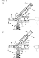
- the configuration of the injection device according to the embodiment of the present invention will be described based on Fig. 1 and Figs. 2(a), 2(b) .
- the illustrated injection device is intended to be applied, for example, as an injection device for forming a preform in the shape of a test tube during the process for preparing a beverage bottle from a resin.
- An injection-molded product is not limited to the preform, and the injection device of the present invention can be used as an injection device for obtaining various molded products.
- Figs. 1 , 2(a) and 2(b) show the sectional state of a leading end portion (an injection nozzle portion) of the injection device according to the embodiment of the present invention, in which Fig. 1 shows a state where a resin is injected, Fig. 2(a) shows a state where a resin path is closed to maintain the pressure of the resin, and Fig. 2(b) shows a state where the resin path is opened, and the pressure of the resin is maintained.
- a hopper for supplying a molding material, a drive device for rotationally driving an injection screw, and so on are provided, although these members are not shown.
- an injection screw 2 is supported inside an injection cylinder 1, and an injection nozzle 3 is mounted at the front end of the injection cylinder 1.
- a hopper for supplying a molding material is connected to the injection cylinder 1, and the molding material is supplied into the injection cylinder 1.
- a screw head 4 is provided at the front end of the injection screw 2, and the injection screw 2 is rotationally driven to plasticize the resin heated and melted within the injection cylinder 1.
- the injection screw 2 is moved backward.
- an injecting drive cylinder 5 is driven to move the injection screw 2 forward, performing the injection of the molten resin.
- a resin path 6 is formed inside the injection cylinder 1, and the injection nozzle 3 is connected to the front end of the resin path 6.
- the injection nozzle 3 is connected to a mold via a hot runner (not shown) .
- a shutoff device 8, as a shutoff means, is connected in an integral state to the injection nozzle 3, and the resin path 6 is free to be shut off by the shutoff device 8.
- a holding pressure path 9 communicating with the resin path 6 is formed.
- the holding pressure path 9 is formed to be inclined rearwardly (rightwardly in the drawings) with respect to the resin path 6, and the resin charged into the holding pressure path 9 and the resin path 6 has its pressure maintained by a holding pressure device 10.
- the shutoff device 8 is equipped with a shutoff cylinder 11 integrated with the injection cylinder 1, and a piston rod portion 13 of a shutoff plunger 12 is reciprocatably supported in the shutoff cylinder 11.
- a shutoff drive cylinder 14 is connected to the shutoff cylinder 11, and a shutoff piston 15 is reciprocatably supported in the shutoff drive cylinder 14.
- the shutoff drive cylinder 14 is supplied with a pressure oil, and the pressure oil is discharged from the shutoff drive cylinder 14, whereby the shutoff piston 15 is driven to reciprocate.
- the shutoff piston 15 of the shutoff drive cylinder 14 is connected to the piston rod portion 13 of the shutoff plunger 12, and the shutoff plunger 12 is reciprocated (moved forward and backward) by the driving of the shutoff drive cylinder 14 via the shutoff piston 15 and the piston rod portion 13. As shown in Figs. 2(a), 2(b) , the shutoff plunger 12 moves forward (makes a closing motion), thereby shutting off (closing) the resin path 6 forward of the screw head 4.
- the holding pressure device 10 is equipped with a holding pressure cylinder 21 integrated with the injection cylinder 1, and a piston rod portion 23 of a holding pressure plunger 22 is reciprocatably supported in the holding pressure cylinder 21.
- the holding pressure plunger 22 is disposed in the holding pressure path 9 so as to be capable of reciprocating (movable backwardly and forwardly) .
- a tip portion of the holding pressure plunger 22 when located at a forward movement end position is disposed to project into the resin path 6.
- a holding pressure drive cylinder 24 is connected to the holding pressure cylinder 21, and a holding pressure piston 25 is supported in the holding pressure drive cylinder 24 so as to be drivable in a reciprocating manner .
- a pressure oil is supplied to the holding pressure drive cylinder 24 to impart a pressing force to the holding pressure piston 25, while a discharge path for the pressure oil is opened in the holding pressure drive cylinder 24 to release the pressing force by the holding pressure piston 25.
- the holding pressure piston 25 of the holding pressure drive cylinder 24 is connected to the piston rod portion 23 of the holding pressure plunger 22, and the driving of the holding pressure drive cylinder 24 exerts the pressing force on the holding pressure plunger 22 via the holding pressure piston 25 and the piston rod portion 23.
- Figs. 2 (a), 2 (b) when the pressing force is applied until the holding pressure plunger 22 is moved to the forward movement end position, the tip portion of the holding pressure plunger 22 is projected into the resin path 6.
- the holding pressure plunger 22 is pushed by the resin from the resin path 6 and moved backward, with the result that the resin is charged into the holding pressure path 9.
- a mold device at the site of the leading end of the injection nozzle 3 is equipped with a shutoff member 31.
- the shutoff member 31 is opened and closed in a manner interlocked with a holding pressure motion for the resin (to be described later) at the completion of injection.
- a holding pressure motion for the resin to be described later
- the injecting drive cylinder 5 is driven, with the shutoff plunger 12 being open, to pressurize the injection screw 2.
- the holding pressure plunger 22 is moved backward under the pressure of the resin to flow the resin into the holding pressure path 9, and the resin in the resin path 6 is pressurized, as shown in Fig. 1 .
- primary holding pressure process is carried out.
- the shutoff plunger 12 is closed to pressurize the holding pressure plunger 22 and pressurize the resin in the resin path 6 and the holding pressure path 9. In this manner, secondary holding pressure process is performed.
- the shutoff plunger 12 is opened, and the holding pressure plunger 22 is moved forward until its tip projects into the resin path 6, whereby the resin in the holding pressure path 9 is discharged to the resin path 6 toward the injection screw 2 as compared with the shutoff plunger 12.
- the cylinder diameters of the holding pressure cylinder 21 and the holding pressure drive cylinder 24, and the diameters (shapes) of the piston rod portion 23 and the holding pressure piston 25 are set, as appropriate, such that the resin pressure during injection set by the injecting drive cylinder 5 and the set pressure of the holding pressure drive cylinder 24 when actuating the holding pressure mechanism are equal to each other. It is also possible to perform internal arithmetic from the screw diameter of the injection screw 2 of the injection cylinder 1, and adjust the pressure of the holding pressure drive cylinder 24 of the holding pressure device 10 to the same set pressure as that of the injection cylinder 1.
- the holding pressure path 9 is formed to be inclined rearwardly (rightwardly in the drawings) with respect to the resin path 6, and the holding pressure plunger 22 is disposed on the inclined holding pressure path 9.
- the holding pressure cylinder 21 and the holding pressure drive cylinder 24 are disposed to be inclined with respect to a direction perpendicular to the injection cylinder 1.
- the device is not upsized, and the injection device equipped with the holding pressure cylinder 21 and the holding pressure drive cylinder 24 can be installed in a limited space. Consequently, the injection device has a structure which facilitates its application, for example, as an injection device for forming a test tube-shaped preform during the process of preparing a beverage bottle from a resin.
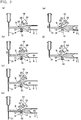
- Figs. 3(a) to 3(f) show concepts illustrating the operating steps of the injection device .
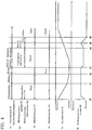
- Fig. 4 shows a time chart of the working statuses of the respective constituent instruments conformed to the operating steps.
- the pressing force of the holding pressure drive cylinder 24 is released and, in this state, the holding pressure plunger 22 is freed.
- the shutoff drive cylinder 14 is driven to bring the shutoff plunger 12 into a retracted state (open state).
- the injecting drive cylinder 5 (see Fig. 1 and Figs. 2(a), 2(b) ) is driven to pressurize the injection screw 2.
- the injecting drive cylinder 5 is in a state where it can inject the resin (a). Simultaneously with the injection of the resin into a preforming mold (mold), the holding pressure drive cylinder 24 is freed, charging of the resin into the holding pressure path 9 is also performed (b), the shutoff plunger 12 is opened (c), and the shutoff member 31 for the mold device is rendered open (d).
- the injection screw 2 is located at the backward movement end position (e), and the holding pressure plunger 22 is located at the forward movement end position (f) .
- the injecting drive cylinder 5 is driven to pressurize the injection screw 2 and move it forward.
- the resin in the resin path 6 flows into the holding pressure path 9 to push back the holding pressure plunger 22 (charging). Simultaneously, the resin begins to be charged into the mold.
- the resin in the resin path 6 flows into the holding pressure path 9 to push back the holding pressure plunger 22 further (charging), and the interior of the mold is filled with the resin, whereupon injection is completed.
- the driving position (pressurizing state) of the injecting drive cylinder 5 is held for a predetermined period of time, and pressurization by the injection screw 2 holds (maintains) the pressure of the resin in the resin path 6 and the holding pressure path 9 (primary holding pressure process).
- shutoff of the resin path 6 by the shutoff plunger 12 is released and, in this state, driving of the injecting drive cylinder 5 keeps the injection screw 2 pressurized to maintain the pressure of the resin in the resin path 6 and the holding pressure path 9.
- the resin is charged into the mold by the injecting drive cylinder 5
- the resin is flowed into the holding pressure path 9, and pressurization by the injection screw 2 is maintained to carry out holding pressure (dwelling) .
- the holding pressure drive cylinder 24 of a small size can be used.
- a configuration in which the resin is flowed into the holding pressure path 9 forcibly by control is not adopted.
- a negative pressure is suppressed, so that air bubbles, silver streaks or the like can be inhibited from occurring.
- the pressurizing state of the injecting drive cylinder 5 is held for a predetermined time, whereafter the injecting drive cylinder 5 is reduced in pressure, and the injection screw 2 makes a backward movement (a) .
- the holding pressure drive cylinder 24 begins to exert a pressing force, and its pressurization is held (b).
- the injection screw 2 begins to move backward (e), and the shutoff plunger 12 recedes to open the resin path 6. Then, the holding pressure plunger 22 moves forward by a predetermined amount to maintain the forward movement position (f).
- charging (metering) of the resin for next injection can be started immediately.
- the charging time can be ensured sufficiently, and the rotational speed of the injection screw 2 can be lowered.
- the barrel whose temperature is to be set can be lowered in temperature, and the occurrence of acetaldehyde can be decreased.
- the shutoff member 31 on the mold side is closed to shut off the path, and the pressing force of the holding pressure drive cylinder 24 is reduced, whereby the pressing force of the holding pressure plunger 22 is once released.
- the shutoff drive cylinder 14 is driven to retract the shutoff plunger 12, thereby releasing the shutoff of the resin path 6 (opening the resin path 6) .
- a pressing force is exerted again by the holding pressure drive cylinder 24 to move the holding pressure plunger 22 forward until its tip projects into the resin path 6 and discharge all the resin in the holding pressure path 9 to the resin path 6.
- the resin path 6 is closed with the shutoff plunger 12, whereupon the holding pressure (dwelling) of the resin path 6 and the holding pressure path 9 is continued using the holding pressure plunger 22.
- the shutoff member 31 on the mold side is closed, and the pressing force of the holding pressure plunger 22 is once released.
- the molten resin can be maintained in the optimum state, also at a time when the molded product is removed from the mold.
- shutoff by the shutoff plunger 12 is released to open the resin path 6, and the pressing force is exerted again on the holding pressure plunger 22 to move the holding pressure plunger 22 forward until its tip projects into the resin path 6, thereby discharging the resin.
- the holding pressure plunger 22 is moved forward until its tip projects into the resin path 6 to discharge all the resin in the holding pressure path 9 to the resin path 6.
- the present invention can be utilized in the industrial fields of injection devices and resin injection methods.
Landscapes
- Engineering & Computer Science (AREA)
- Mechanical Engineering (AREA)
- Manufacturing & Machinery (AREA)
- Injection Moulding Of Plastics Or The Like (AREA)
Claims (5)
- Procédé d'injection de résine pour injecter une résine depuis un cylindre d'injection (1) à travers un conduit de résine (6) jusqu'à une buse d'injection (3) et faire circuler la résine dans un conduit de maintien de pression (9) communiquant avec le conduit de résine (6) pour maintenir une pression de la résine dans le conduit de résine (6) et le conduit de maintien de pression (9), comprenant :- la mise sous pression de la résine dans le conduit de résine (6) au moyen du cylindre d'injection (1) pour maintenir la résine dans le conduit de résine (6) et le conduit de maintien de pression (9) ;- puis l'isolement du conduit de résine (6) par un moyen d'isolement (8) disposé entre le cylindre d'injection (1) et le conduit de maintien de pression (9),- la mise sous pression du conduit de maintien de pression (9) en faisant avancer un piston de maintien de pression (22) équipé d'un moyen de maintien de pression (10) dans le conduit de maintien de pression (9) pour effectuer le maintien de la pression du conduit de résine (6) et du conduit de maintien de pression (9),- l'isolement d'un conduit d'entrée pour la résine sur un côté moule par un organe d'isolement (31) et le relâchement de la pression du conduit de maintien de pression (9) une fois,- le relâchement de l'isolement du conduit de résine (6) en relâchant le moyen d'isolement (8), et- après le relâchement du moyen d'isolement (8), l'évacuation de toute la résine maintenue dans le conduit de maintien de pression (9) vers le conduit de résine (6) en déplaçant le piston de maintien de pression (22) jusqu'à une position d'extrémité de mouvement vers l'avant, dans laquelle le bout de celui-ci dépasse dans le conduit de résine (6) et recharger la résine dans le cylindre d'injection (1).
- Procédé d'injection de résine selon la revendication 1,
caractérisé en ce que- lorsque la pression dans le conduit de pression (6) doit être maintenue, le conduit de résine (6) est isolé par le moyen d'isolement (8) pour poursuivre le maintien de la résine dans le conduit de résine (6) et le conduit de maintien de pression (9),- puis, le conduit de résine (6) ayant été isolé, la force de pressage est exercée sur le moyen de maintien de pression (10), un conduit d'entrée pour la résine sur un côté moule est isolé, et la force de pressage sur le moyen de maintien de pression (10) est relâchée une fois, et- puis, l'isolement du conduit de résine (6) est relâché, et la force de pressage est de nouveau exercée sur le moyen de maintien de pression (10) pour évacuer toute la résine dans le conduit de maintien de pression (9) jusqu'au conduit de résine (6). - Procédé d'injection de résine selon l'une quelconque des revendications 1 ou 2, caractérisé en ce que- lorsque le conduit de résine (6) est isolé par le moyen d'isolement (8) après que la résine est maintenue dans le conduit de résine (6) et le conduit de maintien de pression (9) par la mise sous pression d'une vis d'injection (2) dans le cylindre d'injection (1), la vis d'injection (2) est actionnée en rotation dans une direction inverse pour charger la résine dans le cylindre d'injection (1).
- Dispositif d'injection pour exécuter le procédé d'injection de résine selon l'une quelconque des revendications 1 à 3, comprenant :- une buse d'injection (3) montée au niveau d'un côté moule sur une extrémité avant d'un cylindre d'injection (1), pour presser et injecter une résine, qui a été chargée dans le cylindre d'injection (1), à travers un conduit de résine (6) par une vis d'injection (2) ;- un moyen d'isolement (8) monté entre le cylindre d'injection (1) et la buse d'injection (3) et capable d'isoler le conduit de résine (6) dans un état d'isolement ;- un conduit de maintien de pression (9) formé dans un côté extrémité avant d'injection entre la buse d'injection (3) et le moyen d'isolement (8) et communiquant avec le conduit de résine (6) pour que la résine puisse s'écouler librement à l'intérieur de celui-ci ; et- un moyen de maintien de pression (10) ayant un piston de maintien de pression (22), qui est disposé en effectuant un mouvement de va-et-vient dans le conduit de maintien de pression (9), le moyen de maintien de pression (10) étant adapté pour fournir une force de pressage pour presser la résine dans le conduit de maintien de pression (9) vers le conduit de résine (6) en faisant avancer le piston de maintien de pression (22), et- dans lequel le piston de maintien de pression (22) est mobile dans une direction opposée à la direction de pressage par la résine s'écoulant dans le conduit de maintien de pression (9) lorsque la force de pressage est relâchée,- dans une position d'extrémité de mouvement vers l'avant du piston de maintien de pression (22), le bout du piston de maintien de pression (22) dépasse dans le conduit de résine (6),caractérisé en ce que- le moyen de maintien de pression (10) est adapté pour mettre sous pression le conduit de maintien de pression (9) en faisant avancer le piston de maintien de pression (22) dans le conduit de maintien de pression (9), lorsque le conduit de résine (6) est isolé par le moyen d'isolement (8), et pour mettre de nouveau sous pression le conduit de maintien de pression (9), lorsque l'isolement du conduit de résine (6) est relâché par le relâchement du moyen d'isolement (8) et un conduit d'entrée pour la résine sur un côté moule est isolé par un organe d'isolement (31).
- Dispositif d'injection selon la revendication 4,
caractérisé en ce que- dans la position d'extrémité de mouvement vers l'avant du piston de maintien de pression (22), le conduit de résine (6) sur le côté moule est fermé et le moyen d'isolement (8) est relâché dans l'état ouvert et le séjour de la résine dans le conduit de maintien de pression (9) est éliminé.
Applications Claiming Priority (2)
| Application Number | Priority Date | Filing Date | Title |
|---|---|---|---|
| JP2009268144A JP5535595B2 (ja) | 2009-11-25 | 2009-11-25 | 射出装置及び樹脂の射出方法 |
| PCT/JP2010/068085 WO2011065143A1 (fr) | 2009-11-25 | 2010-10-14 | Dispositif d'injection et procédé d'injection de résine |
Publications (3)
| Publication Number | Publication Date |
|---|---|
| EP2505334A1 EP2505334A1 (fr) | 2012-10-03 |
| EP2505334A4 EP2505334A4 (fr) | 2013-06-12 |
| EP2505334B1 true EP2505334B1 (fr) | 2018-12-05 |
Family
ID=44066247
Family Applications (1)
| Application Number | Title | Priority Date | Filing Date |
|---|---|---|---|
| EP10832990.5A Active EP2505334B1 (fr) | 2009-11-25 | 2010-10-14 | Dispositif d'injection et procédé d'injection de résine |
Country Status (7)
| Country | Link |
|---|---|
| US (2) | US20120217679A1 (fr) |
| EP (1) | EP2505334B1 (fr) |
| JP (1) | JP5535595B2 (fr) |
| CN (1) | CN102666065B (fr) |
| TR (1) | TR201900431T4 (fr) |
| TW (1) | TWI417182B (fr) |
| WO (1) | WO2011065143A1 (fr) |
Families Citing this family (2)
| Publication number | Priority date | Publication date | Assignee | Title |
|---|---|---|---|---|
| CN112092315A (zh) * | 2020-08-07 | 2020-12-18 | 昌盛达机械(浙江)有限公司 | 塑料注射成型机独立保压装置 |
| WO2023163208A1 (fr) * | 2022-02-28 | 2023-08-31 | 日精エー・エス・ビー機械株式会社 | Dispositif à demeure, dispositif d'injection et procédé d'injection pour matériau de résine |
Citations (1)
| Publication number | Priority date | Publication date | Assignee | Title |
|---|---|---|---|---|
| EP0198323A2 (fr) * | 1985-04-19 | 1986-10-22 | SANDRETTO INDUSTRIE S.p.A. | Dispositif d'injection de matière plastique |
Family Cites Families (13)
| Publication number | Priority date | Publication date | Assignee | Title |
|---|---|---|---|---|
| FR2325490A1 (fr) * | 1975-09-26 | 1977-04-22 | Creusot Loire | Dispositif de maintien de pression pour une machine de moulage par injection de matiere plastique et procede de moulage par injection correspondant |
| DE3307586A1 (de) * | 1982-03-19 | 1983-09-29 | Emhart Industries Inc., Farmington, Conn. | Spritzformanordnung und Verfahren zum Spritzgießen von Kunststoffteilen |
| US4632652A (en) * | 1985-05-01 | 1986-12-30 | Wedco Inc. | Draw-back valve assembly for an injection molding apparatus |
| JPH01241418A (ja) * | 1988-03-24 | 1989-09-26 | Japan Steel Works Ltd:The | 射出成形機の射出装置 |
| EP0389646B1 (fr) | 1988-10-13 | 1993-03-03 | Seiki Corporation Co. Ltd. | Procede et appareil de moulage par injection |
| US5071341A (en) | 1990-10-24 | 1991-12-10 | Hoover Universal, Inc. | Injection molding machine with pressure assist nozzle |
| DE4221423C2 (de) * | 1992-06-30 | 2002-06-20 | Sig Corpoplast Gmbh & Co Kg | Verfahren und Vorrichtung zum Herstellen von Gegenständen aus thermoplastischem Kunststoff durch Spritzgießen |
| US5509797A (en) * | 1993-09-30 | 1996-04-23 | Nissei Plastic Industrial Co., Ltd. | Injection apparatus possessing pressure holding device |
| JP2928750B2 (ja) * | 1995-09-27 | 1999-08-03 | 日精樹脂工業株式会社 | 射出成形における保圧方法 |
| DE19811273C2 (de) * | 1998-03-11 | 2000-01-27 | Mannesmann Ag | Verfahren und Vorrichtung zum Filtern von Kunststoffen in Spritzgießmaschinen |
| JP4516208B2 (ja) * | 2000-12-27 | 2010-08-04 | 日精エー・エス・ビー機械株式会社 | 射出装置及び射出成形方法 |
| JP2002240114A (ja) * | 2001-02-19 | 2002-08-28 | Nishikawa Kasei Co Ltd | 射出成形方法 |
| JP2003205530A (ja) * | 2002-01-10 | 2003-07-22 | Toshiba Mach Co Ltd | 射出成形機用ノズル及び射出成形方法 |
-
2009
- 2009-11-25 JP JP2009268144A patent/JP5535595B2/ja active Active
-
2010
- 2010-10-14 EP EP10832990.5A patent/EP2505334B1/fr active Active
- 2010-10-14 CN CN201080053530.2A patent/CN102666065B/zh active Active
- 2010-10-14 WO PCT/JP2010/068085 patent/WO2011065143A1/fr active Application Filing
- 2010-10-14 TR TR2019/00431T patent/TR201900431T4/tr unknown
- 2010-11-02 TW TW099137619A patent/TWI417182B/zh active
-
2012
- 2012-05-09 US US13/467,446 patent/US20120217679A1/en not_active Abandoned
-
2016
- 2016-04-21 US US15/134,591 patent/US10213947B2/en active Active
Patent Citations (1)
| Publication number | Priority date | Publication date | Assignee | Title |
|---|---|---|---|---|
| EP0198323A2 (fr) * | 1985-04-19 | 1986-10-22 | SANDRETTO INDUSTRIE S.p.A. | Dispositif d'injection de matière plastique |
Also Published As
| Publication number | Publication date |
|---|---|
| CN102666065A (zh) | 2012-09-12 |
| US20120217679A1 (en) | 2012-08-30 |
| US10213947B2 (en) | 2019-02-26 |
| JP2011110772A (ja) | 2011-06-09 |
| EP2505334A1 (fr) | 2012-10-03 |
| WO2011065143A1 (fr) | 2011-06-03 |
| TR201900431T4 (tr) | 2019-02-21 |
| CN102666065B (zh) | 2015-05-13 |
| TWI417182B (zh) | 2013-12-01 |
| EP2505334A4 (fr) | 2013-06-12 |
| JP5535595B2 (ja) | 2014-07-02 |
| TW201139109A (en) | 2011-11-16 |
| US20160297129A1 (en) | 2016-10-13 |
Similar Documents
| Publication | Publication Date | Title |
|---|---|---|
| US5512223A (en) | Apparatus and method for local pressurizing type injection molding | |
| KR100551949B1 (ko) | 금형장치에 의한 수지 성형품의 성형방법 | |
| US6267580B1 (en) | Micro injection molding machine | |
| US10213947B2 (en) | Injection device and resin injection method | |
| CN110315694B (zh) | 注射成型机 | |
| EP1829664A1 (fr) | Procede de moulage, machine de moulage et produit moule | |
| KR20060033017A (ko) | 성형방법, 퍼지방법 및 성형기 | |
| US3401426A (en) | Plastic injection molding machine | |
| CN106626220A (zh) | 一种注塑装置 | |
| US20130112782A1 (en) | Injection assembly | |
| TW201416217A (zh) | 射出成形機 | |
| US20140023744A1 (en) | Mold Assembly with Integrated Melting Device | |
| CN110385841A (zh) | 用于液压缸注塑机的低惯量射出机构 | |
| CN2887574Y (zh) | 改进注塑机注射保压装置结构 | |
| US20060240142A1 (en) | Clamping apparatus for injection molding machine | |
| GB2254283A (en) | Improvements in plasticising units for screw injection moulding machines | |
| KR20050042723A (ko) | 금속재료의 사출장치와 사출성형방법 | |
| JPH0397517A (ja) | プリプラ式射出成形機 | |
| CN103895198A (zh) | 一种卧式双缸注射注塑装置 | |
| CN106626320A (zh) | 一种热熔装置 | |
| JP2002137251A (ja) | 射出成形機 | |
| CN201776888U (zh) | 用于注塑机的注射装置 | |
| CN106626235A (zh) | 一种注塑胶成型装置 | |
| CN113459384A (zh) | 注射成型机、注射成型系统 | |
| CN106626271A (zh) | 一种注塑成型模具 |
Legal Events
| Date | Code | Title | Description |
|---|---|---|---|
| PUAI | Public reference made under article 153(3) epc to a published international application that has entered the european phase |
Free format text: ORIGINAL CODE: 0009012 |
|
| 17P | Request for examination filed |
Effective date: 20120413 |
|
| AK | Designated contracting states |
Kind code of ref document: A1 Designated state(s): AL AT BE BG CH CY CZ DE DK EE ES FI FR GB GR HR HU IE IS IT LI LT LU LV MC MK MT NL NO PL PT RO RS SE SI SK SM TR |
|
| DAX | Request for extension of the european patent (deleted) | ||
| A4 | Supplementary search report drawn up and despatched |
Effective date: 20130513 |
|
| RIC1 | Information provided on ipc code assigned before grant |
Ipc: B29C 45/57 20060101AFI20130506BHEP Ipc: B29C 45/50 20060101ALI20130506BHEP Ipc: B29C 45/54 20060101ALI20130506BHEP |
|
| RAP1 | Party data changed (applicant data changed or rights of an application transferred) |
Owner name: NISSEI ASB MACHINE CO., LTD. |
|
| 17Q | First examination report despatched |
Effective date: 20160902 |
|
| STAA | Information on the status of an ep patent application or granted ep patent |
Free format text: STATUS: EXAMINATION IS IN PROGRESS |
|
| RIC1 | Information provided on ipc code assigned before grant |
Ipc: B29C 45/50 20060101ALI20180517BHEP Ipc: B29B 11/08 20060101ALN20180517BHEP Ipc: B29C 45/54 20060101ALI20180517BHEP Ipc: B29C 45/57 20060101AFI20180517BHEP |
|
| GRAP | Despatch of communication of intention to grant a patent |
Free format text: ORIGINAL CODE: EPIDOSNIGR1 |
|
| STAA | Information on the status of an ep patent application or granted ep patent |
Free format text: STATUS: GRANT OF PATENT IS INTENDED |
|
| INTG | Intention to grant announced |
Effective date: 20180720 |
|
| GRAS | Grant fee paid |
Free format text: ORIGINAL CODE: EPIDOSNIGR3 |
|
| GRAA | (expected) grant |
Free format text: ORIGINAL CODE: 0009210 |
|
| GRAA | (expected) grant |
Free format text: ORIGINAL CODE: 0009210 |
|
| STAA | Information on the status of an ep patent application or granted ep patent |
Free format text: STATUS: THE PATENT HAS BEEN GRANTED |
|
| AK | Designated contracting states |
Kind code of ref document: B1 Designated state(s): AL AT BE BG CH CY CZ DE DK EE ES FI FR GB GR HR HU IE IS IT LI LT LU LV MC MK MT NL NO PL PT RO RS SE SI SK SM TR |
|
| REG | Reference to a national code |
Ref country code: GB Ref legal event code: FG4D |
|
| REG | Reference to a national code |
Ref country code: CH Ref legal event code: EP |
|
| REG | Reference to a national code |
Ref country code: AT Ref legal event code: REF Ref document number: 1072483 Country of ref document: AT Kind code of ref document: T Effective date: 20181215 |
|
| REG | Reference to a national code |
Ref country code: IE Ref legal event code: FG4D |
|
| REG | Reference to a national code |
Ref country code: DE Ref legal event code: R096 Ref document number: 602010055687 Country of ref document: DE |
|
| REG | Reference to a national code |
Ref country code: NL Ref legal event code: MP Effective date: 20181205 |
|
| REG | Reference to a national code |
Ref country code: AT Ref legal event code: MK05 Ref document number: 1072483 Country of ref document: AT Kind code of ref document: T Effective date: 20181205 |
|
| REG | Reference to a national code |
Ref country code: LT Ref legal event code: MG4D |
|
| PG25 | Lapsed in a contracting state [announced via postgrant information from national office to epo] |
Ref country code: ES Free format text: LAPSE BECAUSE OF FAILURE TO SUBMIT A TRANSLATION OF THE DESCRIPTION OR TO PAY THE FEE WITHIN THE PRESCRIBED TIME-LIMIT Effective date: 20181205 Ref country code: LV Free format text: LAPSE BECAUSE OF FAILURE TO SUBMIT A TRANSLATION OF THE DESCRIPTION OR TO PAY THE FEE WITHIN THE PRESCRIBED TIME-LIMIT Effective date: 20181205 Ref country code: BG Free format text: LAPSE BECAUSE OF FAILURE TO SUBMIT A TRANSLATION OF THE DESCRIPTION OR TO PAY THE FEE WITHIN THE PRESCRIBED TIME-LIMIT Effective date: 20190305 Ref country code: FI Free format text: LAPSE BECAUSE OF FAILURE TO SUBMIT A TRANSLATION OF THE DESCRIPTION OR TO PAY THE FEE WITHIN THE PRESCRIBED TIME-LIMIT Effective date: 20181205 Ref country code: HR Free format text: LAPSE BECAUSE OF FAILURE TO SUBMIT A TRANSLATION OF THE DESCRIPTION OR TO PAY THE FEE WITHIN THE PRESCRIBED TIME-LIMIT Effective date: 20181205 Ref country code: AT Free format text: LAPSE BECAUSE OF FAILURE TO SUBMIT A TRANSLATION OF THE DESCRIPTION OR TO PAY THE FEE WITHIN THE PRESCRIBED TIME-LIMIT Effective date: 20181205 Ref country code: LT Free format text: LAPSE BECAUSE OF FAILURE TO SUBMIT A TRANSLATION OF THE DESCRIPTION OR TO PAY THE FEE WITHIN THE PRESCRIBED TIME-LIMIT Effective date: 20181205 Ref country code: NO Free format text: LAPSE BECAUSE OF FAILURE TO SUBMIT A TRANSLATION OF THE DESCRIPTION OR TO PAY THE FEE WITHIN THE PRESCRIBED TIME-LIMIT Effective date: 20190305 |
|
| PG25 | Lapsed in a contracting state [announced via postgrant information from national office to epo] |
Ref country code: RS Free format text: LAPSE BECAUSE OF FAILURE TO SUBMIT A TRANSLATION OF THE DESCRIPTION OR TO PAY THE FEE WITHIN THE PRESCRIBED TIME-LIMIT Effective date: 20181205 Ref country code: GR Free format text: LAPSE BECAUSE OF FAILURE TO SUBMIT A TRANSLATION OF THE DESCRIPTION OR TO PAY THE FEE WITHIN THE PRESCRIBED TIME-LIMIT Effective date: 20190306 Ref country code: AL Free format text: LAPSE BECAUSE OF FAILURE TO SUBMIT A TRANSLATION OF THE DESCRIPTION OR TO PAY THE FEE WITHIN THE PRESCRIBED TIME-LIMIT Effective date: 20181205 Ref country code: SE Free format text: LAPSE BECAUSE OF FAILURE TO SUBMIT A TRANSLATION OF THE DESCRIPTION OR TO PAY THE FEE WITHIN THE PRESCRIBED TIME-LIMIT Effective date: 20181205 |
|
| PG25 | Lapsed in a contracting state [announced via postgrant information from national office to epo] |
Ref country code: NL Free format text: LAPSE BECAUSE OF FAILURE TO SUBMIT A TRANSLATION OF THE DESCRIPTION OR TO PAY THE FEE WITHIN THE PRESCRIBED TIME-LIMIT Effective date: 20181205 |
|
| PG25 | Lapsed in a contracting state [announced via postgrant information from national office to epo] |
Ref country code: CZ Free format text: LAPSE BECAUSE OF FAILURE TO SUBMIT A TRANSLATION OF THE DESCRIPTION OR TO PAY THE FEE WITHIN THE PRESCRIBED TIME-LIMIT Effective date: 20181205 Ref country code: PT Free format text: LAPSE BECAUSE OF FAILURE TO SUBMIT A TRANSLATION OF THE DESCRIPTION OR TO PAY THE FEE WITHIN THE PRESCRIBED TIME-LIMIT Effective date: 20190405 Ref country code: PL Free format text: LAPSE BECAUSE OF FAILURE TO SUBMIT A TRANSLATION OF THE DESCRIPTION OR TO PAY THE FEE WITHIN THE PRESCRIBED TIME-LIMIT Effective date: 20181205 |
|
| PG25 | Lapsed in a contracting state [announced via postgrant information from national office to epo] |
Ref country code: SK Free format text: LAPSE BECAUSE OF FAILURE TO SUBMIT A TRANSLATION OF THE DESCRIPTION OR TO PAY THE FEE WITHIN THE PRESCRIBED TIME-LIMIT Effective date: 20181205 Ref country code: IS Free format text: LAPSE BECAUSE OF FAILURE TO SUBMIT A TRANSLATION OF THE DESCRIPTION OR TO PAY THE FEE WITHIN THE PRESCRIBED TIME-LIMIT Effective date: 20190405 Ref country code: SM Free format text: LAPSE BECAUSE OF FAILURE TO SUBMIT A TRANSLATION OF THE DESCRIPTION OR TO PAY THE FEE WITHIN THE PRESCRIBED TIME-LIMIT Effective date: 20181205 Ref country code: EE Free format text: LAPSE BECAUSE OF FAILURE TO SUBMIT A TRANSLATION OF THE DESCRIPTION OR TO PAY THE FEE WITHIN THE PRESCRIBED TIME-LIMIT Effective date: 20181205 Ref country code: RO Free format text: LAPSE BECAUSE OF FAILURE TO SUBMIT A TRANSLATION OF THE DESCRIPTION OR TO PAY THE FEE WITHIN THE PRESCRIBED TIME-LIMIT Effective date: 20181205 |
|
| REG | Reference to a national code |
Ref country code: DE Ref legal event code: R097 Ref document number: 602010055687 Country of ref document: DE |
|
| PLBE | No opposition filed within time limit |
Free format text: ORIGINAL CODE: 0009261 |
|
| STAA | Information on the status of an ep patent application or granted ep patent |
Free format text: STATUS: NO OPPOSITION FILED WITHIN TIME LIMIT |
|
| PG25 | Lapsed in a contracting state [announced via postgrant information from national office to epo] |
Ref country code: SI Free format text: LAPSE BECAUSE OF FAILURE TO SUBMIT A TRANSLATION OF THE DESCRIPTION OR TO PAY THE FEE WITHIN THE PRESCRIBED TIME-LIMIT Effective date: 20181205 Ref country code: DK Free format text: LAPSE BECAUSE OF FAILURE TO SUBMIT A TRANSLATION OF THE DESCRIPTION OR TO PAY THE FEE WITHIN THE PRESCRIBED TIME-LIMIT Effective date: 20181205 |
|
| 26N | No opposition filed |
Effective date: 20190906 |
|
| PG25 | Lapsed in a contracting state [announced via postgrant information from national office to epo] |
Ref country code: MC Free format text: LAPSE BECAUSE OF FAILURE TO SUBMIT A TRANSLATION OF THE DESCRIPTION OR TO PAY THE FEE WITHIN THE PRESCRIBED TIME-LIMIT Effective date: 20181205 |
|
| REG | Reference to a national code |
Ref country code: CH Ref legal event code: PL |
|
| PG25 | Lapsed in a contracting state [announced via postgrant information from national office to epo] |
Ref country code: LU Free format text: LAPSE BECAUSE OF NON-PAYMENT OF DUE FEES Effective date: 20191014 Ref country code: CH Free format text: LAPSE BECAUSE OF NON-PAYMENT OF DUE FEES Effective date: 20191031 Ref country code: LI Free format text: LAPSE BECAUSE OF NON-PAYMENT OF DUE FEES Effective date: 20191031 |
|
| REG | Reference to a national code |
Ref country code: BE Ref legal event code: MM Effective date: 20191031 |
|
| PG25 | Lapsed in a contracting state [announced via postgrant information from national office to epo] |
Ref country code: BE Free format text: LAPSE BECAUSE OF NON-PAYMENT OF DUE FEES Effective date: 20191031 |
|
| PG25 | Lapsed in a contracting state [announced via postgrant information from national office to epo] |
Ref country code: IE Free format text: LAPSE BECAUSE OF NON-PAYMENT OF DUE FEES Effective date: 20191014 |
|
| PG25 | Lapsed in a contracting state [announced via postgrant information from national office to epo] |
Ref country code: CY Free format text: LAPSE BECAUSE OF FAILURE TO SUBMIT A TRANSLATION OF THE DESCRIPTION OR TO PAY THE FEE WITHIN THE PRESCRIBED TIME-LIMIT Effective date: 20181205 |
|
| PG25 | Lapsed in a contracting state [announced via postgrant information from national office to epo] |
Ref country code: HU Free format text: LAPSE BECAUSE OF FAILURE TO SUBMIT A TRANSLATION OF THE DESCRIPTION OR TO PAY THE FEE WITHIN THE PRESCRIBED TIME-LIMIT; INVALID AB INITIO Effective date: 20101014 Ref country code: MT Free format text: LAPSE BECAUSE OF FAILURE TO SUBMIT A TRANSLATION OF THE DESCRIPTION OR TO PAY THE FEE WITHIN THE PRESCRIBED TIME-LIMIT Effective date: 20181205 |
|
| PG25 | Lapsed in a contracting state [announced via postgrant information from national office to epo] |
Ref country code: MK Free format text: LAPSE BECAUSE OF FAILURE TO SUBMIT A TRANSLATION OF THE DESCRIPTION OR TO PAY THE FEE WITHIN THE PRESCRIBED TIME-LIMIT Effective date: 20181205 |
|
| PGFP | Annual fee paid to national office [announced via postgrant information from national office to epo] |
Ref country code: IT Payment date: 20230913 Year of fee payment: 14 Ref country code: GB Payment date: 20230831 Year of fee payment: 14 |
|
| PGFP | Annual fee paid to national office [announced via postgrant information from national office to epo] |
Ref country code: FR Payment date: 20230911 Year of fee payment: 14 |
|
| PGFP | Annual fee paid to national office [announced via postgrant information from national office to epo] |
Ref country code: TR Payment date: 20231012 Year of fee payment: 14 Ref country code: DE Payment date: 20230830 Year of fee payment: 14 |