EP2505334B1 - Injection device and resin injection method - Google Patents
Injection device and resin injection method Download PDFInfo
- Publication number
- EP2505334B1 EP2505334B1 EP10832990.5A EP10832990A EP2505334B1 EP 2505334 B1 EP2505334 B1 EP 2505334B1 EP 10832990 A EP10832990 A EP 10832990A EP 2505334 B1 EP2505334 B1 EP 2505334B1
- Authority
- EP
- European Patent Office
- Prior art keywords
- resin
- path
- holding pressure
- injection
- shutoff
- Prior art date
- Legal status (The legal status is an assumption and is not a legal conclusion. Google has not performed a legal analysis and makes no representation as to the accuracy of the status listed.)
- Active
Links
- 239000011347 resin Substances 0.000 title claims description 189
- 229920005989 resin Polymers 0.000 title claims description 189
- 238000002347 injection Methods 0.000 title claims description 127
- 239000007924 injection Substances 0.000 title claims description 127
- 238000000034 method Methods 0.000 title claims description 19
- 238000003825 pressing Methods 0.000 claims description 23
- 230000033001 locomotion Effects 0.000 claims description 18
- 238000007599 discharging Methods 0.000 claims description 2
- 239000000463 material Substances 0.000 description 7
- 239000012778 molding material Substances 0.000 description 3
- IKHGUXGNUITLKF-UHFFFAOYSA-N Acetaldehyde Chemical compound CC=O IKHGUXGNUITLKF-UHFFFAOYSA-N 0.000 description 2
- 235000013361 beverage Nutrition 0.000 description 2
- 238000001746 injection moulding Methods 0.000 description 2
- BQCADISMDOOEFD-UHFFFAOYSA-N Silver Chemical compound [Ag] BQCADISMDOOEFD-UHFFFAOYSA-N 0.000 description 1
- 238000000071 blow moulding Methods 0.000 description 1
- 235000012206 bottled water Nutrition 0.000 description 1
- 239000000470 constituent Substances 0.000 description 1
- 238000001816 cooling Methods 0.000 description 1
- 230000003247 decreasing effect Effects 0.000 description 1
- 230000007812 deficiency Effects 0.000 description 1
- 239000003651 drinking water Substances 0.000 description 1
- 230000000694 effects Effects 0.000 description 1
- 238000009434 installation Methods 0.000 description 1
- 238000004519 manufacturing process Methods 0.000 description 1
- 238000000465 moulding Methods 0.000 description 1
- 229910052709 silver Inorganic materials 0.000 description 1
- 239000004332 silver Substances 0.000 description 1
Images

Classifications
-
- B—PERFORMING OPERATIONS; TRANSPORTING
- B29—WORKING OF PLASTICS; WORKING OF SUBSTANCES IN A PLASTIC STATE IN GENERAL
- B29C—SHAPING OR JOINING OF PLASTICS; SHAPING OF MATERIAL IN A PLASTIC STATE, NOT OTHERWISE PROVIDED FOR; AFTER-TREATMENT OF THE SHAPED PRODUCTS, e.g. REPAIRING
- B29C45/00—Injection moulding, i.e. forcing the required volume of moulding material through a nozzle into a closed mould; Apparatus therefor
- B29C45/17—Component parts, details or accessories; Auxiliary operations
- B29C45/46—Means for plasticising or homogenising the moulding material or forcing it into the mould
- B29C45/57—Exerting after-pressure on the moulding material
-
- B—PERFORMING OPERATIONS; TRANSPORTING
- B29—WORKING OF PLASTICS; WORKING OF SUBSTANCES IN A PLASTIC STATE IN GENERAL
- B29B—PREPARATION OR PRETREATMENT OF THE MATERIAL TO BE SHAPED; MAKING GRANULES OR PREFORMS; RECOVERY OF PLASTICS OR OTHER CONSTITUENTS OF WASTE MATERIAL CONTAINING PLASTICS
- B29B11/00—Making preforms
- B29B11/06—Making preforms by moulding the material
- B29B11/08—Injection moulding
-
- B—PERFORMING OPERATIONS; TRANSPORTING
- B29—WORKING OF PLASTICS; WORKING OF SUBSTANCES IN A PLASTIC STATE IN GENERAL
- B29C—SHAPING OR JOINING OF PLASTICS; SHAPING OF MATERIAL IN A PLASTIC STATE, NOT OTHERWISE PROVIDED FOR; AFTER-TREATMENT OF THE SHAPED PRODUCTS, e.g. REPAIRING
- B29C45/00—Injection moulding, i.e. forcing the required volume of moulding material through a nozzle into a closed mould; Apparatus therefor
- B29C45/17—Component parts, details or accessories; Auxiliary operations
- B29C45/46—Means for plasticising or homogenising the moulding material or forcing it into the mould
- B29C45/47—Means for plasticising or homogenising the moulding material or forcing it into the mould using screws
- B29C45/50—Axially movable screw
-
- B—PERFORMING OPERATIONS; TRANSPORTING
- B29—WORKING OF PLASTICS; WORKING OF SUBSTANCES IN A PLASTIC STATE IN GENERAL
- B29C—SHAPING OR JOINING OF PLASTICS; SHAPING OF MATERIAL IN A PLASTIC STATE, NOT OTHERWISE PROVIDED FOR; AFTER-TREATMENT OF THE SHAPED PRODUCTS, e.g. REPAIRING
- B29C45/00—Injection moulding, i.e. forcing the required volume of moulding material through a nozzle into a closed mould; Apparatus therefor
- B29C45/17—Component parts, details or accessories; Auxiliary operations
- B29C45/46—Means for plasticising or homogenising the moulding material or forcing it into the mould
- B29C45/53—Means for plasticising or homogenising the moulding material or forcing it into the mould using injection ram or piston
- B29C45/54—Means for plasticising or homogenising the moulding material or forcing it into the mould using injection ram or piston and plasticising screw
-
- B—PERFORMING OPERATIONS; TRANSPORTING
- B29—WORKING OF PLASTICS; WORKING OF SUBSTANCES IN A PLASTIC STATE IN GENERAL
- B29K—INDEXING SCHEME ASSOCIATED WITH SUBCLASSES B29B, B29C OR B29D, RELATING TO MOULDING MATERIALS OR TO MATERIALS FOR MOULDS, REINFORCEMENTS, FILLERS OR PREFORMED PARTS, e.g. INSERTS
- B29K2067/00—Use of polyesters or derivatives thereof, as moulding material
- B29K2067/003—PET, i.e. poylethylene terephthalate
-
- B—PERFORMING OPERATIONS; TRANSPORTING
- B29—WORKING OF PLASTICS; WORKING OF SUBSTANCES IN A PLASTIC STATE IN GENERAL
- B29K—INDEXING SCHEME ASSOCIATED WITH SUBCLASSES B29B, B29C OR B29D, RELATING TO MOULDING MATERIALS OR TO MATERIALS FOR MOULDS, REINFORCEMENTS, FILLERS OR PREFORMED PARTS, e.g. INSERTS
- B29K2105/00—Condition, form or state of moulded material or of the material to be shaped
- B29K2105/25—Solid
- B29K2105/253—Preform
-
- B—PERFORMING OPERATIONS; TRANSPORTING
- B29—WORKING OF PLASTICS; WORKING OF SUBSTANCES IN A PLASTIC STATE IN GENERAL
- B29L—INDEXING SCHEME ASSOCIATED WITH SUBCLASS B29C, RELATING TO PARTICULAR ARTICLES
- B29L2031/00—Other particular articles
- B29L2031/712—Containers; Packaging elements or accessories, Packages
- B29L2031/7158—Bottles
Definitions
- the present invention also relates to a resin injection method for injecting the resin, with the pressure of the resin being maintained in the resin path of the injection nozzle, according to claim 1.
- This invention relates to an injection device equipped with a means for maintaining the pressure of a resin in a resin path of an injection nozzle, according to claim 4.
- PET bottles for example, are frequently used as bottles for potable water, etc.
- the PET bottle is produced in the shape of a bottle by forming a test tube-shaped preform with the use of an injection molding device (injection device), and blow-molding the preform.
- injection device injection molding device
- an in-line screw type injection device is known for example from JP-A-9-8570 .
- a metering step of supplying a new resin material into an injection cylinder, an injection step of extruding and charging the resin material into a mold, and a holding pressure (dwelling) step of maintaining the pressure of the resin material within a resin path are repeatedly performed.
- the injection step and the holding pressure step are completed and before the injection step of a next cycle is started, cooling of a molded product, mold opening, withdrawal of the molded product, and mold closing are carried out. During this process, the metering step is performed.
- the resin path is closed by a dedicated plunger or the like to maintain the pressure of the resin material. During this period, an injection screw is moved backward, and a new resin material is supplied into the injection cylinder.
- the resin path is pressurized by a holding pressure mechanism.
- the resin has flowed into the resin charging site of the holding pressure mechanism (the holding pressure mechanism and the resin are in contact). If the resin flowing into the holding pressure mechanism (charging site) resides there, various deficiencies such as burn marks are induced. Thus, the resin flowing into the holding pressure mechanism needs to be discharged into the resin path to eliminate residence.
- Patent US-A-6017210 discloses an injection method and device of the related art.
- the pressure holding means comprises a plunger, the forward movement of which is limited to prevent its projection into the holding pressure path. Similar devices are known from JP-A-01-241418 and GB-A-2116903 .
- the present invention has been accomplished in the light of the above-mentioned circumstances. It is an object of the present invention to provide an injection device and a resin injection method which can reliably eliminate the residence of the resin even with the use of an inexpensive holding pressure mechanism.
- the object is solved according to the present invention by an injection method according to any one of claims 1-3 and a device according to any one of claims 4-5.
- the present invention makes it possible to provide an injection device and a resin injection method which can reliably eliminate the residence of a resin, even with the use of a holding pressure mechanism which is not extensive and not expensive.
- the configuration of the injection device according to the embodiment of the present invention will be described based on Fig. 1 and Figs. 2(a), 2(b) .
- the illustrated injection device is intended to be applied, for example, as an injection device for forming a preform in the shape of a test tube during the process for preparing a beverage bottle from a resin.
- An injection-molded product is not limited to the preform, and the injection device of the present invention can be used as an injection device for obtaining various molded products.
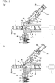
- Figs. 1 , 2(a) and 2(b) show the sectional state of a leading end portion (an injection nozzle portion) of the injection device according to the embodiment of the present invention, in which Fig. 1 shows a state where a resin is injected, Fig. 2(a) shows a state where a resin path is closed to maintain the pressure of the resin, and Fig. 2(b) shows a state where the resin path is opened, and the pressure of the resin is maintained.
- a hopper for supplying a molding material, a drive device for rotationally driving an injection screw, and so on are provided, although these members are not shown.
- an injection screw 2 is supported inside an injection cylinder 1, and an injection nozzle 3 is mounted at the front end of the injection cylinder 1.
- a hopper for supplying a molding material is connected to the injection cylinder 1, and the molding material is supplied into the injection cylinder 1.
- a screw head 4 is provided at the front end of the injection screw 2, and the injection screw 2 is rotationally driven to plasticize the resin heated and melted within the injection cylinder 1.
- the injection screw 2 is moved backward.
- an injecting drive cylinder 5 is driven to move the injection screw 2 forward, performing the injection of the molten resin.
- a resin path 6 is formed inside the injection cylinder 1, and the injection nozzle 3 is connected to the front end of the resin path 6.
- the injection nozzle 3 is connected to a mold via a hot runner (not shown) .
- a shutoff device 8, as a shutoff means, is connected in an integral state to the injection nozzle 3, and the resin path 6 is free to be shut off by the shutoff device 8.
- a holding pressure path 9 communicating with the resin path 6 is formed.
- the holding pressure path 9 is formed to be inclined rearwardly (rightwardly in the drawings) with respect to the resin path 6, and the resin charged into the holding pressure path 9 and the resin path 6 has its pressure maintained by a holding pressure device 10.
- the shutoff device 8 is equipped with a shutoff cylinder 11 integrated with the injection cylinder 1, and a piston rod portion 13 of a shutoff plunger 12 is reciprocatably supported in the shutoff cylinder 11.
- a shutoff drive cylinder 14 is connected to the shutoff cylinder 11, and a shutoff piston 15 is reciprocatably supported in the shutoff drive cylinder 14.
- the shutoff drive cylinder 14 is supplied with a pressure oil, and the pressure oil is discharged from the shutoff drive cylinder 14, whereby the shutoff piston 15 is driven to reciprocate.
- the shutoff piston 15 of the shutoff drive cylinder 14 is connected to the piston rod portion 13 of the shutoff plunger 12, and the shutoff plunger 12 is reciprocated (moved forward and backward) by the driving of the shutoff drive cylinder 14 via the shutoff piston 15 and the piston rod portion 13. As shown in Figs. 2(a), 2(b) , the shutoff plunger 12 moves forward (makes a closing motion), thereby shutting off (closing) the resin path 6 forward of the screw head 4.
- the holding pressure device 10 is equipped with a holding pressure cylinder 21 integrated with the injection cylinder 1, and a piston rod portion 23 of a holding pressure plunger 22 is reciprocatably supported in the holding pressure cylinder 21.
- the holding pressure plunger 22 is disposed in the holding pressure path 9 so as to be capable of reciprocating (movable backwardly and forwardly) .
- a tip portion of the holding pressure plunger 22 when located at a forward movement end position is disposed to project into the resin path 6.
- a holding pressure drive cylinder 24 is connected to the holding pressure cylinder 21, and a holding pressure piston 25 is supported in the holding pressure drive cylinder 24 so as to be drivable in a reciprocating manner .
- a pressure oil is supplied to the holding pressure drive cylinder 24 to impart a pressing force to the holding pressure piston 25, while a discharge path for the pressure oil is opened in the holding pressure drive cylinder 24 to release the pressing force by the holding pressure piston 25.
- the holding pressure piston 25 of the holding pressure drive cylinder 24 is connected to the piston rod portion 23 of the holding pressure plunger 22, and the driving of the holding pressure drive cylinder 24 exerts the pressing force on the holding pressure plunger 22 via the holding pressure piston 25 and the piston rod portion 23.
- Figs. 2 (a), 2 (b) when the pressing force is applied until the holding pressure plunger 22 is moved to the forward movement end position, the tip portion of the holding pressure plunger 22 is projected into the resin path 6.
- the holding pressure plunger 22 is pushed by the resin from the resin path 6 and moved backward, with the result that the resin is charged into the holding pressure path 9.
- a mold device at the site of the leading end of the injection nozzle 3 is equipped with a shutoff member 31.
- the shutoff member 31 is opened and closed in a manner interlocked with a holding pressure motion for the resin (to be described later) at the completion of injection.
- a holding pressure motion for the resin to be described later
- the injecting drive cylinder 5 is driven, with the shutoff plunger 12 being open, to pressurize the injection screw 2.
- the holding pressure plunger 22 is moved backward under the pressure of the resin to flow the resin into the holding pressure path 9, and the resin in the resin path 6 is pressurized, as shown in Fig. 1 .
- primary holding pressure process is carried out.
- the shutoff plunger 12 is closed to pressurize the holding pressure plunger 22 and pressurize the resin in the resin path 6 and the holding pressure path 9. In this manner, secondary holding pressure process is performed.
- the shutoff plunger 12 is opened, and the holding pressure plunger 22 is moved forward until its tip projects into the resin path 6, whereby the resin in the holding pressure path 9 is discharged to the resin path 6 toward the injection screw 2 as compared with the shutoff plunger 12.
- the cylinder diameters of the holding pressure cylinder 21 and the holding pressure drive cylinder 24, and the diameters (shapes) of the piston rod portion 23 and the holding pressure piston 25 are set, as appropriate, such that the resin pressure during injection set by the injecting drive cylinder 5 and the set pressure of the holding pressure drive cylinder 24 when actuating the holding pressure mechanism are equal to each other. It is also possible to perform internal arithmetic from the screw diameter of the injection screw 2 of the injection cylinder 1, and adjust the pressure of the holding pressure drive cylinder 24 of the holding pressure device 10 to the same set pressure as that of the injection cylinder 1.
- the holding pressure path 9 is formed to be inclined rearwardly (rightwardly in the drawings) with respect to the resin path 6, and the holding pressure plunger 22 is disposed on the inclined holding pressure path 9.
- the holding pressure cylinder 21 and the holding pressure drive cylinder 24 are disposed to be inclined with respect to a direction perpendicular to the injection cylinder 1.
- the device is not upsized, and the injection device equipped with the holding pressure cylinder 21 and the holding pressure drive cylinder 24 can be installed in a limited space. Consequently, the injection device has a structure which facilitates its application, for example, as an injection device for forming a test tube-shaped preform during the process of preparing a beverage bottle from a resin.
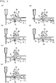
- Figs. 3(a) to 3(f) show concepts illustrating the operating steps of the injection device .
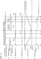
- Fig. 4 shows a time chart of the working statuses of the respective constituent instruments conformed to the operating steps.
- the pressing force of the holding pressure drive cylinder 24 is released and, in this state, the holding pressure plunger 22 is freed.
- the shutoff drive cylinder 14 is driven to bring the shutoff plunger 12 into a retracted state (open state).
- the injecting drive cylinder 5 (see Fig. 1 and Figs. 2(a), 2(b) ) is driven to pressurize the injection screw 2.
- the injecting drive cylinder 5 is in a state where it can inject the resin (a). Simultaneously with the injection of the resin into a preforming mold (mold), the holding pressure drive cylinder 24 is freed, charging of the resin into the holding pressure path 9 is also performed (b), the shutoff plunger 12 is opened (c), and the shutoff member 31 for the mold device is rendered open (d).
- the injection screw 2 is located at the backward movement end position (e), and the holding pressure plunger 22 is located at the forward movement end position (f) .
- the injecting drive cylinder 5 is driven to pressurize the injection screw 2 and move it forward.
- the resin in the resin path 6 flows into the holding pressure path 9 to push back the holding pressure plunger 22 (charging). Simultaneously, the resin begins to be charged into the mold.
- the resin in the resin path 6 flows into the holding pressure path 9 to push back the holding pressure plunger 22 further (charging), and the interior of the mold is filled with the resin, whereupon injection is completed.
- the driving position (pressurizing state) of the injecting drive cylinder 5 is held for a predetermined period of time, and pressurization by the injection screw 2 holds (maintains) the pressure of the resin in the resin path 6 and the holding pressure path 9 (primary holding pressure process).
- shutoff of the resin path 6 by the shutoff plunger 12 is released and, in this state, driving of the injecting drive cylinder 5 keeps the injection screw 2 pressurized to maintain the pressure of the resin in the resin path 6 and the holding pressure path 9.
- the resin is charged into the mold by the injecting drive cylinder 5
- the resin is flowed into the holding pressure path 9, and pressurization by the injection screw 2 is maintained to carry out holding pressure (dwelling) .
- the holding pressure drive cylinder 24 of a small size can be used.
- a configuration in which the resin is flowed into the holding pressure path 9 forcibly by control is not adopted.
- a negative pressure is suppressed, so that air bubbles, silver streaks or the like can be inhibited from occurring.
- the pressurizing state of the injecting drive cylinder 5 is held for a predetermined time, whereafter the injecting drive cylinder 5 is reduced in pressure, and the injection screw 2 makes a backward movement (a) .
- the holding pressure drive cylinder 24 begins to exert a pressing force, and its pressurization is held (b).
- the injection screw 2 begins to move backward (e), and the shutoff plunger 12 recedes to open the resin path 6. Then, the holding pressure plunger 22 moves forward by a predetermined amount to maintain the forward movement position (f).
- charging (metering) of the resin for next injection can be started immediately.
- the charging time can be ensured sufficiently, and the rotational speed of the injection screw 2 can be lowered.
- the barrel whose temperature is to be set can be lowered in temperature, and the occurrence of acetaldehyde can be decreased.
- the shutoff member 31 on the mold side is closed to shut off the path, and the pressing force of the holding pressure drive cylinder 24 is reduced, whereby the pressing force of the holding pressure plunger 22 is once released.
- the shutoff drive cylinder 14 is driven to retract the shutoff plunger 12, thereby releasing the shutoff of the resin path 6 (opening the resin path 6) .
- a pressing force is exerted again by the holding pressure drive cylinder 24 to move the holding pressure plunger 22 forward until its tip projects into the resin path 6 and discharge all the resin in the holding pressure path 9 to the resin path 6.
- the resin path 6 is closed with the shutoff plunger 12, whereupon the holding pressure (dwelling) of the resin path 6 and the holding pressure path 9 is continued using the holding pressure plunger 22.
- the shutoff member 31 on the mold side is closed, and the pressing force of the holding pressure plunger 22 is once released.
- the molten resin can be maintained in the optimum state, also at a time when the molded product is removed from the mold.
- shutoff by the shutoff plunger 12 is released to open the resin path 6, and the pressing force is exerted again on the holding pressure plunger 22 to move the holding pressure plunger 22 forward until its tip projects into the resin path 6, thereby discharging the resin.
- the holding pressure plunger 22 is moved forward until its tip projects into the resin path 6 to discharge all the resin in the holding pressure path 9 to the resin path 6.
- the present invention can be utilized in the industrial fields of injection devices and resin injection methods.
Description
- The present invention also relates to a resin injection method for injecting the resin, with the pressure of the resin being maintained in the resin path of the injection nozzle, according to
claim 1. - This invention relates to an injection device equipped with a means for maintaining the pressure of a resin in a resin path of an injection nozzle, according to
claim 4. - PET bottles, for example, are frequently used as bottles for potable water, etc. The PET bottle is produced in the shape of a bottle by forming a test tube-shaped preform with the use of an injection molding device (injection device), and blow-molding the preform.
- As the injection device for forming the preform, an in-line screw type injection device is known for example from
JP-A-9-8570 - After the injection step and the holding pressure step are completed and before the injection step of a next cycle is started, cooling of a molded product, mold opening, withdrawal of the molded product, and mold closing are carried out. During this process, the metering step is performed. To carry out the molding cycle unerringly in a short period of time, in the holding pressure step, the resin path is closed by a dedicated plunger or the like to maintain the pressure of the resin material. During this period, an injection screw is moved backward, and a new resin material is supplied into the injection cylinder.
- With the hitherto known injection device, in case the pressure of the resin material is maintained, the resin path is pressurized by a holding pressure mechanism. In the holding pressure step for the resin material, therefore, the resin has flowed into the resin charging site of the holding pressure mechanism (the holding pressure mechanism and the resin are in contact). If the resin flowing into the holding pressure mechanism (charging site) resides there, various deficiencies such as burn marks are induced. Thus, the resin flowing into the holding pressure mechanism needs to be discharged into the resin path to eliminate residence.
- In the field of an injection machine equipped with the holding pressure mechanism, therefore, it is under consideration to discharge the resin for holding pressure reliably into the resin path for injection, without upsizing or complicating instruments. In the small-sized injection machine field, in particular, since the device is small in size, an installation space is limited, and a complicated mechanism cannot be adopted.
- Document
US-A-6017210 discloses an injection method and device of the related art. The pressure holding means comprises a plunger, the forward movement of which is limited to prevent its projection into the holding pressure path. Similar devices are known fromJP-A-01-241418 GB-A-2116903 - The present invention has been accomplished in the light of the above-mentioned circumstances. It is an object of the present invention to provide an injection device and a resin injection method which can reliably eliminate the residence of the resin even with the use of an inexpensive holding pressure mechanism.
- The object is solved according to the present invention by an injection method according to any one of claims 1-3 and a device according to any one of claims 4-5.
- The present invention makes it possible to provide an injection device and a resin injection method which can reliably eliminate the residence of a resin, even with the use of a holding pressure mechanism which is not extensive and not expensive.
-
- [
Fig. 1 ] is a sectional view showing essential parts of an injection device according to an embodiment of the present invention. - [
Figs. 2(a), 2(b) ] are sectional views showing the essential parts of the injection device according to the embodiment of the present invention. - [
Figs. 3(a) to 3(f) ] are explanation drawings showing the motions of the injection device. - [
Fig. 4 ] is a time chart showing changes in the motions over time. [Mode for Carrying Out the Invention] - The configuration of the injection device according to the embodiment of the present invention will be described based on
Fig. 1 andFigs. 2(a), 2(b) . The illustrated injection device is intended to be applied, for example, as an injection device for forming a preform in the shape of a test tube during the process for preparing a beverage bottle from a resin. An injection-molded product is not limited to the preform, and the injection device of the present invention can be used as an injection device for obtaining various molded products. -
Figs. 1 ,2(a) and 2(b) show the sectional state of a leading end portion (an injection nozzle portion) of the injection device according to the embodiment of the present invention, in whichFig. 1 shows a state where a resin is injected,Fig. 2(a) shows a state where a resin path is closed to maintain the pressure of the resin, andFig. 2(b) shows a state where the resin path is opened, and the pressure of the resin is maintained. Behind the injection nozzle, a hopper for supplying a molding material, a drive device for rotationally driving an injection screw, and so on are provided, although these members are not shown. - As shown in the drawings, an
injection screw 2 is supported inside aninjection cylinder 1, and aninjection nozzle 3 is mounted at the front end of theinjection cylinder 1. A hopper for supplying a molding material is connected to theinjection cylinder 1, and the molding material is supplied into theinjection cylinder 1. - A
screw head 4 is provided at the front end of theinjection screw 2, and theinjection screw 2 is rotationally driven to plasticize the resin heated and melted within theinjection cylinder 1. As the molten resin is charged ahead of thescrew head 4, theinjection screw 2 is moved backward. Upon completion of the charging of the molten resin, an injectingdrive cylinder 5 is driven to move theinjection screw 2 forward, performing the injection of the molten resin. - A
resin path 6 is formed inside theinjection cylinder 1, and theinjection nozzle 3 is connected to the front end of theresin path 6. Theinjection nozzle 3 is connected to a mold via a hot runner (not shown) . Ashutoff device 8, as a shutoff means, is connected in an integral state to theinjection nozzle 3, and theresin path 6 is free to be shut off by theshutoff device 8. At a site of theinjection nozzle 3 toward the leading end in the injection direction with respect to the shutoff device 8 (i.e., the site leftward of theshutoff device 8 in the drawings), aholding pressure path 9 communicating with theresin path 6 is formed. Theholding pressure path 9 is formed to be inclined rearwardly (rightwardly in the drawings) with respect to theresin path 6, and the resin charged into theholding pressure path 9 and theresin path 6 has its pressure maintained by aholding pressure device 10. - The
shutoff device 8 is equipped with ashutoff cylinder 11 integrated with theinjection cylinder 1, and apiston rod portion 13 of ashutoff plunger 12 is reciprocatably supported in theshutoff cylinder 11. Ashutoff drive cylinder 14 is connected to theshutoff cylinder 11, and ashutoff piston 15 is reciprocatably supported in theshutoff drive cylinder 14. Theshutoff drive cylinder 14 is supplied with a pressure oil, and the pressure oil is discharged from theshutoff drive cylinder 14, whereby theshutoff piston 15 is driven to reciprocate. - The
shutoff piston 15 of theshutoff drive cylinder 14 is connected to thepiston rod portion 13 of theshutoff plunger 12, and theshutoff plunger 12 is reciprocated (moved forward and backward) by the driving of theshutoff drive cylinder 14 via theshutoff piston 15 and thepiston rod portion 13. As shown inFigs. 2(a), 2(b) , the shutoff plunger 12 moves forward (makes a closing motion), thereby shutting off (closing) theresin path 6 forward of thescrew head 4. - The
holding pressure device 10 is equipped with aholding pressure cylinder 21 integrated with theinjection cylinder 1, and apiston rod portion 23 of aholding pressure plunger 22 is reciprocatably supported in theholding pressure cylinder 21. Theholding pressure plunger 22 is disposed in theholding pressure path 9 so as to be capable of reciprocating (movable backwardly and forwardly) . A tip portion of theholding pressure plunger 22 when located at a forward movement end position is disposed to project into theresin path 6. A holdingpressure drive cylinder 24 is connected to theholding pressure cylinder 21, and aholding pressure piston 25 is supported in the holdingpressure drive cylinder 24 so as to be drivable in a reciprocating manner . A pressure oil is supplied to the holdingpressure drive cylinder 24 to impart a pressing force to theholding pressure piston 25, while a discharge path for the pressure oil is opened in the holdingpressure drive cylinder 24 to release the pressing force by theholding pressure piston 25. - The
holding pressure piston 25 of the holdingpressure drive cylinder 24 is connected to thepiston rod portion 23 of theholding pressure plunger 22, and the driving of the holdingpressure drive cylinder 24 exerts the pressing force on theholding pressure plunger 22 via theholding pressure piston 25 and thepiston rod portion 23. As shown inFigs. 2 (a), 2 (b) , when the pressing force is applied until theholding pressure plunger 22 is moved to the forward movement end position, the tip portion of theholding pressure plunger 22 is projected into theresin path 6. When the pressing force by theholding pressure piston 25 is released, theholding pressure plunger 22 is pushed by the resin from theresin path 6 and moved backward, with the result that the resin is charged into theholding pressure path 9. - A mold device at the site of the leading end of the
injection nozzle 3 is equipped with ashutoff member 31. Theshutoff member 31 is opened and closed in a manner interlocked with a holding pressure motion for the resin (to be described later) at the completion of injection. By the action of thisshutoff member 31, the relation between the resin charged into the mold and the resin having its pressure maintained in theinjection nozzle 3 is cut off. - When the resin in the
resin path 6 is to have its pressure maintained in the above-mentioned injection device, the injectingdrive cylinder 5 is driven, with theshutoff plunger 12 being open, to pressurize theinjection screw 2. As a result, the holdingpressure plunger 22 is moved backward under the pressure of the resin to flow the resin into the holdingpressure path 9, and the resin in theresin path 6 is pressurized, as shown inFig. 1 . In this manner, primary holding pressure process is carried out. Then, as shown inFig. 2 (a) , theshutoff plunger 12 is closed to pressurize the holdingpressure plunger 22 and pressurize the resin in theresin path 6 and the holdingpressure path 9. In this manner, secondary holding pressure process is performed. Finally, as shown inFig. 2(b) , theshutoff plunger 12 is opened, and the holdingpressure plunger 22 is moved forward until its tip projects into theresin path 6, whereby the resin in the holdingpressure path 9 is discharged to theresin path 6 toward theinjection screw 2 as compared with theshutoff plunger 12. - With the above-described injection device, the cylinder diameters of the holding
pressure cylinder 21 and the holdingpressure drive cylinder 24, and the diameters (shapes) of thepiston rod portion 23 and the holdingpressure piston 25 are set, as appropriate, such that the resin pressure during injection set by the injectingdrive cylinder 5 and the set pressure of the holdingpressure drive cylinder 24 when actuating the holding pressure mechanism are equal to each other. It is also possible to perform internal arithmetic from the screw diameter of theinjection screw 2 of theinjection cylinder 1, and adjust the pressure of the holdingpressure drive cylinder 24 of the holdingpressure device 10 to the same set pressure as that of theinjection cylinder 1. - The holding
pressure path 9 is formed to be inclined rearwardly (rightwardly in the drawings) with respect to theresin path 6, and the holdingpressure plunger 22 is disposed on the inclinedholding pressure path 9. Thus, the holdingpressure cylinder 21 and the holdingpressure drive cylinder 24 are disposed to be inclined with respect to a direction perpendicular to theinjection cylinder 1. Hence, it is minimally likely for the holdingpressure cylinder 21 and the holdingpressure drive cylinder 24 to interfere with surrounding instruments such as a cover. As a result, the device is not upsized, and the injection device equipped with the holdingpressure cylinder 21 and the holdingpressure drive cylinder 24 can be installed in a limited space. Consequently, the injection device has a structure which facilitates its application, for example, as an injection device for forming a test tube-shaped preform during the process of preparing a beverage bottle from a resin. - The motions of the above-described injection device will be explained concretely based on
Figs. 3(a) to 3(f) andFig. 4 . -
Figs. 3(a) to 3(f) show concepts illustrating the operating steps of the injection device .Fig. 4 shows a time chart of the working statuses of the respective constituent instruments conformed to the operating steps. - As shown in
Fig. 3(a) , at the start of injection, the pressing force of the holdingpressure drive cylinder 24 is released and, in this state, the holdingpressure plunger 22 is freed. At the same time, theshutoff drive cylinder 14 is driven to bring theshutoff plunger 12 into a retracted state (open state). In this state, the injecting drive cylinder 5 (seeFig. 1 andFigs. 2(a), 2(b) ) is driven to pressurize theinjection screw 2. - In the state shown in
Fig. 3(a) , as indicated by time t0 inFig. 4 , the injectingdrive cylinder 5 is in a state where it can inject the resin (a). Simultaneously with the injection of the resin into a preforming mold (mold), the holdingpressure drive cylinder 24 is freed, charging of the resin into the holdingpressure path 9 is also performed (b), theshutoff plunger 12 is opened (c), and theshutoff member 31 for the mold device is rendered open (d). Theinjection screw 2 is located at the backward movement end position (e), and the holdingpressure plunger 22 is located at the forward movement end position (f) . - As shown in
Fig. 3 (b) , the injectingdrive cylinder 5 is driven to pressurize theinjection screw 2 and move it forward. The resin in theresin path 6 flows into the holdingpressure path 9 to push back the holding pressure plunger 22 (charging). Simultaneously, the resin begins to be charged into the mold. - In the state shown in
Fig. 3 (b) , as indicated by the period from the time to until time t1 inFig. 4 , the injectingdrive cylinder 5 is pressurized (a), the holdingpressure drive cylinder 24 is freed to charge the resin into the holding pressure path 9 (b), theinjection screw 2 advances from the backward movement end position (e), and the holdingpressure plunger 22 moves backward (f). - As shown in
Fig. 3 (c) , the resin in theresin path 6 flows into the holdingpressure path 9 to push back the holdingpressure plunger 22 further (charging), and the interior of the mold is filled with the resin, whereupon injection is completed. After the interior of the mold becomes full of the resin, the driving position (pressurizing state) of the injectingdrive cylinder 5 is held for a predetermined period of time, and pressurization by theinjection screw 2 holds (maintains) the pressure of the resin in theresin path 6 and the holding pressure path 9 (primary holding pressure process). - In the state shown in
Fig. 3 (c) , as indicated by the period from the time t1 until time t2 inFig. 4 , the pressurizing state of the injectingdrive cylinder 5 is held (a), the advancing speed of theinjection screw 2 lowers (e), and the retracting position of the holdingpressure plunger 22 is maintained (f). - That is, after injection into the mold is completed, shutoff of the
resin path 6 by theshutoff plunger 12 is released and, in this state, driving of the injectingdrive cylinder 5 keeps theinjection screw 2 pressurized to maintain the pressure of the resin in theresin path 6 and the holdingpressure path 9. When the resin is charged into the mold by the injectingdrive cylinder 5, the resin is flowed into the holdingpressure path 9, and pressurization by theinjection screw 2 is maintained to carry out holding pressure (dwelling) . Thus, the holdingpressure drive cylinder 24 of a small size can be used. Moreover, a configuration in which the resin is flowed into the holdingpressure path 9 forcibly by control is not adopted. Thus, a negative pressure is suppressed, so that air bubbles, silver streaks or the like can be inhibited from occurring. - As shown in
Fig. 3(d) , driving of theshutoff drive cylinder 14 brings theshutoff plunger 12 into an advanced state (closed state), while the holdingpressure drive cylinder 24 exerts apressing force topressurize the holdingpressure plunger 22. Under the pressing force of the holdingpressure plunger 22, the pressure of the resin in theresin path 6 and the holdingpressure path 9 is held (maintained: secondary holding pressure process). During the period in which theresin path 6 is closed by theshutoff plunger 12 and the pressure of the resin in theresin path 6 and the holdingpressure path 9 is maintained by the holdingpressure plunger 22, the injectingdrive cylinder 5 is reduced in pressure and theinjection screw 2 is moved backward while rotating. Charging (metering) of a resin for next injection is started immediately. - In the state shown in
Fig. 3 (d) , as indicated by the period from the time t2 until time t4 inFig. 4 , the pressurizing state of the injectingdrive cylinder 5 is held for a predetermined time, whereafter the injectingdrive cylinder 5 is reduced in pressure, and theinjection screw 2 makes a backward movement (a) . After the pressurizing state of the injectingdrive cylinder 5 lasts for the predetermined time and theresin path 6 is closed with the shutoff plunger 12 (time t3), the holdingpressure drive cylinder 24 begins to exert a pressing force, and its pressurization is held (b). Theinjection screw 2 begins to move backward (e), and theshutoff plunger 12 recedes to open theresin path 6. Then, the holdingpressure plunger 22 moves forward by a predetermined amount to maintain the forward movement position (f). - After the holding
pressure plunger 22 maintains the pressure of the resin in theresin path 6 and the holdingpressure path 9, charging (metering) of the resin for next injection can be started immediately. Thus, the charging time can be ensured sufficiently, and the rotational speed of theinjection screw 2 can be lowered. Furthermore, the barrel whose temperature is to be set can be lowered in temperature, and the occurrence of acetaldehyde can be decreased. - As shown in
Fig. 3(e) , theshutoff member 31 on the mold side is closed to shut off the path, and the pressing force of the holdingpressure drive cylinder 24 is reduced, whereby the pressing force of the holdingpressure plunger 22 is once released. Then, as shown inFig. 3(f) , theshutoff drive cylinder 14 is driven to retract theshutoff plunger 12, thereby releasing the shutoff of the resin path 6 (opening the resin path 6) . A pressing force is exerted again by the holdingpressure drive cylinder 24 to move the holdingpressure plunger 22 forward until its tip projects into theresin path 6 and discharge all the resin in the holdingpressure path 9 to theresin path 6. - In the state shown in
Fig. 3(e) , as indicated by the period from the time t4 until time t5 inFig. 4 , the pressing force by the holdingpressure drive cylinder 24 is once reduced (b), and theshutoff member 31 on the mold side is closed (d) . The backward movement of theinjection screw 2 is continued (e), and the holdingpressure plunger 22 is once moved backward (f). As indicated by the period from the time t5 until time t6 inFig. 4 , the application of the pressing force by the holdingpressure drive cylinder 24 is started again (b), and theshutoff plunger 12 is opened (c). In the state shown inFig. 3(f) , backward movement of theinjection screw 2 is continued (e), and the holdingpressure plunger 22 moves forward until its tip projects into the resin path 6 (f). - That is, the
resin path 6 is closed with theshutoff plunger 12, whereupon the holding pressure (dwelling) of theresin path 6 and the holdingpressure path 9 is continued using the holdingpressure plunger 22. Then, theshutoff member 31 on the mold side is closed, and the pressing force of the holdingpressure plunger 22 is once released. By so doing, the molten resin can be maintained in the optimum state, also at a time when the molded product is removed from the mold. After the pressing force of the holdingpressure plunger 22 is once released, shutoff by theshutoff plunger 12 is released to open theresin path 6, and the pressing force is exerted again on the holdingpressure plunger 22 to move the holdingpressure plunger 22 forward until its tip projects into theresin path 6, thereby discharging the resin. - With the above-described injection device, when the resin in the
resin path 6 is made to have its pressure maintained, pressurization by theinjection screw 2 moves the holdingpressure plunger 22 backward under the pressure of the resin to flow the resin into the holdingpressure path 9, and pressurizes the resin in the resin path 6 (primary holding pressure process) . Theshutoff plunger 12 is closed to pressurize the resin in theresin path 6 and the holdingpressure path 9 by the holding pressure plunger 22 (secondary holding pressure process) . Further, theshutoff plunger 12 is opened, and the holdingpressure plunger 22 is moved forward until its tip projects into theresin path 6 to discharge all the resin in the holdingpressure path 9 to theresin path 6. In this manner, the resin is held with respect to theresin path 6 toward theinjection screw 2 as compared with theshutoff plunger 12. - Thus, all the resin in the holding
pressure path 9 can be reliably discharged to theresin path 6, and residence of the resin in the holdingpressure path 9 can be eliminated. As a result, resin residence in the resin well of the holdingpressure path 9 can be eliminated. Moreover, the resin can be held in theresin path 6 on the side of theinjection screw 2 as compared with theshutoff plunger 12. Thus, the resin in the holdingpressure path 9 can be discharged to theresin path 6 reliably with an extremely simple structure, without the use of an extensive mechanism. It becomes possible, therefore, to reliably eliminate the residence of the resin in the holding pressure mechanism (holding pressure path 9) and suppress burn marks. - In the foregoing embodiment, the holding
pressure plunger 22 is moved forward until its tip projects into theresin path 6 to discharge all the resin in the holdingpressure path 9 to theresin path 6. - The present invention can be utilized in the industrial fields of injection devices and resin injection methods.
-
- 1
- Injection cylinder
- 2
- Injection screw
- 3
- Injection nozzle
- 4
- Screw head
- 5
- Injecting drive cylinder
- 6
- Resin path
- 8
- Shutoff device
- 9
- Holding pressure path
- 10
- Holding pressure device
- 11
- Shutoff cylinder
- 12
- Shutoff plunger
- 13
- Piston rod portion
- 14
- Shutoff drive cylinder
- 15
- Shutoff piston
- 21
- Holding pressure cylinder
- 22
- Holding pressure plunger
- 23
- Piston rod portion
- 24
- Holding pressure drive cylinder
- 25
- Holding pressure piston
- 31
- Shutoff member
Claims (5)
- A resin injection method for injecting a resin from an injection cylinder (1) through a resin path (6) to an injection nozzle (3) and flowing the resin into a holding pressure path (9) communicating with the resin path (6) to maintain a pressure of the resin in the resin path (6) and the holding pressure path (9), comprising:- pressurizing the resin in the resin path (6) by means of the injection cylinder (1) to hold the resin in the resin path (6) and the holding pressure path (9);- then shutting off the resin path (6) by shutoff means (8) disposed between the injection cylinder (1) and the holding pressure path (9),- pressurizing the holding pressure path (9) by moving forward a holding pressure plunger (22) being equipped with a holding pressure means (10) in the holding pressure path (9) to perform holding pressure of the resin path (6) and the holding pressure path (9),- shutting off an inlet path for the resin on a mold side by a shutoff member (31) and releasing pressurization of the holding pressure path (9) once,- releasing shutoff of the resin path (6) by releasing the shutoff means (8), and- after releasing of the shutoff means (8) discharging all the resin held in the holding pressure path (9) to the resin path (6) by moving the holding pressure plunger (22) to a forward movement end position, in which the tip thereof projects into the resin path (6) and charging resin back into the injection cylinder (1).
- The resin injection method according to claim 1,
characterized by- when the pressure of the resin path (6) is to be maintained, the resin path (6) is shut off by the shutoff means (8) to continue the holding of the resin in the resin path (6) and the holding pressure path (9),- then, with the resin path (6) being shut off, the pressing force is exerted on the holding pressure means (10), an inlet path for the resin on a mold side is shut off, and the pressing force on the holding pressure means (10) is once released, and- then the shutoff of the resin path (6) is released, and the pressing force is exerted again on the holding pressure means (10) to discharge all the resin in the holding pressure path (9) to the resin path (6). - The resin injection method according to any one of claims 1 or 2,
characterized by- when the resin path (6) is shut off by the shutoff means (8) after the resin is held in the resin path (6) and the holding pressure path (9) by the pressurization of an injection screw (2) in the injection cylinder (1), the injection screw (2) is rotationally operated in a reverse direction to charge the resin into the injection cylinder (1). - An injection device for carrying out the resin injection method according to any one of the claims 1 to 3, comprising:- an injection nozzle (3) mounted at a mold side on a front end of an injection cylinder (1), for pressing and injecting a resin, which has been charged into the injection cylinder (1), through a resin path (6) by an injection screw (2);- shutoff means (8) mounted between the injection cylinder (1) and the injection nozzle (3) and capable of shutting off the resin path (6) in a shutoff state;- a holding pressure path (9) formed in an injection front end side between the injection nozzle (3) and the shutoff means (8) and communicating with the resin path (6) so that the resin can freely flow thereinto; and- holding pressure means (10) having a holding pressure plunger (22), which is disposed reciprocatably in the holding pressure path (9), the holding pressure means (10) being adapted to provide a pressing force to press the resin in the holding pressure path (9) toward the resin path (6) by moving forward the holding pressure plunger (22), and- wherein the holding pressure plunger (22) is moveable in a direction opposite to a pressing direction by the resin flowing into the holding pressure path (9) when the pressing force is released,- in a forward movement end position of the holding pressure plunger (22) the tip of the holding pressure plunger (22) projects into the resin path (6),characterized by- the holding pressure means (10) are adapted to pressurize the holding pressure path (9) by moving forward the holding pressure plunger (22) in the holding pressure path (9), when the resin path (6) is shutoff by shutoff means (8), and to pressurize the holding pressure path (9) again, when shutoff of the resin path (6) is released by releasing the shutoff means (8) and an inlet path for the resin on a mold side is shutoff by a shutoff member (31).
- The injection device according to claim 4,
characterized by- in the forward movement end position of the holding pressure plunger (22) the resin path (6) on the mold side is closed and the shutoff means (8) is released into the open state and the residence of resin in the holding pressure path (9) is eliminated.
Applications Claiming Priority (2)
| Application Number | Priority Date | Filing Date | Title |
|---|---|---|---|
| JP2009268144A JP5535595B2 (en) | 2009-11-25 | 2009-11-25 | INJECTION DEVICE AND RESIN INJECTION METHOD |
| PCT/JP2010/068085 WO2011065143A1 (en) | 2009-11-25 | 2010-10-14 | Injection device and resin injection method |
Publications (3)
| Publication Number | Publication Date |
|---|---|
| EP2505334A1 EP2505334A1 (en) | 2012-10-03 |
| EP2505334A4 EP2505334A4 (en) | 2013-06-12 |
| EP2505334B1 true EP2505334B1 (en) | 2018-12-05 |
Family
ID=44066247
Family Applications (1)
| Application Number | Title | Priority Date | Filing Date |
|---|---|---|---|
| EP10832990.5A Active EP2505334B1 (en) | 2009-11-25 | 2010-10-14 | Injection device and resin injection method |
Country Status (7)
| Country | Link |
|---|---|
| US (2) | US20120217679A1 (en) |
| EP (1) | EP2505334B1 (en) |
| JP (1) | JP5535595B2 (en) |
| CN (1) | CN102666065B (en) |
| TR (1) | TR201900431T4 (en) |
| TW (1) | TWI417182B (en) |
| WO (1) | WO2011065143A1 (en) |
Families Citing this family (1)
| Publication number | Priority date | Publication date | Assignee | Title |
|---|---|---|---|---|
| WO2023163208A1 (en) * | 2022-02-28 | 2023-08-31 | 日精エー・エス・ビー機械株式会社 | Dwelling device, injection device, and injection method for resin material |
Citations (1)
| Publication number | Priority date | Publication date | Assignee | Title |
|---|---|---|---|---|
| EP0198323A2 (en) * | 1985-04-19 | 1986-10-22 | SANDRETTO INDUSTRIE S.p.A. | A plastics material injection device |
Family Cites Families (13)
| Publication number | Priority date | Publication date | Assignee | Title |
|---|---|---|---|---|
| FR2325490A1 (en) * | 1975-09-26 | 1977-04-22 | Creusot Loire | Magazining dwell pressures during injection moulding - using hydraulic circuit, to shorten cycles by concurrent plasticisation for the next shot |
| DE3307586A1 (en) * | 1982-03-19 | 1983-09-29 | Emhart Industries Inc., Farmington, Conn. | Injection mold arrangement and method for injection molding plastic parts |
| US4632652A (en) * | 1985-05-01 | 1986-12-30 | Wedco Inc. | Draw-back valve assembly for an injection molding apparatus |
| JPH01241418A (en) * | 1988-03-24 | 1989-09-26 | Japan Steel Works Ltd:The | Injection device of injection molding machine |
| HUT56312A (en) | 1988-10-13 | 1991-08-28 | Sanri Kk | Method and apparatus for injection moulding |
| US5071341A (en) | 1990-10-24 | 1991-12-10 | Hoover Universal, Inc. | Injection molding machine with pressure assist nozzle |
| DE4221423C2 (en) * | 1992-06-30 | 2002-06-20 | Sig Corpoplast Gmbh & Co Kg | Method and device for producing objects from thermoplastic material by injection molding |
| US5509797A (en) * | 1993-09-30 | 1996-04-23 | Nissei Plastic Industrial Co., Ltd. | Injection apparatus possessing pressure holding device |
| JP2928750B2 (en) * | 1995-09-27 | 1999-08-03 | 日精樹脂工業株式会社 | Packing method in injection molding |
| DE19811273C2 (en) * | 1998-03-11 | 2000-01-27 | Mannesmann Ag | Method and device for filtering plastics in injection molding machines |
| JP4516208B2 (en) * | 2000-12-27 | 2010-08-04 | 日精エー・エス・ビー機械株式会社 | Injection device and injection molding method |
| JP2002240114A (en) * | 2001-02-19 | 2002-08-28 | Nishikawa Kasei Co Ltd | Method for injection molding |
| JP2003205530A (en) * | 2002-01-10 | 2003-07-22 | Toshiba Mach Co Ltd | Injection molding machine and nozzle therefor |
-
2009
- 2009-11-25 JP JP2009268144A patent/JP5535595B2/en active Active
-
2010
- 2010-10-14 WO PCT/JP2010/068085 patent/WO2011065143A1/en active Application Filing
- 2010-10-14 TR TR2019/00431T patent/TR201900431T4/en unknown
- 2010-10-14 EP EP10832990.5A patent/EP2505334B1/en active Active
- 2010-10-14 CN CN201080053530.2A patent/CN102666065B/en active Active
- 2010-11-02 TW TW099137619A patent/TWI417182B/en active
-
2012
- 2012-05-09 US US13/467,446 patent/US20120217679A1/en not_active Abandoned
-
2016
- 2016-04-21 US US15/134,591 patent/US10213947B2/en active Active
Patent Citations (1)
| Publication number | Priority date | Publication date | Assignee | Title |
|---|---|---|---|---|
| EP0198323A2 (en) * | 1985-04-19 | 1986-10-22 | SANDRETTO INDUSTRIE S.p.A. | A plastics material injection device |
Also Published As
| Publication number | Publication date |
|---|---|
| US10213947B2 (en) | 2019-02-26 |
| TW201139109A (en) | 2011-11-16 |
| EP2505334A1 (en) | 2012-10-03 |
| TWI417182B (en) | 2013-12-01 |
| WO2011065143A1 (en) | 2011-06-03 |
| EP2505334A4 (en) | 2013-06-12 |
| CN102666065B (en) | 2015-05-13 |
| JP2011110772A (en) | 2011-06-09 |
| TR201900431T4 (en) | 2019-02-21 |
| US20160297129A1 (en) | 2016-10-13 |
| US20120217679A1 (en) | 2012-08-30 |
| CN102666065A (en) | 2012-09-12 |
| JP5535595B2 (en) | 2014-07-02 |
Similar Documents
| Publication | Publication Date | Title |
|---|---|---|
| US5512223A (en) | Apparatus and method for local pressurizing type injection molding | |
| EP1314534A2 (en) | A compression injection molding method of a resin molded articles, the mold apparatus, the resin molded article and a molding machine having the mold apparatus | |
| US6267580B1 (en) | Micro injection molding machine | |
| CN110315694B (en) | Injection molding machine | |
| US10213947B2 (en) | Injection device and resin injection method | |
| EP1829664A1 (en) | Molding method, molding machine, and molded product | |
| KR20060033017A (en) | Molding method, purging method, and molding machine | |
| US3401426A (en) | Plastic injection molding machine | |
| CN106626220A (en) | Injection molding apparatus | |
| US20130112782A1 (en) | Injection assembly | |
| TWI583528B (en) | Injection molding machine | |
| US8936457B2 (en) | Mold assembly with integrated melting device | |
| CN110385841A (en) | Low inertia ejecting mechanism for hydraulic cylinder injection molding machine | |
| CN2887574Y (en) | Improved injecting and pressure-keeping structure of injection moulding machine | |
| US20060240142A1 (en) | Clamping apparatus for injection molding machine | |
| GB2254283A (en) | Improvements in plasticising units for screw injection moulding machines | |
| KR20050042723A (en) | Injection molding device and injection molding method of metal material | |
| JPH0397517A (en) | Preplastication type injection molding machine | |
| CN103895198A (en) | Horizontal type double-cylinder injection molding device | |
| CN106626320A (en) | Hot melting device | |
| JP2002137251A (en) | Injection molding machine | |
| CN106626235A (en) | Injection molding glue forming device | |
| CN113459384A (en) | Injection molding machine and injection molding system | |
| CN106626271A (en) | Injection molding mold | |
| CN106626242A (en) | One-time plastic molding mold |
Legal Events
| Date | Code | Title | Description |
|---|---|---|---|
| PUAI | Public reference made under article 153(3) epc to a published international application that has entered the european phase |
Free format text: ORIGINAL CODE: 0009012 |
|
| 17P | Request for examination filed |
Effective date: 20120413 |
|
| AK | Designated contracting states |
Kind code of ref document: A1 Designated state(s): AL AT BE BG CH CY CZ DE DK EE ES FI FR GB GR HR HU IE IS IT LI LT LU LV MC MK MT NL NO PL PT RO RS SE SI SK SM TR |
|
| DAX | Request for extension of the european patent (deleted) | ||
| A4 | Supplementary search report drawn up and despatched |
Effective date: 20130513 |
|
| RIC1 | Information provided on ipc code assigned before grant |
Ipc: B29C 45/57 20060101AFI20130506BHEP Ipc: B29C 45/50 20060101ALI20130506BHEP Ipc: B29C 45/54 20060101ALI20130506BHEP |
|
| RAP1 | Party data changed (applicant data changed or rights of an application transferred) |
Owner name: NISSEI ASB MACHINE CO., LTD. |
|
| 17Q | First examination report despatched |
Effective date: 20160902 |
|
| STAA | Information on the status of an ep patent application or granted ep patent |
Free format text: STATUS: EXAMINATION IS IN PROGRESS |
|
| RIC1 | Information provided on ipc code assigned before grant |
Ipc: B29C 45/50 20060101ALI20180517BHEP Ipc: B29B 11/08 20060101ALN20180517BHEP Ipc: B29C 45/54 20060101ALI20180517BHEP Ipc: B29C 45/57 20060101AFI20180517BHEP |
|
| GRAP | Despatch of communication of intention to grant a patent |
Free format text: ORIGINAL CODE: EPIDOSNIGR1 |
|
| STAA | Information on the status of an ep patent application or granted ep patent |
Free format text: STATUS: GRANT OF PATENT IS INTENDED |
|
| INTG | Intention to grant announced |
Effective date: 20180720 |
|
| GRAS | Grant fee paid |
Free format text: ORIGINAL CODE: EPIDOSNIGR3 |
|
| GRAA | (expected) grant |
Free format text: ORIGINAL CODE: 0009210 |
|
| GRAA | (expected) grant |
Free format text: ORIGINAL CODE: 0009210 |
|
| STAA | Information on the status of an ep patent application or granted ep patent |
Free format text: STATUS: THE PATENT HAS BEEN GRANTED |
|
| AK | Designated contracting states |
Kind code of ref document: B1 Designated state(s): AL AT BE BG CH CY CZ DE DK EE ES FI FR GB GR HR HU IE IS IT LI LT LU LV MC MK MT NL NO PL PT RO RS SE SI SK SM TR |
|
| REG | Reference to a national code |
Ref country code: GB Ref legal event code: FG4D |
|
| REG | Reference to a national code |
Ref country code: CH Ref legal event code: EP |
|
| REG | Reference to a national code |
Ref country code: AT Ref legal event code: REF Ref document number: 1072483 Country of ref document: AT Kind code of ref document: T Effective date: 20181215 |
|
| REG | Reference to a national code |
Ref country code: IE Ref legal event code: FG4D |
|
| REG | Reference to a national code |
Ref country code: DE Ref legal event code: R096 Ref document number: 602010055687 Country of ref document: DE |
|
| REG | Reference to a national code |
Ref country code: NL Ref legal event code: MP Effective date: 20181205 |
|
| REG | Reference to a national code |
Ref country code: AT Ref legal event code: MK05 Ref document number: 1072483 Country of ref document: AT Kind code of ref document: T Effective date: 20181205 |
|
| REG | Reference to a national code |
Ref country code: LT Ref legal event code: MG4D |
|
| PG25 | Lapsed in a contracting state [announced via postgrant information from national office to epo] |
Ref country code: ES Free format text: LAPSE BECAUSE OF FAILURE TO SUBMIT A TRANSLATION OF THE DESCRIPTION OR TO PAY THE FEE WITHIN THE PRESCRIBED TIME-LIMIT Effective date: 20181205 Ref country code: LV Free format text: LAPSE BECAUSE OF FAILURE TO SUBMIT A TRANSLATION OF THE DESCRIPTION OR TO PAY THE FEE WITHIN THE PRESCRIBED TIME-LIMIT Effective date: 20181205 Ref country code: BG Free format text: LAPSE BECAUSE OF FAILURE TO SUBMIT A TRANSLATION OF THE DESCRIPTION OR TO PAY THE FEE WITHIN THE PRESCRIBED TIME-LIMIT Effective date: 20190305 Ref country code: FI Free format text: LAPSE BECAUSE OF FAILURE TO SUBMIT A TRANSLATION OF THE DESCRIPTION OR TO PAY THE FEE WITHIN THE PRESCRIBED TIME-LIMIT Effective date: 20181205 Ref country code: HR Free format text: LAPSE BECAUSE OF FAILURE TO SUBMIT A TRANSLATION OF THE DESCRIPTION OR TO PAY THE FEE WITHIN THE PRESCRIBED TIME-LIMIT Effective date: 20181205 Ref country code: AT Free format text: LAPSE BECAUSE OF FAILURE TO SUBMIT A TRANSLATION OF THE DESCRIPTION OR TO PAY THE FEE WITHIN THE PRESCRIBED TIME-LIMIT Effective date: 20181205 Ref country code: LT Free format text: LAPSE BECAUSE OF FAILURE TO SUBMIT A TRANSLATION OF THE DESCRIPTION OR TO PAY THE FEE WITHIN THE PRESCRIBED TIME-LIMIT Effective date: 20181205 Ref country code: NO Free format text: LAPSE BECAUSE OF FAILURE TO SUBMIT A TRANSLATION OF THE DESCRIPTION OR TO PAY THE FEE WITHIN THE PRESCRIBED TIME-LIMIT Effective date: 20190305 |
|
| PG25 | Lapsed in a contracting state [announced via postgrant information from national office to epo] |
Ref country code: RS Free format text: LAPSE BECAUSE OF FAILURE TO SUBMIT A TRANSLATION OF THE DESCRIPTION OR TO PAY THE FEE WITHIN THE PRESCRIBED TIME-LIMIT Effective date: 20181205 Ref country code: GR Free format text: LAPSE BECAUSE OF FAILURE TO SUBMIT A TRANSLATION OF THE DESCRIPTION OR TO PAY THE FEE WITHIN THE PRESCRIBED TIME-LIMIT Effective date: 20190306 Ref country code: AL Free format text: LAPSE BECAUSE OF FAILURE TO SUBMIT A TRANSLATION OF THE DESCRIPTION OR TO PAY THE FEE WITHIN THE PRESCRIBED TIME-LIMIT Effective date: 20181205 Ref country code: SE Free format text: LAPSE BECAUSE OF FAILURE TO SUBMIT A TRANSLATION OF THE DESCRIPTION OR TO PAY THE FEE WITHIN THE PRESCRIBED TIME-LIMIT Effective date: 20181205 |
|
| PG25 | Lapsed in a contracting state [announced via postgrant information from national office to epo] |
Ref country code: NL Free format text: LAPSE BECAUSE OF FAILURE TO SUBMIT A TRANSLATION OF THE DESCRIPTION OR TO PAY THE FEE WITHIN THE PRESCRIBED TIME-LIMIT Effective date: 20181205 |
|
| PG25 | Lapsed in a contracting state [announced via postgrant information from national office to epo] |
Ref country code: CZ Free format text: LAPSE BECAUSE OF FAILURE TO SUBMIT A TRANSLATION OF THE DESCRIPTION OR TO PAY THE FEE WITHIN THE PRESCRIBED TIME-LIMIT Effective date: 20181205 Ref country code: PT Free format text: LAPSE BECAUSE OF FAILURE TO SUBMIT A TRANSLATION OF THE DESCRIPTION OR TO PAY THE FEE WITHIN THE PRESCRIBED TIME-LIMIT Effective date: 20190405 Ref country code: PL Free format text: LAPSE BECAUSE OF FAILURE TO SUBMIT A TRANSLATION OF THE DESCRIPTION OR TO PAY THE FEE WITHIN THE PRESCRIBED TIME-LIMIT Effective date: 20181205 |
|
| PG25 | Lapsed in a contracting state [announced via postgrant information from national office to epo] |
Ref country code: SK Free format text: LAPSE BECAUSE OF FAILURE TO SUBMIT A TRANSLATION OF THE DESCRIPTION OR TO PAY THE FEE WITHIN THE PRESCRIBED TIME-LIMIT Effective date: 20181205 Ref country code: IS Free format text: LAPSE BECAUSE OF FAILURE TO SUBMIT A TRANSLATION OF THE DESCRIPTION OR TO PAY THE FEE WITHIN THE PRESCRIBED TIME-LIMIT Effective date: 20190405 Ref country code: SM Free format text: LAPSE BECAUSE OF FAILURE TO SUBMIT A TRANSLATION OF THE DESCRIPTION OR TO PAY THE FEE WITHIN THE PRESCRIBED TIME-LIMIT Effective date: 20181205 Ref country code: EE Free format text: LAPSE BECAUSE OF FAILURE TO SUBMIT A TRANSLATION OF THE DESCRIPTION OR TO PAY THE FEE WITHIN THE PRESCRIBED TIME-LIMIT Effective date: 20181205 Ref country code: RO Free format text: LAPSE BECAUSE OF FAILURE TO SUBMIT A TRANSLATION OF THE DESCRIPTION OR TO PAY THE FEE WITHIN THE PRESCRIBED TIME-LIMIT Effective date: 20181205 |
|
| REG | Reference to a national code |
Ref country code: DE Ref legal event code: R097 Ref document number: 602010055687 Country of ref document: DE |
|
| PLBE | No opposition filed within time limit |
Free format text: ORIGINAL CODE: 0009261 |
|
| STAA | Information on the status of an ep patent application or granted ep patent |
Free format text: STATUS: NO OPPOSITION FILED WITHIN TIME LIMIT |
|
| PG25 | Lapsed in a contracting state [announced via postgrant information from national office to epo] |
Ref country code: SI Free format text: LAPSE BECAUSE OF FAILURE TO SUBMIT A TRANSLATION OF THE DESCRIPTION OR TO PAY THE FEE WITHIN THE PRESCRIBED TIME-LIMIT Effective date: 20181205 Ref country code: DK Free format text: LAPSE BECAUSE OF FAILURE TO SUBMIT A TRANSLATION OF THE DESCRIPTION OR TO PAY THE FEE WITHIN THE PRESCRIBED TIME-LIMIT Effective date: 20181205 |
|
| 26N | No opposition filed |
Effective date: 20190906 |
|
| PG25 | Lapsed in a contracting state [announced via postgrant information from national office to epo] |
Ref country code: MC Free format text: LAPSE BECAUSE OF FAILURE TO SUBMIT A TRANSLATION OF THE DESCRIPTION OR TO PAY THE FEE WITHIN THE PRESCRIBED TIME-LIMIT Effective date: 20181205 |
|
| REG | Reference to a national code |
Ref country code: CH Ref legal event code: PL |
|
| PG25 | Lapsed in a contracting state [announced via postgrant information from national office to epo] |
Ref country code: LU Free format text: LAPSE BECAUSE OF NON-PAYMENT OF DUE FEES Effective date: 20191014 Ref country code: CH Free format text: LAPSE BECAUSE OF NON-PAYMENT OF DUE FEES Effective date: 20191031 Ref country code: LI Free format text: LAPSE BECAUSE OF NON-PAYMENT OF DUE FEES Effective date: 20191031 |
|
| REG | Reference to a national code |
Ref country code: BE Ref legal event code: MM Effective date: 20191031 |
|
| PG25 | Lapsed in a contracting state [announced via postgrant information from national office to epo] |
Ref country code: BE Free format text: LAPSE BECAUSE OF NON-PAYMENT OF DUE FEES Effective date: 20191031 |
|
| PG25 | Lapsed in a contracting state [announced via postgrant information from national office to epo] |
Ref country code: IE Free format text: LAPSE BECAUSE OF NON-PAYMENT OF DUE FEES Effective date: 20191014 |
|
| PG25 | Lapsed in a contracting state [announced via postgrant information from national office to epo] |
Ref country code: CY Free format text: LAPSE BECAUSE OF FAILURE TO SUBMIT A TRANSLATION OF THE DESCRIPTION OR TO PAY THE FEE WITHIN THE PRESCRIBED TIME-LIMIT Effective date: 20181205 |
|
| PG25 | Lapsed in a contracting state [announced via postgrant information from national office to epo] |
Ref country code: HU Free format text: LAPSE BECAUSE OF FAILURE TO SUBMIT A TRANSLATION OF THE DESCRIPTION OR TO PAY THE FEE WITHIN THE PRESCRIBED TIME-LIMIT; INVALID AB INITIO Effective date: 20101014 Ref country code: MT Free format text: LAPSE BECAUSE OF FAILURE TO SUBMIT A TRANSLATION OF THE DESCRIPTION OR TO PAY THE FEE WITHIN THE PRESCRIBED TIME-LIMIT Effective date: 20181205 |
|
| PG25 | Lapsed in a contracting state [announced via postgrant information from national office to epo] |
Ref country code: MK Free format text: LAPSE BECAUSE OF FAILURE TO SUBMIT A TRANSLATION OF THE DESCRIPTION OR TO PAY THE FEE WITHIN THE PRESCRIBED TIME-LIMIT Effective date: 20181205 |
|
| PGFP | Annual fee paid to national office [announced via postgrant information from national office to epo] |
Ref country code: IT Payment date: 20230913 Year of fee payment: 14 Ref country code: GB Payment date: 20230831 Year of fee payment: 14 |
|
| PGFP | Annual fee paid to national office [announced via postgrant information from national office to epo] |
Ref country code: FR Payment date: 20230911 Year of fee payment: 14 |
|
| PGFP | Annual fee paid to national office [announced via postgrant information from national office to epo] |
Ref country code: TR Payment date: 20231012 Year of fee payment: 14 Ref country code: DE Payment date: 20230830 Year of fee payment: 14 |