EP2501591B1 - Adapter zum verbinden eines verbindungselements am ende eines wischarms mit einem wischblatt insbesondere in flachbalkenbauweise - Google Patents
Adapter zum verbinden eines verbindungselements am ende eines wischarms mit einem wischblatt insbesondere in flachbalkenbauweise Download PDFInfo
- Publication number
- EP2501591B1 EP2501591B1 EP10760297.1A EP10760297A EP2501591B1 EP 2501591 B1 EP2501591 B1 EP 2501591B1 EP 10760297 A EP10760297 A EP 10760297A EP 2501591 B1 EP2501591 B1 EP 2501591B1
- Authority
- EP
- European Patent Office
- Prior art keywords
- side walls
- adaptor
- wiper arm
- cap
- wiper
- Prior art date
- Legal status (The legal status is an assumption and is not a legal conclusion. Google has not performed a legal analysis and makes no representation as to the accuracy of the status listed.)
- Active
Links
- 238000010276 construction Methods 0.000 title claims description 5
- 238000009434 installation Methods 0.000 claims 4
- 230000004308 accommodation Effects 0.000 description 1
- 239000002131 composite material Substances 0.000 description 1
- 230000013011 mating Effects 0.000 description 1
- 230000035939 shock Effects 0.000 description 1
Images


Classifications
-
- B—PERFORMING OPERATIONS; TRANSPORTING
- B60—VEHICLES IN GENERAL
- B60S—SERVICING, CLEANING, REPAIRING, SUPPORTING, LIFTING, OR MANOEUVRING OF VEHICLES, NOT OTHERWISE PROVIDED FOR
- B60S1/00—Cleaning of vehicles
- B60S1/02—Cleaning windscreens, windows or optical devices
- B60S1/04—Wipers or the like, e.g. scrapers
- B60S1/32—Wipers or the like, e.g. scrapers characterised by constructional features of wiper blade arms or blades
- B60S1/40—Connections between blades and arms
- B60S1/4003—Multi-purpose connections for two or more kinds of arm ends
-
- B—PERFORMING OPERATIONS; TRANSPORTING
- B60—VEHICLES IN GENERAL
- B60S—SERVICING, CLEANING, REPAIRING, SUPPORTING, LIFTING, OR MANOEUVRING OF VEHICLES, NOT OTHERWISE PROVIDED FOR
- B60S1/00—Cleaning of vehicles
- B60S1/02—Cleaning windscreens, windows or optical devices
- B60S1/04—Wipers or the like, e.g. scrapers
- B60S1/32—Wipers or the like, e.g. scrapers characterised by constructional features of wiper blade arms or blades
- B60S1/38—Wiper blades
- B60S1/3848—Flat-type wiper blade, i.e. without harness
- B60S1/3849—Connectors therefor; Connection to wiper arm; Attached to blade
- B60S1/387—Connectors therefor; Connection to wiper arm; Attached to blade the connector being suitable for receiving different types of adapter
-
- B—PERFORMING OPERATIONS; TRANSPORTING
- B60—VEHICLES IN GENERAL
- B60S—SERVICING, CLEANING, REPAIRING, SUPPORTING, LIFTING, OR MANOEUVRING OF VEHICLES, NOT OTHERWISE PROVIDED FOR
- B60S1/00—Cleaning of vehicles
- B60S1/02—Cleaning windscreens, windows or optical devices
- B60S1/04—Wipers or the like, e.g. scrapers
- B60S1/32—Wipers or the like, e.g. scrapers characterised by constructional features of wiper blade arms or blades
- B60S1/40—Connections between blades and arms
- B60S1/4067—Connections between blades and arms for arms provided with a side pin
- B60S1/407—Connections between blades and arms for arms provided with a side pin with means provided on the arm for locking the side pin
-
- B—PERFORMING OPERATIONS; TRANSPORTING
- B60—VEHICLES IN GENERAL
- B60S—SERVICING, CLEANING, REPAIRING, SUPPORTING, LIFTING, OR MANOEUVRING OF VEHICLES, NOT OTHERWISE PROVIDED FOR
- B60S1/00—Cleaning of vehicles
- B60S1/02—Cleaning windscreens, windows or optical devices
- B60S1/04—Wipers or the like, e.g. scrapers
- B60S1/32—Wipers or the like, e.g. scrapers characterised by constructional features of wiper blade arms or blades
- B60S1/40—Connections between blades and arms
- B60S1/4083—Connections between blades and arms for arms provided with a flat end
- B60S1/4087—Connections between blades and arms for arms provided with a flat end the end being provided with protrusions or holes
-
- B—PERFORMING OPERATIONS; TRANSPORTING
- B60—VEHICLES IN GENERAL
- B60S—SERVICING, CLEANING, REPAIRING, SUPPORTING, LIFTING, OR MANOEUVRING OF VEHICLES, NOT OTHERWISE PROVIDED FOR
- B60S1/00—Cleaning of vehicles
- B60S1/02—Cleaning windscreens, windows or optical devices
- B60S1/04—Wipers or the like, e.g. scrapers
- B60S1/32—Wipers or the like, e.g. scrapers characterised by constructional features of wiper blade arms or blades
- B60S1/40—Connections between blades and arms
- B60S1/4038—Connections between blades and arms for arms provided with a channel-shaped end
- B60S1/4045—Connections between blades and arms for arms provided with a channel-shaped end comprising a detachable intermediate element mounted on the channel-shaped end
- B60S1/4048—Connections between blades and arms for arms provided with a channel-shaped end comprising a detachable intermediate element mounted on the channel-shaped end the element being provided with retention means co-operating with the channel-shaped end of the arm
- B60S2001/4054—Connections between blades and arms for arms provided with a channel-shaped end comprising a detachable intermediate element mounted on the channel-shaped end the element being provided with retention means co-operating with the channel-shaped end of the arm the intermediate element engaging the back part of the arm
Definitions
- the invention is based on an adapter for connecting a connecting element at the end of a wiper arm to a wiper blade, in particular in a flat-beam design.
- connection device for articulated connecting a wiper blade in flat bar construction known, which is suitable for various wiper arms.
- the connection device comprises at least one one-piece or multi-part connection element which is fixedly but detachably fastened to a support element in the form of spring rails.
- an adapter is provided, on the one hand has connection options for the connection element and on the other hand connection options for one of the wiper arms or fasteners that are firmly connected to the respective wiper arm or formed on this.
- a hinge whose axis of articulation extends transversely to the longitudinal direction of the wiper blade is arranged between one of the connecting elements and an adapter which is non-rotatably connected to the connecting element, or between a part of the adapter which is non-rotatably connected to the connecting element and a part which is non-rotatably connected to the connecting element of the adapter.
- the connecting device is suitable for a wiper arm with a hook-shaped end or connecting element or an end or connecting element with a lateral bearing pin and a bridge according to a known Sidelockkar or a wiper arm with an end or connecting element, wherein the wiper arm extends substantially straight above the wiper blade and is connected to the Toplock principle with the connection element.
- EP 1 995 130 A2 is a wiper blade with a generic adapter for connecting a connecting element at the end of a wiper arm with the wiper blade known.
- An embodiment shows a wiper blade in flat bar construction, wherein the adapter has a base member. This has a U-shaped, formed from a bottom and two side walls cross-sectional profile, which is closed at its end facing away from the wiper arm of a closure cap. On the side walls of the base member spring arms are formed with buttons that extend in the longitudinal direction of the cap and can engage in this.
- the base element has a U-shaped, formed from a bottom and two side walls cross-sectional profile, which is closed at its end facing away from the wiper arm of a closure cap.
- spring arms are formed, which extend in the longitudinal direction, can engage in the cap.
- recesses are provided in side walls of the closure cap, engage in the keys on the spring arms.
- the recesses may be designed as openings or depressions, so that the keys in the first case can be actuated through the openings, while in the second case they are concealed outwardly through the side walls and can be released by a tool.
- longitudinally directed latches are arranged on the inner sides of the side walls of the closure cap, which are guided displaceably in recesses of the side walls of the base element, provided that the keys of the spring arms are not engaged in the recesses in the side walls of the closure cap.
- the bars In the closed state, when the keys are engaged in the recesses of the side walls of the closure cap, the bars interrupt transverse mounting gaps and thereby close off receiving spaces for securing cams.
- Wiper arms or a cap are captively connected to the adapter. This can in turn be mounted in a conventional manner to a fastened to the wiper blade connection element.
- the respective wiper arms or their first or second connecting elements which have an adapter open toward the, U-shaped cross-sectional profile and have at their lower edges of their side walls inwardly facing safety cams, in the direction of a vertical axis in the mounting columns of the side walls of the base member inserted and pushed into receiving spaces at the ends of the mounting slots, the cap occupies an open position.
- the safety cams located in the receiving spaces the cap is closed, the bars interrupt the mounting gaps above the receiving spaces, so that the safety cams can no longer come out of the receiving spaces.
- the keys located at the ends of the spring arms connected to the base member snap into the recesses of the side walls of the closure cap so that the closure cap is secured against inadvertent opening.
- buttons are pushed inwards so that the cap can be pushed back into the open position and the bolts release the mounting slots.
- a stop limits the opening travel, so that the bolt can not inadvertently slide out of the recesses of the base member in which they are guided during assembly and disassembly of the adapter.
- the bars engage in the closed state with their free ends in recesses on the opposite sides of the mounting columns of the front sides of the bolt.
- the bars are also supported in the closed state at their free ends, whereby they can withstand high shock loads.
- the recesses each have at one of its edges a detent which engages with a locking edge at the free end of the latch and this releases only at an increased release force in the longitudinal direction of the bolt.
- the spring arms advantageously extend offset relative to the side walls to the outside and thus form paragraphs that serve as stops for end faces of the third or fourth connecting element.
- the adapter has a play compensation button at its end facing the wiper arm, which is connected via a spring tongue with an intermediate bottom which connects the two side walls of the base element.
- the lash adjuster button cooperates with a mating opening of the corresponding first or second wiper arm.
- the play compensation button can advantageously have a latching edge on the side facing the spring arms and as a further securing means for the first or second Serve connecting element.
- the base element has in the region of the lash adjuster button a play compensation niche on the outsides of the side walls.
- first play compensation ribs corresponding wiper arms for example, the first connecting element of the first wiper arm
- second connecting element of the second wiper arm cooperate and also minimize the lateral play of the wiper blade.
- the clearance compensation surfaces are inclined slightly inwardly from the bottom of the base member to the top edge of the side walls to facilitate assembly.
- the adapter comprises a cover cap, which has a U-shaped, formed from a bottom and two side walls cross-sectional profile, which includes the base member laterally and from above with its side walls and its top wall.
- the cap closes with its front side to the opposite end face of the cap flush, which engage in the assembled state locking cams on the inner sides of the side walls of the cap in the receiving spaces at the end of the mounting columns of the base member.
- the wiper arm facing end face of the cap has an opening. This serves to mount further different wiper arms.
- the cap on its end facing the wiper arm on the side resiliently inwardly resilient Verrastungsinatel, which have the stopper cap facing ramps and approximately perpendicular to the longitudinal direction stops.
- the cap in the region of its front side facing the wiper arm opening has a locking cam. This cooperates with a corresponding detent hole of the associated fifth wiper arm.
- the adapter is for mounting of the first or second wiper arm rotated by an angle ⁇ , preferably between 4 ° and 8 °, to the free end of the wiper blade. Due to the different mounting angle ⁇ one obtains sufficient space for the assembly of the first and second wiper arm. Further, it is possible to insert the third to fifth links through the frontal opening in the adapter and press the lash adjuster button down.
- the base member has an upwardly open hub, which is surmounted by the side walls of the base member, wherein the side walls in the region of the hub are formed like a clip, and the cap at least in a side wall aligned with the hub Has bearing opening.
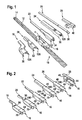
- wiper blade 10 has a wiper strip, which is covered by a spoiler 12 having end caps 14 at its ends.
- the spoiler 12 is connected in a conventional manner with the non-visible wiper strip on a support element in the form of one or more spring rails, which are also not visible.
- a connecting element is mounted in the usual manner, on which an adapter 16 is seated.
- the adapter 16 serves to articulate the wiper blade 10 with six different wiper arms 18, 20, 22, 24, 26 and 28.
- FIG. 2 shows the six wiper arms 18, 20, 22, 24, 26, 28 mounted on the adapter 16.
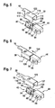
- the adapter 16 comprises a base element 42 and a closure cap 44 for connection to a first wiper arm 18 or a second wiper arm 20, while a cover cap 46 is required for connection to a third wiper arm 22 or fourth wiper arm 24 or fifth wiper arm 26 or sixth wiper arm 28.
- the items of the adapter 16 are in Fig. 3 shown.
- the base member 42 has two side walls 48, which are connected by a bottom 56 and an intermediate bottom 58 with each other and project beyond it in the direction of a vertical axis.
- the end face of the base element 42 facing away from the wiper arms 18, 20, 22, 24, 26, 28 is covered by the closure cap 44.
- This has a U-shaped cross-sectional profile which is open towards the spoiler 12 and is formed by two side walls 82 and a top wall 80 connecting them.
- the closure cap 44 Towards the free end, the closure cap 44 has an end wall 86 with a connection profile 88 for the spoiler 12.
- Lugs 78 are formed on the inner sides of the side walls 82 and extend in the longitudinal direction 124 and in recesses 60 on the outer sides of the side walls 48 of the base member 42 are guided longitudinally displaceable.
- the recesses 60 are bounded below by the bottom 56, which has 60 leading edges 76 at its longitudinal sides in the region of the recesses.
- the latches 78 When the closure cap 44 is closed, the latches 78 extend across transverse mounting gaps 62 in the side walls 48 of the base element 42. The latches 78 in the closed state interrupt the mounting gaps 62 so that receiving spaces 66 are provided towards the bottom 56 at the end of the mounting gaps 62 form.
- 62 recesses 92 are provided on the front sides 90 of the bolt 78 opposite sides of the mounting columns, in which the bolt 78 engage a bit and by locking edges 65 in the region of its front side 90th with latches 64 at the lower edges of the recesses 92 lock.
- spring arms 68 extending in the longitudinal direction are integrally formed on the side walls 48. These extend outwardly offset to the side walls 48 of the base member 42 and have at their free ends laterally outwardly facing keys 70 which in the final position ( Fig. 4 ) engage in recesses 84 in the side walls 82 of the cap 44 from the inside.
- the spring arms 68 paragraphs 69 serve as stops for end faces 127, 129 of the third or fourth connecting element 34, 36 of the third and fourth wiper arm 22, 24.
- the recesses 84 of the closure cap 44 may be designed as openings or depressions.
- the spring arms 68 fix the final mounting position of the cap 44. Furthermore, they have at least one stop 72, whereby the opening movement of the closure cap 44 is limited, so that the latch 78 remain guided in the recesses 60 of the base member 42 even in the open state of the cap 44. As a result, the assembly and disassembly of the wiper arms 18, 20 and the cap 46 is substantially simplified.
- the base member 42 has in the region of its wiper arm end side for mounting the first wiper arm 18 and the second wiper arm 20, a play compensation button 50, which via a spring tongue 52 with the intermediate bottom 58th connected is.
- the lash adjuster button 50 may also serve as an additional securing means of the adapter 16.
- play compensation slots 74 are also provided in the outsides of the side walls 48, into which the second play compensation ribs 118 of the second connection element 32 of the second wiper arm 20 fit.
- clearance compensation surfaces 47, 49 which cooperate with the first play compensation ribs 117 of the first connecting member 30 of the first wiper arm 18.
- the clearance compensation surfaces 47, 49 are inclined slightly inwardly from the bottom 56 of the base member 42 toward the upper edges of the side walls 48 to facilitate assembly of the first connection member 30.
- the play compensation niches 74 and the play compensation surfaces 47, 49 together with the first and second clearance compensation ribs 117, 118 minimize the lateral play of the wiper blade 10 and thus ensure precise lateral guidance of the wiper blade 10.
- the base member 42 has at the open end of the mounting columns 62 in the intermediate bottom 58 an open hub 54, which is dominated by the side walls 48, wherein the protruding parts of Side walls 48 are formed as Klippse to hold a bearing pin 164 of the sixth connecting member 40 in the hub 54.
- the cap 46 has an open to the base member 42, U-shaped cross-sectional profile, which is formed by two side walls 94 and a top wall 96 which connects the side walls 94 together.
- the side walls 94 have at their lower, the base member 42 facing longitudinal edges recesses 102, so that the side walls 94 flush with the leading edges 76 of the intermediate bottom 58.
- the convex end face 98 also adjoins a correspondingly concave end face 99 of the closure cap 44, so that the side walls 82 and the top wall 80 of the closure cap 44 are flush with the side walls 94 and the top wall 96 of the cap 46.
- the cap 46 also has lateral Verrastungseriel 106. These each have an approximately transversely to the longitudinal direction stop 148 and a stop ramp 140, both stop surfaces to the cap 44 have.
- the stop ramp 140 includes the stop 148 at an obtuse angle.
- At the wiper arm end face 100 of the cap 46 there is an opening 108, through which the connecting elements 34, 36, 38 of the wiper arms 22, 24, 26 can be mounted. In the region of the opening 108, a detent 110 is attached to the cap 46, which is required for mounting the fifth wiper arm 26.
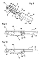
- Fig. 5 and Fig. 6 show the assembly of the first wiper arm 18 to an adapter 16 according to the invention.
- the closure cap 44 is pushed in the longitudinal direction 124 to the stop 72, so that the mounting gaps 62 are free.
- the first connecting element 30 of the first wiper arm 18 can be pushed over the side walls 48 of the base element 42 in the direction of a vertical axis, the securing cams 120 engaging in the mounting gaps 62 and lying in the end positions in the receiving spaces 66 at the end of the mounting gaps 62.
- first play compensation ribs 117 of the side walls 114 of the first connecting element 30 are supported on the bottom 56 and on the leading edge 76, respectively. At the same time they rest without play on the first clearance compensation surfaces 47 and thus provide good lateral guidance.
- the side walls 114 are connected to one another by a cover wall 116.
- the closure cap 44 is displaced in the longitudinal direction 124 toward the first wiper arm 18 until the button 70 on the spring arms 68 from the inside into the recesses 84 formed as openings of the side walls 82 of the closure cap 44 engage.
- the end position is in Fig. 2 shown.
- the latches 78 interrupt the mounting gaps 62 so that the securing cams 120 are caught in the receiving spaces 66.
- the lash adjuster button 50 engages in a corresponding opening 122 of the first connecting element 30, whereby the connecting element 30 is held largely free of play via its end edges 126, the cap 44 and the spring arms 68 with the keys 70.
- the game balance button 50 can also serve as a backup. For this purpose, it has on the spring arms 68 side facing a locking edge 65th
- the second wiper arm 20 extends above the wiper blade 10 (FIG. Fig. 2 . Fig. 7 ).
- the second connection element 32 of the second wiper arm 20 has a similar construction to the first connection element 30 of the first wiper arm 18 and is mounted in the same way, wherein the safety cams 120 are likewise introduced into the accommodation spaces 66.
- the second connection element 32 of the second wiper arm 20 has second clearance compensation ribs 118 on the free longitudinal sides of the side walls 114, which fit into the play compensation slots 74 on the outsides of the side walls 48 and minimize lateral play of the wiper blade 10.
- the convex end faces 127 of the second connecting element 32 lie flush against the concave end faces 99 of the closure cap 44.
- the third wiper arm 22 has a molded, in cross-section U-shaped third connecting element 34 which has two side walls 132, which are interconnected by a top wall 134. On the front side of the top wall 134, a tongue 128 with a hole 130 is formed. Longitudinally offset towards the third wiper arm 22, projections 136 are integrally formed on the free longitudinal edges of the side walls 132, whose wiper arm-side boundary forms an undercut 138.
- the adapter 16 is aligned approximately parallel to the wiper blade 10.
- the third connecting element 34 is pushed through the wiper arm-side opening 108 in the cap 46, wherein the tongue 128 the locking cam 154 of Cover 46 and the lash adjuster button 50 of the base member 42 pushes down.
- the lateral Verrastungseriel 106 are resiliently pressed by the side walls 132 inwardly until the front end 127 of the third connecting element 34 abuts the shoulders 69 of the spring arms 68 and the Verrastungseriel 106 laterally engage in the undercuts 138 of the third connecting element 34.
- the abutment slopes 140 of the Verrastungsinatel 106 abut the opposite edges of the undercuts 138 of the third connecting element 34, so that the third connecting element 34 is held in the longitudinal direction 124 between the paragraphs 69 on the one hand and the stop ramps 140 on the other.
- the inner sides of the side walls 132 of the third connecting element 34 rest approximately free of play against the clearance compensation surfaces 47 and 49 of the base element 42.
- the fourth wiper arm 24 also has an integrally formed fourth connecting element 36. This differs from the third connecting element 34 by the shape of the lateral projections 144, the wischarm workede stop edges 146 which extend substantially perpendicular to the longitudinal direction 124 and with the also perpendicular to the longitudinal direction 124th extending stops 148 of the Verrastungseriel 106 cooperate.
- the mounting is the same as in the third wiper arm 22, wherein the end face 129 of the fourth connecting element 36 in the mounted position on the shoulders 69 of the spring rail 68 and the side wall 132 of the fourth connecting element 36 approximately free of play on the play compensation surfaces 47 and 49 of the Abut base element 42.
- the fifth wiper arm 26 has substantially the shape of a wiper rod with a rectangular cross-section. Its fifth connecting element 38 is integrally formed and has a free end with a crank 150. Placed in the longitudinal direction 124 towards the wiper arm 26, there is a latching hole 152 which, in the end position, when the end face 151 of the cranked fifth connecting element 38 abuts against a stop 142 the inside of the end wall of the closure cap 44 abuts, with the locking cam 154 of the cap 46 locked. During assembly, the fifth connecting element 38 is pushed through the opening 108 of the cap 46, wherein the free end with the crank 150 first pushes the locking cam 154 and the play compensation button 50 back.
- the sixth connection element 40 has a substantially U-shaped cross-sectional profile, which is formed by two side walls 156 and a top wall 158, which connects the two side walls 156 together.
- a bearing pin 164 is riveted in the two side walls 156 .
- the rivet head is designated 166.
- the bearing pin 164 is pushed in a pivoted by 90 degrees position of the wiper blade 10 through the bearing opening 168 in the side wall of the cap 46 into the open hub 54 of the base member 42 and held by the clip-shaped mounting gaps 62.
- a bridge 160 is integrally formed on the sixth connecting element 40, which engages over the cap 46 and holds the adapter 16 with an angled end 162 when the wiper blade 10 is pivoted back into its initial position ,
- the adapter 16 is for mounting the first or second Wiper arm 18, 20 by an angle ⁇ , preferably between 4 ° and 8 °, to the free end of the wiper blade 10 is rotated. Due to the different mounting angle ⁇ , sufficient clearance is obtained for mounting the first and second wiper arm 18, 20 and for connecting the third to fifth connecting elements 34, 36, 38 of the third to fifth wiper arms 22, 24, 26 through the end opening 108 in FIG Insert the adapter 16 and press the lash adjuster button 50 down.
Landscapes
- Engineering & Computer Science (AREA)
- Mechanical Engineering (AREA)
- Ink Jet (AREA)
- Sealing Devices (AREA)
- Pivots And Pivotal Connections (AREA)
- Pinball Game Machines (AREA)
- Cleaning Implements For Floors, Carpets, Furniture, Walls, And The Like (AREA)
- Camera Bodies And Camera Details Or Accessories (AREA)
Priority Applications (1)
| Application Number | Priority Date | Filing Date | Title |
|---|---|---|---|
| PL10760297T PL2501591T3 (pl) | 2009-11-17 | 2010-09-21 | Łącznik do łączenia elementu łączącego na końcu ramienia wycieraczki z piórem wycieraczki, zwłaszcza o płaskiej konstrukcji |
Applications Claiming Priority (3)
| Application Number | Priority Date | Filing Date | Title |
|---|---|---|---|
| DE102009046788 | 2009-11-17 | ||
| PCT/EP2010/063918 WO2011060979A1 (de) | 2009-11-17 | 2010-09-21 | Adapter zum verbinden eines verbindungselements am ende eines wischarms mit einem wischblatt insbesondere in flachbalkenbauweise |
| DE102010041152A DE102010041152A1 (de) | 2009-11-17 | 2010-09-21 | Adapter zum Verbinden eines Verbindungselements am Ende eines Wischarms mit einem Wischblatt insbesondere in Flachbalkenbauweise |
Publications (2)
| Publication Number | Publication Date |
|---|---|
| EP2501591A1 EP2501591A1 (de) | 2012-09-26 |
| EP2501591B1 true EP2501591B1 (de) | 2013-08-14 |
Family
ID=43877800
Family Applications (1)
| Application Number | Title | Priority Date | Filing Date |
|---|---|---|---|
| EP10760297.1A Active EP2501591B1 (de) | 2009-11-17 | 2010-09-21 | Adapter zum verbinden eines verbindungselements am ende eines wischarms mit einem wischblatt insbesondere in flachbalkenbauweise |
Country Status (11)
| Country | Link |
|---|---|
| US (1) | US8850653B2 (ja) |
| EP (1) | EP2501591B1 (ja) |
| JP (1) | JP5362118B2 (ja) |
| KR (1) | KR101381152B1 (ja) |
| CN (1) | CN102596659B (ja) |
| BR (1) | BR112012011686B1 (ja) |
| DE (1) | DE102010041152A1 (ja) |
| ES (1) | ES2428821T3 (ja) |
| IN (1) | IN2012DN02066A (ja) |
| PL (1) | PL2501591T3 (ja) |
| WO (1) | WO2011060979A1 (ja) |
Cited By (4)
| Publication number | Priority date | Publication date | Assignee | Title |
|---|---|---|---|---|
| USD895523S1 (en) | 2019-04-16 | 2020-09-08 | Trico Products Corporation | Coupler for windshield wiper |
| USD896156S1 (en) | 2019-04-16 | 2020-09-15 | Trico Products Corporation | Coupler for windshield wiper |
| USD904275S1 (en) | 2019-04-16 | 2020-12-08 | Trico Products Corporation | Adapter for windshield wiper arm |
| US11529931B2 (en) | 2018-02-19 | 2022-12-20 | Trico Products Corporation | Windshield wiper arm adapter, coupler and assembly |
Families Citing this family (47)
| Publication number | Priority date | Publication date | Assignee | Title |
|---|---|---|---|---|
| US20130227809A1 (en) | 2012-02-24 | 2013-09-05 | Pylon Manufacturing Corp. | Wiper blade |
| US9457768B2 (en) | 2011-04-21 | 2016-10-04 | Pylon Manufacturing Corp. | Vortex damping wiper blade |
| US9174609B2 (en) | 2011-04-21 | 2015-11-03 | Pylon Manufacturing Corp. | Wiper blade with cover |
| CN202115476U (zh) * | 2011-06-14 | 2012-01-18 | 杨志铭 | 可防止驱动刷臂松脱的雨刷结合座 |
| DE102011079131A1 (de) * | 2011-07-14 | 2015-08-13 | Robert Bosch Gmbh | Wischblattadaptervorrichtung |
| DE102011079783A1 (de) | 2011-07-26 | 2013-01-31 | Robert Bosch Gmbh | Anschlussvorrichtung zum gelenkigen Verbinden eines Wischblatts mit einem Wischarm und ein Adapter |
| US9174611B2 (en) | 2011-07-28 | 2015-11-03 | Pylon Manufacturing Corp. | Windshield wiper adapter, connector and assembly |
| US9108595B2 (en) | 2011-07-29 | 2015-08-18 | Pylon Manufacturing Corporation | Windshield wiper connector |
| KR101350276B1 (ko) * | 2011-11-09 | 2014-01-13 | 케이씨더블류 주식회사 | 차량용 와이퍼 커넥터 |
| US10723322B2 (en) | 2012-02-24 | 2020-07-28 | Pylon Manufacturing Corp. | Wiper blade with cover |
| US20130219649A1 (en) | 2012-02-24 | 2013-08-29 | Pylon Manufacturing Corp. | Wiper blade |
| DE112013002985A5 (de) | 2012-06-13 | 2015-03-12 | Robert Bosch Gmbh | Wischblattadaptersystem |
| US10829092B2 (en) | 2012-09-24 | 2020-11-10 | Pylon Manufacturing Corp. | Wiper blade with modular mounting base |
| US10166951B2 (en) | 2013-03-15 | 2019-01-01 | Pylon Manufacturing Corp. | Windshield wiper connector |
| US9555775B2 (en) * | 2013-03-15 | 2017-01-31 | Illinois Tool Works Inc. | Connectors and connector kit for attachment of a windshield wiper blade to multiple types of windshield wiper arms |
| US9511748B2 (en) | 2013-03-15 | 2016-12-06 | Illinois Tool Works Inc. | Universal connector for attachment of a windshield wiper blade with multiple types of windshield wiper arms |
| KR101503661B1 (ko) | 2013-05-15 | 2015-03-25 | 케이씨더블류 주식회사 | 차량용 와이퍼 커넥터 |
| US9365190B2 (en) * | 2013-10-01 | 2016-06-14 | Xiamen Meto Auto Parts Industry Co., Ltd. | Connecting device of windshield wiper |
| USD727238S1 (en) | 2013-12-13 | 2015-04-21 | Illinois Tool Works Inc. | Cover used for windshield wiper connectors |
| CN104176010A (zh) * | 2014-02-08 | 2014-12-03 | 临海市圣远汽车配件有限公司 | 一种新型车辆雨刮器 |
| KR101426005B1 (ko) | 2014-03-07 | 2014-08-05 | 에이디엠이십일 주식회사 | 와이퍼 블레이드 |
| US9505380B2 (en) | 2014-03-07 | 2016-11-29 | Pylon Manufacturing Corp. | Windshield wiper connector and assembly |
| KR101426001B1 (ko) | 2014-03-07 | 2014-08-05 | 에이디엠이십일 주식회사 | 와이퍼 블레이드 |
| WO2016000785A1 (en) * | 2014-07-03 | 2016-01-07 | Federal-Mogul S.A. | Windscreen wiper device |
| MX2016014350A (es) * | 2014-07-16 | 2017-01-27 | Federal Mogul Sa | Dispositivo limpiaparabrisas. |
| USD787308S1 (en) | 2014-10-03 | 2017-05-23 | Pylon Manufacturing Corp. | Wiper blade package |
| USD777079S1 (en) | 2014-10-03 | 2017-01-24 | Pylon Manufacturing Corp. | Wiper blade frame |
| FR3037903B1 (fr) * | 2015-06-26 | 2017-07-14 | Valeo Systemes Dessuyage | Adaptateur pour un essuie-glace de vehicule automobile et ensemble comportant un tel adaptateur |
| DE102015213441A1 (de) * | 2015-07-17 | 2017-01-19 | Robert Bosch Gmbh | Wischblattvorrichtung |
| JP6055519B1 (ja) * | 2015-07-17 | 2016-12-27 | マルエヌ株式会社 | ワイパーブレード |
| US10363905B2 (en) | 2015-10-26 | 2019-07-30 | Pylon Manufacturing Corp. | Wiper blade |
| FR3043041B1 (fr) * | 2015-11-04 | 2017-12-08 | Valeo Systemes Dessuyage | Adaptateur pour un essuie-glace de vehicule automobile |
| EP3398822A4 (en) * | 2015-12-28 | 2019-08-07 | Gos Co. Ltd. | WIPER BLADE ADAPTER ASSEMBLY |
| CN109311452A (zh) | 2016-05-19 | 2019-02-05 | 电缆塔制造有限公司 | 挡风玻璃雨刮器连接器 |
| US10717414B2 (en) | 2016-05-19 | 2020-07-21 | Pylon Manufacturing Corporation | Windshield wiper blade |
| US11040705B2 (en) | 2016-05-19 | 2021-06-22 | Pylon Manufacturing Corp. | Windshield wiper connector |
| WO2017201470A1 (en) | 2016-05-19 | 2017-11-23 | Pylon Manufacturing Corp. | Windshield wiper connector |
| AU2017268019A1 (en) | 2016-05-19 | 2018-11-22 | Pylon Manufacturing Corp. | Windshield wiper connector |
| CN106740701B (zh) * | 2016-09-23 | 2023-12-19 | 厦门富可汽车配件有限公司 | 一种有骨雨刷外壳连接结构 |
| FR3069509B1 (fr) | 2017-07-31 | 2020-09-04 | Valeo Systemes Dessuyage | Adaptateur perfectionne pour un essuie-glace de vehicule automobile, et ensemble comportant un tel adaptateur |
| USD900700S1 (en) * | 2018-12-05 | 2020-11-03 | Robert Bosch Gmbh | Wiper arm |
| FR3091232B1 (fr) * | 2018-12-28 | 2022-08-05 | Valeo Systemes Dessuyage | Ensemble de fixation pour système d’essuyage de véhicule automobile |
| CN113748056A (zh) * | 2019-04-30 | 2021-12-03 | 特瑞科比利时股份公司 | 平片型风挡刮水器装置 |
| FR3107682A1 (fr) * | 2020-02-28 | 2021-09-03 | Valeo Systèmes D’Essuyage | Dispositif de connexion d’un balai d’essuyage à un bras d’essuie-glace |
| FR3112738B1 (fr) * | 2020-07-22 | 2022-07-15 | Valeo Systemes Dessuyage | Dispositif de connexion d’un balai d’essuyage à un bras d’essuie-glace |
| CN113479168B (zh) * | 2020-11-09 | 2023-02-28 | 厦门富可汽车配件有限公司 | 一种适配器及雨刷 |
| EP4116156A1 (en) | 2021-07-06 | 2023-01-11 | Trico Belgium S.A. | A windscreen wiper device of the flat blade type |
Family Cites Families (13)
| Publication number | Priority date | Publication date | Assignee | Title |
|---|---|---|---|---|
| FR2879986B1 (fr) | 2004-12-23 | 2008-07-11 | Valeo Systemes Dessuyage | Balai d'essuie-glace plat universel et connecteur amovible associe |
| US7299520B2 (en) * | 2006-03-24 | 2007-11-27 | Shih-Hsien Huang | Connecting device for a windshield wiper having no support frame and hook type windshield wiper arm |
| TW200736100A (en) * | 2006-03-25 | 2007-10-01 | Shih-Hsien Huang | Connecting device for a windshield wiper having no support frame and hook type windshield wiper arm |
| EP1849666B1 (en) * | 2006-04-28 | 2011-02-23 | Federal-Mogul S.A. | A windscreen wiper device |
| DE102007021333A1 (de) * | 2007-05-07 | 2008-11-13 | Robert Bosch Gmbh | Anschlussvorrichtung zum gelenkigen Verbinden eines Wischblatts mit einem Wischarm |
| KR100889959B1 (ko) * | 2007-05-21 | 2009-03-20 | 에이디엠이십일 주식회사 | 와이퍼 블레이드 |
| JP4712025B2 (ja) | 2007-05-21 | 2011-06-29 | エイディエム21 カンパニー リミテッド | ワイパーブレード |
| KR100889958B1 (ko) * | 2007-05-30 | 2009-03-20 | 에이디엠이십일 주식회사 | 와이퍼 블레이드 |
| DE102007058091A1 (de) * | 2007-12-03 | 2009-06-04 | Robert Bosch Gmbh | Wischblatt |
| KR100891195B1 (ko) * | 2008-04-30 | 2009-04-02 | 주식회사 캐프 | 차량용 범용 와이퍼 장치 |
| KR100903374B1 (ko) | 2008-07-11 | 2009-06-23 | 에이디엠이십일 주식회사 | 플랫 와이퍼 블레이드와 와이퍼 아암의 결합장치 |
| DE202008011314U1 (de) * | 2008-08-25 | 2008-10-23 | FU GANG CO., LTD., Wujie | Befestigung für ein Wischblatt |
| DE102008049269B4 (de) * | 2008-09-26 | 2020-08-27 | Valeo Systèmes d'Essuyage | Wischarm/Wischblatt-Verbindung sowie Wischblatt |
-
2010
- 2010-09-21 ES ES10760297T patent/ES2428821T3/es active Active
- 2010-09-21 KR KR1020127011544A patent/KR101381152B1/ko active IP Right Grant
- 2010-09-21 BR BR112012011686A patent/BR112012011686B1/pt not_active IP Right Cessation
- 2010-09-21 JP JP2012532529A patent/JP5362118B2/ja active Active
- 2010-09-21 WO PCT/EP2010/063918 patent/WO2011060979A1/de active Application Filing
- 2010-09-21 CN CN201080051865.0A patent/CN102596659B/zh active Active
- 2010-09-21 EP EP10760297.1A patent/EP2501591B1/de active Active
- 2010-09-21 PL PL10760297T patent/PL2501591T3/pl unknown
- 2010-09-21 US US13/510,520 patent/US8850653B2/en active Active
- 2010-09-21 DE DE102010041152A patent/DE102010041152A1/de not_active Withdrawn
-
2012
- 2012-03-07 IN IN2066DEN2012 patent/IN2012DN02066A/en unknown
Cited By (4)
| Publication number | Priority date | Publication date | Assignee | Title |
|---|---|---|---|---|
| US11529931B2 (en) | 2018-02-19 | 2022-12-20 | Trico Products Corporation | Windshield wiper arm adapter, coupler and assembly |
| USD895523S1 (en) | 2019-04-16 | 2020-09-08 | Trico Products Corporation | Coupler for windshield wiper |
| USD896156S1 (en) | 2019-04-16 | 2020-09-15 | Trico Products Corporation | Coupler for windshield wiper |
| USD904275S1 (en) | 2019-04-16 | 2020-12-08 | Trico Products Corporation | Adapter for windshield wiper arm |
Also Published As
| Publication number | Publication date |
|---|---|
| US8850653B2 (en) | 2014-10-07 |
| JP2013507285A (ja) | 2013-03-04 |
| BR112012011686B1 (pt) | 2020-02-04 |
| EP2501591A1 (de) | 2012-09-26 |
| DE102010041152A1 (de) | 2011-05-19 |
| JP5362118B2 (ja) | 2013-12-11 |
| BR112012011686A2 (pt) | 2016-03-01 |
| CN102596659B (zh) | 2015-05-20 |
| CN102596659A (zh) | 2012-07-18 |
| WO2011060979A1 (de) | 2011-05-26 |
| PL2501591T3 (pl) | 2014-01-31 |
| IN2012DN02066A (ja) | 2015-08-21 |
| KR20120062020A (ko) | 2012-06-13 |
| US20120279008A1 (en) | 2012-11-08 |
| ES2428821T3 (es) | 2013-11-11 |
| KR101381152B1 (ko) | 2014-04-04 |
Similar Documents
| Publication | Publication Date | Title |
|---|---|---|
| EP2501591B1 (de) | Adapter zum verbinden eines verbindungselements am ende eines wischarms mit einem wischblatt insbesondere in flachbalkenbauweise | |
| EP2424755B1 (de) | Anschlussvorrichtung zum gelenkigen verbinden eines mit einem wischarm fest verbundenen verbindungselements | |
| EP2588352B1 (de) | Anschlussvorrichtung zum gelenkigen verbinden eines wischarms mit einem wischblatt | |
| EP2550186B1 (de) | Adapter zum gelenkigen verbinden eines verbindungselements am ende eines wischarms mit einem anschlusselement eines wischblatts | |
| EP2190703B1 (de) | Wischblatt | |
| EP2552755B1 (de) | Anschlussvorrichtung zum gelenkigen verbinden eines wischarms mit einem wischblatt | |
| EP2259954B1 (de) | Wischblatt | |
| EP2113432B2 (de) | Scheibenwischer, insbesondere für Kraftfahrzeuge | |
| EP2127969B1 (de) | Wischblatt | |
| EP2326538B1 (de) | Anschlussvorrichtung zum gelenkigen verbinden eines wischblatts mit einem wischarm | |
| EP2678195A1 (de) | Wischblatt und endkappe | |
| WO2009071372A1 (de) | Wischblatt | |
| WO2010028918A1 (de) | Vorrichtung zum gelenkigen verbinden eines wischblatts mit einem wischarm eines scheibenwischers | |
| DE102004051466A1 (de) | Wischblatt | |
| DE102011079783A1 (de) | Anschlussvorrichtung zum gelenkigen Verbinden eines Wischblatts mit einem Wischarm und ein Adapter | |
| EP2179901A2 (de) | Anschlussvorrichtung zum gelenkigen Verbinden eines Wischblatts in Flachbalkenbauweise mit einem Wischarm | |
| DE112007000255T5 (de) | Verbindungselement an einem Wischerblatt | |
| EP2303650B1 (de) | Baureihe eines wischblatts | |
| WO2008049686A1 (de) | Wischblatt | |
| DE102015116856B4 (de) | Gurtschloss mit Rippenelement |
Legal Events
| Date | Code | Title | Description |
|---|---|---|---|
| PUAI | Public reference made under article 153(3) epc to a published international application that has entered the european phase |
Free format text: ORIGINAL CODE: 0009012 |
|
| 17P | Request for examination filed |
Effective date: 20120618 |
|
| AK | Designated contracting states |
Kind code of ref document: A1 Designated state(s): AL AT BE BG CH CY CZ DE DK EE ES FI FR GB GR HR HU IE IS IT LI LT LU LV MC MK MT NL NO PL PT RO SE SI SK SM TR |
|
| DAX | Request for extension of the european patent (deleted) | ||
| GRAP | Despatch of communication of intention to grant a patent |
Free format text: ORIGINAL CODE: EPIDOSNIGR1 |
|
| INTG | Intention to grant announced |
Effective date: 20130429 |
|
| GRAS | Grant fee paid |
Free format text: ORIGINAL CODE: EPIDOSNIGR3 |
|
| GRAA | (expected) grant |
Free format text: ORIGINAL CODE: 0009210 |
|
| AK | Designated contracting states |
Kind code of ref document: B1 Designated state(s): AL AT BE BG CH CY CZ DE DK EE ES FI FR GB GR HR HU IE IS IT LI LT LU LV MC MK MT NL NO PL PT RO SE SI SK SM TR |
|
| REG | Reference to a national code |
Ref country code: GB Ref legal event code: FG4D Free format text: NOT ENGLISH |
|
| REG | Reference to a national code |
Ref country code: AT Ref legal event code: REF Ref document number: 626612 Country of ref document: AT Kind code of ref document: T Effective date: 20130815 Ref country code: CH Ref legal event code: EP |
|
| REG | Reference to a national code |
Ref country code: IE Ref legal event code: FG4D Free format text: LANGUAGE OF EP DOCUMENT: GERMAN |
|
| REG | Reference to a national code |
Ref country code: DE Ref legal event code: R096 Ref document number: 502010004397 Country of ref document: DE Effective date: 20131010 |
|
| REG | Reference to a national code |
Ref country code: ES Ref legal event code: FG2A Ref document number: 2428821 Country of ref document: ES Kind code of ref document: T3 Effective date: 20131111 |
|
| REG | Reference to a national code |
Ref country code: SE Ref legal event code: TRGR |
|
| REG | Reference to a national code |
Ref country code: NL Ref legal event code: T3 |
|
| REG | Reference to a national code |
Ref country code: LT Ref legal event code: MG4D |
|
| PG25 | Lapsed in a contracting state [announced via postgrant information from national office to epo] |
Ref country code: LT Free format text: LAPSE BECAUSE OF FAILURE TO SUBMIT A TRANSLATION OF THE DESCRIPTION OR TO PAY THE FEE WITHIN THE PRESCRIBED TIME-LIMIT Effective date: 20130814 Ref country code: IS Free format text: LAPSE BECAUSE OF FAILURE TO SUBMIT A TRANSLATION OF THE DESCRIPTION OR TO PAY THE FEE WITHIN THE PRESCRIBED TIME-LIMIT Effective date: 20131214 Ref country code: PT Free format text: LAPSE BECAUSE OF FAILURE TO SUBMIT A TRANSLATION OF THE DESCRIPTION OR TO PAY THE FEE WITHIN THE PRESCRIBED TIME-LIMIT Effective date: 20131216 Ref country code: CY Free format text: LAPSE BECAUSE OF FAILURE TO SUBMIT A TRANSLATION OF THE DESCRIPTION OR TO PAY THE FEE WITHIN THE PRESCRIBED TIME-LIMIT Effective date: 20130911 Ref country code: HR Free format text: LAPSE BECAUSE OF FAILURE TO SUBMIT A TRANSLATION OF THE DESCRIPTION OR TO PAY THE FEE WITHIN THE PRESCRIBED TIME-LIMIT Effective date: 20130814 Ref country code: NO Free format text: LAPSE BECAUSE OF FAILURE TO SUBMIT A TRANSLATION OF THE DESCRIPTION OR TO PAY THE FEE WITHIN THE PRESCRIBED TIME-LIMIT Effective date: 20131114 |
|
| REG | Reference to a national code |
Ref country code: PL Ref legal event code: T3 |
|
| PG25 | Lapsed in a contracting state [announced via postgrant information from national office to epo] |
Ref country code: LV Free format text: LAPSE BECAUSE OF FAILURE TO SUBMIT A TRANSLATION OF THE DESCRIPTION OR TO PAY THE FEE WITHIN THE PRESCRIBED TIME-LIMIT Effective date: 20130814 Ref country code: SI Free format text: LAPSE BECAUSE OF FAILURE TO SUBMIT A TRANSLATION OF THE DESCRIPTION OR TO PAY THE FEE WITHIN THE PRESCRIBED TIME-LIMIT Effective date: 20130814 Ref country code: GR Free format text: LAPSE BECAUSE OF FAILURE TO SUBMIT A TRANSLATION OF THE DESCRIPTION OR TO PAY THE FEE WITHIN THE PRESCRIBED TIME-LIMIT Effective date: 20131115 Ref country code: FI Free format text: LAPSE BECAUSE OF FAILURE TO SUBMIT A TRANSLATION OF THE DESCRIPTION OR TO PAY THE FEE WITHIN THE PRESCRIBED TIME-LIMIT Effective date: 20130814 |
|
| PG25 | Lapsed in a contracting state [announced via postgrant information from national office to epo] |
Ref country code: CY Free format text: LAPSE BECAUSE OF FAILURE TO SUBMIT A TRANSLATION OF THE DESCRIPTION OR TO PAY THE FEE WITHIN THE PRESCRIBED TIME-LIMIT Effective date: 20130814 |
|
| PG25 | Lapsed in a contracting state [announced via postgrant information from national office to epo] |
Ref country code: DK Free format text: LAPSE BECAUSE OF FAILURE TO SUBMIT A TRANSLATION OF THE DESCRIPTION OR TO PAY THE FEE WITHIN THE PRESCRIBED TIME-LIMIT Effective date: 20130814 Ref country code: RO Free format text: LAPSE BECAUSE OF FAILURE TO SUBMIT A TRANSLATION OF THE DESCRIPTION OR TO PAY THE FEE WITHIN THE PRESCRIBED TIME-LIMIT Effective date: 20130814 Ref country code: SK Free format text: LAPSE BECAUSE OF FAILURE TO SUBMIT A TRANSLATION OF THE DESCRIPTION OR TO PAY THE FEE WITHIN THE PRESCRIBED TIME-LIMIT Effective date: 20130814 Ref country code: CZ Free format text: LAPSE BECAUSE OF FAILURE TO SUBMIT A TRANSLATION OF THE DESCRIPTION OR TO PAY THE FEE WITHIN THE PRESCRIBED TIME-LIMIT Effective date: 20130814 Ref country code: EE Free format text: LAPSE BECAUSE OF FAILURE TO SUBMIT A TRANSLATION OF THE DESCRIPTION OR TO PAY THE FEE WITHIN THE PRESCRIBED TIME-LIMIT Effective date: 20130814 |
|
| PG25 | Lapsed in a contracting state [announced via postgrant information from national office to epo] |
Ref country code: MC Free format text: LAPSE BECAUSE OF FAILURE TO SUBMIT A TRANSLATION OF THE DESCRIPTION OR TO PAY THE FEE WITHIN THE PRESCRIBED TIME-LIMIT Effective date: 20130814 |
|
| PLBE | No opposition filed within time limit |
Free format text: ORIGINAL CODE: 0009261 |
|
| STAA | Information on the status of an ep patent application or granted ep patent |
Free format text: STATUS: NO OPPOSITION FILED WITHIN TIME LIMIT |
|
| REG | Reference to a national code |
Ref country code: IE Ref legal event code: MM4A |
|
| 26N | No opposition filed |
Effective date: 20140515 |
|
| PG25 | Lapsed in a contracting state [announced via postgrant information from national office to epo] |
Ref country code: IE Free format text: LAPSE BECAUSE OF NON-PAYMENT OF DUE FEES Effective date: 20130921 |
|
| REG | Reference to a national code |
Ref country code: DE Ref legal event code: R097 Ref document number: 502010004397 Country of ref document: DE Effective date: 20140515 |
|
| REG | Reference to a national code |
Ref country code: HU Ref legal event code: AG4A Ref document number: E020089 Country of ref document: HU |
|
| REG | Reference to a national code |
Ref country code: CH Ref legal event code: PL |
|
| PG25 | Lapsed in a contracting state [announced via postgrant information from national office to epo] |
Ref country code: SM Free format text: LAPSE BECAUSE OF FAILURE TO SUBMIT A TRANSLATION OF THE DESCRIPTION OR TO PAY THE FEE WITHIN THE PRESCRIBED TIME-LIMIT Effective date: 20130814 |
|
| PG25 | Lapsed in a contracting state [announced via postgrant information from national office to epo] |
Ref country code: TR Free format text: LAPSE BECAUSE OF FAILURE TO SUBMIT A TRANSLATION OF THE DESCRIPTION OR TO PAY THE FEE WITHIN THE PRESCRIBED TIME-LIMIT Effective date: 20130814 Ref country code: MT Free format text: LAPSE BECAUSE OF FAILURE TO SUBMIT A TRANSLATION OF THE DESCRIPTION OR TO PAY THE FEE WITHIN THE PRESCRIBED TIME-LIMIT Effective date: 20130814 |
|
| PG25 | Lapsed in a contracting state [announced via postgrant information from national office to epo] |
Ref country code: LI Free format text: LAPSE BECAUSE OF NON-PAYMENT OF DUE FEES Effective date: 20140930 Ref country code: BG Free format text: LAPSE BECAUSE OF FAILURE TO SUBMIT A TRANSLATION OF THE DESCRIPTION OR TO PAY THE FEE WITHIN THE PRESCRIBED TIME-LIMIT Effective date: 20130814 Ref country code: LU Free format text: LAPSE BECAUSE OF NON-PAYMENT OF DUE FEES Effective date: 20130921 Ref country code: CH Free format text: LAPSE BECAUSE OF NON-PAYMENT OF DUE FEES Effective date: 20140930 Ref country code: MK Free format text: LAPSE BECAUSE OF FAILURE TO SUBMIT A TRANSLATION OF THE DESCRIPTION OR TO PAY THE FEE WITHIN THE PRESCRIBED TIME-LIMIT Effective date: 20130814 |
|
| REG | Reference to a national code |
Ref country code: FR Ref legal event code: PLFP Year of fee payment: 7 |
|
| REG | Reference to a national code |
Ref country code: AT Ref legal event code: MM01 Ref document number: 626612 Country of ref document: AT Kind code of ref document: T Effective date: 20150921 |
|
| PG25 | Lapsed in a contracting state [announced via postgrant information from national office to epo] |
Ref country code: AT Free format text: LAPSE BECAUSE OF NON-PAYMENT OF DUE FEES Effective date: 20150921 |
|
| REG | Reference to a national code |
Ref country code: FR Ref legal event code: PLFP Year of fee payment: 8 |
|
| REG | Reference to a national code |
Ref country code: FR Ref legal event code: PLFP Year of fee payment: 9 |
|
| PG25 | Lapsed in a contracting state [announced via postgrant information from national office to epo] |
Ref country code: AL Free format text: LAPSE BECAUSE OF FAILURE TO SUBMIT A TRANSLATION OF THE DESCRIPTION OR TO PAY THE FEE WITHIN THE PRESCRIBED TIME-LIMIT Effective date: 20130814 |
|
| PGFP | Annual fee paid to national office [announced via postgrant information from national office to epo] |
Ref country code: IT Payment date: 20190920 Year of fee payment: 10 Ref country code: SE Payment date: 20190924 Year of fee payment: 10 Ref country code: NL Payment date: 20190923 Year of fee payment: 10 |
|
| PGFP | Annual fee paid to national office [announced via postgrant information from national office to epo] |
Ref country code: HU Payment date: 20190912 Year of fee payment: 10 Ref country code: PL Payment date: 20190912 Year of fee payment: 10 |
|
| PGFP | Annual fee paid to national office [announced via postgrant information from national office to epo] |
Ref country code: GB Payment date: 20190924 Year of fee payment: 10 |
|
| PGFP | Annual fee paid to national office [announced via postgrant information from national office to epo] |
Ref country code: ES Payment date: 20191023 Year of fee payment: 10 |
|
| REG | Reference to a national code |
Ref country code: NL Ref legal event code: MM Effective date: 20201001 |
|
| GBPC | Gb: european patent ceased through non-payment of renewal fee |
Effective date: 20200921 |
|
| PG25 | Lapsed in a contracting state [announced via postgrant information from national office to epo] |
Ref country code: NL Free format text: LAPSE BECAUSE OF NON-PAYMENT OF DUE FEES Effective date: 20201001 |
|
| PG25 | Lapsed in a contracting state [announced via postgrant information from national office to epo] |
Ref country code: SE Free format text: LAPSE BECAUSE OF NON-PAYMENT OF DUE FEES Effective date: 20200922 Ref country code: GB Free format text: LAPSE BECAUSE OF NON-PAYMENT OF DUE FEES Effective date: 20200921 Ref country code: HU Free format text: LAPSE BECAUSE OF NON-PAYMENT OF DUE FEES Effective date: 20200922 |
|
| REG | Reference to a national code |
Ref country code: SE Ref legal event code: EUG |
|
| REG | Reference to a national code |
Ref country code: ES Ref legal event code: FD2A Effective date: 20220118 |
|
| PG25 | Lapsed in a contracting state [announced via postgrant information from national office to epo] |
Ref country code: IT Free format text: LAPSE BECAUSE OF NON-PAYMENT OF DUE FEES Effective date: 20200921 |
|
| PG25 | Lapsed in a contracting state [announced via postgrant information from national office to epo] |
Ref country code: ES Free format text: LAPSE BECAUSE OF NON-PAYMENT OF DUE FEES Effective date: 20200922 |
|
| PG25 | Lapsed in a contracting state [announced via postgrant information from national office to epo] |
Ref country code: PL Free format text: LAPSE BECAUSE OF NON-PAYMENT OF DUE FEES Effective date: 20200921 |
|
| PGFP | Annual fee paid to national office [announced via postgrant information from national office to epo] |
Ref country code: FR Payment date: 20230918 Year of fee payment: 14 Ref country code: BE Payment date: 20230918 Year of fee payment: 14 |
|
| PGFP | Annual fee paid to national office [announced via postgrant information from national office to epo] |
Ref country code: DE Payment date: 20231124 Year of fee payment: 14 |