EP2500644B1 - Verbrennungsplatte - Google Patents
Verbrennungsplatte Download PDFInfo
- Publication number
- EP2500644B1 EP2500644B1 EP10828056.1A EP10828056A EP2500644B1 EP 2500644 B1 EP2500644 B1 EP 2500644B1 EP 10828056 A EP10828056 A EP 10828056A EP 2500644 B1 EP2500644 B1 EP 2500644B1
- Authority
- EP
- European Patent Office
- Prior art keywords
- flame
- combustion
- flame holes
- equilateral hexagon
- hole
- Prior art date
- Legal status (The legal status is an assumption and is not a legal conclusion. Google has not performed a legal analysis and makes no representation as to the accuracy of the status listed.)
- Not-in-force
Links
Images





Classifications
-
- F—MECHANICAL ENGINEERING; LIGHTING; HEATING; WEAPONS; BLASTING
- F23—COMBUSTION APPARATUS; COMBUSTION PROCESSES
- F23D—BURNERS
- F23D14/00—Burners for combustion of a gas, e.g. of a gas stored under pressure as a liquid
- F23D14/46—Details
- F23D14/48—Nozzles
- F23D14/58—Nozzles characterised by the shape or arrangement of the outlet or outlets from the nozzle, e.g. of annular configuration
-
- F—MECHANICAL ENGINEERING; LIGHTING; HEATING; WEAPONS; BLASTING
- F23—COMBUSTION APPARATUS; COMBUSTION PROCESSES
- F23D—BURNERS
- F23D14/00—Burners for combustion of a gas, e.g. of a gas stored under pressure as a liquid
- F23D14/26—Burners for combustion of a gas, e.g. of a gas stored under pressure as a liquid with provision for a retention flame
-
- F—MECHANICAL ENGINEERING; LIGHTING; HEATING; WEAPONS; BLASTING
- F23—COMBUSTION APPARATUS; COMBUSTION PROCESSES
- F23D—BURNERS
- F23D14/00—Burners for combustion of a gas, e.g. of a gas stored under pressure as a liquid
- F23D14/34—Burners specially adapted for use with means for pressurising the gaseous fuel or the combustion air
-
- F—MECHANICAL ENGINEERING; LIGHTING; HEATING; WEAPONS; BLASTING
- F23—COMBUSTION APPARATUS; COMBUSTION PROCESSES
- F23D—BURNERS
- F23D14/00—Burners for combustion of a gas, e.g. of a gas stored under pressure as a liquid
- F23D14/46—Details
- F23D14/72—Safety devices, e.g. operative in case of failure of gas supply
- F23D14/74—Preventing flame lift-off
-
- F—MECHANICAL ENGINEERING; LIGHTING; HEATING; WEAPONS; BLASTING
- F23—COMBUSTION APPARATUS; COMBUSTION PROCESSES
- F23D—BURNERS
- F23D2203/00—Gaseous fuel burners
- F23D2203/10—Flame diffusing means
- F23D2203/102—Flame diffusing means using perforated plates
- F23D2203/1023—Flame diffusing means using perforated plates with specific free passage areas
-
- F—MECHANICAL ENGINEERING; LIGHTING; HEATING; WEAPONS; BLASTING
- F23—COMBUSTION APPARATUS; COMBUSTION PROCESSES
- F23D—BURNERS
- F23D2210/00—Noise abatement
Definitions
- the present invention relates to a combustion plate to be used in a totally aerated combustion burner (or a fully primary aerated burner) which is equipped in a heat source apparatus mainly for supplying hot water or for heating space, and relates to the combustion plate which is made by forming, in a plate main body of ceramic make, a multiplicity of flame holes for ejecting premixed gas.
- Patent Document 1 a combustion plate in which flame holes are formed over the entire surface of the combustion plate such that three kinds of large, middle, and small flame holes are positioned so that: various kinds of flame holes are distributed in lattice shape; and that the large hole is positioned in the center of the four adjoining small flame holes and is also positioned in the center of the adjoining four middle flame holes; that each of the small flame holes is formed so as to be positioned in the middle of the adjoining two middle flame holes; and that on the surface of a plate main body there is formed a bottomed hole which is coaxial with each of the large flame holes and partly includes each of the small flame holes that are present in the circumference of the large flame hole.
- the opening ratio (the ratio of total area of the entire flame holes to the total area of the combustion region of the plate main body) becomes comparatively small.
- the opening ratio was about 26 %. Therefore, there was a disadvantage in that a passage resistance through the combustion plate becomes large, with a resultant increased load on the fan to supply primary air to the burner increase, whereby the fan noises become large.
- Patent Document 1 TOKKOHEI 7-59966 (Examined Patent Publication No. 1995-59966 )
- US 3 825 403 A relates to a burner plate for infrared radiators having depressions on the radiating side and having combustion passages for conveying the fuel-air mixture from the mixing side of the plate to the radiating side, the combustion passages being arranged parallel to each other while at least one of the combustion passages is coaxially arranged at the bottom of a depression whereas the other combustion passages are distributed over the sides of the depressions and over the surfaces between the depressions.
- US 4 569 657 A relates to a plate with a alveolar radiating face for radiant burners.
- this invention has a problem of providing a combustion plate which is capable of solving the combustion resonant sounds and instability at the time of high-load combustion and which is also capable of securing a larger opening degree of the flame holes.
- the flame holes of the same diameter in such a positional relationship that the adjoining three flame holes form an equilateral triangle, the flame holes can be disposed in as much densest manner as possible within a limit in which the combustion plate can be manufactured.
- the opening ratio of the flame holes can be largely increased as compared with the conventional examples, so that the resistance to pass through the combustion plate can be reduced.
- the load on the fan to supply the primary air to the burner can thus be decreased and the fan noise can be reduced.
- the premixed gas to be ejected from the six flame holes that are in the positional relationship to form an equilateral hexagon of each of the unit flame holes has a velocity component toward the center of the bottomed hole.
- the shape of the aggregated flames to be formed by the combustion of the premixed gas ejected from the bottomed hole of the unit flame hole group becomes a mountain shape without a steep rise.
- each of the aggregated flames to be formed by the combustion of the premixed gas ejected from the bottomed holes of each of the unit flame holes lies next to one another, the aggregated flames get resonant with one another to thereby generate large combustion resonant sounds.
- the aggregated flames since there exist large equilateral hexagonal flame holes among each of the unit flame hole groups, there will be formed flames that are separated from the aggregated flames as a result of combustion of the premixed gas ejected from these flame holes. Resonance among the aggregated flames will thus be restricted, whereby the combustion resonant sounds will be reduced.
- the premixed gas to be ejected from the six flame holes in such a positional relationship as to form equilateral hexagon of each of the unit flame holes advantageously becomes easy to have the velocity component in the central direction of the bottomed hole.
- the depth of the lowermost portion of the peripheral surface of the bottomed hole becomes smaller than 1 mm, the aggregated flames are less likely to be formed, whereby the combustion becomes unstable.
- the depth of the lowermost portion of the peripheral surface of the bottomed hole exceeds 3 mm, the premixed gas to be ejected from the six flame holes that form equilateral hexagon of the unit flame hole group becomes a parallel flow when it comes out of the bottomed hole, whereby an effect of maintaining a stable flame becomes hardly obtainable. Therefore, it is preferable to keep the depth of the lowermost portion in the periphery of the bottomed hole above 1 mm and below 3 mm.
- a predetermined diagonal direction of, or an opposing direction of predetermined opposite sides of, the equilateral hexagon to be constituted by six flame holes in the unit flame hole group is defined as a row direction, and closure (or closing) is made of at least such partial flame holes out of the twelve flame holes as are positioned on the large equilateral hexagon that encloses each of the unit flame hole groups belonging to a selected row, the selected row being selected at a predetermined distance in a direction perpendicular to the row direction out of the unit flame hole groups arrayed in the row direction.
- the predetermined distance is set such that, where the row direction is the diagonal direction, at least three non-selected rows are present between each of the selected rows and that, where the row direction is the opposing direction of the opposite sides, at least two non-selected rows are present between each of the selected rows. Then, the generation of resonance among the aggregated flames is limited to a partial region of the combustion plate, whereby the combustion resonant sounds can be reduced.
- the flame holes to be subjected to closure are the flame holes positioned at each of the corner portions of the large equilateral hexagon. According to this arrangement, there can be obtained an effect similar in degree to the effect in which all of the flame holes that are positioned on the large equilateral hexagons are closed. Further, as compared with the example in which all of the flame holes positioned on the large equilateral hexagons are closed, the opening degree of the flame holes can advantageously be made larger.
- FIG. 1 shows a heat source apparatus for the purpose of supplying hot water or of heating space, the apparatus being provided with a totally aerated combustion burner 2 using a combustion plate 1.
- the burner 2 has a fan 3 connected to the burner 2 via an air duct 3a. Further, the air duct 3a is provided with a gas nozzle 4 which injects a fuel gas into the air duct 3a. Premixed gas of primary air to be supplied by the fan 3 and the fuel gas to be injected from the gas nozzle 4 are ejected via the combustion plate 1 and burnt so as to heat, by the combustion gas, a heat exchanger 5 for supplying hot water or for heating space.
- the fan 3 is controlled such that the amount of the primary air becomes larger than a stoichiometric amount of air required for complete combustion of the fuel gas.
- the premixed gas having an excess air ratio (primary air amount / stoichiometric air amount) of larger than 1 is ejected via the combustion plate 1 to thereby perform totally aerated combustion.
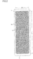
- the combustion plate 1 is made by forming a multiplicity of flame holes 12, which eject premixed gas, in a plate main body 11 which is made of ceramics and is rectangular in shape as seen in plan view.
- flame holes 12 of the same diameter are formed evenly over the entire surface of the combustion region of the plate main body 11 in such a positional relationship that the adjoining three flame holes 12 form an equilateral triangle.
- the thickness of the plate main body 11 is 13 mm.
- the diameter of the flame hole 12 exceeding 1.5 mm is likely to cause back fire (flash back) and that the diameter thereof below 0.8 mm is likely to give rise to difficulties in manufacturing of the combustion plate 1. Therefore, it is desirable to set the diameter of the flame hole12 to 0.8 mm - 1.5 mm.
- the distance between the centers of the flame holes i.e., the pitch
- the flame holes 12 can be arranged in the densest manner within a range that is capable of manufacturing. In this embodiment the diameter of the flame hole 12 is set to be 1.25 mm, and the pitch to be 1.9 mm.
- the opening ratio of the flame holes 12 is 36 %, and this opening ratio is a large increase as compared with that described as an example in the above-mentioned Patent Document 1.
- the resistance to pass through the combustion plate 1 is decreased, the load on the fan 3 is reduced, and the fan noises at the time of high-load combustion can be effectively reduced.
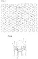
- a flame hole group which is made up of six flame holes 12 disposed in a positional relationship to form an equilateral hexagon 13 and one flame hole 12 in the center of the equilateral hexagon 13 is defined as a unit flame hole group when disposed (or when lying) adjacent to another flame hole group across a large equilateral hexagon 14 which is made up of a flame hole 12 at each of the corner portions and a flame hole 12 in the middle of each of the sides of the equilateral hexagon 14.
- a bottomed hole 15 is formed in the surface of the plate main body 11 in a manner: to be coaxial with the flame hole 12 in the center of each unit flame hole group; to be smaller than the diameter of a circle circumscribing the six flame holes 12 that are in such a positional relationship as to form an equilateral hexagon 13; and to be larger than the diameter of a circle inscribing the six flame holes 12.
- the diameter of the bottomed hole 15 is set to be 4 mm, and an arrangement is made that one-half of the inner side of each of the flame holes 12 in the positional relationship to form an equilateral hexagon 13 lies within the bottomed hole 15.
- the premixed gas to be ejected from each of the flame holes 12 in the positional relationship to form an equilateral hexagon 13 of the unit flame hole group comes to have a velocity component toward the central direction of the bottomed hole 15. Therefore, there can be obtained an effect of reducing the ejecting velocity of the premixed gas in the direction of the normal to the surface of the combustion plate.
- the shape of the aggregated flames F formed by the combustion of the premixed gas that is ejected from the bottomed hole 15 of the unit flame hole group becomes a mountain shape without steep rises. There can thus be obtained a flame stabilizing effect to restrict the flame liftoff at the time of high-load combustion. Therefore, despite the fact that the flame holes 12 are all made in the same diameter, there can be secured the combustion stability at the time of high-load combustion.
- the bottom surface of the bottomed hole 15 is formed into a tapered surface 15a which becomes gradually deeper toward the center. According to this arrangement, the velocity component, toward the central direction, of the bottomed hole 15 can be more effectively added to the premixed gas that is ejected from each of the flame holes 12 in such a positional relationship as will form equilateral hexagon 13 of the unit flame hole groups.
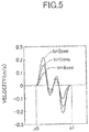
- the velocity on the ordinate is represented on condition that the components toward the central direction to the right in FIG. 4 is plus, and the component toward the central direction to the left in FIG. 4 is minus.
- the values in the above-mentioned flow rate are equivalent to the values when a premixed gas, the fuel gas of which is methane and air excess ratio is 1.6, is supplied at an input of 12 kW.
- the bottom surface 15a of the bottomed hole 15 is formed into a tapered surface. It is also possible to form the bottomed hole 15 so as to become gradually reduced in diameter toward the bottom surface as shown in FIG. 6(a) , or the bottomed hole 15 is formed so as to become reduced stepwise in diameter toward the bottom surface as shown in FIG. 6(b) , or the bottomed hole 15 is formed into a rounded shape so as to become gradually reduced in diameter toward the bottom surface as shown in FIG. 6(c) , such that the velocity component toward the central direction of the bottomed hole 15 can be easily given to the premixed gas to be ejected from each of the flame holes 12 that form the equilateral hexagon 13 of the unit flame hole group.
- the bottomed hole 15 may be formed so as to be reduced in diameter toward the bottom surface and, at the same time, the bottom surface of the bottomed hole 15 may be formed into a tapered surface.
- the difference of the second embodiment - the fifth embodiment from the above-mentioned first embodiment is as follows, i.e., let the left and right diagonal direction (i.e., the short-side direction of the plate main body 11), as seen in the figure, of the equilateral hexagon that is formed by the six flame holes 12 of the unit flame hole group be defined as a row direction.
- a plurality of rows are selected in a direction perpendicular to the row direction (i.e., in the longitudinal direction of the plate main body 11), and at least partial (i.e., part of the) flame holes 12 positioned on the large equilateral hexagons 14 enclosing each of the unit flame hole groups belonging to the selected rows are closed (i.e., blocked to passage).
- the size of the combustion region, the diameter of the flame holes 12, the pitch, the diameter of the bottomed hole 15, and the depth h are the same as those in the first embodiment.
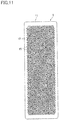
- the closed flame holes 12, i.e., the portions that are not actually drilled among the flame holes 12 formed in the first embodiment are represented by painting them black.
- the fourth row 16 4 , the twelfth row 16 12 , the twentieth row 16 20 , the twenty-eighth row 16 28 , and the thirty-sixth row 16 36 are made to be the selected rows as counted from one end (upper end as seen in FIG. 7 ) in the longitudinal direction of the plate main body 11.
- Twelve flame holes 12 positioned on the large equilateral hexagon 14 that encloses each of the unit flame hole groups belonging to each of the selected rows are all closed.
- the opening ratio of the flame holes 12 in the second embodiment is 32 %.
- the selected row there were selected the sixteenth row 16 16 , and the twenty-fourth row 16 24 , in addition to the selected rows according to the second embodiment. All of the twelve flame holes 12 that are positioned on the large equilateral hexagon 14 enclosing each of the unit flame hole groups belonging to each of these selected rows are closed.
- the opening ratio of the flame holes 12 in the third embodiment is 30 %.
- the fourth embodiment selection was made, as the selected rows, of the eighth row 16s and the thirty second row 16 32 , in addition to the selected rows according to the third embodiment so that three non-selected rows are present between each of the selected rows. All of the twelve flame holes 12 that are positioned on the large equilateral hexagon 14 enclosing each of the unit flame hole groups belonging to each of these selected rows are closed.
- the opening ratio of the flame holes 12 in the fourth embodiment is 28 %.
- three flame holes 12 positioned between the centers of each of the unit flame hole groups belonging to each of the first and the thirty-ninth rows 16 1 , 16 39 are also closed.
- the same rows as in the fourth embodiment were selected. But instead of all the flame holes 12 on the large equilateral hexagons 14 enclosing each of the unit flame hole groups belonging to each of these selected rows, a total of six flame holes 12 positioning in each of the corner portions of the equilateral hexagons 14 are closed.
- the two flame holes 12 that are near the respective unit flame hole groups are also closed.
- the opening ratio of the flame holes 12 in the fifth embodiment is 32 %.
- the flame holes 12 that are positioned in each of the corner portions of the large equilateral hexagons 14 enclosing each of the respective unit flame hole groups are closed.
- the opening ratio of the flame holes 12 in the sixth embodiment is 30 %.
- combustion tests were carried out by using the combustion plates 1 of the first embodiment - the sixth embodiment.
- the fuel gas was methane and the input (combustion amount) was 12 kW (2400 kW/m 2 when converted to calorific capacity for flame hole area).
- COaf which is the CO concentration in the theoretical dry combustion gas was measured.
- an arrangement was made in the tests such that the premixed gas of uniform excess air ratio was supplied to an entire region of the combustion plate 1. In the actual burners, however, due to lack of mixing between the fuel gas and the primary air, fluctuations occurred in the excess air ratio in the premixed gas at each part of the combustion plate 1.
- FIG. 13 shows the results of the combustion tests, in which line "a" is of the first embodiment, line b is of the second embodiment, line c is of the third embodiment, line d is of the fourth embodiment, line e is of the fifth embodiment, and line f is of the sixth embodiment.
- the lower limit of the range of excess air ratio ⁇ in which good combustion takes place in COaf ⁇ 400 ppm has been found to be about 1.12 in any of the first embodiment - the sixth embodiment, while the upper limits thereof have been found to be 1.42 in the first embodiment, 1.55 in the second embodiment, 1.60 in the third embodiment, 1.71 in the fourth embodiment, and 1.69 in the fifth embodiment and the sixth embodiment.
- combustion tests were carried out by using a combustion plate without providing the bottomed holes 15 and flame hole closing portions.
- the flames were aggregated and integrated with an increase in the input so as to become instable liftoff flames without the presence of stabilized flame portion at all. Combustion up to 9 kW was the limit and the combustion up to 12 kW was impossible.
- the first embodiment having bottomed holes 15 formed therein good combustion was possible even at 12 kW. From the above it can be seen that, due to the bottomed holes 15, there was obtained an effect of maintaining a stable flame in which the flame was prevented from being lifted off at the time of the above-mentioned high-load combustion.
- the flames come to be hardly lifted off, and the upper limit of the range of excess air ratio to perform good combustion becomes larger. From the above, it can be seen that recirculation region is generated by the flame hole closed portions, thereby enhancing the flame stabilizing effect.
- closure was made only of six flame holes 12 that are positioned in the corner portions of the equilateral hexagon.
- the upper limit of the range in the excess air ratio to perform good combustion becomes substantially the same as that of the fourth embodiment. From the above fact, it can be seen that, in order to enhance the effect of maintaining a stable flame and also in order to increase the opening ratio of the flame holes 12, the flame holes 12 that are positioned in each of the corner portions of the above-mentioned large equilateral hexagon need be closed. Further, although the opening ratio is the same (32 %) in the second embodiment and in the fifth embodiment, the range of excess air ratio in which good combustion can be performed is wider and superior in the fifth embodiment (line e in FIG. 13 ) than in the second embodiment (line b in FIG. 13 ).
- the diagonal direction of the equilateral hexagon 13 formed by six flame holes 12 of the unit flame hole group is defined as a row direction.
- closure is made of the flame holes 12 positioned in each of the corner portions of all the large equilateral hexagons 14 enclosing each of the unit flame hole groups belonging to the selected row.
- the result will be substantially the same as that of the sixth embodiment if the number of non-selected rows that are present between each of the selected rows is below two. Therefore, in order to prevent the occurrence of combustion resonant sounds, it is necessary to make the number of the non-selected rows present between each of the selected rows to be more than three as is the case in the second embodiment - the fifth embodiment.
- FIG. 14 shows the results at the input of 12 kW
- line b shows the results at the input of 13.8 kW
- line c in FIG. 14 shows the results of combustion tests performed by using the combustion plate described in Patent Document 1 as an example, and at the input of 12 kW.
- the range of excess air ratio ⁇ in which good combustion was performed at COaf - ⁇ 400ppm is found to be as narrow as 1.14 - 1.66 at the time of combustion of 13.8 kW as compared with 1.12 - 1.69 at the time of combustion of 12 kW, but is yet wider than 12 kW at the time of combustion of 12 kW in the example of the Patent Document 1.
- the flame opening ratio of the example in Patent Document 1 is 26 %
- the flame opening ratio of the fifth embodiment is as large as 32 %, and the load on the fan is reduced with the reduction in the fan noises.
- the seventh embodiment of the invention as shown in FIG. 16 .
- the opposing direction (longitudinal direction of the plate main body 11) of the upper and lower opposite sides, as seen in the figure, of the equilateral hexagon 13 to be formed by the six flame holes of the unit flame hole group is defined as the row direction.
- a plurality of rows at a predetermined distance from one another in a direction perpendicular to the row direction (direction of short sides of the plate main body 11) are selected, and closure is made of the flame holes 12 that are positioned in each of the corner portions of the large equilateral hexagon 14 enclosing each of the unit flame hole groups belonging to these selected rows.
- the arrangement in the seventh embodiment can obtain the effect of maintaining a stable flame of substantially the same degree as that in the fifth embodiment.
- the opposing direction of the opposite sides of the equilateral hexagon 13 to be formed by the six flame holes of the unit flame hole groups is defined as the row direction.
- closure is made of the flame holes 12 positioned in each of the corner portions of all the large equilateral hexagons 14 enclosing each of the unit flame hole groups belonging to the selected rows, if the number of the non-selected rows that are present between each of the selected rows is only one, the state will be substantially the same as that of the sixth embodiment, resulting in the generation of combustion resonant sounds.
- the seventh embodiment an arrangement has been made that selection is made of the first row 17 1 , the fourth row 17 4 , and the seventh row 17 7 as the selected rows as counted from one end of the short-side direction of the plate main body 11 (left end as seen in FIG. 16 ) so that two non-selected rows are present between each of the selected rows.
- the short-side direction of the plate main body 11, that is one of the diagonal directions of the equilateral hexagon 13 to be formed by the six flame holes of the unit flame hole group has been defined as the row direction.
- definition may be made such that the direction inclined by 60 degrees relative to the short-side direction of the plate main body 11, i.e., the other diagonal direction of the equilateral hexagon 13, may be defined as the row direction.
- the selected row is selected at a predetermined distance (such a distance that at least three non-selected rows are present between each of the selected rows) in a direction perpendicular to the row direction.
- closure may be made of at least part of the twelve flame holes that are positioned on the large equilateral hexagon enclosing each of the unit flame hole groups belonging to the selected row.
- the longitudinal direction which is one of the opposing directions of the opposite sides of the equilateral hexagon 13 to be formed by the six flame holes of the unit flame hole group, of the plate main body 11 is the row direction.
- the direction inclined by 30 degrees relative to the short-side direction that is the opposing direction of the other opposite sides of the equilateral hexagon 13 of the plate main body 11, may be defined as the row direction.
- selection may be made of the selected rows at a predetermined distance (at such a distance that at least two non-selected rows are present between each of the selected rows) perpendicular to the row direction out of the rows of the unit flame hole groups arrayed in this row direction. At least partial closure may thus be made of the flame holes that are positioned on the large equilateral hexagon enclosing each of the unit flame hole groups belonging to the selected rows.
- this invention was applied to the combustion plate 1 adapted to be used in a totally aerated combustion burner which is disposed in a heat source apparatus for supplying hot water or for heating space.
- the uses to which the burner of this invention is applied are not limited to the heat source apparatus, but this invention can be widely applied as a combustion plate for a totally aerated combustion burner in which combustion at a high load takes place.
Landscapes
- Engineering & Computer Science (AREA)
- Chemical & Material Sciences (AREA)
- Combustion & Propulsion (AREA)
- Mechanical Engineering (AREA)
- General Engineering & Computer Science (AREA)
- Gas Burners (AREA)
Claims (5)
- Verbrennungsplatte (1) für einen vollständig belüfteten Brenner, bei der eine Mehrzahl von Flammenaustrittsöffnungen (12) zum Ausstoßen eines vorgemischten Gases in einem aus Keramik ausgeführten Plattenhauptkörper (11) ausgebildet ist,
wobei die Flammenaustrittsöffnungen mit einem gleichen Durchmesser gleichmäßig über einer ganzen Oberfläche eines Verbrennungsbereichs des Plattenhauptkörpers mit einer derartigen Lagebeziehung ausgebildet sind, dass drei benachbarte Flammenaustrittsöffnungen ein gleichseitiges Dreieck bilden, und
wobei eine Vielzahl von Einheitsgruppen von Flammenaustrittsöffnungen definiert ist, von denen jede von sechs Flammenaustrittsöffnungen, die in einer Lagebeziehung angeordnet sind, um ein gleichseitiges Sechseck (13) zu bilden, und einer Flammenaustrittsöffnung in einem Zentrum derselben gebildet wird und angrenzend an eine andere Gruppe von Flammenaustrittsöffnungen über ein großes gleichseitiges Sechseck (14) angeordnet ist, das von einer Flammenaustrittsöffnung an jedem der Eckabschnitte des großen gleichseitigen Sechsecks (14) und einer Flammenaustrittsöffnung in einer Mitte von jeder der Seiten des großen gleichseitigen Sechsecks (14) gebildet wird, sodass das große gleichseitige Sechseck (14) diese Einheitsgruppe von Flammenaustrittsöffnungen umschließt,
wobei ein mit einem Boden versehenes Loch (15) derart in der Fläche des Plattenhauptkörpers ausgebildet ist,
dass es koaxial zur Flammenaustrittsöffnung im Zentrum von jeder der Einheitsgruppen von Flammenaustrittsöffnungen ist;
dass es kleiner als ein Durchmesser eines Kreises ist, der die sechs Flammenaustrittsöffnungen umschreibt, die sich in einer solchen Lagebeziehung befinden, dass sie das gleichseitige Sechseck (13) bilden; und
dass es größer als ein Durchmesser eines Kreises ist, der die sechs Flammenaustrittsöffnungen einbeschreibt, die sich in einer solchen Lagebeziehung befinden, dass sie das gleichseitige Sechseck (13) bilden,
wobei das vorgemischte Gas, das von den sechs Flammenaustrittsöffnungen ausgestoßen wird, die sich in einer solchen Lagebeziehung befinden, dass sie das gleichseitige Sechseck (13) bilden, eine Geschwindigkeitskomponente in Richtung eines Zentrums des mit einem Boden versehenen Lochs (15) aufweist;
dadurch gekennzeichnet, dass eine Reihenrichtung als eine vorbestimmte diagonale Richtung oder eine entgegengesetzte Richtung von vorbestimmten gegenüberliegenden Seiten des gleichseitigen Sechsecks (13) definiert ist, das von sechs Flammenaustrittsöffnungen in der Einheitsgruppe von Flammenaustrittsöffnungen gebildet werden soll, und
dass der Verschluss von mindestens einem Teil der Flammenaustrittsöffnungen von den zwölf Flammenaustrittsöffnungen bewerkstelligt wird, die auf dem großen gleichseitigen Sechseck (14) angeordnet sind, das jede der Einheitsgruppen von Flammenaustrittsöffnungen umschließt, die zu einer ausgewählten Reihe (16, 17) gehören, wobei die ausgewählte Reihe in einem vorbestimmten Abstand in einer zur Reihenrichtung perpendikularen Richtung aus den in der Reihenrichtung geordneten Einheitsgruppen von Flammenaustrittsöffnungen ausgewählt ist, und wobei der vorbestimmte Abstand derart eingestellt ist, dass, wenn die Reihenrichtung die diagonale Richtung ist, mindestens drei nicht gewählte Reihen (16) zwischen allen ausgewählten Reihen liegen, und dass, wenn die Reihenrichtung die entgegengesetzte Richtung der gegenüberliegenden Seiten ist, mindestens zwei nicht gewählte Reihen (17) zwischen allen ausgewählten Reihen liegen. - Verbrennungsplatte nach Anspruch 1, wobei eine Bodenfläche (15a) des mit einem Boden versehenen Lochs (15) derart ausgebildet ist, dass sie zu einem Zentrum desselben hin tiefer wird.
- Verbrennungsplatte nach Anspruch 1 oder 2, wobei das mit einem Boden versehene Loch (15) derart ausgebildet ist, dass sein Durchmesser zur Bodenfläche desselben hin kleiner wird.
- Verbrennungsplatte nach Anspruch 1 oder 2, wobei die Tiefe (h) des untersten Abschnitts im Randbereich des mit einem Boden versehenen Lochs (15) mehr als 1 mm und weniger als 3 mm beträgt.
- Verbrennungsplatte nach einem der Ansprüche 1 bis 4, wobei die Flammenaustrittsöffnungen (12), die geschlossen werden sollen, die Flammenaustrittsöffnungen sind, die an jedem der Eckabschnitte des großen gleichseitigen Sechsecks angeordnet sind.
Applications Claiming Priority (2)
| Application Number | Priority Date | Filing Date | Title |
|---|---|---|---|
| JP2009255778A JP5507966B2 (ja) | 2009-11-09 | 2009-11-09 | 燃焼プレート |
| PCT/JP2010/006155 WO2011055494A1 (ja) | 2009-11-09 | 2010-10-18 | 燃焼プレート |
Publications (3)
| Publication Number | Publication Date |
|---|---|
| EP2500644A1 EP2500644A1 (de) | 2012-09-19 |
| EP2500644A4 EP2500644A4 (de) | 2018-01-24 |
| EP2500644B1 true EP2500644B1 (de) | 2019-06-12 |
Family
ID=43969738
Family Applications (1)
| Application Number | Title | Priority Date | Filing Date |
|---|---|---|---|
| EP10828056.1A Not-in-force EP2500644B1 (de) | 2009-11-09 | 2010-10-18 | Verbrennungsplatte |
Country Status (8)
| Country | Link |
|---|---|
| US (1) | US9557055B2 (de) |
| EP (1) | EP2500644B1 (de) |
| JP (1) | JP5507966B2 (de) |
| KR (1) | KR101747290B1 (de) |
| CN (1) | CN102597623B (de) |
| AU (1) | AU2010316573B2 (de) |
| CA (1) | CA2779385C (de) |
| WO (1) | WO2011055494A1 (de) |
Families Citing this family (8)
| Publication number | Priority date | Publication date | Assignee | Title |
|---|---|---|---|---|
| JP5513425B2 (ja) * | 2011-03-02 | 2014-06-04 | リンナイ株式会社 | 燃焼プレート |
| KR101291627B1 (ko) * | 2011-10-14 | 2013-08-01 | 주식회사 경동나비엔 | 예혼합가스버너의 염공부 구조 |
| CN103851619B (zh) * | 2012-12-07 | 2016-11-23 | 青岛瑞迪燃气具制造有限公司 | 一种红外燃烧机燃烧板 |
| JP2016084955A (ja) * | 2014-10-24 | 2016-05-19 | リンナイ株式会社 | 燃焼プレート |
| CN104373937B (zh) * | 2014-11-13 | 2017-04-12 | 艾欧史密斯(中国)热水器有限公司 | 燃气预混燃烧器及燃气热水器 |
| JP6216365B2 (ja) * | 2015-12-28 | 2017-10-18 | 川崎重工業株式会社 | 平面燃焼バーナ用バーナプレート |
| JP6853075B2 (ja) * | 2017-03-13 | 2021-03-31 | リンナイ株式会社 | 全一次燃焼式バーナ |
| CN109737407B (zh) * | 2019-02-28 | 2020-01-17 | 山东省科学院能源研究所 | 一种微火焰式低氮燃烧器 |
Family Cites Families (31)
| Publication number | Priority date | Publication date | Assignee | Title |
|---|---|---|---|---|
| US3251396A (en) * | 1963-08-20 | 1966-05-17 | Corning Glass Works | Ceramic burner plate |
| US3558252A (en) * | 1968-07-29 | 1971-01-26 | Ind Del Hogar Sa | Radiating element |
| US3683058A (en) * | 1969-08-25 | 1972-08-08 | Maurice Partiot | Infrared burners and high efficiency radiant plates |
| CA969088A (en) * | 1971-12-21 | 1975-06-10 | Firma Schwank G.M.B.H. | Burner-plate for infra-red radiators |
| NL176301C (nl) * | 1974-08-24 | Schwank Gmbh | Toestel met ten minste een gasbrander voor een kookplaat. | |
| JPS5250036A (en) * | 1975-10-20 | 1977-04-21 | Rinnai Corp | Infrared gas combustion panel |
| JPS52137728A (en) * | 1976-05-13 | 1977-11-17 | Rinnai Kk | Gas infrared ray combustion plate |
| JPS6119297Y2 (de) * | 1980-05-02 | 1986-06-11 | ||
| JPS56162426A (en) | 1980-05-19 | 1981-12-14 | Toyo Electric Mfg Co Ltd | Method of operating vacuum contactor |
| JPS57129313A (en) * | 1981-02-03 | 1982-08-11 | Matsushita Electric Ind Co Ltd | Ceramic burner plate and manufacture thereof |
| WO1982002711A1 (fr) * | 1981-02-03 | 1982-08-19 | Mihara Toshihiro | Plaque ceramique de bruleur et procede de fabrication de celle-ci |
| JPS57129314A (en) * | 1981-02-03 | 1982-08-11 | Matsushita Electric Ind Co Ltd | Ceramic burner plate and manufacture thereof |
| FR2534353A1 (fr) * | 1982-10-11 | 1984-04-13 | Vaneecke Solaronics | Plaquette a face rayonnante alveolee pour bruleur radiant |
| JPS6082709A (ja) * | 1983-10-13 | 1985-05-10 | Matsushita Electric Ind Co Ltd | 赤外線バ−ナ |
| JPS62192019A (ja) | 1986-02-19 | 1987-08-22 | Canon Electronics Inc | 磁気ヘツド装置 |
| JPH0245616Y2 (de) * | 1986-05-22 | 1990-12-03 | ||
| JPH0759966B2 (ja) | 1991-02-21 | 1995-06-28 | リンナイ株式会社 | 燃焼プレート |
| SE468876B (sv) * | 1991-07-08 | 1993-04-05 | Staalhane Henrik | Anordning vid gaseldad grill |
| JPH0596722U (ja) * | 1992-05-27 | 1993-12-27 | サンデン株式会社 | 燃焼装置 |
| JP2768182B2 (ja) * | 1992-11-11 | 1998-06-25 | 三浦工業株式会社 | 予混合バーナ |
| JPH0759966A (ja) | 1993-08-23 | 1995-03-07 | Yamato Sewing Mach Co Ltd | ラベル供給装置 |
| DE19901145A1 (de) * | 1999-01-14 | 2000-07-20 | Krieger Gmbh & Co Kg | Als Flächenstrahler ausgebildeter Infrarot-Strahler |
| GB9929257D0 (en) * | 1999-12-11 | 2000-02-02 | Bray Technologies Plc | Improved burner plaque |
| JP2001182908A (ja) * | 1999-12-22 | 2001-07-06 | Tokyo Gas Co Ltd | 低NOxバーナおよび低NOxバーナの燃焼方法 |
| EP1476696A1 (de) * | 2002-02-12 | 2004-11-17 | Voith Paper Patent GmbH | Als flächenstrahler ausgebildeter infrarot-strahler |
| US6619280B1 (en) * | 2002-05-30 | 2003-09-16 | Dongsheng Zhou | Converging flame burner |
| JP4754414B2 (ja) * | 2006-06-12 | 2011-08-24 | リンナイ株式会社 | 燃焼装置 |
| JP4730743B2 (ja) * | 2006-11-30 | 2011-07-20 | リンナイ株式会社 | 全一次燃焼式バーナ |
| US8919336B2 (en) * | 2007-08-03 | 2014-12-30 | Solarflo Corporation | Radiant gas burner unit |
| JP4898612B2 (ja) * | 2007-09-14 | 2012-03-21 | リンナイ株式会社 | 燃焼板式バーナ |
| CA136106S (en) * | 2009-12-25 | 2011-03-14 | Rinnai Kk | Burner plate |
-
2009
- 2009-11-09 JP JP2009255778A patent/JP5507966B2/ja active Active
-
2010
- 2010-10-18 EP EP10828056.1A patent/EP2500644B1/de not_active Not-in-force
- 2010-10-18 CN CN201080050734.0A patent/CN102597623B/zh not_active Expired - Fee Related
- 2010-10-18 AU AU2010316573A patent/AU2010316573B2/en not_active Ceased
- 2010-10-18 US US13/504,298 patent/US9557055B2/en active Active
- 2010-10-18 KR KR1020127011007A patent/KR101747290B1/ko active Active
- 2010-10-18 WO PCT/JP2010/006155 patent/WO2011055494A1/ja not_active Ceased
- 2010-10-18 CA CA2779385A patent/CA2779385C/en not_active Expired - Fee Related
Non-Patent Citations (1)
| Title |
|---|
| None * |
Also Published As
| Publication number | Publication date |
|---|---|
| CN102597623B (zh) | 2014-04-23 |
| EP2500644A4 (de) | 2018-01-24 |
| AU2010316573B2 (en) | 2014-10-09 |
| AU2010316573A1 (en) | 2012-05-24 |
| CN102597623A (zh) | 2012-07-18 |
| US9557055B2 (en) | 2017-01-31 |
| EP2500644A1 (de) | 2012-09-19 |
| US20120214111A1 (en) | 2012-08-23 |
| JP2011099646A (ja) | 2011-05-19 |
| KR20120116391A (ko) | 2012-10-22 |
| WO2011055494A1 (ja) | 2011-05-12 |
| CA2779385A1 (en) | 2011-05-12 |
| JP5507966B2 (ja) | 2014-05-28 |
| KR101747290B1 (ko) | 2017-06-14 |
| CA2779385C (en) | 2017-07-11 |
Similar Documents
| Publication | Publication Date | Title |
|---|---|---|
| CA2779385C (en) | Combustion plate | |
| US8511092B2 (en) | Dimpled/grooved face on a fuel injection nozzle body for flame stabilization and related method | |
| EP3012526B1 (de) | Verbrennungsplatte | |
| JP3814604B2 (ja) | 多段制御を具現するガス燃焼バーナ | |
| EP2815180B1 (de) | Gestufte sauerstoff-brennstoff brenner und verfahren zu deren nutzung | |
| KR100495505B1 (ko) | 다단제어를 구현하는 가스연소 버너 | |
| US7647898B2 (en) | Boiler and low-NOx combustion method | |
| US20030138749A1 (en) | Burner plaque | |
| AU2012224388B2 (en) | Combustion plate | |
| KR101291627B1 (ko) | 예혼합가스버너의 염공부 구조 | |
| KR100566806B1 (ko) | 다화염 예혼합 버너 | |
| US20250155121A1 (en) | Compact low emissions burner nozzle using additive manufacturing | |
| JPH09145024A (ja) | 角型先混合バーナ | |
| EP3985339B1 (de) | Verbrennungswärmeerzeuger mit rezirkulationsbereich | |
| CN119245027A (zh) | 用于燃烧器的分气盘、燃烧器及燃气灶 | |
| JPH0137646B2 (de) | ||
| JPS62276311A (ja) | ラインバ−ナ | |
| JPH08320109A (ja) | 燃焼プレート | |
| JPH0684121U (ja) | 低NOxバーナ | |
| JPH05187611A (ja) | 衝突燃焼装置 | |
| KR20040035372A (ko) | 예혼합 가스연소 버너용 매니폴더 구조 | |
| JPH0561617U (ja) | 燃焼装置 | |
| JPH0684120U (ja) | 低NOxバーナ | |
| JPS63187014A (ja) | バ−ナ |
Legal Events
| Date | Code | Title | Description |
|---|---|---|---|
| PUAI | Public reference made under article 153(3) epc to a published international application that has entered the european phase |
Free format text: ORIGINAL CODE: 0009012 |
|
| 17P | Request for examination filed |
Effective date: 20120508 |
|
| AK | Designated contracting states |
Kind code of ref document: A1 Designated state(s): AL AT BE BG CH CY CZ DE DK EE ES FI FR GB GR HR HU IE IS IT LI LT LU LV MC MK MT NL NO PL PT RO RS SE SI SK SM TR |
|
| DAX | Request for extension of the european patent (deleted) | ||
| RA4 | Supplementary search report drawn up and despatched (corrected) |
Effective date: 20171222 |
|
| RIC1 | Information provided on ipc code assigned before grant |
Ipc: F23D 14/02 20060101AFI20171218BHEP |
|
| GRAP | Despatch of communication of intention to grant a patent |
Free format text: ORIGINAL CODE: EPIDOSNIGR1 |
|
| STAA | Information on the status of an ep patent application or granted ep patent |
Free format text: STATUS: GRANT OF PATENT IS INTENDED |
|
| INTG | Intention to grant announced |
Effective date: 20181218 |
|
| GRAS | Grant fee paid |
Free format text: ORIGINAL CODE: EPIDOSNIGR3 |
|
| GRAA | (expected) grant |
Free format text: ORIGINAL CODE: 0009210 |
|
| STAA | Information on the status of an ep patent application or granted ep patent |
Free format text: STATUS: THE PATENT HAS BEEN GRANTED |
|
| AK | Designated contracting states |
Kind code of ref document: B1 Designated state(s): AL AT BE BG CH CY CZ DE DK EE ES FI FR GB GR HR HU IE IS IT LI LT LU LV MC MK MT NL NO PL PT RO RS SE SI SK SM TR |
|
| REG | Reference to a national code |
Ref country code: GB Ref legal event code: FG4D |
|
| REG | Reference to a national code |
Ref country code: CH Ref legal event code: EP |
|
| REG | Reference to a national code |
Ref country code: AT Ref legal event code: REF Ref document number: 1143034 Country of ref document: AT Kind code of ref document: T Effective date: 20190615 |
|
| REG | Reference to a national code |
Ref country code: DE Ref legal event code: R096 Ref document number: 602010059446 Country of ref document: DE |
|
| REG | Reference to a national code |
Ref country code: IE Ref legal event code: FG4D |
|
| REG | Reference to a national code |
Ref country code: NL Ref legal event code: FP |
|
| REG | Reference to a national code |
Ref country code: LT Ref legal event code: MG4D |
|
| PG25 | Lapsed in a contracting state [announced via postgrant information from national office to epo] |
Ref country code: LT Free format text: LAPSE BECAUSE OF FAILURE TO SUBMIT A TRANSLATION OF THE DESCRIPTION OR TO PAY THE FEE WITHIN THE PRESCRIBED TIME-LIMIT Effective date: 20190612 Ref country code: HR Free format text: LAPSE BECAUSE OF FAILURE TO SUBMIT A TRANSLATION OF THE DESCRIPTION OR TO PAY THE FEE WITHIN THE PRESCRIBED TIME-LIMIT Effective date: 20190612 Ref country code: SE Free format text: LAPSE BECAUSE OF FAILURE TO SUBMIT A TRANSLATION OF THE DESCRIPTION OR TO PAY THE FEE WITHIN THE PRESCRIBED TIME-LIMIT Effective date: 20190612 Ref country code: NO Free format text: LAPSE BECAUSE OF FAILURE TO SUBMIT A TRANSLATION OF THE DESCRIPTION OR TO PAY THE FEE WITHIN THE PRESCRIBED TIME-LIMIT Effective date: 20190912 Ref country code: AL Free format text: LAPSE BECAUSE OF FAILURE TO SUBMIT A TRANSLATION OF THE DESCRIPTION OR TO PAY THE FEE WITHIN THE PRESCRIBED TIME-LIMIT Effective date: 20190612 Ref country code: FI Free format text: LAPSE BECAUSE OF FAILURE TO SUBMIT A TRANSLATION OF THE DESCRIPTION OR TO PAY THE FEE WITHIN THE PRESCRIBED TIME-LIMIT Effective date: 20190612 Ref country code: ES Free format text: LAPSE BECAUSE OF FAILURE TO SUBMIT A TRANSLATION OF THE DESCRIPTION OR TO PAY THE FEE WITHIN THE PRESCRIBED TIME-LIMIT Effective date: 20190612 |
|
| PG25 | Lapsed in a contracting state [announced via postgrant information from national office to epo] |
Ref country code: BG Free format text: LAPSE BECAUSE OF FAILURE TO SUBMIT A TRANSLATION OF THE DESCRIPTION OR TO PAY THE FEE WITHIN THE PRESCRIBED TIME-LIMIT Effective date: 20190912 Ref country code: LV Free format text: LAPSE BECAUSE OF FAILURE TO SUBMIT A TRANSLATION OF THE DESCRIPTION OR TO PAY THE FEE WITHIN THE PRESCRIBED TIME-LIMIT Effective date: 20190612 Ref country code: RS Free format text: LAPSE BECAUSE OF FAILURE TO SUBMIT A TRANSLATION OF THE DESCRIPTION OR TO PAY THE FEE WITHIN THE PRESCRIBED TIME-LIMIT Effective date: 20190612 Ref country code: GR Free format text: LAPSE BECAUSE OF FAILURE TO SUBMIT A TRANSLATION OF THE DESCRIPTION OR TO PAY THE FEE WITHIN THE PRESCRIBED TIME-LIMIT Effective date: 20190913 |
|
| REG | Reference to a national code |
Ref country code: AT Ref legal event code: MK05 Ref document number: 1143034 Country of ref document: AT Kind code of ref document: T Effective date: 20190612 |
|
| PG25 | Lapsed in a contracting state [announced via postgrant information from national office to epo] |
Ref country code: SK Free format text: LAPSE BECAUSE OF FAILURE TO SUBMIT A TRANSLATION OF THE DESCRIPTION OR TO PAY THE FEE WITHIN THE PRESCRIBED TIME-LIMIT Effective date: 20190612 Ref country code: RO Free format text: LAPSE BECAUSE OF FAILURE TO SUBMIT A TRANSLATION OF THE DESCRIPTION OR TO PAY THE FEE WITHIN THE PRESCRIBED TIME-LIMIT Effective date: 20190612 Ref country code: AT Free format text: LAPSE BECAUSE OF FAILURE TO SUBMIT A TRANSLATION OF THE DESCRIPTION OR TO PAY THE FEE WITHIN THE PRESCRIBED TIME-LIMIT Effective date: 20190612 Ref country code: EE Free format text: LAPSE BECAUSE OF FAILURE TO SUBMIT A TRANSLATION OF THE DESCRIPTION OR TO PAY THE FEE WITHIN THE PRESCRIBED TIME-LIMIT Effective date: 20190612 Ref country code: CZ Free format text: LAPSE BECAUSE OF FAILURE TO SUBMIT A TRANSLATION OF THE DESCRIPTION OR TO PAY THE FEE WITHIN THE PRESCRIBED TIME-LIMIT Effective date: 20190612 Ref country code: PT Free format text: LAPSE BECAUSE OF FAILURE TO SUBMIT A TRANSLATION OF THE DESCRIPTION OR TO PAY THE FEE WITHIN THE PRESCRIBED TIME-LIMIT Effective date: 20191014 |
|
| PG25 | Lapsed in a contracting state [announced via postgrant information from national office to epo] |
Ref country code: SM Free format text: LAPSE BECAUSE OF FAILURE TO SUBMIT A TRANSLATION OF THE DESCRIPTION OR TO PAY THE FEE WITHIN THE PRESCRIBED TIME-LIMIT Effective date: 20190612 Ref country code: IS Free format text: LAPSE BECAUSE OF FAILURE TO SUBMIT A TRANSLATION OF THE DESCRIPTION OR TO PAY THE FEE WITHIN THE PRESCRIBED TIME-LIMIT Effective date: 20191012 |
|
| REG | Reference to a national code |
Ref country code: DE Ref legal event code: R097 Ref document number: 602010059446 Country of ref document: DE |
|
| PG25 | Lapsed in a contracting state [announced via postgrant information from national office to epo] |
Ref country code: TR Free format text: LAPSE BECAUSE OF FAILURE TO SUBMIT A TRANSLATION OF THE DESCRIPTION OR TO PAY THE FEE WITHIN THE PRESCRIBED TIME-LIMIT Effective date: 20190612 |
|
| PLBE | No opposition filed within time limit |
Free format text: ORIGINAL CODE: 0009261 |
|
| STAA | Information on the status of an ep patent application or granted ep patent |
Free format text: STATUS: NO OPPOSITION FILED WITHIN TIME LIMIT |
|
| PG25 | Lapsed in a contracting state [announced via postgrant information from national office to epo] |
Ref country code: PL Free format text: LAPSE BECAUSE OF FAILURE TO SUBMIT A TRANSLATION OF THE DESCRIPTION OR TO PAY THE FEE WITHIN THE PRESCRIBED TIME-LIMIT Effective date: 20190612 Ref country code: DK Free format text: LAPSE BECAUSE OF FAILURE TO SUBMIT A TRANSLATION OF THE DESCRIPTION OR TO PAY THE FEE WITHIN THE PRESCRIBED TIME-LIMIT Effective date: 20190612 |
|
| REG | Reference to a national code |
Ref country code: DE Ref legal event code: R119 Ref document number: 602010059446 Country of ref document: DE |
|
| 26N | No opposition filed |
Effective date: 20200313 |
|
| PG25 | Lapsed in a contracting state [announced via postgrant information from national office to epo] |
Ref country code: SI Free format text: LAPSE BECAUSE OF FAILURE TO SUBMIT A TRANSLATION OF THE DESCRIPTION OR TO PAY THE FEE WITHIN THE PRESCRIBED TIME-LIMIT Effective date: 20190612 Ref country code: IS Free format text: LAPSE BECAUSE OF FAILURE TO SUBMIT A TRANSLATION OF THE DESCRIPTION OR TO PAY THE FEE WITHIN THE PRESCRIBED TIME-LIMIT Effective date: 20200224 Ref country code: MC Free format text: LAPSE BECAUSE OF FAILURE TO SUBMIT A TRANSLATION OF THE DESCRIPTION OR TO PAY THE FEE WITHIN THE PRESCRIBED TIME-LIMIT Effective date: 20190612 |
|
| REG | Reference to a national code |
Ref country code: CH Ref legal event code: PL |
|
| PG2D | Information on lapse in contracting state deleted |
Ref country code: IS |
|
| PG25 | Lapsed in a contracting state [announced via postgrant information from national office to epo] |
Ref country code: CH Free format text: LAPSE BECAUSE OF NON-PAYMENT OF DUE FEES Effective date: 20191031 Ref country code: DE Free format text: LAPSE BECAUSE OF NON-PAYMENT OF DUE FEES Effective date: 20200501 Ref country code: LI Free format text: LAPSE BECAUSE OF NON-PAYMENT OF DUE FEES Effective date: 20191031 Ref country code: LU Free format text: LAPSE BECAUSE OF NON-PAYMENT OF DUE FEES Effective date: 20191018 |
|
| REG | Reference to a national code |
Ref country code: BE Ref legal event code: MM Effective date: 20191031 |
|
| PG25 | Lapsed in a contracting state [announced via postgrant information from national office to epo] |
Ref country code: BE Free format text: LAPSE BECAUSE OF NON-PAYMENT OF DUE FEES Effective date: 20191031 |
|
| PG25 | Lapsed in a contracting state [announced via postgrant information from national office to epo] |
Ref country code: FR Free format text: LAPSE BECAUSE OF NON-PAYMENT OF DUE FEES Effective date: 20191031 Ref country code: IE Free format text: LAPSE BECAUSE OF NON-PAYMENT OF DUE FEES Effective date: 20191018 |
|
| PGFP | Annual fee paid to national office [announced via postgrant information from national office to epo] |
Ref country code: NL Payment date: 20201028 Year of fee payment: 11 |
|
| PGFP | Annual fee paid to national office [announced via postgrant information from national office to epo] |
Ref country code: GB Payment date: 20201022 Year of fee payment: 11 Ref country code: IT Payment date: 20201026 Year of fee payment: 11 |
|
| PG25 | Lapsed in a contracting state [announced via postgrant information from national office to epo] |
Ref country code: CY Free format text: LAPSE BECAUSE OF FAILURE TO SUBMIT A TRANSLATION OF THE DESCRIPTION OR TO PAY THE FEE WITHIN THE PRESCRIBED TIME-LIMIT Effective date: 20190612 |
|
| PG25 | Lapsed in a contracting state [announced via postgrant information from national office to epo] |
Ref country code: MT Free format text: LAPSE BECAUSE OF FAILURE TO SUBMIT A TRANSLATION OF THE DESCRIPTION OR TO PAY THE FEE WITHIN THE PRESCRIBED TIME-LIMIT Effective date: 20190612 Ref country code: HU Free format text: LAPSE BECAUSE OF FAILURE TO SUBMIT A TRANSLATION OF THE DESCRIPTION OR TO PAY THE FEE WITHIN THE PRESCRIBED TIME-LIMIT; INVALID AB INITIO Effective date: 20101018 |
|
| REG | Reference to a national code |
Ref country code: NL Ref legal event code: MM Effective date: 20211101 |
|
| GBPC | Gb: european patent ceased through non-payment of renewal fee |
Effective date: 20211018 |
|
| PG25 | Lapsed in a contracting state [announced via postgrant information from national office to epo] |
Ref country code: MK Free format text: LAPSE BECAUSE OF FAILURE TO SUBMIT A TRANSLATION OF THE DESCRIPTION OR TO PAY THE FEE WITHIN THE PRESCRIBED TIME-LIMIT Effective date: 20190612 |
|
| PG25 | Lapsed in a contracting state [announced via postgrant information from national office to epo] |
Ref country code: NL Free format text: LAPSE BECAUSE OF NON-PAYMENT OF DUE FEES Effective date: 20211101 Ref country code: GB Free format text: LAPSE BECAUSE OF NON-PAYMENT OF DUE FEES Effective date: 20211018 |
|
| PG25 | Lapsed in a contracting state [announced via postgrant information from national office to epo] |
Ref country code: IT Free format text: LAPSE BECAUSE OF NON-PAYMENT OF DUE FEES Effective date: 20211018 |