EP2500596B1 - Protecteur de surcouple pour compresseur de climatisation - Google Patents
Protecteur de surcouple pour compresseur de climatisation Download PDFInfo
- Publication number
- EP2500596B1 EP2500596B1 EP12157706.8A EP12157706A EP2500596B1 EP 2500596 B1 EP2500596 B1 EP 2500596B1 EP 12157706 A EP12157706 A EP 12157706A EP 2500596 B1 EP2500596 B1 EP 2500596B1
- Authority
- EP
- European Patent Office
- Prior art keywords
- compressor
- over
- torque
- accessory drive
- feature
- Prior art date
- Legal status (The legal status is an assumption and is not a legal conclusion. Google has not performed a legal analysis and makes no representation as to the accuracy of the status listed.)
- Not-in-force
Links
Images


Classifications
-
- F—MECHANICAL ENGINEERING; LIGHTING; HEATING; WEAPONS; BLASTING
- F16—ENGINEERING ELEMENTS AND UNITS; GENERAL MEASURES FOR PRODUCING AND MAINTAINING EFFECTIVE FUNCTIONING OF MACHINES OR INSTALLATIONS; THERMAL INSULATION IN GENERAL
- F16D—COUPLINGS FOR TRANSMITTING ROTATION; CLUTCHES; BRAKES
- F16D9/00—Couplings with safety member for disconnecting, e.g. breaking or melting member
- F16D9/06—Couplings with safety member for disconnecting, e.g. breaking or melting member by breaking due to shear stress
-
- F—MECHANICAL ENGINEERING; LIGHTING; HEATING; WEAPONS; BLASTING
- F16—ENGINEERING ELEMENTS AND UNITS; GENERAL MEASURES FOR PRODUCING AND MAINTAINING EFFECTIVE FUNCTIONING OF MACHINES OR INSTALLATIONS; THERMAL INSULATION IN GENERAL
- F16D—COUPLINGS FOR TRANSMITTING ROTATION; CLUTCHES; BRAKES
- F16D27/00—Magnetically- or electrically- actuated clutches; Control or electric circuits therefor
- F16D27/10—Magnetically- or electrically- actuated clutches; Control or electric circuits therefor with an electromagnet not rotating with a clutching member, i.e. without collecting rings
- F16D27/108—Magnetically- or electrically- actuated clutches; Control or electric circuits therefor with an electromagnet not rotating with a clutching member, i.e. without collecting rings with axially movable clutching members
- F16D27/112—Magnetically- or electrically- actuated clutches; Control or electric circuits therefor with an electromagnet not rotating with a clutching member, i.e. without collecting rings with axially movable clutching members with flat friction surfaces, e.g. discs
Definitions
- the invention generally relates to an automotive air conditioner equipped with a clutch, and more particularly relates to an automotive air conditioner compressor with an over-torque protection device for protecting an accessory drive.
- an automotive air-conditioning system serves to maintain the interior temperature of an automobile below an outside temperature through a cyclic operation of compression, condensation, expansion and evaporation of refrigerant.
- the above cyclic operation generally requires a compressor, a condenser, an expansion valve and an evaporator.
- the compressor is typically powered by an accessory drive.
- the compressor may be a fixed displacement or a variable displacement type compressor.
- the compressor operation may be controlled by an engagement or disengagement of a clutch, depending on the conditions of the system.
- the clutch is typically located between the accessory drive and the compressor.
- the clutch typically incorporates a pulley that engages an accessory drive belt.
- the type of clutch most often used in automotive air conditioner compressor applications is an electromagnetic clutch, although mechanical, hydraulic or other clutch types could also be used.
- An electromagnetic clutch is usually preferred due to ease of packaging and control.
- An electromagnetic clutch typically operates by using an electromagnet to hold an armature to a rotor. In many automotive air conditioners, the armature is attached to the compressor and the rotor is attached to the accessory drive. Some compressors engage and disengage the clutch to cycle the automotive air conditioner compressor on and off as needed.
- an over-torque condition may occur when the normal operating torque of the compressor is exceeded due to a mechanical problem in the compressor, such as a bearing seizing.
- Some automotive air conditioner compressors that are equipped with clutches are also configured to stop coupling torque between an accessory drive and the compressor if the compressor causes an over torque condition on the accessory drive. This is desirable, as for instance disclosed in EP1681484 , to avoid damage to the accessory drive that may render other components connected to the accessory drive, such as an alternator or coolant pump, inoperative.
- the torque applied to the clutch may exceed the ability of the magnetic field from the rotor to hold the armature in place.
- the torque from the accessory drive may cause the rotor to slip and rotate relative to the armature.
- Heat may be generated by the friction between the armature and rotor. If the clutch is not disengaged, heat generated by friction could damage the accessory drive belt or the clutch bearings.
- an electromagnetic clutch can be disengaged to decouple the compressor from the accessory drive when an over-torque condition occurs. Excessive heat generated by friction between the rotor and armature may cause a thermal fuse to open and de-energize the coil 24.
- a thermal sensor may detect excessive heat and trigger an electronic compressor controller to de-energize the coil 24.
- a motion sensor can detect that the compressor has stopped rotating or that a speed differential exists between the compressor and accessory drive and provide an indication for an electronic compressor controller to de-energize the coil 24.
- thermal fuse may not quickly disengage the clutch to decouple the compressor from the accessory drive because of the time needed for friction to generate excessive heat.
- the typical time required for a thermal fuse to open for an over-torque condition event may be 50 to 80 seconds. If the accessory drive pulley 18 has a low engagement percentage, the accessory drive pulley may experience belt slip during an over-torque condition before slip between the armature and rotor occurs. In these cases, the accessory drive belt may be damaged before the thermal fuse opens. Therefore, a thermal fuse is not preferred for these applications.
- thermal sensors may not quickly disengage the clutch to decouple the compressor from the accessory drive because of the time needed for friction to generate excessive heat.
- a motion detector may not quickly disengage the clutch to decouple the compressor from the accessory drive due to the time required to detect that the compressor has stopped rotating or that a speed differential exists between the compressor and accessory drive.
- thermal sensors and motion sensors are more expensive than thermal fuses and additionally require electrical connections to an electronic controller, and so are also not preferred.
- an automotive air conditioning compressor assembly includes a compressor, a clutch, and an over-torque protection device.
- the compressor is operable to compress material within the compressor.
- the compressor is capable of exhibiting an over-torque condition.
- the clutch is operable to an engaged state wherein an accessory drive is coupled to the compressor, by urging an armature and a rotor together, for operating the compressor, and operable to a disengaged state.
- the over-torque protection device is interposed between the compressor and the accessory drive. The over-torque protection device configured to decouple the compressor and the accessory drive when the over-torque condition occurs.
- the compressor assembly further comprises a frangible element adapted to break when the over-torque condition occurs to mechanically decouple the compressor and the accessory drive.
- the compressor assembly further comprises a ramp coupled to the frangible element and a lifting feature coupled to the accessory drive.
- the ramp defines a helical ridge
- the lifting feature defines a lifting ridge engaging the helical ridge, wherein when the frangible element breaks, relative rotation between the lifting feature and the ramp urges the armature and the rotor apart to decouple the compressor and the accessory drive.
- the compressor assembly further comprises an over-rotation feature coupled to the frangible element wherein the over-rotation feature limits the relative rotation of the lifting feature to less than one rotation after the frangible element has broken.
- the compressor assembly further comprises a locking feature that prevents counter-rotation of the lifting feature after relative rotation between the lifting feature and the ramp has urged the armature and the rotor apart to decouple the compressor and the accessory drive.
- the locking feature comprises a notch on the leading edge of the ramp that engages the trailing edge of the lifting feature.
- the frangible element comprises spokes are adapted to break when the frangible element is subjected to torque loads greater than a torque threshold indicative of the over-torque condition and the spokes are embossed to be a controlled thickness, so as to more precisely define a reaction torque.
- a clutch assembly for use with an automotive air conditioning compressor.
- the clutch is operable to an engaged state wherein an accessory drive is coupled to the compressor for operating the compressor, and operable to a disengaged state.
- An over-torque protection device interposed between the compressor and the accessory drive is configured to decouple the compressor and the accessory drive when the over-torque condition occurs.
- the clutch assembly further comprises a frangible element adapted to break when the over-torque condition occurs to mechanically decouple the compressor and the accessory drive.
- the clutch operates to the engaged state by urging an armature and a rotor together
- the clutch assembly further comprises a ramp coupled to the compressor and a lifting feature coupled to the accessory drive, wherein the ramp defines a helical ridge, and the lifting feature defines a lifting ridge engaging the helical ridge, wherein when the frangible element breaks, relative rotation between the lifting feature and the ramp urges the armature and the rotor apart to decouple the compressor and the accessory drive.
- the clutch assembly further comprises an over-rotation feature, wherein the over-rotation feature limits the relative rotation of the lifting feature to less than one rotation after the frangible element has broken.
- the clutch assembly further comprises a locking feature that prevents counter-rotation of the lifting feature after relative rotation between the lifting feature and the ramp has urged the armature and the rotor apart to decouple the compressor and the accessory drive.
- the locking feature comprises a notch on the leading edge of the ramp that engages the trailing edge of the lifting feature and, the frangible element comprises spokes, wherein said spokes are adapted to break when the frangible element is subjected to torque loads greater than a torque threshold indicative of the over-torque condition.
- the spokes are embossed to be a controlled thickness, so as to more precisely define a reaction torque.
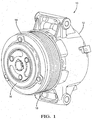
- Fig. 1 illustrates a compressor 12 that compresses material, in this case refrigerant, within the compressor 12.
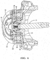
- the compressor 12 includes an input shaft 13 ( Fig. 6 ) to provide mechanical energy to operate the compressor 12.
- the input shaft 13 is coupled to an accessory drive (not shown) which provides mechanical energy to the compressor.
- a non-limiting example of an accessory drive is a serpentine belt, sometimes called a fan belt, that transfers mechanical energy from an automobile engine.
- the compressor 12 may include a clutch 14 coupled to the input shaft 13 and interposed between the input shaft 13 and the accessory drive.
- the clutch 14 may include an accessory drive pulley 18 that may be coupled to the accessory drive belt (not shown).
- the clutch 14 may be operable to an engaged state wherein the accessory drive is coupled to the input shaft 13 for operating the compressor 12. Alternately, the clutch 14 may be operable to a disengaged state wherein the input shaft 13 is decoupled from the accessory drive.
- the compressor 12 may be a fixed displacement compressor or a variable displacement compressor.
- the compressor 12 may be capable of exhibiting an over-torque condition.
- Conditions that may cause the compressor 12 to exhibit an over-torque condition include, but are not limited to, a bearing failure or a piston seizure within the compressor 12.
- An over-torque condition may cause the input shaft 13 to transfer an increased mechanical load onto the accessory drive leading to an over-torque condition on the accessory drive coupled to the clutch 14:
- the over-torque condition may cause the clutch 14 to slip internally or may cause the accessory drive belt to slip on the accessory drive pulley 18. Either of these slip conditions may cause damage to the accessory drive.
- the assembly 10 may also include an over-torque protection device 16, which may be interposed between the compressor and the accessory drive.
- the over-torque protection device 16 may be configured to decouple the compressor 12 and the accessory drive when the over-torque condition occurs.
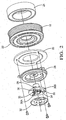
- Fig. 2 illustrates an embodiment of an over-torque protection device 16 that includes a frangible element 30 that may mechanically fracture during over-torque conditions to quickly decouple the compressor 12 from the accessory drive.
- the frangible element 30 comprises an annular inner section 30A coupled to the input shaft 13, and an annular outer section 30B, coupled to an armature 20 that is coplanar and concentric with the inner section 30A.
- the frangible element 30 may include a plurality of spokes 34 formed in the frangible element 30 that define radial slots 33 and couples the inner section 30A to the outer section 30B.
- the torque applied to frangible element 30 by the clutch 14 from the accessory drive may cause the spokes 34 to fracture and mechanically decouple the inner section 30A from the outer section 30B, thereby quickly decoupling the compressor 12 from the accessory drive.
- the spokes 34 may be embossed to achieve a controlled thickness, so as to more precisely determine the reaction torque between the accessory drive pulley 18 and the input shaft 13 that will break the frangible element 30 and result in quickly decoupling of the accessory drive pulley 18 from the input shaft 13.
- the frangible element 30 may be made from a powdered metal, such as iron, copper, or copper infiltrated steel.
- the thickness of the frangible element 30 may be 4 to 7 mm and the cross sectional area of the spokes 34 may be 15 to 20 mm 2 at a radius 12 to 16 mm from the center of the input shaft 13. It will be appreciated that the spoke thickness and spoke width may depend on the material used to manufacture the frangible element 30, the radial location of the spokes 34 on the frangible element 30, the diameter of the accessory drive pulley 18, and the percentage of the accessory drive pulley 18 contacting the accessory drive belt, as well as other factors.
- the frangible element may be a shear pin (not shown) that couples a hub, affixed to the armature 20, to the input shaft 13.
- the shear pin is configured to break during over-torque conditions to disconnect the hub from the input shaft 13, thereby disconnecting the compressor 12 from the accessory drive.
- the hub and input shaft 13 may not be fully decoupled as there may still be residual torque and/or heat generation due to the friction between the hub and input shaft 13 that are still in mechanical contact even though no longer coupled.
- the frangible element may be a breakaway input shaft (not shown) which has a predetermined break point in the input shaft 13 that is located between a hub that is fixed to the armature 20 and the compressor 12.
- the input shaft 13 is configured to break at the predetermined break point when an over-torque condition occurs, thereby disconnecting the compressor 12 from the accessory drive.
- the breakaway shaft suffers from the same disadvantage as the shear pin in that the hub and input shaft 13 may not be fully decoupled and there may still be residual torque and/or heat generation caused by parts rubbing against each other.
- the over-torque protection device could alternately include a mechanical release device.
- the method of separating the torque from the accessory drive to the compressor is accomplished by the means of a spring, cam, hook, ratchet, or gears to name only a few methods that could be used as a mechanical release. While such devices may provide resettable over-torque protection, the cost and complexity of such a solution is undesirable in view of the general rarity of an over-torque condition.
- the clutch 14 operates to the engaged state by urging an armature 20 and a rotor 22 together via magnetic force from a magnetic field generated in the rotor by an electric current flowing through coil 24, see Fig. 2 .
- the clutch 14 is disengaged when electric current stops flowing through the coil 24 and the magnetic field collapses.
- the over-torque protection device 16 disengages the clutch 14 by exerting an axial mechanical force in opposition to the magnetic force and of sufficient magnitude to overcome the magnetic force and urge the armature 20 and rotor 22 apart.
- Fig. 2 illustrates an embodiment of an over-torque protection device 16 that includes a lifting feature 26 configured to urge the armature 20 and rotor 22 apart when an over-torque condition occurs to quickly decouple the compressor 12 from the accessory drive.
- the lifting feature 26 defines a lifting ridge 42.
- the lifting feature 26 is coupled to the outer section 30B of the frangible element 30.
- the lifting ridge 42 may be generally coplanar with the armature 20.
- a ramp 28 defines a helical ridge 38.
- the ramp 28 is coupled to the inner section 30A of the frangible element 30.
- the embodiment of the lifting feature 26 illustrated in Fig. 2 incorporates an annular ring torque cushion configured to mitigate shock to the compressor assembly during normal clutch engagement. Alternate embodiments of the lifting feature 26 may be envisioned that would incorporate other shock mitigation devices or incorporate no shock mitigation device whatever.
- the lifting ridge 42 moves along the helical ridge 38, it generates an axial mechanical force in opposition to the magnetic force of the rotor 22.
- the axial mechanical force overcomes the magnetic force and urges the armature 20 and the rotor 22 apart to quickly decouple the compressor 12 from the accessory drive.
- the outer section 30B is axially urged apart from the inner section 30A preventing the broken ends of the spokes 34 from coming into contact during subsequent rotation.
- Fig 2 illustrates an embodiment of a ramp 28.
- This non-limiting example shows a ramp 28 with a left-handed helical ridge 38 that exerts an axial mechanical force to urge the armature 20 and rotor 22 apart when the lifting feature 26 rotates in a clockwise direction.
- a right hand helical ridge exerts an axial mechanical force to urge the armature 20 and rotor 22 apart when the lifting feature 26 rotates in a counterclockwise direction.
- the lifting feature 26 may be incorporated with a mechanical shock dampening device affixed to the armature 20 as shown in a non-limiting example illustrated in Fig. 2 . Alternately, the lifting feature 26 may be incorporated with the armature 20. It would be recognized that it is equally effective if the locations of the ramp 28 and lifting feature 26 are switched. There may be other embodiments foreseen that incorporate a helical ridge on the lifting feature 26 that engages the ramp 28.
- Fig. 4 illustrates an embodiment of an over-torque protection device 16 that includes an over-rotation feature 32 that limits the rotation of the lifting feature 26 to less than one revolution after the frangible element 30 has broken.
- the over-rotation feature 32 is coupled to the inner section 30A of the frangible element 30.
- the over-rotation feature 32 defines radial slots 33 that engage with stops 36 that are affixed to the outer section 30B of the frangible element 30. Prior to an over-torque condition, the stops may be in contact with an end of the radial slots 33.
- the radial slots 33 are configured so that after the inner section 30A breaks from the outer section 30B following an over-torque condition, the stops 36 will move through the radial slots 33 until they contact the opposite ends of the radial slots 33. Once the stops 36 contact the opposite end of the radial slots 33, the relative rotation between the inner section 30A and outer section 30B ends. This will also end rotational movement between the ramp 28 and lifting feature 26.
- the rotational inertia of the armature 20 should be sufficient to cause the armature 20 to rotate until the stops 36 contact the opposite ends of the radial slots 33.
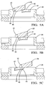
- Fig. 3 illustrates an embodiment of a ramp 28 that includes a locking feature 40 to prevent counter-rotation of the lifting feature 26 after the stops 36 engage the opposite ends of the radial slots 33.
- the locking feature 40 comprises a notch on the upper end of the ramp 28 that engages a trailing edge 44 of the lifting ridge 42.
- the locking feature 40 is configured to allow the trailing edge 44 of the lifting ridge 42 to engage the locking feature 40 prior to the engagement of the stops 36 with the opposite ends of the radial slots 33.
- the lifting ridge 42 When the inner section 30A separates from the outer section 30B following an over-torque condition, the lifting ridge 42 will move along the helical ridge 38 until the trailing edge 44 of the lifting ridge 42 encounters a leading edge 46 of the notch of the locking feature 40. After the trailing edge 44 of the lifting ridge 42 passes the leading edge 46 of the locking feature 40, the lifting ridge 42 will be pulled to a bottom 48 of the notch of the locking feature 40 by armature springs (not shown) that hold the armature 20 away from the rotor 22 when the clutch is disengaged. Thus, the lifting feature 26 is prevented from counter-rotating because the lifting ridge 42 is held in the locking feature 40 by the springs.
- a sequence of the motion of the lifting ridge 42 in relation to the helical ridge 38 resulting in the engagement of the trailing edge 44 with the locking feature 40 is shown in Fig. 5 .
- an automotive air conditioner compressor assembly 10 comprised of a compressor 12, clutch 14 and over-torque protection device 16 is provided.
- the embodiments presented provide improved performance over existing means for disengaging a clutch 14 in response to an over-torque condition.
- the over-torque protection device 16 can quickly decouple the clutch 14 within less than one revolution; at a typical engine idle speed of 600 RPM, less than 100 milliseconds.
- Thermal fuses and thermal sensors may require more time for friction to generate sufficient heat to raise the temperature of the clutch 14 to their activation point.
- Motion sensors may also require more time to detect that the compressor has stopped rotating or that a speed differential exists between the compressor and accessory drive.
- Thermal fuses and thermal sensors are not desirable for over-torque protection devices in automotive air conditioner compressor assemblies 10 where the accessory drive pulley 18 has a low engagement percentage.
- the accessory drive pulley 18 may experience belt slip during an over-torque condition before slip between the armature 20 and rotor 22 occurs, causing failure of the accessory drive belt.
- the automotive air conditioning compressor assembly 10 presented here may be used with an accessory drive pulley 18 having a low engagement percentage because the frangible element 30 may be configured so that the torque required to break the spokes 34 is lower than the belt slip torque.
- the over-torque protection devices 16 presented here axially urges apart the outer section 30B from the inner section 30A so that they are no longer coplanar; preventing the broken ends of the spokes 34 from coming into contact during subsequent rotation.
- the over-rotation feature 32 may be configured so that the rotation of the outer section 30B stops before the broken ends of the spokes on the outer section 30B contact the broken ends of the spokes 34 on the inner section 30A.
- An additional embodiment may include a method and/or apparatus to monitor current in the coil 24 using an electronic controller and de-energize the coil 24 when a current anomaly caused by the armature 20 being separated from the rotor 22 is detected. This would provide additional protection against inadvertent clutch reengagement during an over-torque condition.
Claims (5)
- Dispositif d'embrayage à utiliser avec un compresseur d'air conditionné automobile comprenant :un embrayage (14) opérationnel dans un état engagé dans lequel un entraînement accessoire est couplé à un compresseur (12) en pressant une armature (20) et un rotor (22) l'un contre l'autre pour faire fonctionner le compresseur (12) et opérationnel dans un état désengagé, etun dispositif de protection contre un sur-couple interposé entre le compresseur (12) et l'entraînement accessoire, ledit dispositif de protection contre un sur-couple étant configuré pour découpler le compresseur (12) et l'entraînement accessoire quand une condition de sur-couple se produit, ledit dispositif de protection contre un sur-couple comprenant un élément frangible (30) adapté pour se rompre quand la condition de sur-couple se produit afin de découpler mécaniquement le compresseur (12) et l'entraînement accessoire, caractérisé en ce queune rampe (28) est couplée à l'élément frangible (30) et une fonctionnalité de levage (26) est couplée à l'entraînement accessoire, la rampe (28) définissant une crête hélicoïdale (38), et la fonctionnalité de levage (26) définissant une crête de levage (42) venant en prise avec la crête hélicoïdale (38), dans lequel quand l'élément frangible (30) se rompt, une rotation relative entre la fonctionnalité de levage (26) et la rampe (28) éloigne l'armature (20) et le rotor (22) pour découpler le compresseur (12) et l'entraînement accessoire, etdans lequel une fonctionnalité de sur-rotation (32) est couplée à l'élément infrangible (30) en limitant la rotation relative de la fonctionnalité de levage (26) à moins d'une rotation après la rupture de l'élément frangible (30), etdans lequel une fonctionnalité de verrouillage (40) qui empêche une rotation en sens contraire de la fonctionnalité de levage (26) après qu'une rotation relative entre la fonctionnalité de levage (26) et la rampe (28) a éloigné l'armature (20) et le rotor (22) l'un de l'autre pour découpler le compresseur (12) et l'entraînement accessoire.
- Ensemble d'embrayage selon la revendication 1, dans lequel la fonctionnalité de verrouillage (40) comprend une encoche sur le bord d'attaque de la rampe (28) qui vient en prise avec le bord de fuite de la fonctionnalité de levage (40).
- Ensemble d'embrayages selon une quelconque des revendications 1 ou 2, dans lequel l'élément frangible (30) comprend des rayons (34), dans lequel lesdits rayons (34) sont adaptés pour se rompre quand l'élément frangible (30) est soumis à des charges de couple supérieures à un seuil de couple indicatif de la condition de sur-couple.
- Ensemble d'embrayages selon la revendication 3, dans lequel lesdits rayons (34) sont estampés afin d'être d'une épaisseur contrôlée, de manière à définir plus précisément un couple de réaction.
- Ensemble de compresseur d'air conditionné automobile (10) comprenant :un compresseur (12) opérationnel pour compresser un matériau à l'intérieur du compresseur, ledit compresseur étant capable de présenter une condition de sur-couple etun ensemble d'embrayage selon une quelconque des revendications précédentes.
Applications Claiming Priority (1)
| Application Number | Priority Date | Filing Date | Title |
|---|---|---|---|
| US13/050,159 US8517698B2 (en) | 2011-03-17 | 2011-03-17 | Air conditioning compressor over-torque protector |
Publications (3)
| Publication Number | Publication Date |
|---|---|
| EP2500596A2 EP2500596A2 (fr) | 2012-09-19 |
| EP2500596A3 EP2500596A3 (fr) | 2013-08-14 |
| EP2500596B1 true EP2500596B1 (fr) | 2016-02-03 |
Family
ID=45808213
Family Applications (1)
| Application Number | Title | Priority Date | Filing Date |
|---|---|---|---|
| EP12157706.8A Not-in-force EP2500596B1 (fr) | 2011-03-17 | 2012-03-01 | Protecteur de surcouple pour compresseur de climatisation |
Country Status (3)
| Country | Link |
|---|---|
| US (1) | US8517698B2 (fr) |
| EP (1) | EP2500596B1 (fr) |
| CN (1) | CN102678531B (fr) |
Families Citing this family (10)
| Publication number | Priority date | Publication date | Assignee | Title |
|---|---|---|---|---|
| US20160121899A1 (en) * | 2014-10-29 | 2016-05-05 | GM Global Technology Operations LLC | System with slippable torque-transmission device connecting engine crankshaft and engine-driven component and vehicle |
| CN105782284B (zh) * | 2014-12-23 | 2019-08-23 | 华域三电汽车空调有限公司 | 扭矩限定器 |
| CN105736593B (zh) * | 2016-04-26 | 2018-08-17 | 安徽昊方机电股份有限公司 | 一种抗冲击过扭矩保护汽车空调压缩机驱动器 |
| WO2018099982A1 (fr) | 2016-11-30 | 2018-06-07 | Saint-Gobain Performance Plastics Rencol Limited | Ensemble de couple réglable |
| CN107013609B (zh) * | 2017-04-18 | 2023-09-19 | 安徽昊方机电股份有限公司 | 一种汽车空调定扭矩驱动保护器 |
| JP6680272B2 (ja) | 2017-06-23 | 2020-04-15 | 株式会社デンソー | 動力伝達装置 |
| US11149798B2 (en) * | 2017-07-20 | 2021-10-19 | Litens Automotive Partnership | Rotary clutch assembly with actuator having threadingly engaged two-component armature |
| US11002320B2 (en) | 2019-01-14 | 2021-05-11 | Henry C. Chu | Clutch device for compressor |
| US11660092B2 (en) * | 2020-09-29 | 2023-05-30 | Covidien Lp | Adapter for securing loading units to handle assemblies of surgical stapling instruments |
| EP4074596B1 (fr) * | 2021-04-12 | 2023-05-31 | Ratier-Figeac SAS | Disque de frein avec fusible thermique intégré et procédé de fabrication d'un disque de frein avec fusible thermique intégré |
Family Cites Families (14)
| Publication number | Priority date | Publication date | Assignee | Title |
|---|---|---|---|---|
| US2901076A (en) * | 1955-02-08 | 1959-08-25 | Dean Peter Payne | Overload protection for power drives |
| SE405758B (sv) * | 1975-11-13 | 1978-12-27 | Aberg Martin B | Sekerhetsanordning vid kugghjulsvexel |
| US4977927A (en) * | 1990-01-16 | 1990-12-18 | Hill James H | Free flow fitting |
| JP2575892Y2 (ja) | 1992-09-02 | 1998-07-02 | サンデン株式会社 | プーリー直結型コンプレッサー |
| JPH08319945A (ja) * | 1995-05-25 | 1996-12-03 | Zexel Corp | クラッチレス圧縮機 |
| JPH10306774A (ja) | 1997-03-03 | 1998-11-17 | Luk Fahrzeug Hydraulik Gmbh & Co Kg | 自動車の空気調和装置用圧縮機 |
| US6742350B2 (en) * | 2001-11-03 | 2004-06-01 | Nippon Soken, Inc. | Hybrid compressor device |
| JP4273800B2 (ja) | 2002-04-01 | 2009-06-03 | 株式会社デンソー | トルクリミッターを備えている圧縮機 |
| DE10317116B4 (de) * | 2002-04-16 | 2019-07-25 | Denso Corporation | Kupplungseinrichtung |
| DE602004003068T2 (de) | 2003-07-18 | 2007-03-01 | Calsonic Kansei Corp. | Verbindungselement |
| KR101089560B1 (ko) | 2004-03-18 | 2011-12-05 | 한라공조주식회사 | 클러치리스 압축기의 동력전달장치 |
| JP2006200570A (ja) * | 2005-01-18 | 2006-08-03 | Sanden Corp | 電磁クラッチ |
| US7666100B2 (en) * | 2005-10-04 | 2010-02-23 | Denso Corporation | Power transmission device |
| CN100573072C (zh) * | 2007-05-11 | 2009-12-23 | 洛阳轴研科技股份有限公司 | 汽车空调压缩机电磁离合器动态扭矩自动试验方法及装置 |
-
2011
- 2011-03-17 US US13/050,159 patent/US8517698B2/en active Active
-
2012
- 2012-03-01 EP EP12157706.8A patent/EP2500596B1/fr not_active Not-in-force
- 2012-03-16 CN CN201210082546.7A patent/CN102678531B/zh not_active Expired - Fee Related
Also Published As
| Publication number | Publication date |
|---|---|
| US8517698B2 (en) | 2013-08-27 |
| EP2500596A2 (fr) | 2012-09-19 |
| US20120237361A1 (en) | 2012-09-20 |
| CN102678531B (zh) | 2017-03-01 |
| CN102678531A (zh) | 2012-09-19 |
| EP2500596A3 (fr) | 2013-08-14 |
Similar Documents
| Publication | Publication Date | Title |
|---|---|---|
| EP2500596B1 (fr) | Protecteur de surcouple pour compresseur de climatisation | |
| US5443372A (en) | Coupling mechanism for a compressor | |
| US10113596B2 (en) | Power transmission device | |
| EP1681484B1 (fr) | Embrayage électromagnétique | |
| CN109790908B (zh) | 过载保护装置 | |
| EP3390865B1 (fr) | Pompe à huile hybride | |
| EP3021465B1 (fr) | Unité de connexion actionnée électromécaniquement réinitialisable pour générateurs | |
| JP5263129B2 (ja) | 動力伝達装置 | |
| JP5445178B2 (ja) | 電磁クラッチ | |
| WO2019138718A1 (fr) | Dispositif de transmission d'énergie | |
| EP3494320B1 (fr) | Bague de serrage d'arbre | |
| JP5879972B2 (ja) | 電磁クラッチ用カップリング | |
| JP2000170870A (ja) | 動力伝達機構 | |
| US7040989B2 (en) | Power transmission device | |
| US4176737A (en) | Drive mechanism | |
| EP3440385B1 (fr) | Pompe à huile hybride | |
| US8056689B2 (en) | Water pump disconnect clutch | |
| JP2011158002A (ja) | 電磁クラッチ | |
| US4125180A (en) | Disconnect mechanism for compressor drive | |
| US3241332A (en) | Automatic disconnect device for refrigeration compressors | |
| KR20100065592A (ko) | 전자클러치의 필드코일 어셈블리 | |
| CN109923325B (zh) | 电磁离合器及包括该电磁离合器的压缩机 | |
| WO2014157276A1 (fr) | Dispositif de transmission d'énergie motrice | |
| KR20210015165A (ko) | 클러치 및 이를 포함하는 압축기 | |
| CN117989251A (zh) | 离合器组件和包括离合器组件的旋转系统 |
Legal Events
| Date | Code | Title | Description |
|---|---|---|---|
| PUAI | Public reference made under article 153(3) epc to a published international application that has entered the european phase |
Free format text: ORIGINAL CODE: 0009012 |
|
| AK | Designated contracting states |
Kind code of ref document: A2 Designated state(s): AL AT BE BG CH CY CZ DE DK EE ES FI FR GB GR HR HU IE IS IT LI LT LU LV MC MK MT NL NO PL PT RO RS SE SI SK SM TR |
|
| AX | Request for extension of the european patent |
Extension state: BA ME |
|
| PUAL | Search report despatched |
Free format text: ORIGINAL CODE: 0009013 |
|
| AK | Designated contracting states |
Kind code of ref document: A3 Designated state(s): AL AT BE BG CH CY CZ DE DK EE ES FI FR GB GR HR HU IE IS IT LI LT LU LV MC MK MT NL NO PL PT RO RS SE SI SK SM TR |
|
| AX | Request for extension of the european patent |
Extension state: BA ME |
|
| RIC1 | Information provided on ipc code assigned before grant |
Ipc: F16D 27/112 20060101AFI20130711BHEP Ipc: F16D 9/00 20060101ALI20130711BHEP Ipc: F16D 9/06 20060101ALI20130711BHEP |
|
| 17P | Request for examination filed |
Effective date: 20140214 |
|
| RBV | Designated contracting states (corrected) |
Designated state(s): AL AT BE BG CH CY CZ DE DK EE ES FI FR GB GR HR HU IE IS IT LI LT LU LV MC MK MT NL NO PL PT RO RS SE SI SK SM TR |
|
| 17Q | First examination report despatched |
Effective date: 20140618 |
|
| GRAP | Despatch of communication of intention to grant a patent |
Free format text: ORIGINAL CODE: EPIDOSNIGR1 |
|
| INTG | Intention to grant announced |
Effective date: 20150420 |
|
| RAP1 | Party data changed (applicant data changed or rights of an application transferred) |
Owner name: MAHLE INTERNATIONAL GMBH |
|
| GRAS | Grant fee paid |
Free format text: ORIGINAL CODE: EPIDOSNIGR3 |
|
| GRAA | (expected) grant |
Free format text: ORIGINAL CODE: 0009210 |
|
| AK | Designated contracting states |
Kind code of ref document: B1 Designated state(s): AL AT BE BG CH CY CZ DE DK EE ES FI FR GB GR HR HU IE IS IT LI LT LU LV MC MK MT NL NO PL PT RO RS SE SI SK SM TR |
|
| REG | Reference to a national code |
Ref country code: GB Ref legal event code: FG4D |
|
| REG | Reference to a national code |
Ref country code: AT Ref legal event code: REF Ref document number: 773843 Country of ref document: AT Kind code of ref document: T Effective date: 20160215 Ref country code: CH Ref legal event code: EP |
|
| REG | Reference to a national code |
Ref country code: IE Ref legal event code: FG4D |
|
| REG | Reference to a national code |
Ref country code: DE Ref legal event code: R096 Ref document number: 602012014278 Country of ref document: DE |
|
| REG | Reference to a national code |
Ref country code: FR Ref legal event code: PLFP Year of fee payment: 5 |
|
| REG | Reference to a national code |
Ref country code: LT Ref legal event code: MG4D Ref country code: NL Ref legal event code: MP Effective date: 20160203 |
|
| REG | Reference to a national code |
Ref country code: AT Ref legal event code: MK05 Ref document number: 773843 Country of ref document: AT Kind code of ref document: T Effective date: 20160203 |
|
| PG25 | Lapsed in a contracting state [announced via postgrant information from national office to epo] |
Ref country code: FI Free format text: LAPSE BECAUSE OF FAILURE TO SUBMIT A TRANSLATION OF THE DESCRIPTION OR TO PAY THE FEE WITHIN THE PRESCRIBED TIME-LIMIT Effective date: 20160203 Ref country code: NO Free format text: LAPSE BECAUSE OF FAILURE TO SUBMIT A TRANSLATION OF THE DESCRIPTION OR TO PAY THE FEE WITHIN THE PRESCRIBED TIME-LIMIT Effective date: 20160503 Ref country code: HR Free format text: LAPSE BECAUSE OF FAILURE TO SUBMIT A TRANSLATION OF THE DESCRIPTION OR TO PAY THE FEE WITHIN THE PRESCRIBED TIME-LIMIT Effective date: 20160203 Ref country code: GR Free format text: LAPSE BECAUSE OF FAILURE TO SUBMIT A TRANSLATION OF THE DESCRIPTION OR TO PAY THE FEE WITHIN THE PRESCRIBED TIME-LIMIT Effective date: 20160504 Ref country code: IT Free format text: LAPSE BECAUSE OF FAILURE TO SUBMIT A TRANSLATION OF THE DESCRIPTION OR TO PAY THE FEE WITHIN THE PRESCRIBED TIME-LIMIT Effective date: 20160203 Ref country code: ES Free format text: LAPSE BECAUSE OF FAILURE TO SUBMIT A TRANSLATION OF THE DESCRIPTION OR TO PAY THE FEE WITHIN THE PRESCRIBED TIME-LIMIT Effective date: 20160203 |
|
| PG25 | Lapsed in a contracting state [announced via postgrant information from national office to epo] |
Ref country code: LV Free format text: LAPSE BECAUSE OF FAILURE TO SUBMIT A TRANSLATION OF THE DESCRIPTION OR TO PAY THE FEE WITHIN THE PRESCRIBED TIME-LIMIT Effective date: 20160203 Ref country code: LT Free format text: LAPSE BECAUSE OF FAILURE TO SUBMIT A TRANSLATION OF THE DESCRIPTION OR TO PAY THE FEE WITHIN THE PRESCRIBED TIME-LIMIT Effective date: 20160203 Ref country code: NL Free format text: LAPSE BECAUSE OF FAILURE TO SUBMIT A TRANSLATION OF THE DESCRIPTION OR TO PAY THE FEE WITHIN THE PRESCRIBED TIME-LIMIT Effective date: 20160203 Ref country code: BE Free format text: LAPSE BECAUSE OF NON-PAYMENT OF DUE FEES Effective date: 20160331 Ref country code: PL Free format text: LAPSE BECAUSE OF FAILURE TO SUBMIT A TRANSLATION OF THE DESCRIPTION OR TO PAY THE FEE WITHIN THE PRESCRIBED TIME-LIMIT Effective date: 20160203 Ref country code: IS Free format text: LAPSE BECAUSE OF FAILURE TO SUBMIT A TRANSLATION OF THE DESCRIPTION OR TO PAY THE FEE WITHIN THE PRESCRIBED TIME-LIMIT Effective date: 20160603 Ref country code: RS Free format text: LAPSE BECAUSE OF FAILURE TO SUBMIT A TRANSLATION OF THE DESCRIPTION OR TO PAY THE FEE WITHIN THE PRESCRIBED TIME-LIMIT Effective date: 20160203 Ref country code: SE Free format text: LAPSE BECAUSE OF FAILURE TO SUBMIT A TRANSLATION OF THE DESCRIPTION OR TO PAY THE FEE WITHIN THE PRESCRIBED TIME-LIMIT Effective date: 20160203 Ref country code: PT Free format text: LAPSE BECAUSE OF FAILURE TO SUBMIT A TRANSLATION OF THE DESCRIPTION OR TO PAY THE FEE WITHIN THE PRESCRIBED TIME-LIMIT Effective date: 20160603 Ref country code: AT Free format text: LAPSE BECAUSE OF FAILURE TO SUBMIT A TRANSLATION OF THE DESCRIPTION OR TO PAY THE FEE WITHIN THE PRESCRIBED TIME-LIMIT Effective date: 20160203 |
|
| PG25 | Lapsed in a contracting state [announced via postgrant information from national office to epo] |
Ref country code: EE Free format text: LAPSE BECAUSE OF FAILURE TO SUBMIT A TRANSLATION OF THE DESCRIPTION OR TO PAY THE FEE WITHIN THE PRESCRIBED TIME-LIMIT Effective date: 20160203 Ref country code: DK Free format text: LAPSE BECAUSE OF FAILURE TO SUBMIT A TRANSLATION OF THE DESCRIPTION OR TO PAY THE FEE WITHIN THE PRESCRIBED TIME-LIMIT Effective date: 20160203 |
|
| REG | Reference to a national code |
Ref country code: CH Ref legal event code: PL |
|
| REG | Reference to a national code |
Ref country code: DE Ref legal event code: R097 Ref document number: 602012014278 Country of ref document: DE |
|
| PG25 | Lapsed in a contracting state [announced via postgrant information from national office to epo] |
Ref country code: RO Free format text: LAPSE BECAUSE OF FAILURE TO SUBMIT A TRANSLATION OF THE DESCRIPTION OR TO PAY THE FEE WITHIN THE PRESCRIBED TIME-LIMIT Effective date: 20160203 Ref country code: CZ Free format text: LAPSE BECAUSE OF FAILURE TO SUBMIT A TRANSLATION OF THE DESCRIPTION OR TO PAY THE FEE WITHIN THE PRESCRIBED TIME-LIMIT Effective date: 20160203 Ref country code: SM Free format text: LAPSE BECAUSE OF FAILURE TO SUBMIT A TRANSLATION OF THE DESCRIPTION OR TO PAY THE FEE WITHIN THE PRESCRIBED TIME-LIMIT Effective date: 20160203 Ref country code: SK Free format text: LAPSE BECAUSE OF FAILURE TO SUBMIT A TRANSLATION OF THE DESCRIPTION OR TO PAY THE FEE WITHIN THE PRESCRIBED TIME-LIMIT Effective date: 20160203 |
|
| PLBE | No opposition filed within time limit |
Free format text: ORIGINAL CODE: 0009261 |
|
| STAA | Information on the status of an ep patent application or granted ep patent |
Free format text: STATUS: NO OPPOSITION FILED WITHIN TIME LIMIT |
|
| REG | Reference to a national code |
Ref country code: IE Ref legal event code: MM4A |
|
| PG25 | Lapsed in a contracting state [announced via postgrant information from national office to epo] |
Ref country code: BE Free format text: LAPSE BECAUSE OF FAILURE TO SUBMIT A TRANSLATION OF THE DESCRIPTION OR TO PAY THE FEE WITHIN THE PRESCRIBED TIME-LIMIT Effective date: 20160203 |
|
| 26N | No opposition filed |
Effective date: 20161104 |
|
| GBPC | Gb: european patent ceased through non-payment of renewal fee |
Effective date: 20160503 |
|
| PG25 | Lapsed in a contracting state [announced via postgrant information from national office to epo] |
Ref country code: CH Free format text: LAPSE BECAUSE OF NON-PAYMENT OF DUE FEES Effective date: 20160331 Ref country code: IE Free format text: LAPSE BECAUSE OF NON-PAYMENT OF DUE FEES Effective date: 20160301 Ref country code: LI Free format text: LAPSE BECAUSE OF NON-PAYMENT OF DUE FEES Effective date: 20160331 |
|
| PG25 | Lapsed in a contracting state [announced via postgrant information from national office to epo] |
Ref country code: SI Free format text: LAPSE BECAUSE OF FAILURE TO SUBMIT A TRANSLATION OF THE DESCRIPTION OR TO PAY THE FEE WITHIN THE PRESCRIBED TIME-LIMIT Effective date: 20160203 Ref country code: BG Free format text: LAPSE BECAUSE OF FAILURE TO SUBMIT A TRANSLATION OF THE DESCRIPTION OR TO PAY THE FEE WITHIN THE PRESCRIBED TIME-LIMIT Effective date: 20160503 |
|
| REG | Reference to a national code |
Ref country code: FR Ref legal event code: PLFP Year of fee payment: 6 |
|
| PG25 | Lapsed in a contracting state [announced via postgrant information from national office to epo] |
Ref country code: GB Free format text: LAPSE BECAUSE OF NON-PAYMENT OF DUE FEES Effective date: 20160503 |
|
| PG25 | Lapsed in a contracting state [announced via postgrant information from national office to epo] |
Ref country code: MT Free format text: LAPSE BECAUSE OF FAILURE TO SUBMIT A TRANSLATION OF THE DESCRIPTION OR TO PAY THE FEE WITHIN THE PRESCRIBED TIME-LIMIT Effective date: 20160203 |
|
| REG | Reference to a national code |
Ref country code: FR Ref legal event code: PLFP Year of fee payment: 7 |
|
| PG25 | Lapsed in a contracting state [announced via postgrant information from national office to epo] |
Ref country code: HU Free format text: LAPSE BECAUSE OF FAILURE TO SUBMIT A TRANSLATION OF THE DESCRIPTION OR TO PAY THE FEE WITHIN THE PRESCRIBED TIME-LIMIT; INVALID AB INITIO Effective date: 20120301 Ref country code: CY Free format text: LAPSE BECAUSE OF FAILURE TO SUBMIT A TRANSLATION OF THE DESCRIPTION OR TO PAY THE FEE WITHIN THE PRESCRIBED TIME-LIMIT Effective date: 20160203 |
|
| PG25 | Lapsed in a contracting state [announced via postgrant information from national office to epo] |
Ref country code: MT Free format text: LAPSE BECAUSE OF FAILURE TO SUBMIT A TRANSLATION OF THE DESCRIPTION OR TO PAY THE FEE WITHIN THE PRESCRIBED TIME-LIMIT Effective date: 20160331 Ref country code: TR Free format text: LAPSE BECAUSE OF FAILURE TO SUBMIT A TRANSLATION OF THE DESCRIPTION OR TO PAY THE FEE WITHIN THE PRESCRIBED TIME-LIMIT Effective date: 20160203 Ref country code: MK Free format text: LAPSE BECAUSE OF FAILURE TO SUBMIT A TRANSLATION OF THE DESCRIPTION OR TO PAY THE FEE WITHIN THE PRESCRIBED TIME-LIMIT Effective date: 20160203 Ref country code: MC Free format text: LAPSE BECAUSE OF FAILURE TO SUBMIT A TRANSLATION OF THE DESCRIPTION OR TO PAY THE FEE WITHIN THE PRESCRIBED TIME-LIMIT Effective date: 20160203 Ref country code: LU Free format text: LAPSE BECAUSE OF NON-PAYMENT OF DUE FEES Effective date: 20160301 |
|
| PG25 | Lapsed in a contracting state [announced via postgrant information from national office to epo] |
Ref country code: AL Free format text: LAPSE BECAUSE OF FAILURE TO SUBMIT A TRANSLATION OF THE DESCRIPTION OR TO PAY THE FEE WITHIN THE PRESCRIBED TIME-LIMIT Effective date: 20160203 |
|
| PGFP | Annual fee paid to national office [announced via postgrant information from national office to epo] |
Ref country code: FR Payment date: 20200326 Year of fee payment: 9 |
|
| PGFP | Annual fee paid to national office [announced via postgrant information from national office to epo] |
Ref country code: DE Payment date: 20200528 Year of fee payment: 9 |
|
| REG | Reference to a national code |
Ref country code: DE Ref legal event code: R119 Ref document number: 602012014278 Country of ref document: DE |
|
| PG25 | Lapsed in a contracting state [announced via postgrant information from national office to epo] |
Ref country code: DE Free format text: LAPSE BECAUSE OF NON-PAYMENT OF DUE FEES Effective date: 20211001 Ref country code: FR Free format text: LAPSE BECAUSE OF NON-PAYMENT OF DUE FEES Effective date: 20210331 |